nhd-0216k3z-fs(rgb)-fbw-v3 · nhd-0216k3z-fs(rgb) ... f- transflective . s(rgb)- side led...
TRANSCRIPT

NHD-0216K3Z-FS(RGB)-FBW-V3 Serial Liquid Crystal Display Module
NHD- Newhaven Display 0216- 2 Lines x 16 Characters K3Z- Model F- Transflective S(RGB)- Side LED Backlights (Red-Green-Blue) F- FSTN Positive B- 6:00 Optimal View W- Wide Temperature V3- Firmware Version 3.00 RoHS Compliant
Newhaven Display International, Inc.
2661 Galvin Ct. Elgin IL, 60124
Ph: 847-844-8795 Fax: 847-844-8796
www.newhavendisplay.com [email protected] [email protected]

[2]
Document Revision History Revision Date Description Changed by
0 5/16/2012 Initial Release SB 1 10/1/2012 Character address code updated AK 2 5/30/2013 Electrical characteristics updated, RGB backlight note added
in command table AK
3 1/28/16 Module Redesign SB 4 12/29/16 Backlight & PCB Redesign SB
Functions and Features
• 2 lines x 16 characters • Red/Green/Blue LED backlights • Serial Interface: I2C, SPI or RS-232(TTL) • +5.0V power supply • 1/16 duty, 1/5 bias • 5x8 pixels with cursor • RoHS Compliant

PROPRI
ETARY
1 2 3 4 5 6
A
B
C
D
B
C
D
1 2 3 4 5 6
Mechanical Drawing
A
[3]The information contained herein is the exclusive property of Newhaven Display International, Inc. and shall not be copied, reproduced, and/or disclosed in any format without permission.
NHD-0216K3Z-FS(RGB)-FBW-V312/29/16Date
Unit
Part Number:
mmGen. Tol.
±0.3
Rev Description Date
Notes:1. Driver: 1/16 Duty, 1/5 Bias2. Voltage: 5.0V VDD3. Display Mode: FSTN Positive / Transflective4. Optimal View: 6:005. Backlight: Red, Blue & Green LED Backlight6. Driver IC: PIC16F690 & ST7066U7. Interface: RS232 (TTL) / SPI / I2C

[4]
Pin Description J1: Pin No. Symbol External Connection Function Description
1 RX MPU RS-232 (TTL) Serial input port 2 VSS Power Supply Ground 3 VDD Power Supply Supply Voltage for Logic (+5.0V)
J2: Pin No. Symbol External Connection Function Description
1 SPISS MPU SPI Slave Select (NC in I2C mode) 2 SDO NC No Connect 3 SCK/SCL MPU Serial Clock 4 SDI/SDA MPU Serial Data In (SPI) / Serial Data (I2C) 5 VSS Power Supply Ground 6 VDD Power Supply Supply Voltage for Logic (+5.0V)
J3: Pin No. Symbol External Connection Function Description
1 K Power Supply Backlight Common Cathode (Ground) 2 A-RED Power Supply Red LED Anode (2.0V) 3 A-GREEN Power Supply Green LED Anode (3.0V) 4 A-BLUE Power Supply Blue LED Anode (3.0V)
Recommended LCD connector: 2.54mm pitch pins on P1 or P2 Backlight connector: controlled by command Mates with: -
Jumper Communication Selection R1 R2 Protocol Description
Short Short TEST Self-test Open Short SPI 100KHz max clock Short Open I2C 100KHz max clock Open Open RS-232 5V, TTL signal

[5]
Electrical Characteristics Item Symbol Condition Min. Typ. Max. Unit
Operating Temperature Range TOP - -20 - +70 ⁰C Storage Temperature Range TST - -30 - +80 ⁰C Supply Voltage VDD - 4.5 5.0 5.5 V Supply Current (LCD) IDD VDD = 5.0V
TOP = 25°C 2 4 8 mA
Supply for LCD (contrast) VDD-V0 4.2 4.5 4.8 V “H” Level input VIG - 0.8 * VDD - VDD V “L” Level input VIL - VSS - 0.2 * VDD V Backlight Supply Current – Red ILED - - 10 15 mA Backlight Supply Voltage – Red VLED ILED = 10 mA 1.8 2.0 2.2 V Backlight Supply Current – Green ILED - - 15 20 mA Backlight Supply Voltage – Green VLED ILED = 15 mA 2.8 3.0 3.2 V Backlight Supply Current – Blue ILED - - 15 20 mA Backlight Supply Voltage – Blue VLED ILED = 15 mA 2.8 3.0 3.2 V *The LED of the backlight is driven by current; drive voltage is for reference only. Drive voltage must be selected to ensure backlight current drain is below MAX level stated.
Optical Characteristics Item Symbol Condition Min. Typ. Max. Unit
Optimal Viewing Angles
Top ϕY+
CR ≥ 3
- 15 - ⁰ Bottom ϕY- - 45 - ⁰ Left θX- - 45 - ⁰ Right θX+ - 45 - ⁰
Contrast Ratio CR - 3 5 - -
Response Time Rise TR
TOP = 25°C - 150 400 ms
Fall TF - 150 400 ms
Controller Information Built-in PIC16F690 controller. Please download specification at http://www.newhavendisplay.com/app_notes/PIC16F690.pdf

[6]
Communication Information This display uses a built-in PIC16F690 for serial communication. 100mS delay is required upon power-up for the built-in PIC to initialize the display controller.
I2C protocol: To enter the I2C mode, place a jumper on R1. SDA and SDK have pull-up resistors (10K Ohm) on R7 and R8. The default I2C address is 80 (50 hex). The I2C address can be changed to any 8-bit value by command function, with the exception that the LSB (least significant bit) must always be ‘0’. Once the I2C address has been changed, it will be saved in the system memory, and it will revert back to the default address if either RS-232 or SPI protocol is selected. The I2C interface is capable of receiving data at up to 100KHz clock rate. SPI protocol: To enter the SPI mode, place a jumper on R2. SPI mode has a normally high level idle clock. When Slave Select is LOW, data is sampled on the rising edge of the Clock. The SPI interface is capable of receiving data at up to 100KHz clock rate. RS-232 (TTL) protocol: To enter the RS-232 mode, both R1 and R2 should be open. The RS-232 signal must be 5V TTL compatible. Communication format is 8-bit data, 1 Stop bit, no parity, no hand-shaking. Default BAUD rate is 9600, and is changeable with a command function. Once the BAUD rate has been changed, it will be saved in the system memory, and it will revert back to the default address if either I2C or SPI protocol is selected.
ASCII Text To display normal text, just enter its ASCII number. A number from 0x00 to 0x07 displays the user defined custom character, 0x20 to 0x7F displays the standard set of characters, 0xA0 to 0xFD display characters and symbols that are factory-masked on the ST7066U controller. 0xFE is reserved.
[7]
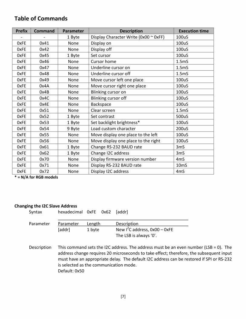
Table of Commands Prefix Command Parameter Description Execution time
- - 1 Byte Display Character Write (0x00 ~ 0xFF) 100uS 0xFE 0x41 None Display on 100uS 0xFE 0x42 None Display off 100uS 0xFE 0x45 1 Byte Set cursor 100uS 0xFE 0x46 None Cursor home 1.5mS 0xFE 0x47 None Underline cursor on 1.5mS 0xFE 0x48 None Underline cursor off 1.5mS 0xFE 0x49 None Move cursor left one place 100uS 0xFE 0x4A None Move cursor right one place 100uS 0xFE 0x4B None Blinking cursor on 100uS 0xFE 0x4C None Blinking cursor off 100uS 0xFE 0x4E None Backspace 100uS 0xFE 0x51 None Clear screen 1.5mS 0xFE 0x52 1 Byte Set contrast 500uS 0xFE 0x53 1 Byte Set backlight brightness* 100uS 0xFE 0x54 9 Byte Load custom character 200uS 0xFE 0x55 None Move display one place to the left 100uS 0xFE 0x56 None Move display one place to the right 100uS 0xFE 0x61 1 Byte Change RS-232 BAUD rate 3mS 0xFE 0x62 1 Byte Change I2C address 3mS 0xFE 0x70 None Display firmware version number 4mS 0xFE 0x71 None Display RS-232 BAUD rate 10mS 0xFE 0x72 None Display I2C address 4mS
* = N/A for RGB models Changing the I2C Slave Address
Syntax hexadecimal 0xFE 0x62 [addr] Parameter Parameter Length Description [addr] 1 byte New I2C address, 0x00 – 0xFE The LSB is always ‘0’. Description This command sets the I2C address. The address must be an even number (LSB = 0). The
address change requires 20 microseconds to take effect; therefore, the subsequent input must have an appropriate delay. The default I2C address can be restored if SPI or RS-232 is selected as the communication mode. Default: 0x50

[8]
Changing BAUD Rate Syntax hexadecimal 0xFE 0x61 [baud] Parameter Parameter Length Description [BAUD] 1 byte New RS-232 BAUD Rate, 1 - 8 Description This command sets the RS-232 BAUD rate. The single byte parameter selects the desired
BAUD rate as in the table below. The new BAUD rate requires 20 microseconds to take effect; therefore, the subsequent input must have an appropriate delay. The default BAUD rate can be restored if I2C or SPI is selected as the communication mode. Illegal parameter input will be discarded.
Parameter BAUD 1 300 2 1200 3 2400 4 9600 5 14400 6 19.2K 7 57.6K 8 115.2K
Default: 9600 BAUD
Turn On Display
Syntax hexadecimal 0xFE 0x41 Parameter Parameter Length Description None None Turn on LCD screen Description This command turns on the LCD display screen. The display text is not altered.
Default: LCD screen is on Turn Off Display
Syntax hexadecimal 0xFE 0x42 Parameter Parameter Length Description None None Turn off LCD screen Description This command turns off the LCD display screen. The display text is not altered.
Default: LCD screen is on

[9]
Set Cursor Position Syntax hexadecimal 0xFE 0x45 [pos] Parameter Parameter Length Description
[pos] 1 byte Put cursor at location specified by [pos], 0x00 to 0x67 Description This command moves the cursor to a specified location where the next character will be
displayed. The typical cursor position for a 2-line 16-character display is show below; a cursor position outside these ranges will not be viewable.
Column 1 Column 16
Line 1 0x00 0x0F Line 2 0x40 0x4F
Default: After a reset, the cursor is on position 0x00
Home Cursor
Syntax hexadecimal 0xFE 0x46 Parameter Parameter Length Description None None Position cursor at line 1 column 1 Description This command moves the cursor to line 1, column 1 of the LCD screen. The display text is
not altered. Default: None
Turn On Underline Cursor
Syntax hexadecimal 0xFE 0x47 Parameter Parameter Length Description None None Turn on underline cursor Description This command turns on the underline cursor.
Default: Underline cursor is off Turn Off Underline Cursor
Syntax hexadecimal 0xFE 0x48 Parameter Parameter Length Description None None Turn off underline cursor
Description This command turns off the underline cursor.
Default: Underline cursor is off
[10]
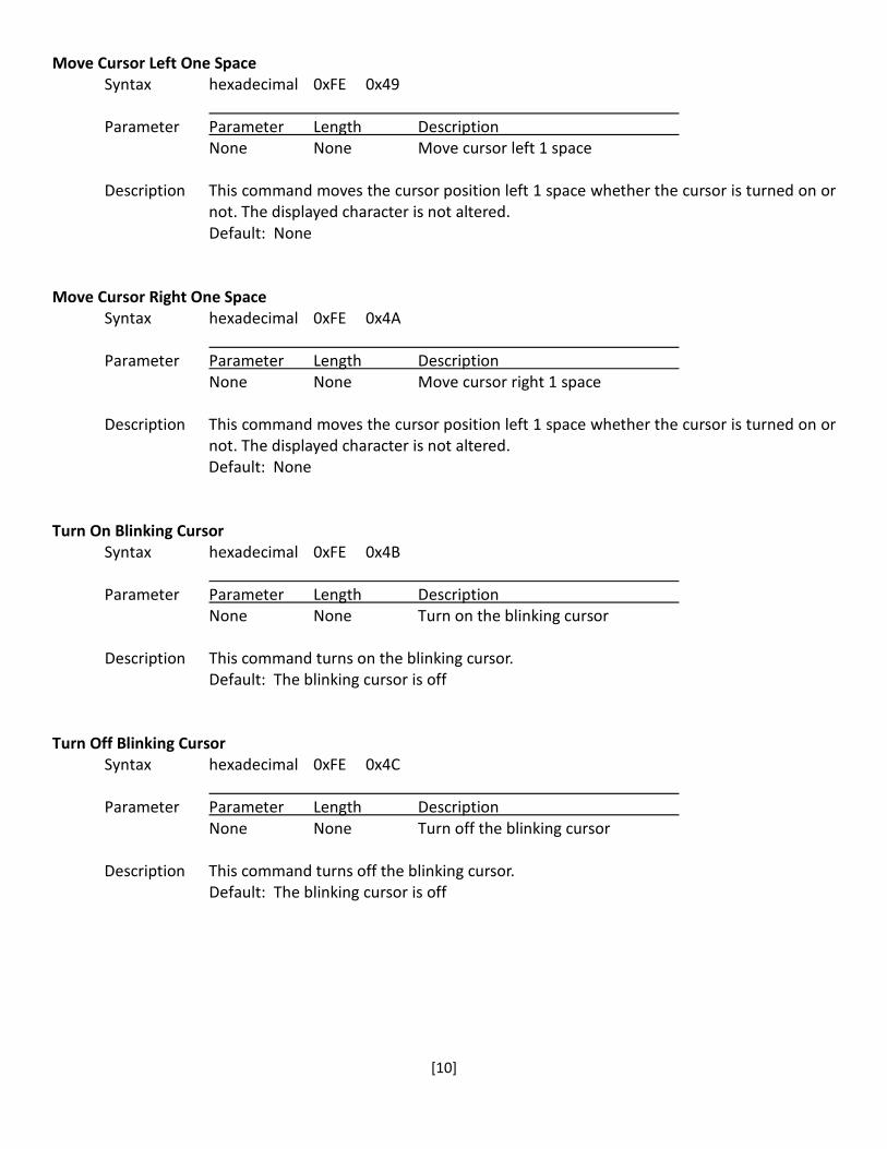
Move Cursor Left One Space Syntax hexadecimal 0xFE 0x49 Parameter Parameter Length Description None None Move cursor left 1 space Description This command moves the cursor position left 1 space whether the cursor is turned on or
not. The displayed character is not altered. Default: None
Move Cursor Right One Space
Syntax hexadecimal 0xFE 0x4A Parameter Parameter Length Description None None Move cursor right 1 space Description This command moves the cursor position left 1 space whether the cursor is turned on or
not. The displayed character is not altered. Default: None
Turn On Blinking Cursor
Syntax hexadecimal 0xFE 0x4B Parameter Parameter Length Description None None Turn on the blinking cursor Description This command turns on the blinking cursor.
Default: The blinking cursor is off Turn Off Blinking Cursor
Syntax hexadecimal 0xFE 0x4C Parameter Parameter Length Description None None Turn off the blinking cursor Description This command turns off the blinking cursor.
Default: The blinking cursor is off

[11]
Back Space Syntax hexadecimal 0xFE 0x4E Parameter Parameter Length Description
None None Move cursor back one space, delete last character.
Description This command is destructive backspace. The cursor is moved back one space and the character on the cursor is deleted. Default: None
Clear Screen
Syntax hexadecimal 0xFE 0x51 Parameter Parameter Length Description
None None Clear LCD and move cursor to line 1 column 1.
Description This command clears the entire display and place the cursor at line 1 column 1. Default: None
Set Display Contrast
Syntax hexadecimal 0xFE 0x52 [contrast] Parameter Parameter Length Description
[contrast] 1 byte Set the display contrast, value between 1 and 50
Description This command sets the display contrast. The contrast setting can be between 1 and 50, where 50 is the highest contrast. Default: 40
Set Backlight Brightness
Syntax hexadecimal 0xFE 0x53 [brightness] Parameter Parameter Length Description
[brightness] 1 byte Set the backlight brightness level, value between 1 and 8 Description This command sets the backlight brightness level. The value can be between 1 and 8.
Default: 8

[12]
Load Custom Characters Syntax hexadecimal 0xFE 0x54 [addr] [d0 …d7] Parameter Parameter Length Description
[addr] 1 byte Custom character address, 0 – 7 [D0...D7] 8 bytes Custom character pattern bit map
Description There is space for eight user-defined custom characters. This command loads the custom
character into one of the eight locations. The custom character pattern is bit mapped into 8 data bytes. The bit map for Spanish character ‘¿’ is shown in table below. To display the custom character, user has to enter the address of the character (0 to 8).
Bit 7 6 5 4 3 2 1 0 Hex
Byte 1 0 0 0 0 0 1 0 0 0x04 Byte 2 0 0 0 0 0 0 0 0 0x00 Byte 3 0 0 0 0 0 1 0 0 0x04 Byte 4 0 0 0 0 1 0 0 0 0x08 Byte 5 0 0 0 1 0 0 0 0 0x10 Byte 6 0 0 0 1 0 0 0 1 0x11 Byte 7 0 0 0 0 1 1 1 0 0x0E Byte 8 0 0 0 0 0 0 0 0 0x00
Default: None
Shift Display to the Left
Syntax hexadecimal 0xFE 0x55 Parameter Parameter Length Description
None None Shift the LCD screen to the left 1 space.
Description This command shifts the display to the left 1 space. The cursor position also moves with the display, and the display data is not altered. Default: None
Shift Display to the Right
Syntax hexadecimal 0xFE 0x56 Parameter Parameter Length Description
None None Shift the LCD screen to the right 1 space. Description This command shifts the display to the right 1 space. The cursor position also moves
with the display, and the display data is not altered. Default: None

[13]
Display Firmware Version Number Syntax hexadecimal 0xFE 0x70 Parameter Parameter Length Description
None None Display the firmware version number. Description This command displays the firmware version.
Default: None Display RS-232 Baud Rate
Syntax hexadecimal 0xFE 0x71 Parameter Parameter Length Description
None None Display Baud Rate Description This command displays the RS-232 BAUD rate.
Default: None Display I2C Address
Syntax hexadecimal 0xFE 0x72 Parameter Parameter Length Description
None None Display I2C Address Description This command displays the current I2C slave address.
Default: None
Example Initialization Program See program code at http://www.newhavendisplay.com/app_notes/Serial_LCD.txt

[14]
Built-in Font Table

[15]
Quality Information Test Item Content of Test Test Condition Note
High Temperature storage Endurance test applying the high storage temperature for a long time.
+80⁰C , 96hrs 2
Low Temperature storage Endurance test applying the low storage temperature for a long time.
-30⁰C , 96hrs 1,2
High Temperature Operation
Endurance test applying the electric stress (voltage & current) and the high thermal stress for a long time.
+70⁰C 96hrs 2
Low Temperature Operation
Endurance test applying the electric stress (voltage & current) and the low thermal stress for a long time.
-20⁰C , 96hrs 1,2
High Temperature / Humidity Operation
Endurance test applying the electric stress (voltage & current) and the high thermal with high humidity stress for a long time.
+40⁰C , 90% RH , 96hrs 1,2
Thermal Shock resistance Endurance test applying the electric stress (voltage & current) during a cycle of low and high thermal stress.
-20⁰C,60min -> +25⁰C,5min -> +70⁰C,60min = 1 cycle 16 cycles
Vibration test Endurance test applying vibration to simulate transportation and use.
10-100Hz , 2g Acceleration. 2 Hrs in each of 3 directions X,Y,Z
3
Static electricity test Endurance test applying electric static discharge.
VS=800V, RS=1.5kΩ, CS=100pF One time
Note 1: No condensation to be observed. Note 2: Conducted after 4 hours of storage at 25⁰C, 0%RH. Note 3: Test performed on product itself, not inside a container.
Precautions for using LCDs/LCMs See Precautions at www.newhavendisplay.com/specs/precautions.pdf
Warranty Information and Terms & Conditions http://www.newhavendisplay.com/index.php?main_page=terms