next generation multi-fiber ferrule using 165 micron pitch
TRANSCRIPT

H. Asada, D. Childers, M. Hughes, T. Ishikawa, S. Lutz, D. Schoellner, K. Shindo, Y. Wada
“Next Generation Multi-Fiber Ferrule Using 165 Micron Pitch Optical Fiber”,
Photonics West Optical Interconnects XXI, SPIE, (2021). http://dx.doi.org/10.1117/12.2578649
Next Generation Multi-Fiber Ferrule Using 165 Micron Pitch Optical
Fiber Hirotaka Asadaa, Darrell Childersb, Mike Hughes*b, Takaaki Ishikawaa, Sharon Lutzb, Dirk
Schoellnerb, Kansei Shindoa, Yasuyuki Wadaa aFujikura Ltd, 1-5-1, Kiba, Koto-ku, Tokyo 135-8512, Japan; bUS Conec Ltd, 1138 25th Street SE;
Hickory, NC 28601.
ABSTRACT
The continued acceleration of switching capacity and link transmission bandwidth is driving the need for new connectors
in next generation optical networks. With 25.6Tb switch ASICs available in 2020 [1], only two years after the
introduction of 12.8Tb switching, the industry is now looking to radical new architectures to achieve 51.2Tb switching,
including the advent of optics integrated or co-packaged with ASIC technology. The standard 250µm pitch used in
multi-fiber ferrules with 125µm cladding diameter optical fiber is physically too large to support the quantity of optical
lanes that will be coupled inside the coming switching platforms.
This paper describes a next generation MT-style ferrule designed for fibers with 80µm cladding diameter on a pitch of
165µm. By decreasing the pitch from 250µm to 165µm, up to 24 fibers can be placed in a single row between the pins
of the MT-16 alignment structure. This tighter pitch enables higher fiber densities coupled directly to or in the proximity
optical Tx/Rx photonic tiles.
Endface geometry models combined with connector mating normal forces are based on the traditional 250µm pitch of
MT-style ferrules. Fiber tip radii, fiber tip coplanarity, ferrule surface endface angles relative to alignment pin bores
were measured empirically and documented on the new design. Varied topologies were combined with different mating
forces demonstrating effective physical contact for the new ferrule. Mated pairs were monitored for attenuation changes
during exposure to industry standard uncontrolled environment temperature cycling. Subsequent specifications for
future end face geometry and mating spring force requirements are proposed.
Keywords: MT Ferrule, 80 micron, 165 micron, MT-16, MT-24
1.1 Applications
1. INTRODUCTION
Next generation networking demands are bringing into question the tradeoffs between higher speed pluggable optics
beyond 400G, bolstered by industry supply chain inertia, and radical changes in photonic solutions such as co-packaged
optics. The ability to indefinitely continue scaling power consumption in the traditional manner by coupling higher
speed optics with ASIC generation is uncertain. Emerging high bandwidth switching technology ASICs integrated with
optical I/O can result in more power efficient, high radix switching solutions, and ultimately flatter architectures.
When considering switch generation with optical I/O tile bandwidths, the density of current optical connector solutions
on 250 micron pitch fiber arrays may not be sufficient. With 100G per optical fiber for 500m reaches at 51.2Tb
switching with a switch radix of 512, 1024 fibers could be serviced by 16 optical tiles at 3.2Tb per tile or 8 optical tiles
at 6.4Tb per tile (Figure 1).
In general, the size of the organic substrate in the package for 1st generation co-packaged designs is anticipated to be
100-150mm [2]. Given the package size, 6.4Tb per tile and 8 tiles per device, the tile size would be approximately 30x
35mm [2]. For such a 16x 400G DR4 applications, the 128 Tx/Rx fibers alone will consume the entire tile edge with a
traditional 250um fiber pitch without any consideration for external laser sourcing. When considering the quantity of
fibers to be managed within the overall package constraints and available real estate within each optical tile, it becomes
evident that moving to fiber arrays with tighter pitches than the traditional 250 microns will be advantageous or even a
requirement in future, high density switching architectures.

H. Asada, D. Childers, M. Hughes, T. Ishikawa, S. Lutz, D. Schoellner, K. Shindo, Y. Wada “Next Generation Multi-Fiber Ferrule Using 165 Micron Pitch Optical Fiber”,
Photonics West Optical Interconnects XXI, SPIE, (2021). http://dx.doi.org/10.1117/12.2578649
Figure 1. Fibers per optical tile at 51.2Tb switching with 100Gb/optical lane.
1.2 Fiber and Cable Size Considerations
There is value in comparing the optical fiber requirements inside a device for a co-packaged application, on-board optic
application or within a traditional pluggable transceiver with that of fiber cabling external to the networking equipment.
The fiber optic interconnects within the confines of a module, enclosed switch or transceiver may benefit from smaller
pitch fiber and waveguide with less mechanical integrity that than of fiber which must be cabled. In that regard, reduced
diameter fiber may be appropriate for the internal portion of any optical link. However, the links within any gear or
device will ultimately couple to cabled fiber external to the gear or device. For this reason, the size and pitch limitation
for internal connectivity components may be limited by fiber which is suitable for meeting the requirements in the entire
cable plant of the link. In addition, harmonizing internal and external connectivity components allows common supply
infrastructure to be used for manufacturing passive optical cables resulting in a lower cost a readily scalable solutions.
Standard high bandwidth communication grade fiber has a glass cladding outer diameter of 125 microns with a
protective acrylate buffer coating of 250 micron diameter. The acrylate buffer coating protects the glass through
handling, routing, splicing, connectorization and impacts optical and mechanical performance once the fiber is cabled for
equipment to equipment links. Newer fiber and cable designs have reduced the 250 micron fiber coating down to 200
microns with standard 125 micron cladding diameter optical fiber. However, by using a smaller, 80 micron glass
cladding layer diameter, cables employing fiber coated with as low as 165 micron outer diameter are now viable. Figure
2 compares the dimensional implications of 24 fibers arranged in a linear array with an 80 micron cladding and 165
micron protective layer to that of 16 traditional fibers with 125 micron cladding and 250 micron protective layer.
Furthermore, using smaller diameter optical fibers bundled in cable reduces the cable diameters which, in turn, reduces
space consumption in cable routing areas such as overhead cable racks, under floor routing, as well as conduit between
distinct sections of a network within a building or between buildings for data center interconnect or long haul
applications.
Figure 2. Optical fiber dimensions

H. Asada, D. Childers, M. Hughes, T. Ishikawa, S. Lutz, D. Schoellner, K. Shindo, Y. Wada
“Next Generation Multi-Fiber Ferrule Using 165 Micron Pitch Optical Fiber”,
Photonics West Optical Interconnects XXI, SPIE, (2021). http://dx.doi.org/10.1117/12.2578649
Another important consideration for reduced fiber cladding diameter is the impact of mechanical stress due to bending.
The diameter and magnitude of bending of optical fibers induces mechanical stress which ultimately predicts long term
reliability of fiber optic systems [3, 4]. For example, using published bending stress estimates shown in Figure 3, 80
micron cladding diameters can be bent to approximately 40% smaller radii with the same stress as 125 micron fiber bent
at a 15um radius. Therefore, reduced cladding fibers that can support smaller bend radii save real estate with improved
routing efficiency. In addition, the reduced cladding fiber enables or eases the design of high fiber count, high
bandwidth transceiver formats (e.g., PSM4 or future PSM8) manufactured within the footprint of existing module
formats.
Figure 3. Fiber stress due to bending as a function of cladding diameter [4].
2. A NOVEL MULTI-FIBER FERRULE
2.1 MT and MT-16 Background
The traditional MT ferrule is standardized in multiple areas including IEC 61754-5 [5] which defines the overall size,
and footprint of the typical rectangular ferrule used in ferrule to ferrule applications, while IEC 61754-7-1 and 61754-7-
2 [6] series define the generic mechanical mating interface requirements of the traditional MPO connector format.
Furthermore, the IEC Optical Interface specification series 61755-3-31[7] defines the precision terminated ferrule
dimensions required to achieve various optical performance grades. The one fiber row MT-16 ferrule mating interface is
standardized in the IEC 61754-7-4 [6] document. This recent format leverages the same overall footprint of the
traditional MT but with a reduced guide pin bore diameter and guide pin bore pitch. Figure 4 illustrates the MT and MT-
16 dimensional differences.
Figure 4. Comparison of MT-16 and MT Ferrules
H. Asada, D. Childers, M. Hughes, T. Ishikawa, S. Lutz, D. Schoellner, K. Shindo, Y. Wada
“Next Generation Multi-Fiber Ferrule Using 165 Micron Pitch Optical Fiber”,
Photonics West Optical Interconnects XXI, SPIE, (2021). http://dx.doi.org/10.1117/12.2578649
The MT-16 guide pin alignment size and pitch offers proven mechanical integrity for multi-fiber connector applications
while maximizing the endface area available for optical fibers. Therefore, the MT-16 format was chosen as the vehicle
for developing the new ferrule design to support connectivity for reduced diameter fibers.
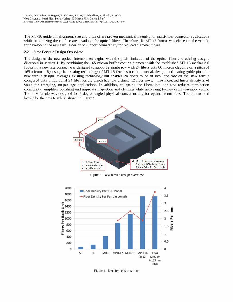
2.2 New Ferrule Design Overview
The design of the new optical interconnect begins with the pitch limitation of the optical fiber and cabling designs
discussed in section 1. By combining the 165 micron buffer coating diameter with the established MT-16 mechanical
footprint, a new interconnect was designed to support a single row with 24 fibers with 80 micron cladding on a pitch of
165 microns. By using the existing technology of MT-16 ferrules for the material, design, and mating guide pins, the
new ferrule design leverages existing technology but enables 24 fibers to be fit into one row on the new ferrule
compared with a traditional 24 fiber ferrule which has two distinct 12 fiber rows. The increased linear density is of
value for emerging, on-package applications. In addition, collapsing the fibers into one row reduces termination
complexity, simplifies polishing and improves inspection and cleaning while increasing factory cable assembly yields.
The new ferrule was designed for 8 degree angled physical contact mating for optimal return loss. The dimensional
layout for the new ferrule is shown in Figure 5.
Figure 5. New ferrule design overview
Figure 6. Density considerations

H. Asada, D. Childers, M. Hughes, T. Ishikawa, S. Lutz, D. Schoellner, K. Shindo, Y. Wada
“Next Generation Multi-Fiber Ferrule Using 165 Micron Pitch Optical Fiber”,
Photonics West Optical Interconnects XXI, SPIE, (2021). http://dx.doi.org/10.1117/12.2578649
Optical fiber density can be evaluated based on multiple metrics depending the interconnect location including fibers per
lineal space for in module or in coupling applications, fibers per ferrule cross sectional area for on-board coupling
applications and fibers per cabled connector for card edge or patch panel applications. Figure 6 compares the density of
the new ferrule for lineal space and faceplate coupling in the MPO format.
3. PHYSICAL CONTACT ANALYSIS
3.1 Physical Contact Empirical Methods
Traditional optical connectors require reliable fiber tip contact between mated connectors with no air gap. Loss of
physical contact between the fiber tips results in optical performance degradation due to Fresnel reflection effects.
Therefore, physical contact is driven by a combination of endface geometry of the ferrules, the spring force used to
compress the ferrules together, and cleanliness.
Insertion loss performance which does not match loss predicted by fiber and ferrule geometry can often be attributed to
air gaps or poor fiber tip physical contact. Proper control of the endface geometry of the ferrules is required to get all of
the fiber tips on both ferrules to make solid physical contact. With ideal endface geometry, only very low spring forces
are needed to join the fiber tips together. As endface geometry deviates from nominal, a corresponding increase in
spring force is needed to compensate for the increasing errors in geometry [8]. For multi-fiber ferrules, several key
endface geometry attributes impact physical contact performance including fiber tip coplanarity, fiber tip shape as well
as ferrule endface shape and tilt relative to alignment datums[7, 8]. As connector mating force causes the fibers to
compress, the fiber tip radius plays in important role in physical contact due to Hertzian deformation of the rounded fiber
tips [8]. Therefore, the spring force and fiber tip radii are linked together in any performance study of physical contact,
multi-fiber ferrules.
Several methods exist to determine the presence or lack of fiber tip physical contact. On average, the increase in
insertion loss due to a small airgap can be approximated to 0.3 dB, but can vary up to 0.6 dB depending on whether the
reflection creates a constructive or destructive interference pattern. It is common to verify physical contact using return
loss or back-reflection methods when high insertion loss is found. The return loss due to a Fresnel reflection on a flat
polished single mode fiber tip will be significantly less than 20dB while physical contact of mating fiber tips will result
in return loss far greater than 20dB. This return loss performance as a function of contact results in a simple
measurement method to analyze for the presence of an air gap for flat polished connectors by simply monitoring return
loss during the mating process. However, in single mode connectors with an 8 degree angle, measurement equipment is
often not sensitive enough to determine physical contact since the angled endface prevents much of the reflected light
from coupling back into the fiber core. Alternatively, if clean, physical contact is achieved, we can assume that the
insertion loss measured on a connector pair is almost entirely attributed to core offset in the alignment between the two
ferrules. Due to the mode field diameter variation as a function of wavelength, a constant ratio of insertion loss between
wavelengths at various core offsets is observed. For example, the insertion loss ratio due solely to fiber core lateral
offset at 1310nm and 1550nm with respective mode field diameters of 9.2 and 10.4 is approximately 0.78 [9]. Therefore
the resulting insertion loss ratio between wavelengths with differing mode field diameters can be used to determine
whether adequate physical contact has been achieved.
3.2 Endface geometry groups
To study physical contact requirements for this new connector and fiber, ferrules were terminated with two distinct
polishing processes designed to create distinct controlled differences in endface geometry. In both sets, coplanarity of
the fibers was minimized so that consistent mating forces and insertion losses would be maintained across all fibers.
Process A was designed to create optimal mating conditions for the fiber tips, with low coplanarity, large fiber heights,
and small fiber tip radii. Process B was designed to create less ideal mating conditions which may require higher mating
forces to establish physical contact. Process B had slightly higher coplanarity, reduced fiber heights, and larger fiber tip
radii, which would reduce the effective contact forces on the fibers and require higher spring forces to create physical
contact. Table 1 shows the average values for the two polishing processes, and Figure 7 displays the fiber heights and
fiber tip radii.

H. Asada, D. Childers, M. Hughes, T. Ishikawa, S. Lutz, D. Schoellner, K. Shindo, Y. Wada “Next Generation Multi-Fiber Ferrule Using 165 Micron Pitch Optical Fiber”,
Photonics West Optical Interconnects XXI, SPIE, (2021). http://dx.doi.org/10.1117/12.2578649
Table 1: Average endface geometry measurements for each polishing process
Process Fiber tip radius (mm) Fiber height (um) Minus coplanarity (nm)
A 0.71 1991 106.7
B 1.75 1360 113.1
Figure 7. Endface geometry for the two polishing process polulations
With two different polishing populations, connectors were intermated with similar endface geometries and insertion loss
was measured. Furthermore, in order to study physical contact requirements, the mating forces were varied as the two
populations were mated amongst themselves.
3.3 Physical Contact vs. Force
As fiber optic connectors are mated together, the springs force deformation of the ferrules, fiber and guide pins such that
physical contact between the fiber tips occurs. Insertion loss with physical contact is then a function of lateral and
angular core alignment of the mating fibers, which is governed by guide pins and holes in an MT ferrule. However, in
ferrules with angled endfaces, as the ferrules are compressed together, the angled endfaces cause the ferrules to shift
relative to each other [10]. The ferrule fiber hole position must be shifted to compensate for the y-offset translation that
occurs in the mating process. This y-offset position is based on the guide hole diameter, guide pin diameter, guide pin
pitch relationship, and the deformation constant of the MT ferrule material [10]. Since the amount of elastic deformation
will be different for different spring forces, the y-offset must be adjusted for the particular mating spring force. Single
mode angled ferrules are sensitive to changes in spring force due to the spring force impact on axial alignment. If the y-
offset is not correctly matched to the chosen spring force, the fiber cores will not align optimally, resulting in higher
insertion losses. However, as previously discussed, spring force is also directly correlated to physical contact of the fiber
tips.
In order to study spring forces required for physical contact in the new ferrules, incremental spring force was carefully
applied between 3N to 20N to determine when physical contact was achieved with respect to the two different polishing
processes. The ferrules used in this test were nominally designed with a y-offset calculated to give optimal axial
alignment with approximately 10N of mating force. The insertion loss testing with varied spring forces helps validate
both the ferrule y-offset and the physical contact of the fiber tips. Table 2 shows the average measured insertion loss as
a function of the applied spring force. For spring forces between 5N to 10N, insertion loss is very consistent and very
H. Asada, D. Childers, M. Hughes, T. Ishikawa, S. Lutz, D. Schoellner, K. Shindo, Y. Wada “Next Generation Multi-Fiber Ferrule Using 165 Micron Pitch Optical Fiber”,
Photonics West Optical Interconnects XXI, SPIE, (2021). http://dx.doi.org/10.1117/12.2578649
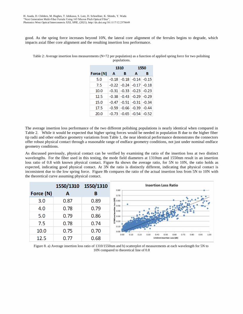
good. As the spring force increases beyond 10N, the lateral core alignment of the ferrules begins to degrade, which
impacts axial fiber core alignment and the resulting insertion loss performance.
Table 2: Average insertion loss measurements (N=72 per population) as a function of applied spring force for two polishing
populations.
The average insertion loss performance of the two different polishing populations is nearly identical when compared in
Table 2. While it would be expected that higher spring forces would be needed in population B due to the higher fiber
tip radii and other endface geometry variations from Table 1, the near identical performance demonstrates the connectors
offer robust physical contact through a reasonable range of endface geometry conditions, not just under nominal endface
geometry conditions.
As discussed previously, physical contact can be verified by examining the ratio of the insertion loss at two distinct
wavelengths. For the fiber used in this testing, the mode field diameters at 1310nm and 1550nm result in an insertion
loss ratio of 0.8 with known physical contact. Figure 8a shows the average ratio, for 5N to 10N, the ratio holds as
expected, indicating good physical contact. At 3N the ratio is distinctly different, indicating that physical contact is
inconsistent due to the low spring force. Figure 8b compares the ratio of the actual insertion loss from 5N to 10N with
the theoretical curve assuming physical contact.
Figure 8. a) Average insertion loss ratio of 1310/1550nm and b) scatterplot of measurements at each wavelength for 5N to
10N compared to theoretical line of 0.8

H. Asada, D. Childers, M. Hughes, T. Ishikawa, S. Lutz, D. Schoellner, K. Shindo, Y. Wada “Next Generation Multi-Fiber Ferrule Using 165 Micron Pitch Optical Fiber”,
Photonics West Optical Interconnects XXI, SPIE, (2021). http://dx.doi.org/10.1117/12.2578649
Back reflection Insertion loss @ 1310 nm
4. CONNECTOR PERFORMANCE
An insertion loss intermate test was performed with the two endface geometry groups. Ferrules were optimized for 10N
spring force, and a histogram of the insertion loss intermate is summarized in Figure 9a while Figure 9b shows the
typical back reflection measured during the study.
Figure 9. a) Insertion loss intermate at 1310nm and b) back reflection measurements at both 1310nm and 1550nm.
As was shown above, the insertion loss performance was similar between the two endface geometry groups described in
section 3.2. No trend of higher insertion loss on end channels indicates that the endface geometry in both groups was
sufficient for physical contact.
4.1 Environmental Performance
To evaluate the stability of the optical connection, one mated pair was subjected to thermal cycling of -40°C to 75°C
according to IEC 61753-1 category OP+. All channels were monitored for the entire 180 hours as shown in Figure 10
below.
Figure 10. Thermal cycling performance at 1310nm
H. Asada, D. Childers, M. Hughes, T. Ishikawa, S. Lutz, D. Schoellner, K. Shindo, Y. Wada
“Next Generation Multi-Fiber Ferrule Using 165 Micron Pitch Optical Fiber”,
Photonics West Optical Interconnects XXI, SPIE, (2021). http://dx.doi.org/10.1117/12.2578649
Environmental data indicates that the connection is stable throughout the temperature cycling duration. The insertion
loss increase was less than 0.26 dB on all channels easily meeting industry standard requirements. This sample test
signifies that the spring force and endface geometry for this mated pair is sufficient to maintain physical contact
throughout the thermal cycling sequence.
5. SUMMARY/CONCLUSIONS
5.1 Design, Performance, Applications
A new MT-style ferrule was developed with higher linear fiber count by using smaller pitch fiber arrays combined with
reduced cladding diameter optical fiber. By designing a ferrule for 165 micron optical fiber on a 165 micron fiber pitch
compared to the traditional 250 micron fiber pitch, the density in a single array is increased by 50%. This new ferrule
design supports emerging applications for co-packaged optics and makes use of next generation, small diameter cables
based on fibers with coating diameters less than 250 microns. The new MT-style ferrule design was molded, terminated,
and tested optically at room temperature for insertion loss and return loss performance as well as at temperature
extremes of -40 C to 75 C. In addition, the new ferrule was studied for fiber tip physical contact with varying endface
topologies and mating spring forces. Physical contact of the fiber tips was clearly achieved with reasonable factory
manufactured endface geometry specifications combined with spring forces which were below the industry normal
forces of 10N to 20N. This preliminary work indicates that MT ferrules manufactured with smaller fibers on smaller
than 250 micron pitches is viable for future high density applications.
5.2 Next Steps
The next steps for commercialization of this technology will require full reliability testing to industry standard
qualification regimens. This preliminary investigation indicates that the ferrules will perform the same as traditional MT
ferrules designed for 250 micron pitch and 125 micron optical fiber cladding diameter. While varying endface geometry
groups were trialed for this study with successful and promising results, the allowable extreme conditions for endface
geometry as a function of desired mating force must be established to create manufacturing boundary conditions.
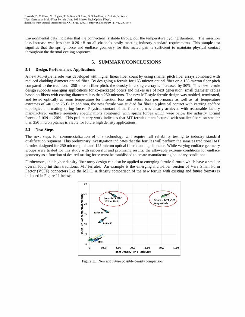
Furthermore, this higher density fiber array design can also be applied to emerging ferrule formats which have a smaller
overall footprint than traditional MT ferrules. An example is the emerging multi-fiber version of Very Small Form
Factor (VSFF) connectors like the MDC. A density comparison of the new ferrule with existing and future formats is
included in Figure 11 below.
Figure 11. New and future possible density comparison.

H. Asada, D. Childers, M. Hughes, T. Ishikawa, S. Lutz, D. Schoellner, K. Shindo, Y. Wada “Next Generation Multi-Fiber Ferrule Using 165 Micron Pitch Optical Fiber”,
Photonics West Optical Interconnects XXI, SPIE, (2021). http://dx.doi.org/10.1117/12.2578649
REFERENCES
[1] Broadcom Corporate Communications 2019, Broadcom Ships Tomahawk 4, Industry’s Highest Bandwidth Ethernet
Switch Chip at 25.6 Terabits per Second, https://www.broadcom.com/company/news/product-releases/52756,
December 9, 2019.
[2] Copackaged Optics Collaboration, Co-Packaged Optical Module Discussion Document V1.0,
http://www.copackagedoptics.com/wp-content/uploads/2019/11/CPO-Module-Discussion-Doc-V1.0Final.pdf.
[3] S. Matsuo, K. Takenaga, Y. Sakake, Y. Amma, S. Saito, K. Saitoh, T. Matsui, K. Nakajima, T. Mizuno, H. Takara, Y.
Miyamoto, T. Morioka. “High-Spatial-Multiplicity Multicore Fibers for Future Dense Space-Division-Multiplexing
System,” Journal Of Lightwave Technology, Vol. 34, No. 6, MARCH 15, 2016.
[4] G.S. Glaesemann, “Optical Fiber Mechanical Reliability; Review of Research at Corning’s Optical Fiber Strength
Laboratory,” (July, 2017).
[5] International Electrotechnical Commission (IEC), Fibre Optic Connector Interfaces - Part 5: Type MT Connector
Family, IEC 61754-5 ED. 2.0 B:2005.
[6] International Electrotechnical Commission (IEC), “Fibre Optic Interconnecting Devices And Passive Components -
Fibre Optic Connector Interfaces - Part 7-1: Type MPO Connector Family - One Fibre Row”, IEC 61754-7-1 Ed.
1.0 en:2014; “Part 7-2: Type MPO Connector Family - Two Fibre Rows”, IEC 61754-7-2 ED. 1.0 B:2017; “Part 7-
3: Type MPO Connector Family - Two Fibre Rows 16 Fibre Wide”, IEC 61754-7-3.
[7] International Electrotechnical Commission (IEC), “Fibre Optic Interconnecting Devices And Passive Components -
Connector Optical Interfaces - Part 3-31: Connector Parameters Of Non-Dispersion Shifted Single Mode Physically
Contacting Fibres - Angled Polyphenylene Sulphide Rectangular Ferrules”, IEC 61755-3-31 ED 1.0 B:2015.
[8] M. Gurreri, J. Kevern, M. Kadar-Kallen, L. Costagna, D. Childers, and M. Hughes, “Multi-Fiber, MT Ferrule
Endface Fiber Tip Displacement Model for Physical Contact Interconnects,” National Fiber Optic Engineers
Conference / Optical Society of America, (2007).
[9] Mitsuru Kihara (2012). Optical Performance Analysis of Single-Mode Fiber Connections, Optical Fiber
Communications and Devices, Dr Moh. Yasin (Ed.), ISBN: 978-953-307-954-7,
http://www.intechopen.com/books/optical-fiber-communications-and-devices/optical-performance-analysis-
ofsingle-mode-fiber-connections.
[10] T. Satake, M. Hughes, S. Lutz, D. Childers, D. Schoellner, E. Childers, and L. Hefner. “Low-Loss Intermateability
of APC-MPO Connectors between Different Material Plugs: Statistical and Experimental Study,” 59th International
Cable Connectivity Symposium, (2010).