two ferrule tube fittings - veelok needle valveveelok.com/20131030vee-lok two ferrule tube...
TRANSCRIPT

www.veelok.com
valve & fitting
Two Ferrule Tube Fittings316 stainless steel ranging from 1/8" to 1" (6mm to 25mm) O.D.

Two Ferrule Tube Fitting 1
tube fitting
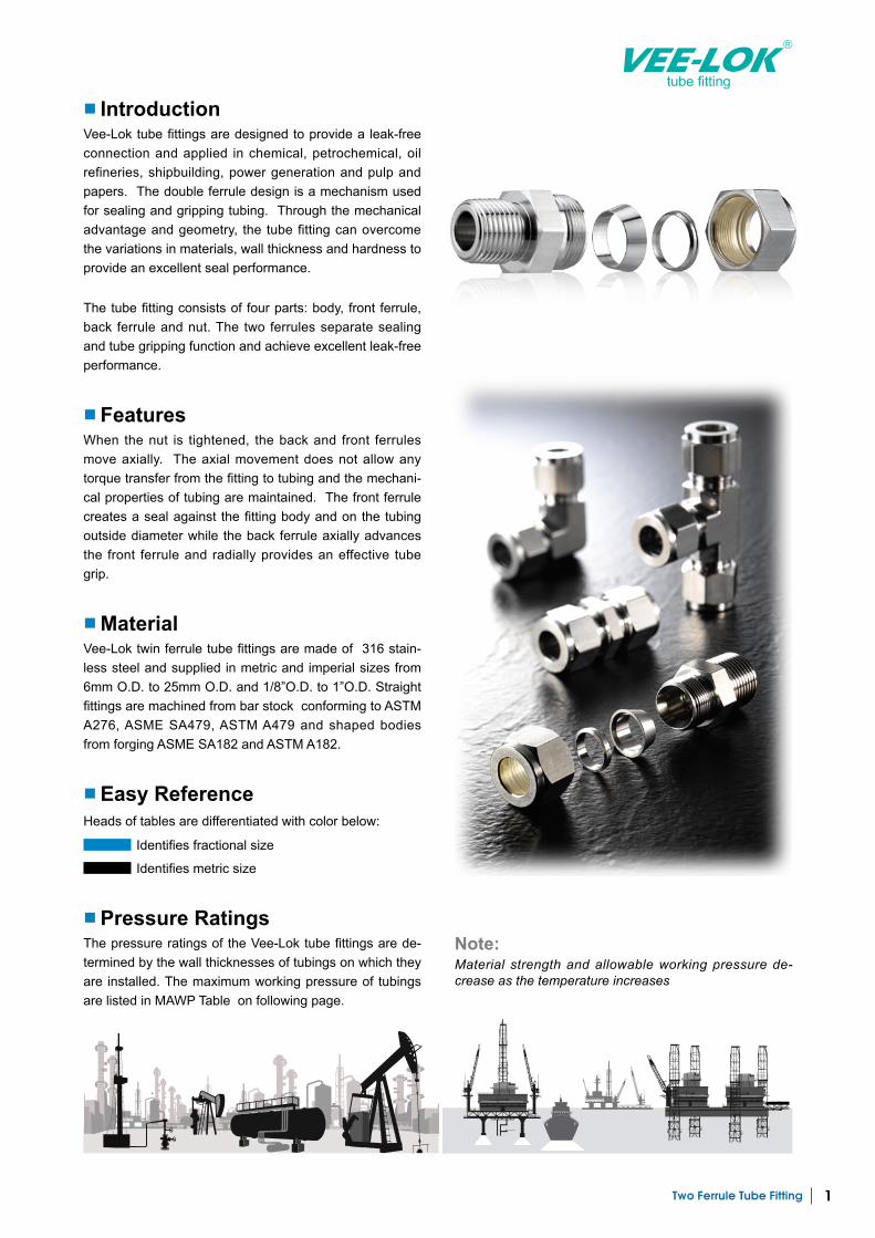
■ IntroductionVee-Lok tube fittings are designed to provide a leak-free connection and applied in chemical, petrochemical, oil refineries, shipbuilding, power generation and pulp and papers. The double ferrule design is a mechanism used for sealing and gripping tubing. Through the mechanical advantage and geometry, the tube fitting can overcome the variations in materials, wall thickness and hardness to provide an excellent seal performance.
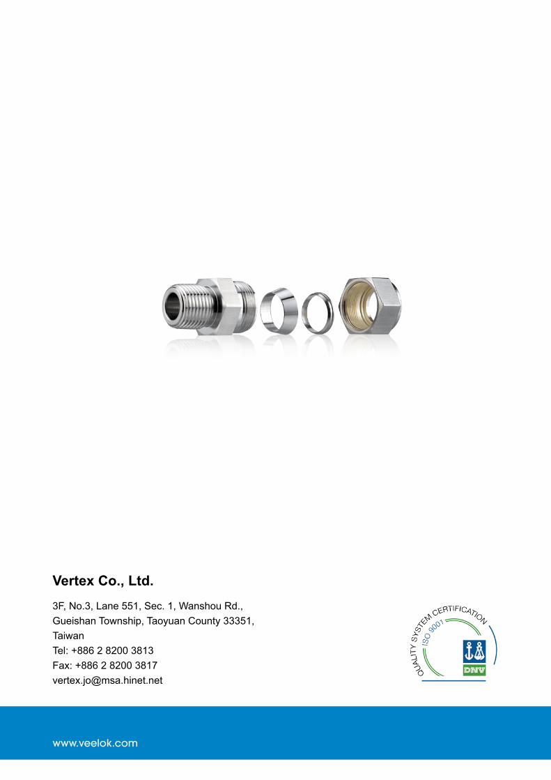
The tube fitting consists of four parts: body, front ferrule, back ferrule and nut. The two ferrules separate sealing and tube gripping function and achieve excellent leak-free performance.
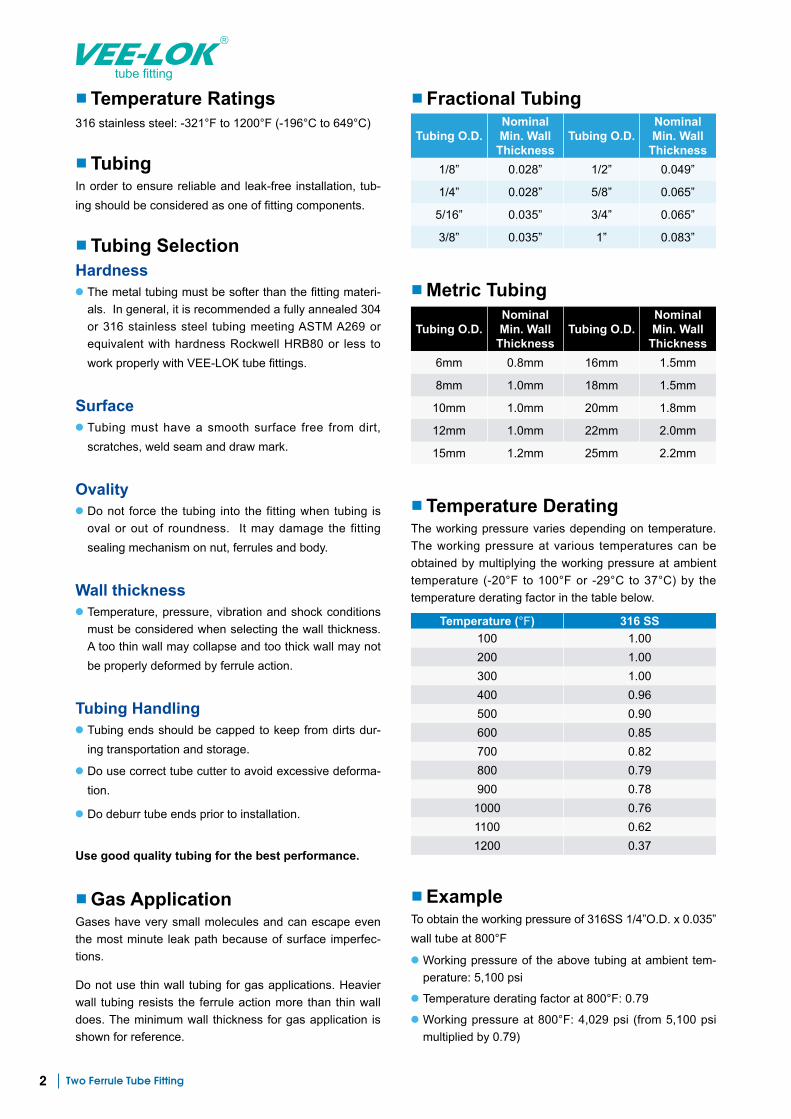
■ FeaturesWhen the nut is tightened, the back and front ferrules move axially. The axial movement does not allow any torque transfer from the fitting to tubing and the mechani-cal properties of tubing are maintained. The front ferrule creates a seal against the fitting body and on the tubing outside diameter while the back ferrule axially advances the front ferrule and radially provides an effective tube grip.
■ MaterialVee-Lok twin ferrule tube fittings are made of 316 stain-less steel and supplied in metric and imperial sizes from 6mm O.D. to 25mm O.D. and 1/8”O.D. to 1”O.D. Straight fittings are machined from bar stock conforming to ASTM A276, ASME SA479, ASTM A479 and shaped bodies from forging ASME SA182 and ASTM A182.
■ Pressure RatingsThe pressure ratings of the Vee-Lok tube fittings are de-termined by the wall thicknesses of tubings on which they are installed. The maximum working pressure of tubings are listed in MAWP Table on following page.
■ Easy ReferenceHeads of tables are differentiated with color below:
Identifies fractional size
Identifies metric size
Note:Material strength and allowable working pressure de-crease as the temperature increases
Two Ferrule Tube Fitting2
tube fitting
■ Temperature Ratings316 stainless steel: -321°F to 1200°F (-196°C to 649°C)
■ TubingIn order to ensure reliable and leak-free installation, tub-ing should be considered as one of fitting components.
■ Tubing SelectionHardness● The metal tubing must be softer than the fitting materi-
als. In general, it is recommended a fully annealed 304 or 316 stainless steel tubing meeting ASTM A269 or equivalent with hardness Rockwell HRB80 or less to work properly with VEE-LOK tube fittings.
Surface● Tubing must have a smooth surface free from dirt,
scratches, weld seam and draw mark.
Ovality● Do not force the tubing into the fitting when tubing is
oval or out of roundness. It may damage the fitting sealing mechanism on nut, ferrules and body.
Wall thickness● Temperature, pressure, vibration and shock conditions
must be considered when selecting the wall thickness. A too thin wall may collapse and too thick wall may not be properly deformed by ferrule action.
Tubing Handling● Tubing ends should be capped to keep from dirts dur-
ing transportation and storage.
● Do use correct tube cutter to avoid excessive deforma-tion.
● Do deburr tube ends prior to installation.
Use good quality tubing for the best performance.
■ Gas ApplicationGases have very small molecules and can escape even the most minute leak path because of surface imperfec-tions.
Do not use thin wall tubing for gas applications. Heavier wall tubing resists the ferrule action more than thin wall does. The minimum wall thickness for gas application is shown for reference.
■ ExampleTo obtain the working pressure of 316SS 1/4”O.D. x 0.035” wall tube at 800°F
● Working pressure of the above tubing at ambient tem-perature: 5,100 psi
● Temperature derating factor at 800°F: 0.79● Working pressure at 800°F: 4,029 psi (from 5,100 psi
multiplied by 0.79)
■ Fractional Tubing
Tubing O.D.Nominal Min. Wall
ThicknessTubing O.D.
Nominal Min. Wall
Thickness1/8” 0.028” 1/2” 0.049”
1/4” 0.028” 5/8” 0.065”
5/16” 0.035” 3/4” 0.065”
3/8” 0.035” 1” 0.083”
■ Metric Tubing
Tubing O.D.Nominal Min. Wall
ThicknessTubing O.D.
Nominal Min. Wall
Thickness6mm 0.8mm 16mm 1.5mm
8mm 1.0mm 18mm 1.5mm
10mm 1.0mm 20mm 1.8mm
12mm 1.0mm 22mm 2.0mm
15mm 1.2mm 25mm 2.2mm
■ Temperature DeratingThe working pressure varies depending on temperature. The working pressure at various temperatures can be obtained by multiplying the working pressure at ambient temperature (-20°F to 100°F or -29°C to 37°C) by the temperature derating factor in the table below.
Temperature (°F) 316 SS100 1.00200 1.00300 1.00400 0.96500 0.90600 0.85700 0.82800 0.79900 0.781000 0.761100 0.621200 0.37

Two Ferrule Tube Fitting 3
tube fitting
■ Maximum Allowable Working Pressure TableFully annealed austenitic type 304 or 316 seamless tubing ASTM A269 or ASTM A213, or equivalent. Tubing to be free from dirt, scratches, weld seam, draw mark and suitable for bending and flaring. Recommended hardness: 80 HRB or less.
● Allowable stress of 20,000 psi between -20°F and 100°F (-29°C and 37°C) based on ultimate tensile strength 75,000 psi
● Based on minimum wall thickness and maximum O.D. allowable by ASTM A269
Stainless Steel Tube Inch Size
Tube O.D. (Inches)Tube Wall Thickness in Inches
0.035 0.049 0.065 0.083
1/8” 10,900 7,500
1/4” 5,100 5,800 10,200
5/16” 4,000 4,800 8,000
3/8” 3,300 3,700 6,500
1/2” 2,600 2,400 5,100 6,700
3/4” 2,000 3,300 4,200
7/8” 2,800 3,600
1” 2,400 3,100
Stainless Steel Tube Metric Size
Tube O.D. (mm)Tube Wall Thickness in Millimeters
0.89 1.00 1.24 1.50 1.65 2.00 2.20
6 6,500 7,400 9,400 11,500 12,700
8 4,700 5,800 6,800 8,400 9,300
10 3,700 4,200 5,300 6,500 7,300
12 3,000 3,400 4,400 5,300 5,900 6,600 7,000
16 2,500 3,200 3,900 4,300 5,300 5,700
18 2,800 3,400 3,800 4,700 5,000
20 2,500 3,000 3,400 4,200 4,400
22 2,300 2,800 3,000 3,800 4,000
25 2,000 2,400 2,700 3,300 3,500
Note:1. Pressure calculations are based on maximum O.D. and minimum wall thickness without allowance for cor-
rosion and erosion.
2. Figures shown are not for design purpose but for reference only. The accuracy of information here is not liability of our company.
For gas service, applyingthe wall thickness only onoutside of shade boundary
For gas service, applyingthe wall thickness only onoutside of shade boundary
Working Pressure in psig
Working Pressure in psig
Two Ferrule Tube Fitting4
tube fitting
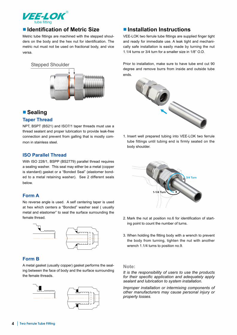
■ Identification of Metric SizeMetric tube fittings are machined with the stepped shoul-ders on the body and the hex nut for identification. The metric nut must not be used on fractional body, and vice versa.
■ SealingTaper Thread NPT, BSPT (BS21) and ISO7/1 taper threads must use a thread sealant and proper lubrication to provide leak-free connection and prevent from galling that is mostly com-mon in stainless steel.
ISO Parallel ThreadWith ISO 228/1, BSPP (BS2779) parallel thread requires a sealing washer. This seal may either be a metal (copper is standard) gasket or a “Bonded Seal” (elastomer bond-ed to a metal retaining washer). See 2 different seals below.
Form ANo reverse angle is used. A self centering taper is used at hex which centers a “Bonded” washer seal ( usually metal and elastomer” to seal the surface surrounding the female thread.
■ Installation InstructionsVEE-LOK two ferrule tube fittings are supplied finger tight and ready for immediate use. A leak tight and mechani-cally safe installation is easily made by turning the nut 1.1/4 turns or 3/4 turn for a smaller size in 1/8” O.D.
Prior to installation, make sure to have tube end cut 90 degree and remove burrs from inside and outside tube ends.
1. Insert well prepared tubing into VEE-LOK two ferrule tube fittings until tubing end is firmly seated on the body shoulder.
2. Mark the nut at position no.6 for identification of start-ing point to count the number of turns.
3. When holding the fitting body with a wrench to prevent the body from turning, tighten the nut with another wrench 1.1/4 turns to position no.9.
Form BA metal gasket (usually copper) gasket performs the seal-ing between the face of body and the surface surrounding the female threads.
Note:It is the responsibility of users to use the products for their specific application and adequately apply sealant and lubrication to system installation.
Improper installation or intermixing components of other manufacturers may cause personal injury or property losses.
12
9
6
3 3/4 Turn
1-1/4 Turn
Two Ferrule Tube Fitting 5
tube fitting
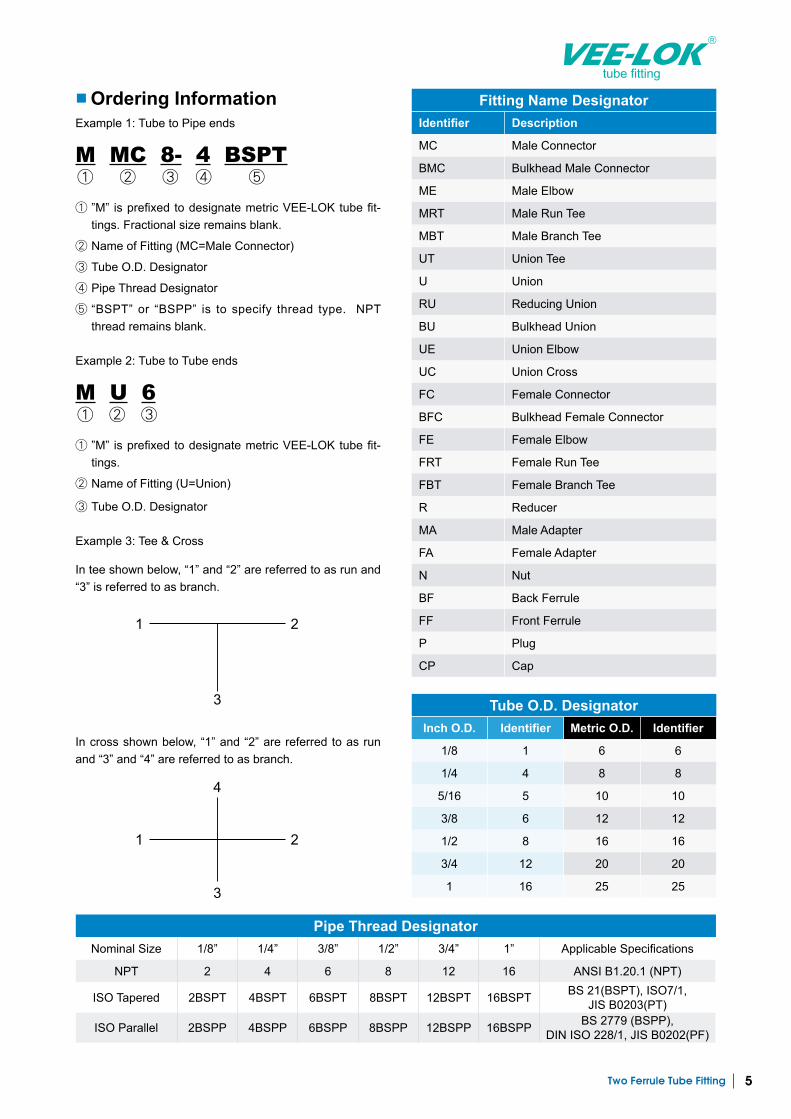
■ Ordering InformationExample 1: Tube to Pipe ends
M MC 8- 4 BSPT① ② ③ ④ ⑤
① ”M” is prefixed to designate metric VEE-LOK tube fit-tings. Fractional size remains blank.
② Name of Fitting (MC=Male Connector)
③ Tube O.D. Designator
④ Pipe Thread Designator
⑤ “BSPT” or “BSPP” is to specify thread type. NPT thread remains blank.
Example 2: Tube to Tube ends
M U 6① ② ③
① ”M” is prefixed to designate metric VEE-LOK tube fit-tings.
② Name of Fitting (U=Union)
③ Tube O.D. Designator
Example 3: Tee & Cross
In tee shown below, “1” and “2” are referred to as run and “3” is referred to as branch.
In cross shown below, “1” and “2” are referred to as run and “3” and “4” are referred to as branch.
Fitting Name DesignatorIdentifier Description
MC Male Connector
BMC Bulkhead Male Connector
ME Male Elbow
MRT Male Run Tee
MBT Male Branch Tee
UT Union Tee
U Union
RU Reducing Union
BU Bulkhead Union
UE Union Elbow
UC Union Cross
FC Female Connector
BFC Bulkhead Female Connector
FE Female Elbow
FRT Female Run Tee
FBT Female Branch Tee
R Reducer
MA Male Adapter
FA Female Adapter
N Nut
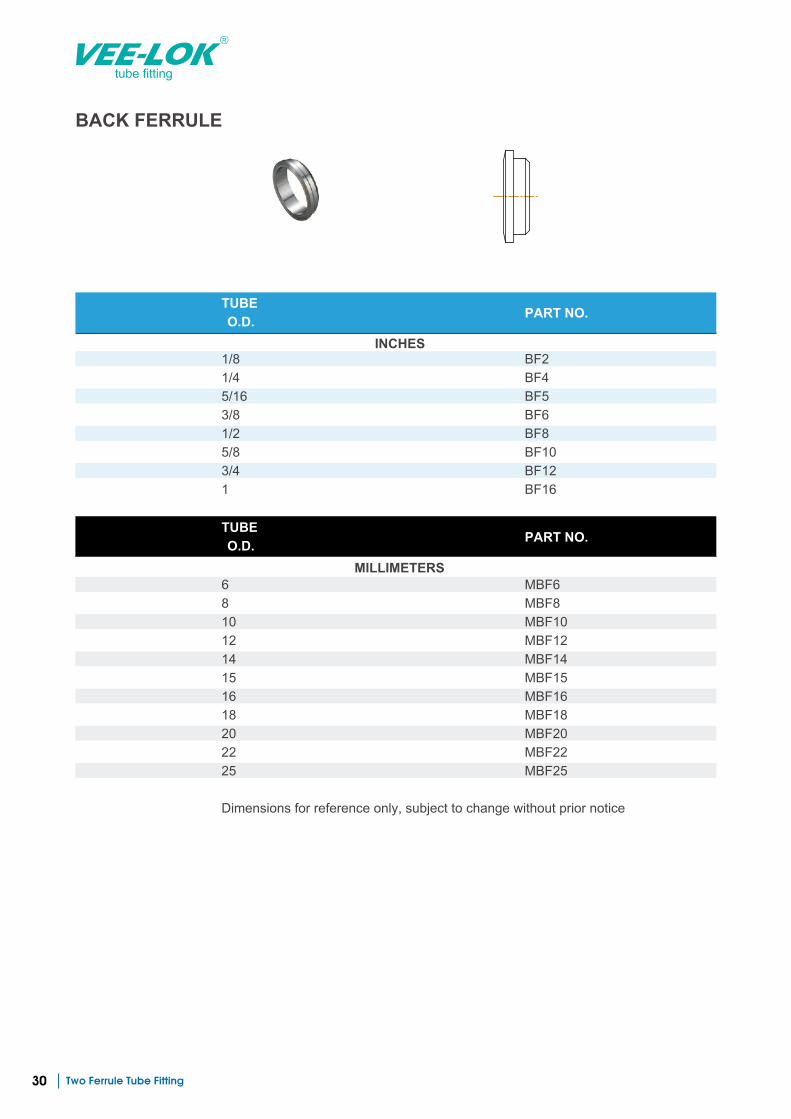
BF Back Ferrule
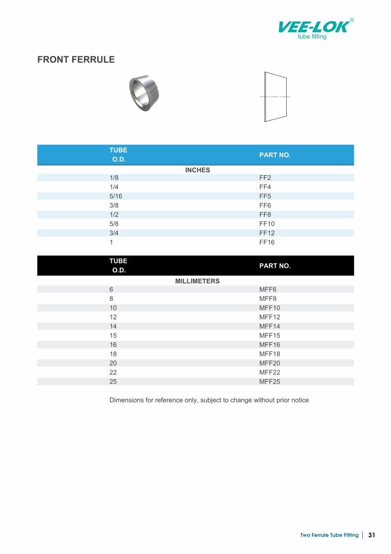
FF Front Ferrule
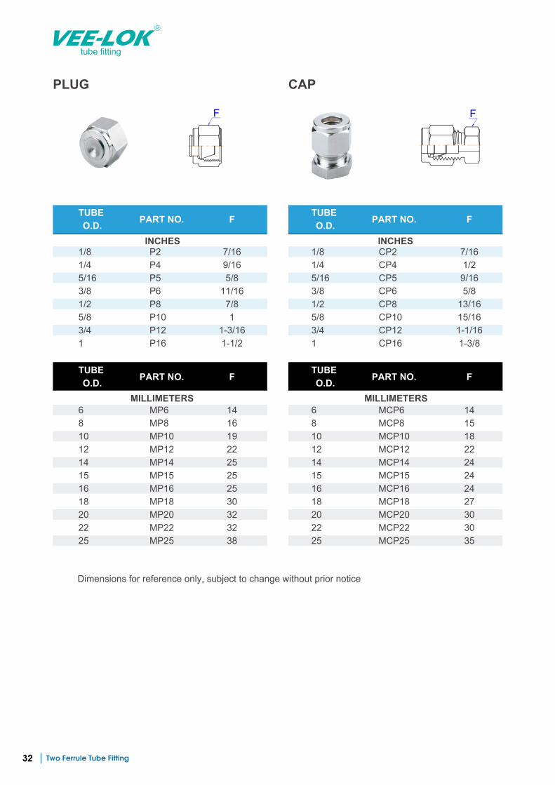
P Plug
CP Cap
Tube O.D. DesignatorInch O.D. Identifier Metric O.D. Identifier
1/8 1 6 6
1/4 4 8 8
5/16 5 10 10
3/8 6 12 12
1/2 8 16 16
3/4 12 20 20
1 16 25 25
Pipe Thread DesignatorNominal Size 1/8” 1/4” 3/8” 1/2” 3/4” 1” Applicable Specifications
NPT 2 4 6 8 12 16 ANSI B1.20.1 (NPT)
ISO Tapered 2BSPT 4BSPT 6BSPT 8BSPT 12BSPT 16BSPT BS 21(BSPT), ISO7/1,JIS B0203(PT)
ISO Parallel 2BSPP 4BSPP 6BSPP 8BSPP 12BSPP 16BSPP BS 2779 (BSPP),DIN ISO 228/1, JIS B0202(PF)
1 2
3
1 2
4
3
Two Ferrule Tube Fitting6
tube fitting
Tube to Male Pipe
Tube to Female Pipe
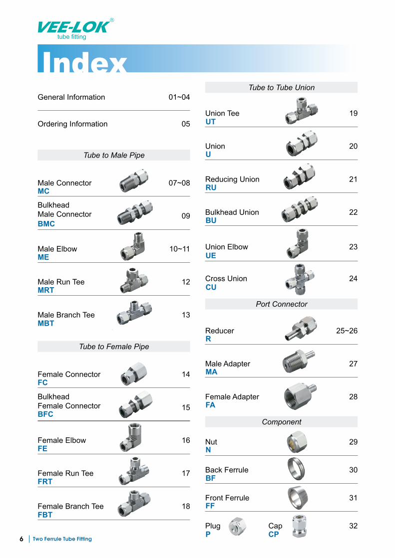
General Information 01~04
Ordering Information 05
Male Connector 07~08
Female Connector 14
09BulkheadMale Connector
15BulkheadFemale Connector
Male Elbow 10~11
Female Elbow 16
Male Run Tee 12
Female Run Tee 17
Male Branch Tee 13
Female Branch Tee 18
MC
ME
Port Connector
Component
Tube to Tube Union
Union Tee 19
Union 20
Reducing Union 21
Reducer 25~26
Bulkhead Union 22
Male Adapter 27
Union Elbow 23
Cross Union 24
Female Adapter 28
Nut 29
Back Ferrule 30
Front Ferrule 31
UT
U
RU
BU
UE
CU
R
MA
FA
N
BF
FF
Plug 32P
CapCP
MRT
MBT
FC
FE
FRT
FBT
BFC
BMC
Two Ferrule Tube Fitting 7
tube fitting
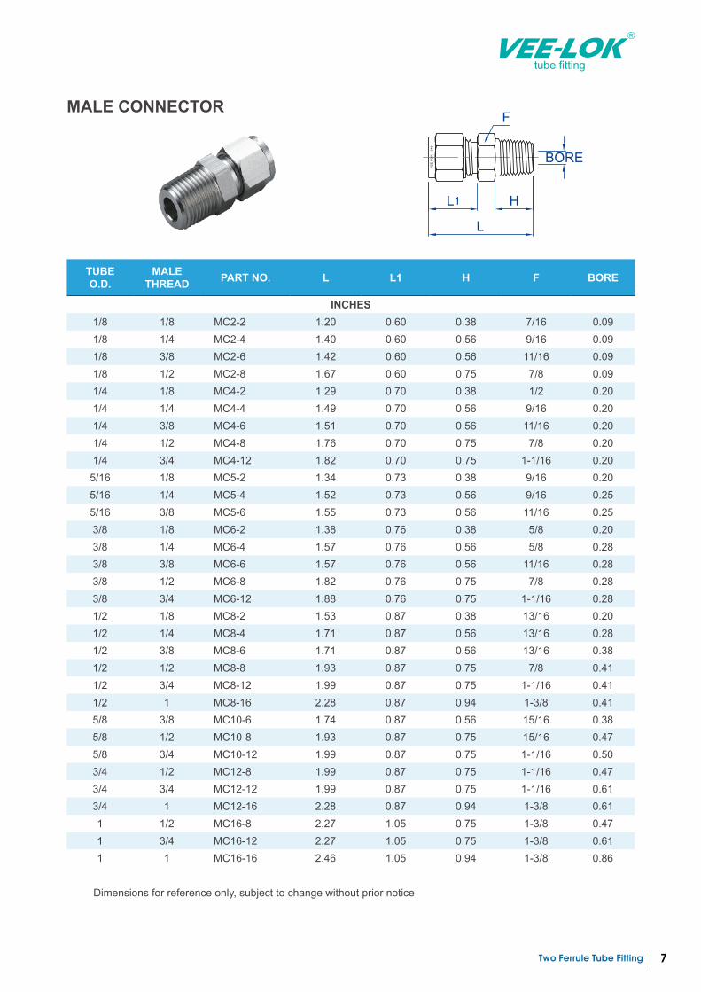
MALE CONNECTOR
TUBEO.D.
MALE THREAD PART NO. L L1 H F BORE
INCHES1/8 1/8 MC2-2 1.20 0.60 0.38 7/16 0.09 1/8 1/4 MC2-4 1.40 0.60 0.56 9/16 0.09 1/8 3/8 MC2-6 1.42 0.60 0.56 11/16 0.09 1/8 1/2 MC2-8 1.67 0.60 0.75 7/8 0.09 1/4 1/8 MC4-2 1.29 0.70 0.38 1/2 0.20 1/4 1/4 MC4-4 1.49 0.70 0.56 9/16 0.20 1/4 3/8 MC4-6 1.51 0.70 0.56 11/16 0.20 1/4 1/2 MC4-8 1.76 0.70 0.75 7/8 0.20 1/4 3/4 MC4-12 1.82 0.70 0.75 1-1/16 0.20
5/16 1/8 MC5-2 1.34 0.73 0.38 9/16 0.20 5/16 1/4 MC5-4 1.52 0.73 0.56 9/16 0.25 5/16 3/8 MC5-6 1.55 0.73 0.56 11/16 0.25 3/8 1/8 MC6-2 1.38 0.76 0.38 5/8 0.20 3/8 1/4 MC6-4 1.57 0.76 0.56 5/8 0.28 3/8 3/8 MC6-6 1.57 0.76 0.56 11/16 0.28 3/8 1/2 MC6-8 1.82 0.76 0.75 7/8 0.28 3/8 3/4 MC6-12 1.88 0.76 0.75 1-1/16 0.28 1/2 1/8 MC8-2 1.53 0.87 0.38 13/16 0.20 1/2 1/4 MC8-4 1.71 0.87 0.56 13/16 0.28 1/2 3/8 MC8-6 1.71 0.87 0.56 13/16 0.38 1/2 1/2 MC8-8 1.93 0.87 0.75 7/8 0.41 1/2 3/4 MC8-12 1.99 0.87 0.75 1-1/16 0.41 1/2 1 MC8-16 2.28 0.87 0.94 1-3/8 0.41 5/8 3/8 MC10-6 1.74 0.87 0.56 15/16 0.38 5/8 1/2 MC10-8 1.93 0.87 0.75 15/16 0.47 5/8 3/4 MC10-12 1.99 0.87 0.75 1-1/16 0.50 3/4 1/2 MC12-8 1.99 0.87 0.75 1-1/16 0.47 3/4 3/4 MC12-12 1.99 0.87 0.75 1-1/16 0.61 3/4 1 MC12-16 2.28 0.87 0.94 1-3/8 0.61 1 1/2 MC16-8 2.27 1.05 0.75 1-3/8 0.47 1 3/4 MC16-12 2.27 1.05 0.75 1-3/8 0.61 1 1 MC16-16 2.46 1.05 0.94 1-3/8 0.86
Dimensions for reference only, subject to change without prior notice
VE
E-L
OK
3
16
L1
L
H
BORE
F
Two Ferrule Tube Fitting8
tube fitting
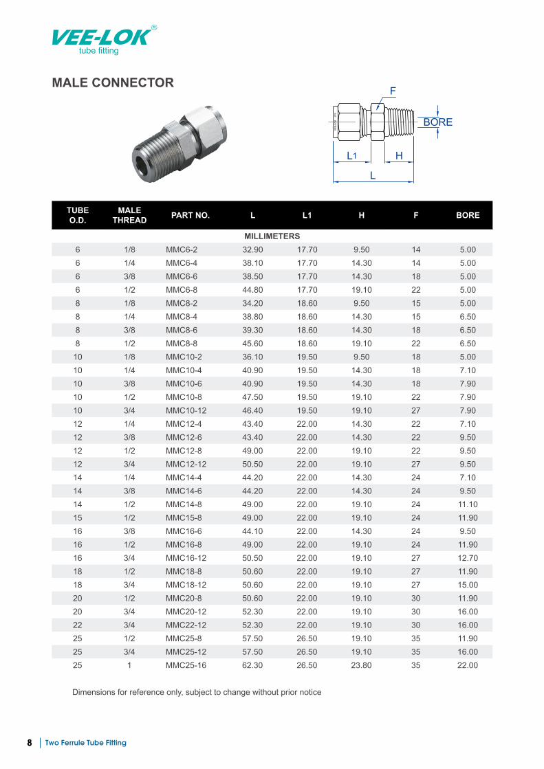
MALE CONNECTOR
VE
E-L
OK
3
16
L1
L
H
BORE
F
TUBEO.D.
MALE THREAD PART NO. L L1 H F BORE
MILLIMETERS6 1/8 MMC6-2 32.90 17.70 9.50 14 5.00 6 1/4 MMC6-4 38.10 17.70 14.30 14 5.00 6 3/8 MMC6-6 38.50 17.70 14.30 18 5.00 6 1/2 MMC6-8 44.80 17.70 19.10 22 5.00 8 1/8 MMC8-2 34.20 18.60 9.50 15 5.00 8 1/4 MMC8-4 38.80 18.60 14.30 15 6.50 8 3/8 MMC8-6 39.30 18.60 14.30 18 6.50 8 1/2 MMC8-8 45.60 18.60 19.10 22 6.50
10 1/8 MMC10-2 36.10 19.50 9.50 18 5.00 10 1/4 MMC10-4 40.90 19.50 14.30 18 7.10 10 3/8 MMC10-6 40.90 19.50 14.30 18 7.90 10 1/2 MMC10-8 47.50 19.50 19.10 22 7.90 10 3/4 MMC10-12 46.40 19.50 19.10 27 7.90 12 1/4 MMC12-4 43.40 22.00 14.30 22 7.10 12 3/8 MMC12-6 43.40 22.00 14.30 22 9.50 12 1/2 MMC12-8 49.00 22.00 19.10 22 9.50 12 3/4 MMC12-12 50.50 22.00 19.10 27 9.50 14 1/4 MMC14-4 44.20 22.00 14.30 24 7.10 14 3/8 MMC14-6 44.20 22.00 14.30 24 9.50 14 1/2 MMC14-8 49.00 22.00 19.10 24 11.10 15 1/2 MMC15-8 49.00 22.00 19.10 24 11.90 16 3/8 MMC16-6 44.10 22.00 14.30 24 9.50 16 1/2 MMC16-8 49.00 22.00 19.10 24 11.90 16 3/4 MMC16-12 50.50 22.00 19.10 27 12.70 18 1/2 MMC18-8 50.60 22.00 19.10 27 11.90 18 3/4 MMC18-12 50.60 22.00 19.10 27 15.00 20 1/2 MMC20-8 50.60 22.00 19.10 30 11.90 20 3/4 MMC20-12 52.30 22.00 19.10 30 16.00 22 3/4 MMC22-12 52.30 22.00 19.10 30 16.00 25 1/2 MMC25-8 57.50 26.50 19.10 35 11.90 25 3/4 MMC25-12 57.50 26.50 19.10 35 16.00 25 1 MMC25-16 62.30 26.50 23.80 35 22.00
Dimensions for reference only, subject to change without prior notice
Two Ferrule Tube Fitting 9
tube fitting
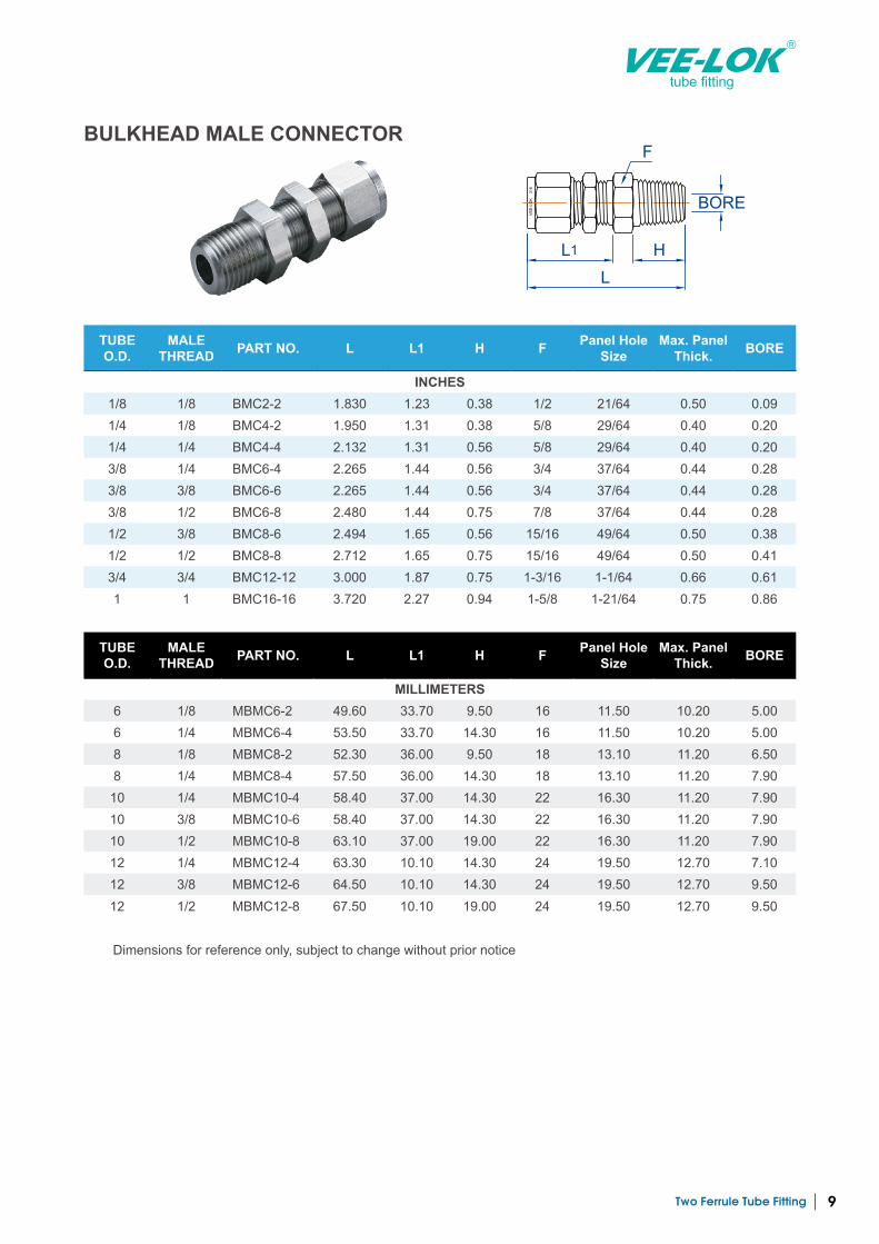
BULKHEAD MALE CONNECTOR
TUBE O.D.
MALE THREAD PART NO. L L1 H F Panel Hole
SizeMax. Panel
Thick. BORE
INCHES1/8 1/8 BMC2-2 1.830 1.23 0.38 1/2 21/64 0.50 0.09 1/4 1/8 BMC4-2 1.950 1.31 0.38 5/8 29/64 0.40 0.20 1/4 1/4 BMC4-4 2.132 1.31 0.56 5/8 29/64 0.40 0.20 3/8 1/4 BMC6-4 2.265 1.44 0.56 3/4 37/64 0.44 0.28 3/8 3/8 BMC6-6 2.265 1.44 0.56 3/4 37/64 0.44 0.28 3/8 1/2 BMC6-8 2.480 1.44 0.75 7/8 37/64 0.44 0.28 1/2 3/8 BMC8-6 2.494 1.65 0.56 15/16 49/64 0.50 0.38 1/2 1/2 BMC8-8 2.712 1.65 0.75 15/16 49/64 0.50 0.41 3/4 3/4 BMC12-12 3.000 1.87 0.75 1-3/16 1-1/64 0.66 0.61 1 1 BMC16-16 3.720 2.27 0.94 1-5/8 1-21/64 0.75 0.86
VE
E-L
OK
3
16
L1
L
H
BORE
F
TUBE O.D.
MALE THREAD PART NO. L L1 H F Panel Hole
SizeMax. Panel
Thick. BORE
MILLIMETERS6 1/8 MBMC6-2 49.60 33.70 9.50 16 11.50 10.20 5.00 6 1/4 MBMC6-4 53.50 33.70 14.30 16 11.50 10.20 5.00 8 1/8 MBMC8-2 52.30 36.00 9.50 18 13.10 11.20 6.50 8 1/4 MBMC8-4 57.50 36.00 14.30 18 13.10 11.20 7.90
10 1/4 MBMC10-4 58.40 37.00 14.30 22 16.30 11.20 7.90 10 3/8 MBMC10-6 58.40 37.00 14.30 22 16.30 11.20 7.90 10 1/2 MBMC10-8 63.10 37.00 19.00 22 16.30 11.20 7.90 12 1/4 MBMC12-4 63.30 10.10 14.30 24 19.50 12.70 7.10 12 3/8 MBMC12-6 64.50 10.10 14.30 24 19.50 12.70 9.50 12 1/2 MBMC12-8 67.50 10.10 19.00 24 19.50 12.70 9.50
Dimensions for reference only, subject to change without prior notice
Two Ferrule Tube Fitting10
tube fitting
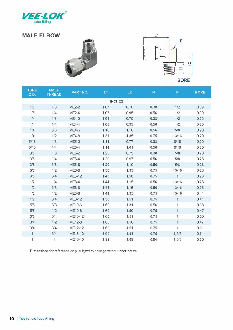
MALE ELBOW
TUBE O.D.
MALE THREAD PART NO. L1 L2 H F BORE
INCHES1/8 1/8 ME2-2 1.07 0.70 0.38 1/2 0.09 1/8 1/4 ME2-4 1.07 0.95 0.56 1/2 0.09 1/4 1/8 ME4-2 1.08 0.70 0.38 1/2 0.20 1/4 1/4 ME4-4 1.08 0.95 0.56 1/2 0.20 1/4 3/8 ME4-6 1.16 1.10 0.56 5/8 0.20 1/4 1/2 ME4-8 1.31 1.35 0.75 13/16 0.20 5/16 1/8 ME5-2 1.14 0.77 0.38 9/16 0.20 5/16 1/4 ME5-4 1.14 1.01 0.56 9/16 0.25 3/8 1/8 ME6-2 1.20 0.79 0.38 5/8 0.20 3/8 1/4 ME6-4 1.20 0.97 0.56 5/8 0.28 3/8 3/8 ME6-6 1.20 1.10 0.56 5/8 0.28 3/8 1/2 ME6-8 1.36 1.35 0.75 13/16 0.28 3/8 3/4 ME6-12 1.48 1.50 0.75 1 0.28 1/2 1/4 ME8-4 1.44 1.15 0.56 13/16 0.28 1/2 3/8 ME8-6 1.44 1.15 0.56 13/16 0.38 1/2 1/2 ME8-8 1.44 1.35 0.75 13/16 0.41 1/2 3/4 ME8-12 1.58 1.51 0.75 1 0.41 5/8 3/8 ME10-6 1.60 1.31 0.56 1 0.38 5/8 1/2 ME10-8 1.60 1.50 0.75 1 0.47 5/8 3/4 ME10-12 1.60 1.51 0.75 1 0.50 3/4 1/2 ME12-8 1.60 1.50 0.75 1 0.47 3/4 3/4 ME12-12 1.60 1.51 0.75 1 0.61 1 3/4 ME16-12 1.99 1.81 0.75 1-3/8 0.61 1 1 ME16-16 1.99 1.89 0.94 1-3/8 0.86
Dimensions for reference only, subject to change without prior notice
VE
E-L
OK
3
16
L1
H
L2
F
BORE
Two Ferrule Tube Fitting 11
tube fitting
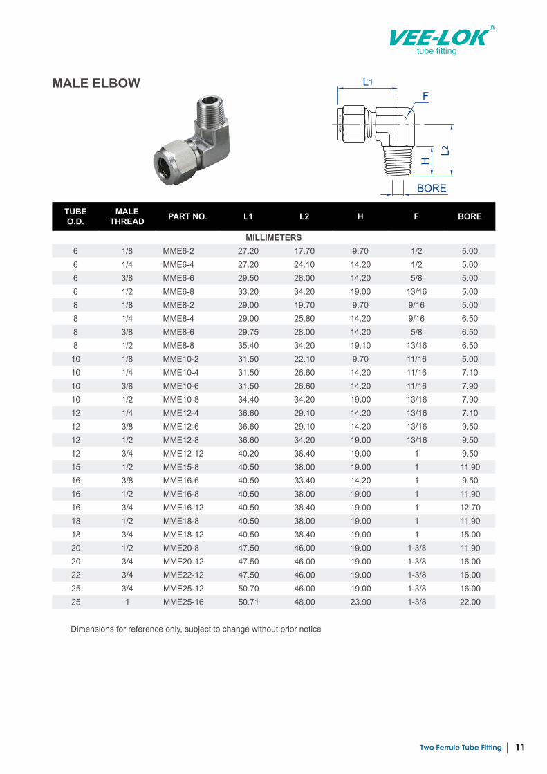
MALE ELBOW
VE
E-L
OK
3
16
L1
H
L2
F
BORE
TUBE O.D.
MALE THREAD PART NO. L1 L2 H F BORE
MILLIMETERS6 1/8 MME6-2 27.20 17.70 9.70 1/2 5.00 6 1/4 MME6-4 27.20 24.10 14.20 1/2 5.00 6 3/8 MME6-6 29.50 28.00 14.20 5/8 5.00 6 1/2 MME6-8 33.20 34.20 19.00 13/16 5.00 8 1/8 MME8-2 29.00 19.70 9.70 9/16 5.00 8 1/4 MME8-4 29.00 25.80 14.20 9/16 6.50 8 3/8 MME8-6 29.75 28.00 14.20 5/8 6.50 8 1/2 MME8-8 35.40 34.20 19.10 13/16 6.50 10 1/8 MME10-2 31.50 22.10 9.70 11/16 5.00 10 1/4 MME10-4 31.50 26.60 14.20 11/16 7.10 10 3/8 MME10-6 31.50 26.60 14.20 11/16 7.90 10 1/2 MME10-8 34.40 34.20 19.00 13/16 7.90 12 1/4 MME12-4 36.60 29.10 14.20 13/16 7.10 12 3/8 MME12-6 36.60 29.10 14.20 13/16 9.50 12 1/2 MME12-8 36.60 34.20 19.00 13/16 9.50 12 3/4 MME12-12 40.20 38.40 19.00 1 9.50 15 1/2 MME15-8 40.50 38.00 19.00 1 11.90 16 3/8 MME16-6 40.50 33.40 14.20 1 9.50 16 1/2 MME16-8 40.50 38.00 19.00 1 11.90 16 3/4 MME16-12 40.50 38.40 19.00 1 12.70 18 1/2 MME18-8 40.50 38.00 19.00 1 11.90 18 3/4 MME18-12 40.50 38.40 19.00 1 15.00 20 1/2 MME20-8 47.50 46.00 19.00 1-3/8 11.90 20 3/4 MME20-12 47.50 46.00 19.00 1-3/8 16.00 22 3/4 MME22-12 47.50 46.00 19.00 1-3/8 16.00 25 3/4 MME25-12 50.70 46.00 19.00 1-3/8 16.00 25 1 MME25-16 50.71 48.00 23.90 1-3/8 22.00
Dimensions for reference only, subject to change without prior notice
Two Ferrule Tube Fitting12
tube fitting
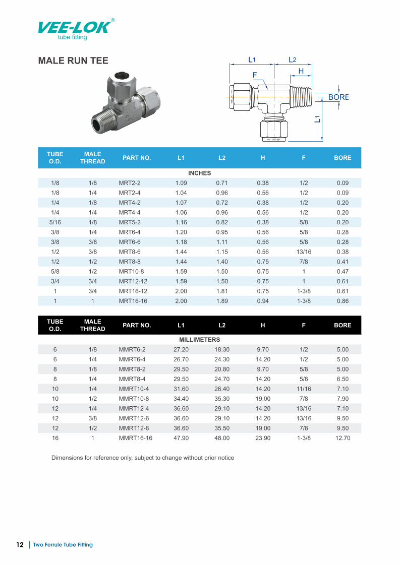
MALE RUN TEE
VE
E-L
OK
3
16
VEE-LOK 316
H
L2L1
BORE
L1
F
TUBE O.D.
MALE THREAD PART NO. L1 L2 H F BORE
INCHES1/8 1/8 MRT2-2 1.09 0.71 0.38 1/2 0.09 1/8 1/4 MRT2-4 1.04 0.96 0.56 1/2 0.09 1/4 1/8 MRT4-2 1.07 0.72 0.38 1/2 0.20 1/4 1/4 MRT4-4 1.06 0.96 0.56 1/2 0.20 5/16 1/8 MRT5-2 1.16 0.82 0.38 5/8 0.20 3/8 1/4 MRT6-4 1.20 0.95 0.56 5/8 0.28 3/8 3/8 MRT6-6 1.18 1.11 0.56 5/8 0.28 1/2 3/8 MRT8-6 1.44 1.15 0.56 13/16 0.38 1/2 1/2 MRT8-8 1.44 1.40 0.75 7/8 0.41 5/8 1/2 MRT10-8 1.59 1.50 0.75 1 0.47 3/4 3/4 MRT12-12 1.59 1.50 0.75 1 0.61 1 3/4 MRT16-12 2.00 1.81 0.75 1-3/8 0.61 1 1 MRT16-16 2.00 1.89 0.94 1-3/8 0.86
TUBE O.D.
MALE THREAD PART NO. L1 L2 H F BORE
MILLIMETERS6 1/8 MMRT6-2 27.20 18.30 9.70 1/2 5.00 6 1/4 MMRT6-4 26.70 24.30 14.20 1/2 5.00 8 1/8 MMRT8-2 29.50 20.80 9.70 5/8 5.00 8 1/4 MMRT8-4 29.50 24.70 14.20 5/8 6.50 10 1/4 MMRT10-4 31.60 26.40 14.20 11/16 7.10 10 1/2 MMRT10-8 34.40 35.30 19.00 7/8 7.90 12 1/4 MMRT12-4 36.60 29.10 14.20 13/16 7.10 12 3/8 MMRT12-6 36.60 29.10 14.20 13/16 9.50 12 1/2 MMRT12-8 36.60 35.50 19.00 7/8 9.50 16 1 MMRT16-16 47.90 48.00 23.90 1-3/8 12.70
Dimensions for reference only, subject to change without prior notice
Two Ferrule Tube Fitting 13
tube fitting
TUBE O.D.
MALE THREAD PART NO. L L1 L2 H F BORE
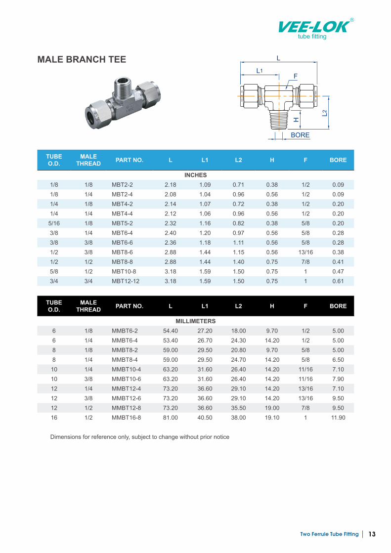
INCHES1/8 1/8 MBT2-2 2.18 1.09 0.71 0.38 1/2 0.09 1/8 1/4 MBT2-4 2.08 1.04 0.96 0.56 1/2 0.09 1/4 1/8 MBT4-2 2.14 1.07 0.72 0.38 1/2 0.20 1/4 1/4 MBT4-4 2.12 1.06 0.96 0.56 1/2 0.20
5/16 1/8 MBT5-2 2.32 1.16 0.82 0.38 5/8 0.20 3/8 1/4 MBT6-4 2.40 1.20 0.97 0.56 5/8 0.28 3/8 3/8 MBT6-6 2.36 1.18 1.11 0.56 5/8 0.28 1/2 3/8 MBT8-6 2.88 1.44 1.15 0.56 13/16 0.38 1/2 1/2 MBT8-8 2.88 1.44 1.40 0.75 7/8 0.41 5/8 1/2 MBT10-8 3.18 1.59 1.50 0.75 1 0.47 3/4 3/4 MBT12-12 3.18 1.59 1.50 0.75 1 0.61
MALE BRANCH TEEV
EE
-LOK
316
VE
E-L
OK
3
16
L1
L
F
H
L2
BORE
TUBE O.D.
MALE THREAD PART NO. L L1 L2 H F BORE
MILLIMETERS6 1/8 MMBT6-2 54.40 27.20 18.00 9.70 1/2 5.00 6 1/4 MMBT6-4 53.40 26.70 24.30 14.20 1/2 5.00 8 1/8 MMBT8-2 59.00 29.50 20.80 9.70 5/8 5.00 8 1/4 MMBT8-4 59.00 29.50 24.70 14.20 5/8 6.50
10 1/4 MMBT10-4 63.20 31.60 26.40 14.20 11/16 7.10 10 3/8 MMBT10-6 63.20 31.60 26.40 14.20 11/16 7.90 12 1/4 MMBT12-4 73.20 36.60 29.10 14.20 13/16 7.10 12 3/8 MMBT12-6 73.20 36.60 29.10 14.20 13/16 9.50 12 1/2 MMBT12-8 73.20 36.60 35.50 19.00 7/8 9.50 16 1/2 MMBT16-8 81.00 40.50 38.00 19.10 1 11.90
Dimensions for reference only, subject to change without prior notice
Two Ferrule Tube Fitting14
tube fitting
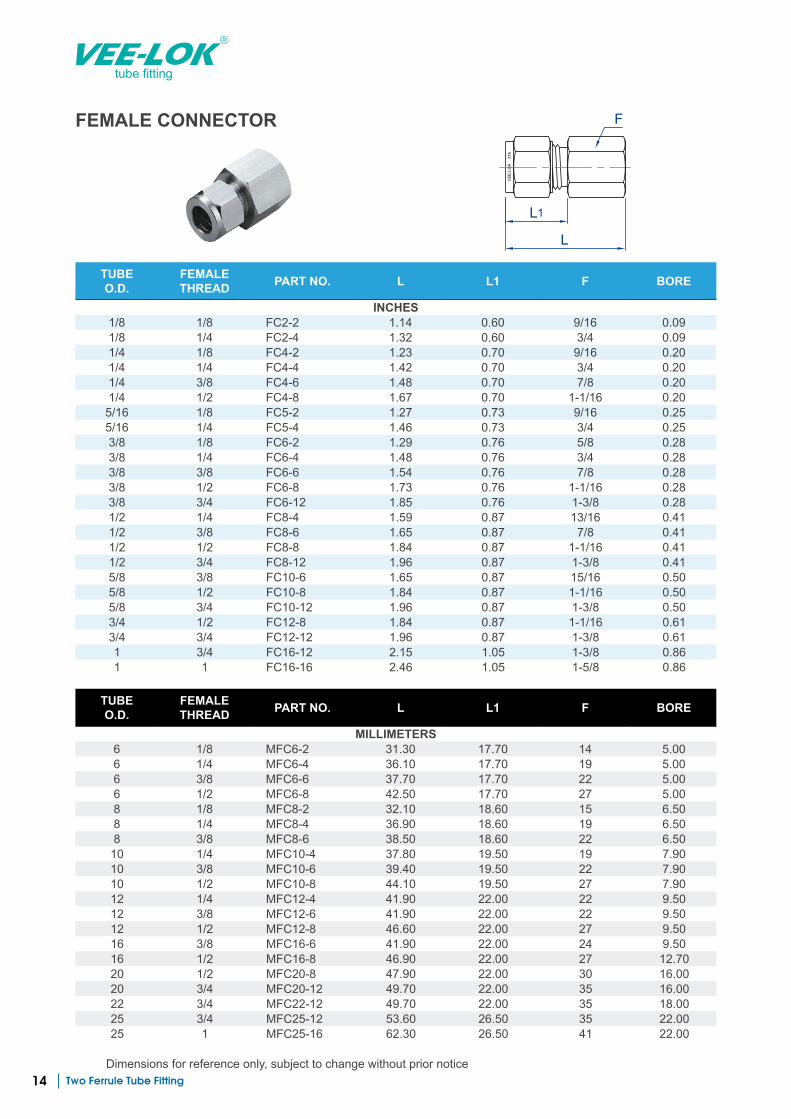
FEMALE CONNECTOR
TUBE O.D.
FEMALE THREAD PART NO. L L1 F BORE
INCHES1/8 1/8 FC2-2 1.14 0.60 9/16 0.09 1/8 1/4 FC2-4 1.32 0.60 3/4 0.09 1/4 1/8 FC4-2 1.23 0.70 9/16 0.20 1/4 1/4 FC4-4 1.42 0.70 3/4 0.20 1/4 3/8 FC4-6 1.48 0.70 7/8 0.20 1/4 1/2 FC4-8 1.67 0.70 1-1/16 0.20 5/16 1/8 FC5-2 1.27 0.73 9/16 0.25 5/16 1/4 FC5-4 1.46 0.73 3/4 0.25 3/8 1/8 FC6-2 1.29 0.76 5/8 0.28 3/8 1/4 FC6-4 1.48 0.76 3/4 0.28 3/8 3/8 FC6-6 1.54 0.76 7/8 0.28 3/8 1/2 FC6-8 1.73 0.76 1-1/16 0.28 3/8 3/4 FC6-12 1.85 0.76 1-3/8 0.28 1/2 1/4 FC8-4 1.59 0.87 13/16 0.41 1/2 3/8 FC8-6 1.65 0.87 7/8 0.41 1/2 1/2 FC8-8 1.84 0.87 1-1/16 0.41 1/2 3/4 FC8-12 1.96 0.87 1-3/8 0.41 5/8 3/8 FC10-6 1.65 0.87 15/16 0.50 5/8 1/2 FC10-8 1.84 0.87 1-1/16 0.50 5/8 3/4 FC10-12 1.96 0.87 1-3/8 0.50 3/4 1/2 FC12-8 1.84 0.87 1-1/16 0.61 3/4 3/4 FC12-12 1.96 0.87 1-3/8 0.61 1 3/4 FC16-12 2.15 1.05 1-3/8 0.86 1 1 FC16-16 2.46 1.05 1-5/8 0.86
VE
E-L
OK
3
16
L1
L
F
TUBE O.D.
FEMALE THREAD PART NO. L L1 F BORE
MILLIMETERS6 1/8 MFC6-2 31.30 17.70 14 5.00 6 1/4 MFC6-4 36.10 17.70 19 5.00 6 3/8 MFC6-6 37.70 17.70 22 5.00 6 1/2 MFC6-8 42.50 17.70 27 5.00 8 1/8 MFC8-2 32.10 18.60 15 6.50 8 1/4 MFC8-4 36.90 18.60 19 6.50 8 3/8 MFC8-6 38.50 18.60 22 6.50 10 1/4 MFC10-4 37.80 19.50 19 7.90 10 3/8 MFC10-6 39.40 19.50 22 7.90 10 1/2 MFC10-8 44.10 19.50 27 7.90 12 1/4 MFC12-4 41.90 22.00 22 9.50 12 3/8 MFC12-6 41.90 22.00 22 9.50 12 1/2 MFC12-8 46.60 22.00 27 9.50 16 3/8 MFC16-6 41.90 22.00 24 9.50 16 1/2 MFC16-8 46.90 22.00 27 12.70 20 1/2 MFC20-8 47.90 22.00 30 16.00 20 3/4 MFC20-12 49.70 22.00 35 16.00 22 3/4 MFC22-12 49.70 22.00 35 18.00 25 3/4 MFC25-12 53.60 26.50 35 22.00 25 1 MFC25-16 62.30 26.50 41 22.00
Dimensions for reference only, subject to change without prior notice
Two Ferrule Tube Fitting 15
tube fitting
VE
E-L
OK
3
16
L1
L
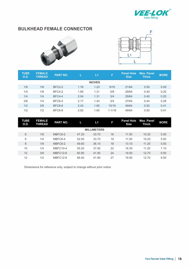
FBULKHEAD FEMALE CONNECTOR
TUBE O.D.
FEMALE THREAD PART NO. L L1 F Panel Hole
SizeMax. Panel
Thick. BORE
INCHES1/8 1/8 BFC2-2 1.76 1.23 9/16 21/64 0.50 0.09 1/4 1/8 BFC4-2 1.85 1.31 5/8 29/64 0.40 0.20 1/4 1/4 BFC4-4 2.04 1.31 3/4 29/64 0.40 0.20 3/8 1/4 BFC6-4 2.17 1.44 3/4 37/64 0.44 0.28 1/2 3/8 BFC8-6 2.43 1.65 15/16 49/64 0.50 0.41 1/2 1/2 BFC8-8 2.62 1.65 1-1/16 49/64 0.50 0.41
TUBE O.D.
FEMALE THREAD PART NO. L L1 F Panel Hole
SizeMax. Panel
Thick. BORE
MILLIMETERS6 1/8 MBFC6-2 47.20 33.70 16 11.50 10.20 5.00 6 1/4 MBFC6-4 52.00 33.70 19 11.50 10.20 5.00 8 1/8 MBFC8-2 49.60 36.10 18 13.10 11.20 5.00
10 1/4 MBFC10-4 55.20 37.00 22 16.30 11.20 7.10 12 3/8 MBFC12-6 60.90 41.90 24 19.50 12.70 9.50 12 1/2 MBFC12-8 66.40 41.90 27 19.50 12.70 9.50
Dimensions for reference only, subject to change without prior notice
Two Ferrule Tube Fitting16
tube fitting
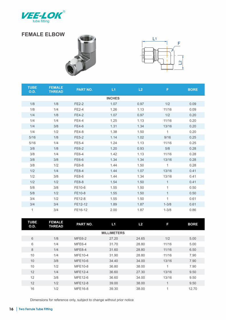
FEMALE ELBOW
VE
E-L
OK
3
16
L1
L2
F
TUBE O.D.
FEMALE THREAD PART NO. L1 L2 F BORE
INCHES1/8 1/8 FE2-2 1.07 0.97 1/2 0.09 1/8 1/4 FE2-4 1.26 1.13 11/16 0.09 1/4 1/8 FE4-2 1.07 0.97 1/2 0.20 1/4 1/4 FE4-4 1.25 1.13 11/16 0.20 1/4 3/8 FE4-6 1.31 1.34 13/16 0.20 1/4 1/2 FE4-8 1.38 1.50 1 0.20
5/16 1/8 FE5-2 1.14 1.02 9/16 0.25 5/16 1/4 FE5-4 1.24 1.13 11/16 0.25 3/8 1/8 FE6-2 1.20 0.93 5/8 0.28 3/8 1/4 FE6-4 1.42 1.13 11/16 0.28 3/8 3/8 FE6-6 1.34 1.34 13/16 0.28 3/8 1/2 FE6-8 1.44 1.50 1 0.28 1/2 1/4 FE8-4 1.44 1.07 13/16 0.41 1/2 3/8 FE8-6 1.44 1.34 13/16 0.41 1/2 1/2 FE8-8 1.54 1.50 1 0.41 5/8 3/8 FE10-6 1.55 1.50 1 0.50 5/8 1/2 FE10-8 1.55 1.50 1 0.50 3/4 1/2 FE12-8 1.55 1.50 1 0.61 3/4 3/4 FE12-12 1.89 1.87 1-3/8 0.61 1 3/4 FE16-12 2.00 1.87 1-3/8 0.86
TUBE O.D.
FEMALE THREAD PART NO. L1 L2 F BORE
MILLIMETERS6 1/8 MFE6-2 27.20 24.65 1/2 5.00 6 1/4 MFE6-4 31.70 28.80 11/16 5.00 8 1/4 MFE8-4 31.60 28.80 11/16 6.50 10 1/4 MFE10-4 31.90 28.80 11/16 7.90 10 3/8 MFE10-6 34.40 34.00 13/16 7.90 10 1/2 MFE10-8 36.80 38.00 1 7.90 12 1/4 MFE12-4 36.60 27.30 13/16 9.50 12 3/8 MFE12-6 36.60 34.00 13/16 9.50 12 1/2 MFE12-8 39.00 38.00 1 9.50 16 1/2 MFE16-8 39.30 38.00 1 12.70
Dimensions for reference only, subject to change without prior notice
Two Ferrule Tube Fitting 17
tube fitting
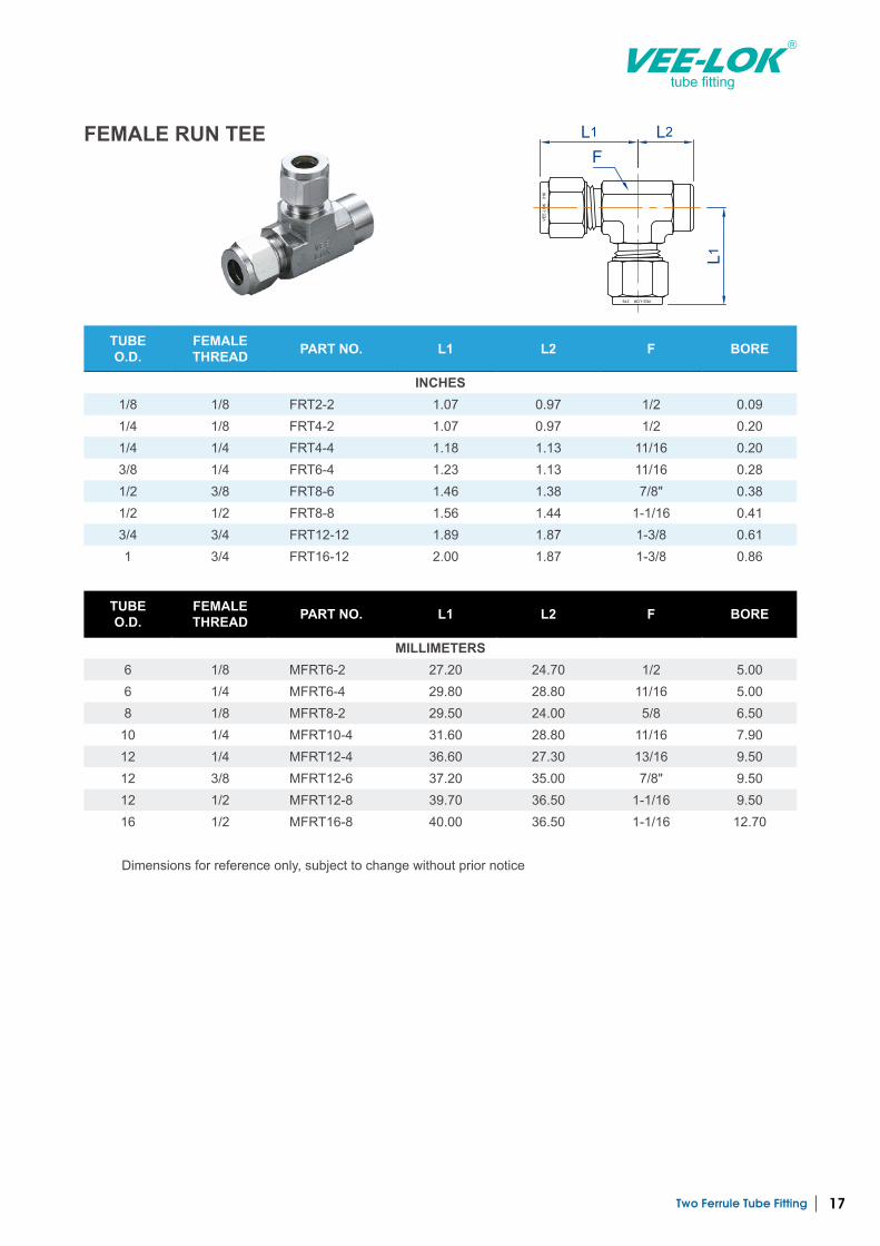
TUBE O.D.
FEMALE THREAD PART NO. L1 L2 F BORE
INCHES1/8 1/8 FRT2-2 1.07 0.97 1/2 0.09 1/4 1/8 FRT4-2 1.07 0.97 1/2 0.20 1/4 1/4 FRT4-4 1.18 1.13 11/16 0.20 3/8 1/4 FRT6-4 1.23 1.13 11/16 0.28 1/2 3/8 FRT8-6 1.46 1.38 7/8" 0.38 1/2 1/2 FRT8-8 1.56 1.44 1-1/16 0.41 3/4 3/4 FRT12-12 1.89 1.87 1-3/8 0.61 1 3/4 FRT16-12 2.00 1.87 1-3/8 0.86
FEMALE RUN TEE
VE
E-L
OK
3
16
VEE-LOK 316
L1 L2
L1
F
TUBE O.D.
FEMALE THREAD PART NO. L1 L2 F BORE
MILLIMETERS6 1/8 MFRT6-2 27.20 24.70 1/2 5.00 6 1/4 MFRT6-4 29.80 28.80 11/16 5.00 8 1/8 MFRT8-2 29.50 24.00 5/8 6.50
10 1/4 MFRT10-4 31.60 28.80 11/16 7.90 12 1/4 MFRT12-4 36.60 27.30 13/16 9.50 12 3/8 MFRT12-6 37.20 35.00 7/8" 9.50 12 1/2 MFRT12-8 39.70 36.50 1-1/16 9.50 16 1/2 MFRT16-8 40.00 36.50 1-1/16 12.70
Dimensions for reference only, subject to change without prior notice
Two Ferrule Tube Fitting18
tube fitting
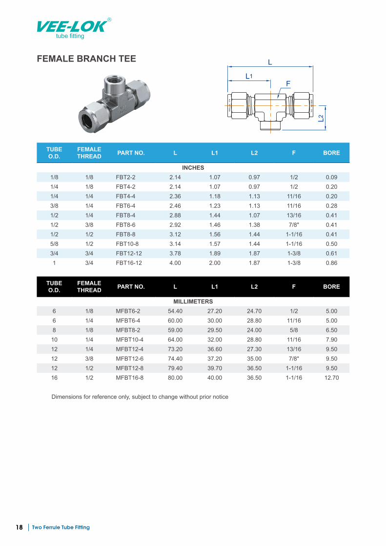
TUBE O.D.
FEMALE THREAD PART NO. L L1 L2 F BORE
INCHES1/8 1/8 FBT2-2 2.14 1.07 0.97 1/2 0.09 1/4 1/8 FBT4-2 2.14 1.07 0.97 1/2 0.20 1/4 1/4 FBT4-4 2.36 1.18 1.13 11/16 0.20 3/8 1/4 FBT6-4 2.46 1.23 1.13 11/16 0.28 1/2 1/4 FBT8-4 2.88 1.44 1.07 13/16 0.41 1/2 3/8 FBT8-6 2.92 1.46 1.38 7/8" 0.41 1/2 1/2 FBT8-8 3.12 1.56 1.44 1-1/16 0.41 5/8 1/2 FBT10-8 3.14 1.57 1.44 1-1/16 0.50 3/4 3/4 FBT12-12 3.78 1.89 1.87 1-3/8 0.61 1 3/4 FBT16-12 4.00 2.00 1.87 1-3/8 0.86
FEMALE BRANCH TEE
VE
E-L
OK
3
16
VE
E-LO
K 316
L1
L
L2
F
TUBE O.D.
FEMALE THREAD PART NO. L L1 L2 F BORE
MILLIMETERS6 1/8 MFBT6-2 54.40 27.20 24.70 1/2 5.00 6 1/4 MFBT6-4 60.00 30.00 28.80 11/16 5.00 8 1/8 MFBT8-2 59.00 29.50 24.00 5/8 6.50 10 1/4 MFBT10-4 64.00 32.00 28.80 11/16 7.90 12 1/4 MFBT12-4 73.20 36.60 27.30 13/16 9.50 12 3/8 MFBT12-6 74.40 37.20 35.00 7/8" 9.50 12 1/2 MFBT12-8 79.40 39.70 36.50 1-1/16 9.50 16 1/2 MFBT16-8 80.00 40.00 36.50 1-1/16 12.70
Dimensions for reference only, subject to change without prior notice
Two Ferrule Tube Fitting 19
tube fitting
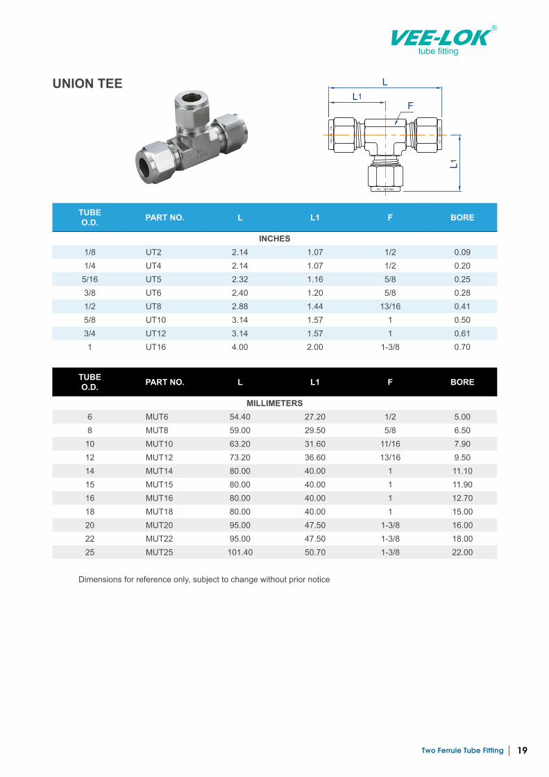
UNION TEE
VE
E-L
OK
3
16
VE
E-LO
K 316
VEE-LOK 316
L1
L
L1
F
TUBE O.D. PART NO. L L1 F BORE
INCHES1/8 UT2 2.14 1.07 1/2 0.09 1/4 UT4 2.14 1.07 1/2 0.20
5/16 UT5 2.32 1.16 5/8 0.25 3/8 UT6 2.40 1.20 5/8 0.28 1/2 UT8 2.88 1.44 13/16 0.41 5/8 UT10 3.14 1.57 1 0.50 3/4 UT12 3.14 1.57 1 0.61 1 UT16 4.00 2.00 1-3/8 0.70
TUBE O.D. PART NO. L L1 F BORE
MILLIMETERS6 MUT6 54.40 27.20 1/2 5.00 8 MUT8 59.00 29.50 5/8 6.50 10 MUT10 63.20 31.60 11/16 7.90 12 MUT12 73.20 36.60 13/16 9.50 14 MUT14 80.00 40.00 1 11.10 15 MUT15 80.00 40.00 1 11.90 16 MUT16 80.00 40.00 1 12.70 18 MUT18 80.00 40.00 1 15.00 20 MUT20 95.00 47.50 1-3/8 16.00 22 MUT22 95.00 47.50 1-3/8 18.00 25 MUT25 101.40 50.70 1-3/8 22.00
Dimensions for reference only, subject to change without prior notice
Two Ferrule Tube Fitting20
tube fitting
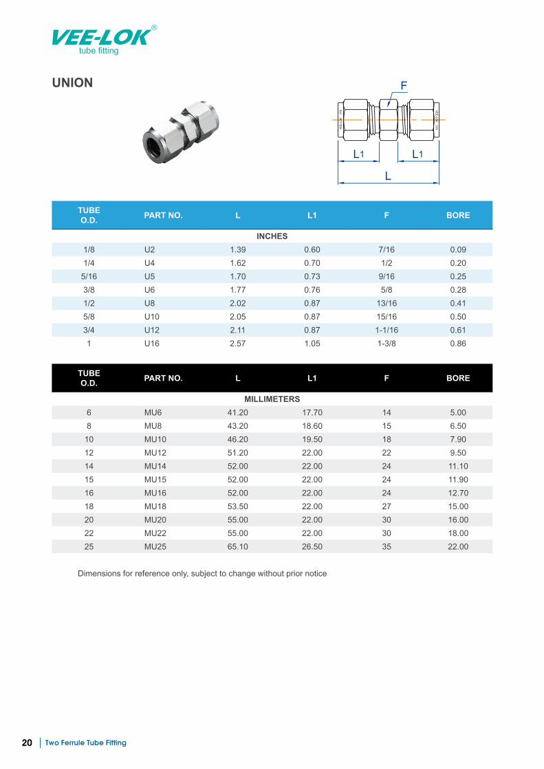
UNION
VE
E-L
OK
3
16
VE
E-LO
K 316
L1
L
L1
F
TUBE O.D. PART NO. L L1 F BORE
INCHES1/8 U2 1.39 0.60 7/16 0.09 1/4 U4 1.62 0.70 1/2 0.20
5/16 U5 1.70 0.73 9/16 0.25 3/8 U6 1.77 0.76 5/8 0.28 1/2 U8 2.02 0.87 13/16 0.41 5/8 U10 2.05 0.87 15/16 0.50 3/4 U12 2.11 0.87 1-1/16 0.61 1 U16 2.57 1.05 1-3/8 0.86
TUBE O.D. PART NO. L L1 F BORE
MILLIMETERS6 MU6 41.20 17.70 14 5.00 8 MU8 43.20 18.60 15 6.50
10 MU10 46.20 19.50 18 7.90 12 MU12 51.20 22.00 22 9.50 14 MU14 52.00 22.00 24 11.10 15 MU15 52.00 22.00 24 11.90 16 MU16 52.00 22.00 24 12.70 18 MU18 53.50 22.00 27 15.00 20 MU20 55.00 22.00 30 16.00 22 MU22 55.00 22.00 30 18.00 25 MU25 65.10 26.50 35 22.00
Dimensions for reference only, subject to change without prior notice
Two Ferrule Tube Fitting 21
tube fitting
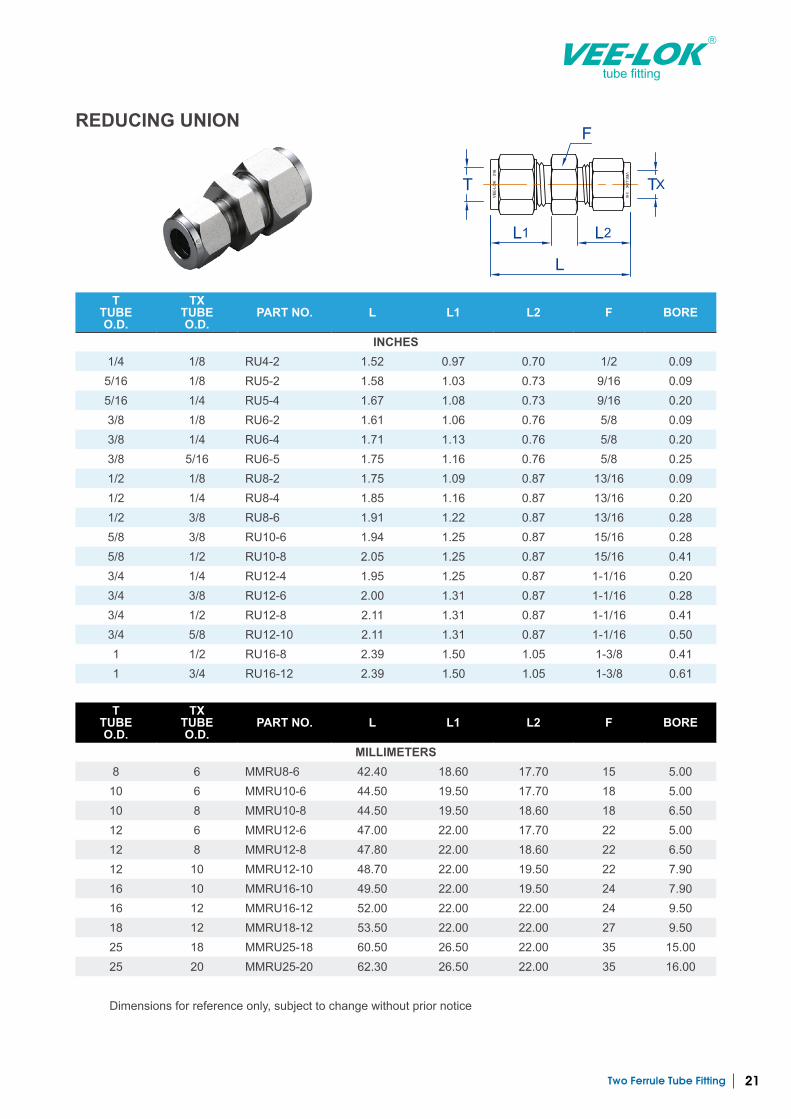
REDUCING UNION
VE
E-L
OK
3
16
VE
E-LO
K 316
L1
L
L2
F
TXT
T TUBE O.D.
TX TUBE O.D.
PART NO. L L1 L2 F BORE
INCHES1/4 1/8 RU4-2 1.52 0.97 0.70 1/2 0.09 5/16 1/8 RU5-2 1.58 1.03 0.73 9/16 0.09 5/16 1/4 RU5-4 1.67 1.08 0.73 9/16 0.20 3/8 1/8 RU6-2 1.61 1.06 0.76 5/8 0.09 3/8 1/4 RU6-4 1.71 1.13 0.76 5/8 0.20 3/8 5/16 RU6-5 1.75 1.16 0.76 5/8 0.25 1/2 1/8 RU8-2 1.75 1.09 0.87 13/16 0.09 1/2 1/4 RU8-4 1.85 1.16 0.87 13/16 0.20 1/2 3/8 RU8-6 1.91 1.22 0.87 13/16 0.28 5/8 3/8 RU10-6 1.94 1.25 0.87 15/16 0.28 5/8 1/2 RU10-8 2.05 1.25 0.87 15/16 0.41 3/4 1/4 RU12-4 1.95 1.25 0.87 1-1/16 0.20 3/4 3/8 RU12-6 2.00 1.31 0.87 1-1/16 0.28 3/4 1/2 RU12-8 2.11 1.31 0.87 1-1/16 0.41 3/4 5/8 RU12-10 2.11 1.31 0.87 1-1/16 0.50 1 1/2 RU16-8 2.39 1.50 1.05 1-3/8 0.41 1 3/4 RU16-12 2.39 1.50 1.05 1-3/8 0.61
T TUBE O.D.
TX TUBE O.D.
PART NO. L L1 L2 F BORE
MILLIMETERS8 6 MMRU8-6 42.40 18.60 17.70 15 5.00 10 6 MMRU10-6 44.50 19.50 17.70 18 5.00 10 8 MMRU10-8 44.50 19.50 18.60 18 6.50 12 6 MMRU12-6 47.00 22.00 17.70 22 5.00 12 8 MMRU12-8 47.80 22.00 18.60 22 6.50 12 10 MMRU12-10 48.70 22.00 19.50 22 7.90 16 10 MMRU16-10 49.50 22.00 19.50 24 7.90 16 12 MMRU16-12 52.00 22.00 22.00 24 9.50 18 12 MMRU18-12 53.50 22.00 22.00 27 9.50 25 18 MMRU25-18 60.50 26.50 22.00 35 15.00 25 20 MMRU25-20 62.30 26.50 22.00 35 16.00
Dimensions for reference only, subject to change without prior notice
Two Ferrule Tube Fitting22
tube fitting
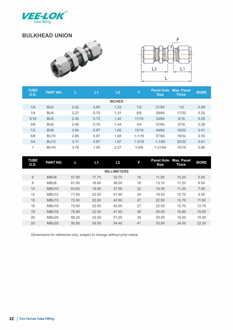
BULKHEAD UNION
VE
E-L
OK
3
16
VE
E-LO
K 316
VE
E-LO
K 316
L2
L
L1
F
TUBE O.D. PART NO. L L1 L2 F Panel Hole
SizeMax. Panel
Thick. BORE
INCHES1/8 BU2 2.02 0.60 1.23 1/2 21/64 1/2 0.09 1/4 BU4 2.27 0.70 1.31 5/8 29/64 17/32 0.20 5/16 BU5 2.40 0.73 1.42 11/16 33/64 9/16 0.25 3/8 BU6 2.46 0.76 1.44 3/4 37/64 9/16 0.28 1/2 BU8 2.80 0.87 1.65 15/16 49/64 19/32 0.41 5/8 BU10 2.86 0.87 1.68 1-1/16 57/64 19/32 0.50 3/4 BU12 3.11 0.87 1.87 1-3/16 1-1/64 25/32 0.61 1 BU16 3.78 1.05 2.27 1-5/8 1-21/64 15/16 0.86
TUBE O.D. PART NO. L L1 L2 F Panel Hole
SizeMax. Panel
Thick. BORE
MILLIMETERS6 MBU6 57.90 17.70 33.70 16 11.50 10.20 5.00 8 MBU8 61.00 18.60 36.00 18 13.10 11.20 6.50 10 MBU10 63.60 19.50 37.00 22 16.30 11.20 7.90 12 MBU12 71.00 22.00 41.90 24 19.50 12.70 9.50 15 MBU15 72.50 22.00 42.60 27 22.50 12.70 11.90 16 MBU16 72.60 22.00 42.60 27 22.50 12.70 12.70 18 MBU18 78.90 22.00 47.40 30 26.00 16.80 15.00 20 MBU20 88.20 22.00 51.00 35 29.00 19.00 16.00 25 MBU25 95.80 26.50 54.40 41 33.80 24.00 22.00
Dimensions for reference only, subject to change without prior notice
Two Ferrule Tube Fitting 23
tube fitting
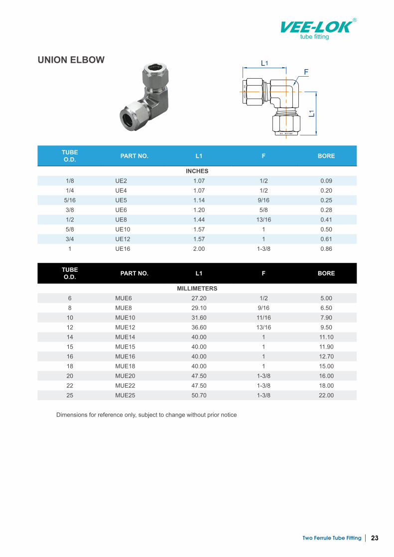
UNION ELBOW
VE
E-L
OK
3
16
VEE-LOK 316
L1
L1
F
TUBE O.D. PART NO. L1 F BORE
INCHES1/8 UE2 1.07 1/2 0.09 1/4 UE4 1.07 1/2 0.20 5/16 UE5 1.14 9/16 0.25 3/8 UE6 1.20 5/8 0.28 1/2 UE8 1.44 13/16 0.41 5/8 UE10 1.57 1 0.50 3/4 UE12 1.57 1 0.61 1 UE16 2.00 1-3/8 0.86
TUBE O.D. PART NO. L1 F BORE
MILLIMETERS6 MUE6 27.20 1/2 5.00 8 MUE8 29.10 9/16 6.50 10 MUE10 31.60 11/16 7.90 12 MUE12 36.60 13/16 9.50 14 MUE14 40.00 1 11.10 15 MUE15 40.00 1 11.90 16 MUE16 40.00 1 12.70 18 MUE18 40.00 1 15.00 20 MUE20 47.50 1-3/8 16.00 22 MUE22 47.50 1-3/8 18.00 25 MUE25 50.70 1-3/8 22.00
Dimensions for reference only, subject to change without prior notice
Two Ferrule Tube Fitting24
tube fitting
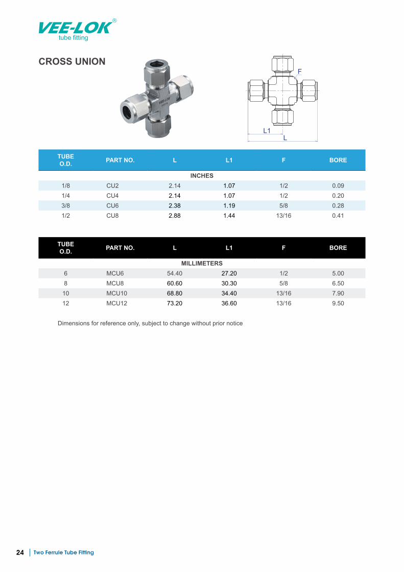
CROSS UNION
L1L
F
TUBE O.D. PART NO. L L1 F BORE
INCHES1/8 CU2 2.14 1.07 1/2 0.09 1/4 CU4 2.14 1.07 1/2 0.20 3/8 CU6 2.38 1.19 5/8 0.28 1/2 CU8 2.88 1.44 13/16 0.41
TUBE O.D. PART NO. L L1 F BORE
MILLIMETERS6 MCU6 54.40 27.20 1/2 5.00 8 MCU8 60.60 30.30 5/8 6.50
10 MCU10 68.80 34.40 13/16 7.90 12 MCU12 73.20 36.60 13/16 9.50
Dimensions for reference only, subject to change without prior notice
Two Ferrule Tube Fitting 25
tube fitting
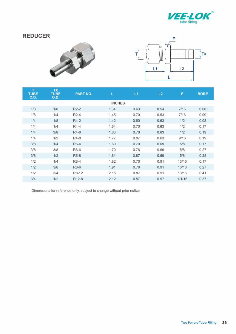
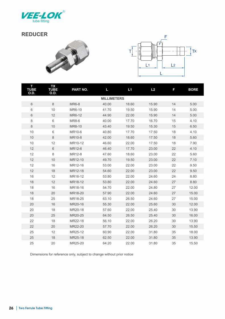
REDUCER
VE
E-L
OK
3
16
L1
L
L2
T TX
F
T TUBE O.D.
TX TUBE O.D.
PART NO. L L1 L2 F BORE
INCHES1/8 1/8 R2-2 1.34 0.43 0.54 7/16 0.08 1/8 1/4 R2-4 1.45 0.70 0.53 7/16 0.09 1/4 1/8 R4-2 1.42 0.60 0.63 1/2 0.08 1/4 1/4 R4-4 1.54 0.70 0.63 1/2 0.17 1/4 3/8 R4-6 1.63 0.76 0.63 1/2 0.19 1/4 1/2 R4-8 1.77 0.87 0.63 9/16 0.19 3/8 1/4 R6-4 1.60 0.70 0.69 5/8 0.17 3/8 3/8 R6-6 1.70 0.76 0.69 5/8 0.27 3/8 1/2 R6-8 1.84 0.87 0.69 5/8 0.28 1/2 1/4 R8-4 1.82 0.70 0.91 13/16 0.17 1/2 3/8 R8-6 1.91 0.76 0.91 13/16 0.27 1/2 3/4 R8-12 2.15 0.87 0.91 13/16 0.41 3/4 1/2 R12-8 2.12 0.87 0.97 1-1/16 0.37
Dimensions for reference only, subject to change without prior notice
Two Ferrule Tube Fitting26
tube fitting
REDUCER
VE
E-L
OK
3
16
L1
L
L2
T TX
F
T TUBE O.D.
TX TUBE O.D.
PART NO. L L1 L2 F BORE
MILLIMETERS6 8 MR6-8 40.00 18.60 15.90 14 5.00 6 10 MR6-10 41.70 19.50 15.90 14 5.00 6 12 MR6-12 44.90 22.00 15.90 14 5.00 8 6 MR8-6 40.00 17.70 16.70 15 4.10 8 10 MR8-10 43.40 19.50 15.30 15 6.50 10 6 MR10-6 40.80 17.70 17.50 18 4.10 10 8 MR10-8 42.00 18.60 17.50 18 5.60 10 12 MR10-12 46.60 22.00 17.50 18 7.90 12 6 MR12-6 46.40 17.70 23.00 22 4.10 12 8 MR12-8 47.60 18.60 23.00 22 5.60 12 10 MR12-10 49.70 19.50 23.00 22 7.10 12 16 MR12-16 53.00 22.00 23.00 22 9.50 12 18 MR12-18 54.60 22.00 23.00 22 9.50 16 12 MR16-12 53.80 22.00 24.60 24 8.80 18 12 MR18-12 53.80 22.00 24.60 27 8.80 18 16 MR18-16 54.70 22.00 24.80 27 12.00 18 20 MR18-20 57.90 22.00 24.60 27 15.00 18 25 MR18-25 63.10 26.50 24.60 27 15.00 20 16 MR20-16 55.30 22.00 25.60 30 12.00 20 18 MR20-18 57.60 22.00 25.40 30 13.90 20 25 MR20-25 64.50 26.50 25.40 30 16.00 22 18 MR22-18 56.10 22.00 26.20 30 13.90 22 20 MR22-20 57.70 22.00 26.20 30 15.50 25 12 MR25-12 60.90 22.00 31.80 35 18.00 25 18 MR25-18 62.50 22.00 31.80 35 13.90 25 20 MR25-20 64.20 22.00 31.80 35 15.50
Dimensions for reference only, subject to change without prior notice
Two Ferrule Tube Fitting 27
tube fitting
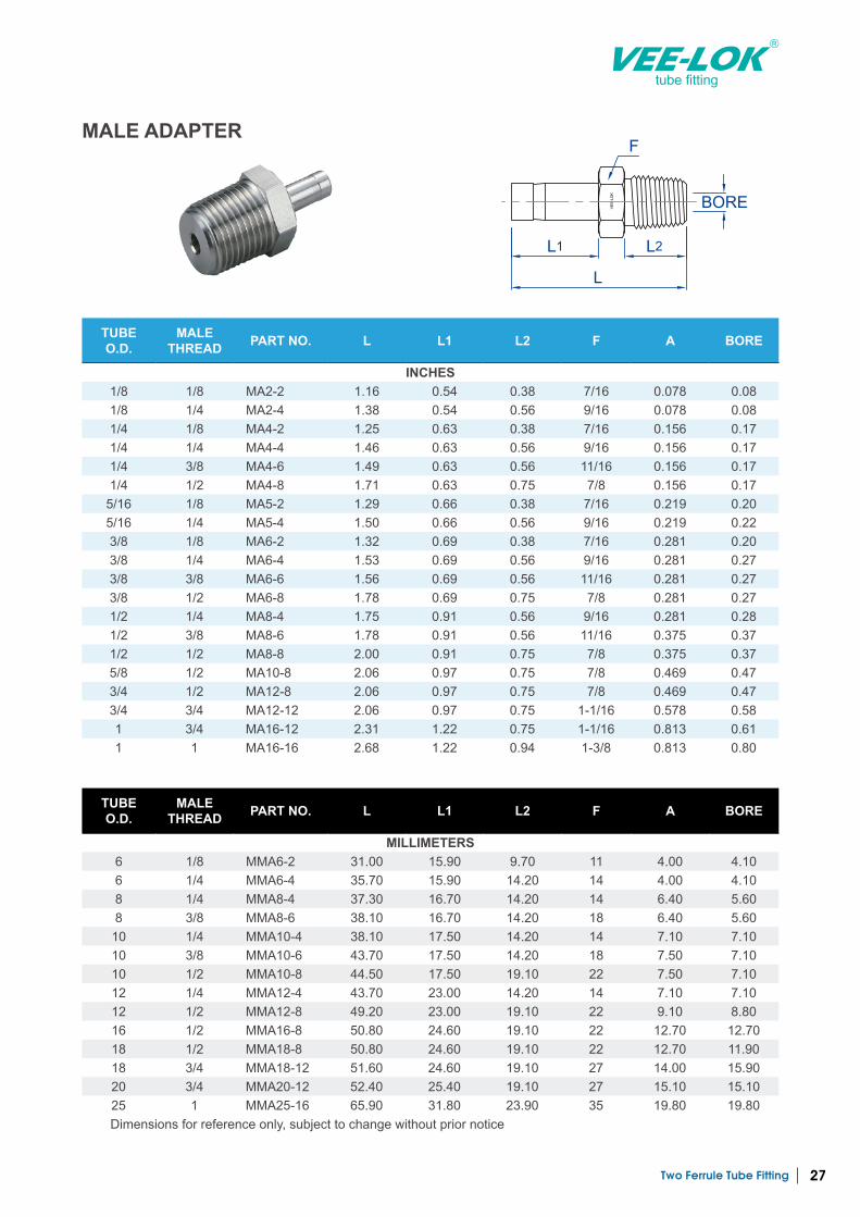
MALE ADAPTER
VE
E-L
OK
L1
L
L2
F
BORE
TUBE O.D.
MALE THREAD PART NO. L L1 L2 F A BORE
INCHES1/8 1/8 MA2-2 1.16 0.54 0.38 7/16 0.078 0.08 1/8 1/4 MA2-4 1.38 0.54 0.56 9/16 0.078 0.08 1/4 1/8 MA4-2 1.25 0.63 0.38 7/16 0.156 0.17 1/4 1/4 MA4-4 1.46 0.63 0.56 9/16 0.156 0.17 1/4 3/8 MA4-6 1.49 0.63 0.56 11/16 0.156 0.17 1/4 1/2 MA4-8 1.71 0.63 0.75 7/8 0.156 0.17
5/16 1/8 MA5-2 1.29 0.66 0.38 7/16 0.219 0.20 5/16 1/4 MA5-4 1.50 0.66 0.56 9/16 0.219 0.22 3/8 1/8 MA6-2 1.32 0.69 0.38 7/16 0.281 0.20 3/8 1/4 MA6-4 1.53 0.69 0.56 9/16 0.281 0.27 3/8 3/8 MA6-6 1.56 0.69 0.56 11/16 0.281 0.27 3/8 1/2 MA6-8 1.78 0.69 0.75 7/8 0.281 0.27 1/2 1/4 MA8-4 1.75 0.91 0.56 9/16 0.281 0.28 1/2 3/8 MA8-6 1.78 0.91 0.56 11/16 0.375 0.37 1/2 1/2 MA8-8 2.00 0.91 0.75 7/8 0.375 0.37 5/8 1/2 MA10-8 2.06 0.97 0.75 7/8 0.469 0.47 3/4 1/2 MA12-8 2.06 0.97 0.75 7/8 0.469 0.47 3/4 3/4 MA12-12 2.06 0.97 0.75 1-1/16 0.578 0.58 1 3/4 MA16-12 2.31 1.22 0.75 1-1/16 0.813 0.61 1 1 MA16-16 2.68 1.22 0.94 1-3/8 0.813 0.80
TUBE O.D.
MALE THREAD PART NO. L L1 L2 F A BORE
MILLIMETERS6 1/8 MMA6-2 31.00 15.90 9.70 11 4.00 4.10 6 1/4 MMA6-4 35.70 15.90 14.20 14 4.00 4.10 8 1/4 MMA8-4 37.30 16.70 14.20 14 6.40 5.60 8 3/8 MMA8-6 38.10 16.70 14.20 18 6.40 5.60
10 1/4 MMA10-4 38.10 17.50 14.20 14 7.10 7.10 10 3/8 MMA10-6 43.70 17.50 14.20 18 7.50 7.10 10 1/2 MMA10-8 44.50 17.50 19.10 22 7.50 7.10 12 1/4 MMA12-4 43.70 23.00 14.20 14 7.10 7.10 12 1/2 MMA12-8 49.20 23.00 19.10 22 9.10 8.80 16 1/2 MMA16-8 50.80 24.60 19.10 22 12.70 12.70 18 1/2 MMA18-8 50.80 24.60 19.10 22 12.70 11.90 18 3/4 MMA18-12 51.60 24.60 19.10 27 14.00 15.90 20 3/4 MMA20-12 52.40 25.40 19.10 27 15.10 15.10 25 1 MMA25-16 65.90 31.80 23.90 35 19.80 19.80 Dimensions for reference only, subject to change without prior notice
Two Ferrule Tube Fitting28
tube fitting
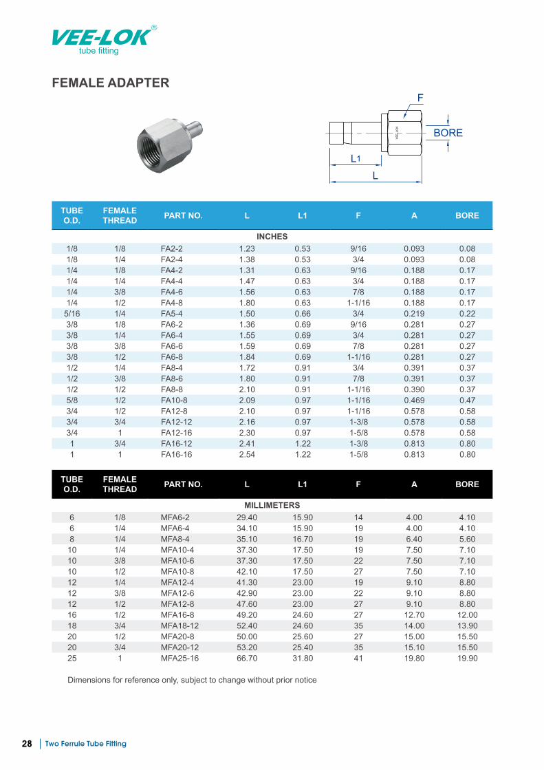
FEMALE ADAPTER
VE
E-L
OK
L1
L
F
BORE
TUBE O.D.
FEMALE THREAD PART NO. L L1 F A BORE
INCHES1/8 1/8 FA2-2 1.23 0.53 9/16 0.093 0.08 1/8 1/4 FA2-4 1.38 0.53 3/4 0.093 0.08 1/4 1/8 FA4-2 1.31 0.63 9/16 0.188 0.17 1/4 1/4 FA4-4 1.47 0.63 3/4 0.188 0.17 1/4 3/8 FA4-6 1.56 0.63 7/8 0.188 0.17 1/4 1/2 FA4-8 1.80 0.63 1-1/16 0.188 0.17 5/16 1/4 FA5-4 1.50 0.66 3/4 0.219 0.22 3/8 1/8 FA6-2 1.36 0.69 9/16 0.281 0.27 3/8 1/4 FA6-4 1.55 0.69 3/4 0.281 0.27 3/8 3/8 FA6-6 1.59 0.69 7/8 0.281 0.27 3/8 1/2 FA6-8 1.84 0.69 1-1/16 0.281 0.27 1/2 1/4 FA8-4 1.72 0.91 3/4 0.391 0.37 1/2 3/8 FA8-6 1.80 0.91 7/8 0.391 0.37 1/2 1/2 FA8-8 2.10 0.91 1-1/16 0.390 0.37 5/8 1/2 FA10-8 2.09 0.97 1-1/16 0.469 0.47 3/4 1/2 FA12-8 2.10 0.97 1-1/16 0.578 0.58 3/4 3/4 FA12-12 2.16 0.97 1-3/8 0.578 0.58 3/4 1 FA12-16 2.30 0.97 1-5/8 0.578 0.58 1 3/4 FA16-12 2.41 1.22 1-3/8 0.813 0.80 1 1 FA16-16 2.54 1.22 1-5/8 0.813 0.80
TUBE O.D.
FEMALE THREAD PART NO. L L1 F A BORE
MILLIMETERS6 1/8 MFA6-2 29.40 15.90 14 4.00 4.10 6 1/4 MFA6-4 34.10 15.90 19 4.00 4.10 8 1/4 MFA8-4 35.10 16.70 19 6.40 5.60 10 1/4 MFA10-4 37.30 17.50 19 7.50 7.10 10 3/8 MFA10-6 37.30 17.50 22 7.50 7.10 10 1/2 MFA10-8 42.10 17.50 27 7.50 7.10 12 1/4 MFA12-4 41.30 23.00 19 9.10 8.80 12 3/8 MFA12-6 42.90 23.00 22 9.10 8.80 12 1/2 MFA12-8 47.60 23.00 27 9.10 8.80 16 1/2 MFA16-8 49.20 24.60 27 12.70 12.00 18 3/4 MFA18-12 52.40 24.60 35 14.00 13.90 20 1/2 MFA20-8 50.00 25.60 27 15.00 15.50 20 3/4 MFA20-12 53.20 25.40 35 15.10 15.50 25 1 MFA25-16 66.70 31.80 41 19.80 19.90
Dimensions for reference only, subject to change without prior notice
L
F
Two Ferrule Tube Fitting 29
tube fitting
L
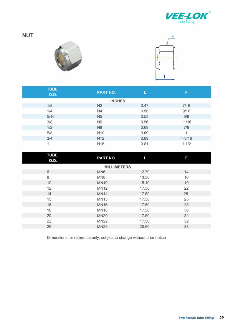
FNUT
Two Ferrule Tube Fitting30
tube fitting
BACK FERRULE
Two Ferrule Tube Fitting 31
tube fitting
FRONT FERRULE
Two Ferrule Tube Fitting32
tube fitting
PLUG CAP

www.veelok.com
Vertex Co., Ltd.3F, No.3, Lane 551, Sec. 1, Wanshou Rd.,Gueishan Township, Taoyuan County 33351,Taiwan Tel: +886 2 8200 3813Fax: +886 2 8200 [email protected]