new methods for monitoring neutral grounding...
TRANSCRIPT

New Methods for Monitoring Neutral Grounding Resistors
Rahim Jafari — Western UniversityMital Kanabar, Ilia Voloh — GE Grid Solutions
Tarlochan S. Sidhu — The University of Ontario Institute of Technology
Abstract — Electrical power systems control arcing current and electrical shock hazard by properneutral grounding such as high resistance grounding. The high resistance neutral grounding resis-tors fail due to vibration, intermittent arcs, corrosion, etc. and cause the risk of the system beingungrounded, or solidly grounded. In this paper, two efficient solutions are introduced that providecontinuous monitoring of such resistors installed at neutral of two most common configurations ofthe unit-connected generators. The first proposed method relies on the third harmonic of neutral andresidual voltages, and the second technique employs the sub-harmonic injection based generator statorground protection. The proposed methods show satisfying performance under different conditions ofthe resistor and generator, observed through comprehensive software analysis and further hardwarevalidations. The first proposed monitoring method has been retrofitted to an industrial generatorprotection relay which no longer maloperates due to failed-short neutral grounding resistor. Proposedtechniques can be incorporated into digital protective relays, which will monitor and alarm in caseof the failed grounding resistor.
Index Terms — Neutral Grounding Resistor, Unit-Connected Generator, Signal Injection.
I. INTRODUCTION
Neutral Grounding Resistors (NGR) protect power system generators and transformers by controllingthe ground overcurrent and transient overvoltages [1]. Integrity and intactness of these apparatusesare necessary to prevent the system from being ungrounded or solidly grounded [2], [3]. As such, theNGRs should be continuously monitored to avoid the false sense of safety, as mandated by CanadianElectric Code (CEC) and National Electric Code (NEC).
The various existing NGR monitoring methods are classified into three categories called passive,active, and passive-active methods. The passive methods utilize the inherent voltage and/or current ofthe grounding system. The active methods employ signal injection. Lastly, the passive-active methodscombine both the passive and active concepts, which results in a very comprehensive solution. Thereare six different passive approaches under the passive class that are briefly explained:
• Method P1 — Preventive maintenance is the traditional approach to inspect and ensure theintactness of the NGRs. This method is not known as continuous monitoring since it cannotprovide the online status of the NGR and is functional only during the planned inspection [3].
• Method P2 — The second passive approach relies on the negligible current that appears inneutral system due to inherent asymmetry of the power system. It supervises the presence of
this current and detects the disconnected NGR in the case of absence of the current [2]. Thistechnique cannot identify the partially failed NGR condition.
• Method P3 — The resistance of the NGR has been targeted by the third passive approach usingthe neutral voltage and current obtained by neutral PT and CT, respectively. This method is alsonot a continuous monitoring since the mentioned measurement instruments cannot measure thevery low voltage and current of the neutral system in normal operation condition of the powersystem where there is no ground fault [2].
• Method P4 — The fourth passive approach is, indeed, an enhanced version of the thirdtechnique since it uses the residual voltage, obtained by three-phase PTs that are wye-broken-delta connected, instead of neutral voltage. However, it faces the same limitations in the absenceof ground faults [4].
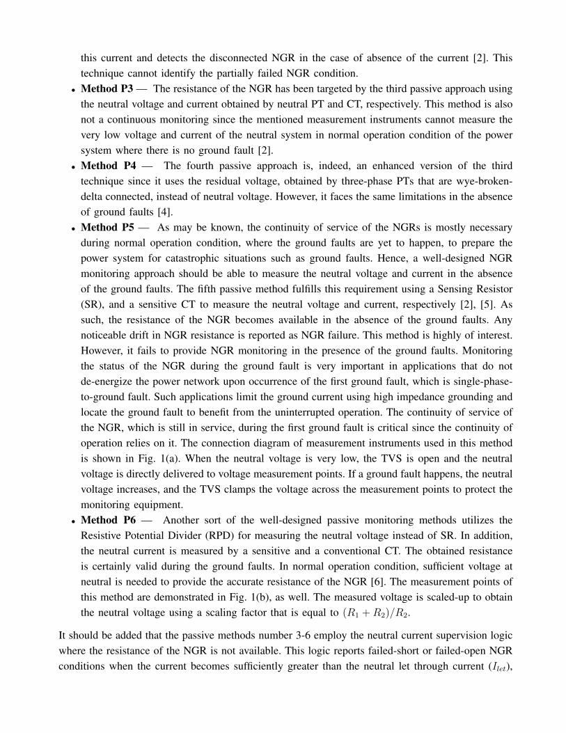
• Method P5 — As may be known, the continuity of service of the NGRs is mostly necessaryduring normal operation condition, where the ground faults are yet to happen, to prepare thepower system for catastrophic situations such as ground faults. Hence, a well-designed NGRmonitoring approach should be able to measure the neutral voltage and current in the absenceof the ground faults. The fifth passive method fulfills this requirement using a Sensing Resistor(SR), and a sensitive CT to measure the neutral voltage and current, respectively [2], [5]. Assuch, the resistance of the NGR becomes available in the absence of the ground faults. Anynoticeable drift in NGR resistance is reported as NGR failure. This method is highly of interest.However, it fails to provide NGR monitoring in the presence of the ground faults. Monitoringthe status of the NGR during the ground fault is very important in applications that do notde-energize the power network upon occurrence of the first ground fault, which is single-phase-to-ground fault. Such applications limit the ground current using high impedance grounding andlocate the ground fault to benefit from the uninterrupted operation. The continuity of service ofthe NGR, which is still in service, during the first ground fault is critical since the continuity ofoperation relies on it. The connection diagram of measurement instruments used in this methodis shown in Fig. 1(a). When the neutral voltage is very low, the TVS is open and the neutralvoltage is directly delivered to voltage measurement points. If a ground fault happens, the neutralvoltage increases, and the TVS clamps the voltage across the measurement points to protect themonitoring equipment.
• Method P6 — Another sort of the well-designed passive monitoring methods utilizes theResistive Potential Divider (RPD) for measuring the neutral voltage instead of SR. In addition,the neutral current is measured by a sensitive and a conventional CT. The obtained resistanceis certainly valid during the ground faults. In normal operation condition, sufficient voltage atneutral is needed to provide the accurate resistance of the NGR [6]. The measurement points ofthis method are demonstrated in Fig. 1(b), as well. The measured voltage is scaled-up to obtainthe neutral voltage using a scaling factor that is equal to (R1 + R2)/R2.
It should be added that the passive methods number 3-6 employ the neutral current supervision logicwhere the resistance of the NGR is not available. This logic reports failed-short or failed-open NGRconditions when the current becomes sufficiently greater than the neutral let through current (Ilet),
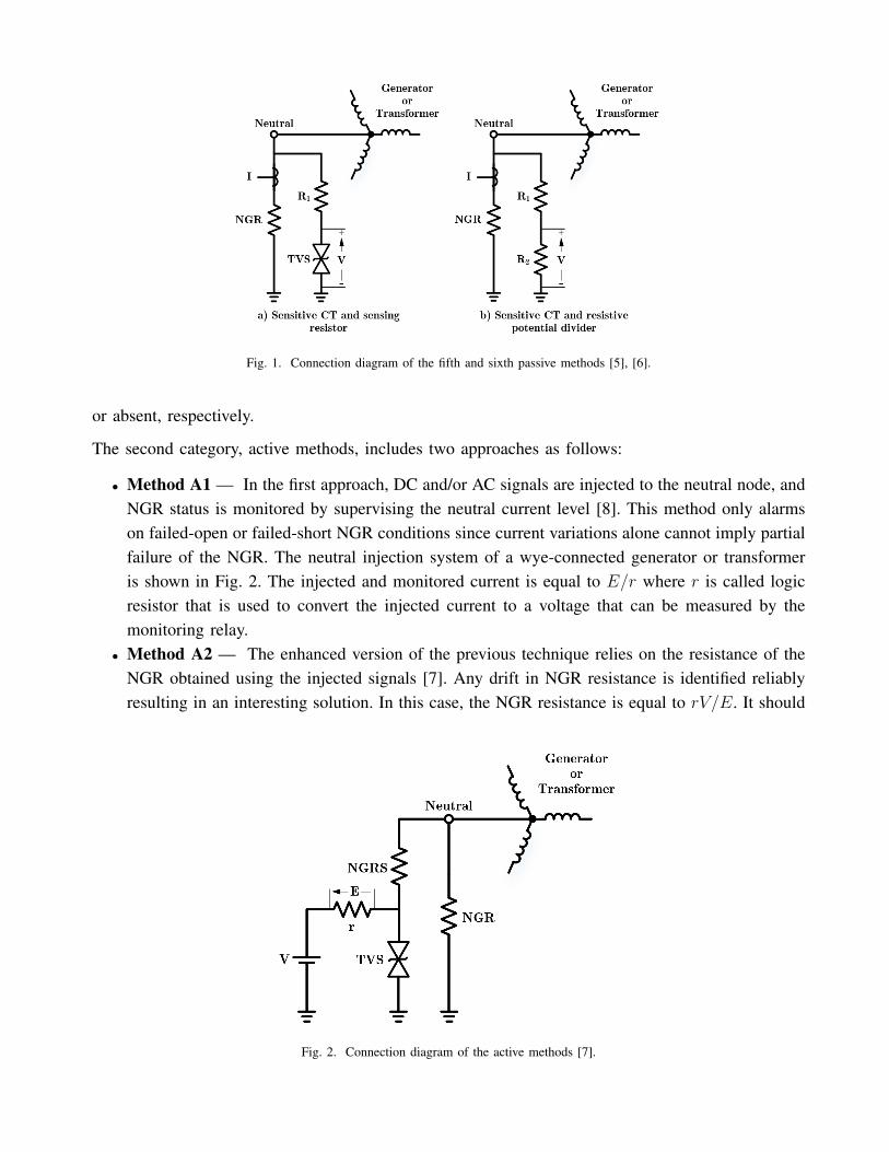
Fig. 1. Connection diagram of the fifth and sixth passive methods [5], [6].
or absent, respectively.
The second category, active methods, includes two approaches as follows:
• Method A1 — In the first approach, DC and/or AC signals are injected to the neutral node, andNGR status is monitored by supervising the neutral current level [8]. This method only alarmson failed-open or failed-short NGR conditions since current variations alone cannot imply partialfailure of the NGR. The neutral injection system of a wye-connected generator or transformeris shown in Fig. 2. The injected and monitored current is equal to E/r where r is called logicresistor that is used to convert the injected current to a voltage that can be measured by themonitoring relay.
• Method A2 — The enhanced version of the previous technique relies on the resistance of theNGR obtained using the injected signals [7]. Any drift in NGR resistance is identified reliablyresulting in an interesting solution. In this case, the NGR resistance is equal to rV/E. It should
Fig. 2. Connection diagram of the active methods [7].

be noted that if multiple AC and DC signals are injected, the resistance at different frequenciesbecomes available that support different applications such as monitoring the NGR continuityduring the start-up procedure or de-energized condition.
The issues associated with the active methods are: 1) they cannot monitor in the presence of theground faults since the protection means of the injection system decouple the monitoring relay fromthe neutral node for safety issues, and 2) the injection circuit can fail itself resulting in malfunctionand complexity, i.e., the need for monitoring the monitor.
As elaborated, the active methods operate reliable in the absence of the ground faults while thepassive methods function properly in the presence of the ground faults. Therefore, any feasiblecombination of the passive and active methods, hereafter called passive-active methods, will resultin the best performance. For example, the combination of the sixth passive method with the secondactive method results in a monitor that operates reliably in both normal and faulted conditions. Thiscategory of NGR monitoring methods are expected to emerge in near future.
The existing and anticipated NGR monitoring methods are represented in Fig. 3. This figure showsthe evolution of the art of NGR monitoring, as well.
Fig. 3. Existing NGR monitoring methods and concepts.
In this paper, the NGR at neutral of unit-connected generators is monitored using both passive andpassive-active methods depending on the configuration. The proposed passive method, which relieson the third harmonic of the neutral and residual voltages of the generator, is used for generators thatlack the signal injection based generator stator ground protection. However, a passive-active methodwill be used for the generator equipped with the mentioned injection system.
II. PROPOSED MONITORING TECHNIQUE FOR CONFIGURATION 1
A. Fundamentals of the proposed technique
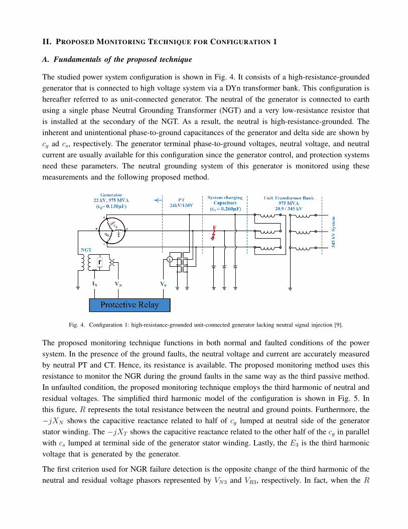
The studied power system configuration is shown in Fig. 4. It consists of a high-resistance-groundedgenerator that is connected to high voltage system via a DYn transformer bank. This configuration ishereafter referred to as unit-connected generator. The neutral of the generator is connected to earthusing a single phase Neutral Grounding Transformer (NGT) and a very low-resistance resistor thatis installed at the secondary of the NGT. As a result, the neutral is high-resistance-grounded. Theinherent and unintentional phase-to-ground capacitances of the generator and delta side are shown bycg ad cs, respectively. The generator terminal phase-to-ground voltages, neutral voltage, and neutralcurrent are usually available for this configuration since the generator control, and protection systemsneed these parameters. The neutral grounding system of this generator is monitored using thesemeasurements and the following proposed method.
Fig. 4. Configuration 1: high-resistance-grounded unit-connected generator lacking neutral signal injection [9].
The proposed monitoring technique functions in both normal and faulted conditions of the powersystem. In the presence of the ground faults, the neutral voltage and current are accurately measuredby neutral PT and CT. Hence, its resistance is available. The proposed monitoring method uses thisresistance to monitor the NGR during the ground faults in the same way as the third passive method.In unfaulted condition, the proposed monitoring technique employs the third harmonic of neutral andresidual voltages. The simplified third harmonic model of the configuration is shown in Fig. 5. Inthis figure, R represents the total resistance between the neutral and ground points. Furthermore, the−jXN shows the capacitive reactance related to half of cg lumped at neutral side of the generatorstator winding. The −jXT shows the capacitive reactance related to the other half of the cg in parallelwith cs lumped at terminal side of the generator stator winding. Lastly, the E3 is the third harmonicvoltage that is generated by the generator.
The first criterion used for NGR failure detection is the opposite change of the third harmonic of theneutral and residual voltage phasors represented by VN3 and VR3, respectively. In fact, when the R
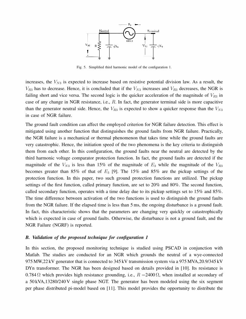
Fig. 5. Simplified third harmonic model of the configuration 1.
increases, the VN3 is expected to increase based on resistive potential division law. As a result, theVR3 has to decrease. Hence, it is concluded that if the VN3 increases and VR3 decreases, the NGR isfailing short and vice versa. The second logic is the quicker acceleration of the magnitude of VR3 incase of any change in NGR resistance, i.e., R. In fact, the generator terminal side is more capacitivethan the generator neutral side. Hence, the VR3 is expected to show a quicker response than the VN3
in case of NGR failure.
The ground fault condition can affect the employed criterion for NGR failure detection. This effect ismitigated using another function that distinguishes the ground faults from NGR failure. Practically,the NGR failure is a mechanical or thermal phenomenon that takes time while the ground faults arevery catastrophic. Hence, the initiation speed of the two phenomena is the key criteria to distinguishthem from each other. In this configuration, the ground faults near the neutral are detected by thethird harmonic voltage comparator protection function. In fact, the ground faults are detected if themagnitude of the VN3 is less than 15% of the magnitude of E3 while the magnitude of the VR3
becomes greater than 85% of that of E3 [9]. The 15% and 85% are the pickup settings of theprotection function. In this paper, two such ground protection functions are utilized. The pickupsettings of the first function, called primary function, are set to 20% and 80%. The second function,called secondary function, operates with a time delay due to its pickup settings set to 15% and 85%.The time difference between activation of the two functions is used to distinguish the ground faultsfrom the NGR failure. If the elapsed time is less than 5 ms, the ongoing disturbance is a ground fault.In fact, this characteristic shows that the parameters are changing very quickly or catastrophicallywhich is expected in case of ground faults. Otherwise, the disturbance is not a ground fault, and theNGR Failure (NGRF) is reported.
B. Validation of the proposed technique for configuration 1
In this section, the proposed monitoring technique is studied using PSCAD in conjunction withMatlab. The studies are conducted for an NGR which grounds the neutral of a wye-connected975 MW,22 kV generator that is connected to 345 kV transmission system via a 975 MVA,20.9/345 kVDYn transformer. The NGR has been designed based on details provided in [10]. Its resistance is0.784 Ω which provides high resistance grounding, i.e., R =2400 Ω, when installed at secondary ofa 50 kVA,13280/240 V single phase NGT. The generator has been modeled using the six segmentper phase distributed pi-model based on [11]. This model provides the opportunity to distribute the
generator phase-to-ground capacitances along the winding and also simulating the internal groundfaults.
The performance of the proposed passive technique for monitoring the NGR has been investigatedfor various kinds of NGR degradations considering different modes of operation of the power system.Observations show that it functions reliably detecting the precise status of the NGR. Additionally,the ground faults are well-distinguished from failed-short NGR condition.
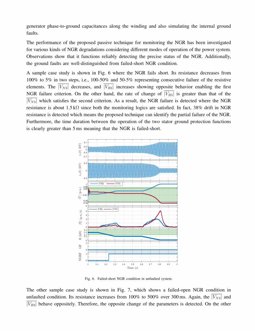
A sample case study is shown in Fig. 6 where the NGR fails short. Its resistance decreases from100% to 5% in two steps, i.e., 100-50% and 50-5% representing consecutive failure of the resistiveelements. The |VN3| decreases, and |VR3| increases showing opposite behavior enabling the firstNGR failure criterion. On the other hand, the rate of change of |VR3| is greater than that of the|VN3| which satisfies the second criterion. As a result, the NGR failure is detected where the NGRresistance is about 1.5 kΩ since both the monitoring logics are satisfied. In fact, 38% drift in NGRresistance is detected which means the proposed technique can identify the partial failure of the NGR.Furthermore, the time duration between the operation of the two stator ground protection functionsis clearly greater than 5 ms meaning that the NGR is failed-short.
-0.7
-0.30
0.3
0.7
-0.3
0
0.3
0
0.50
1
0
1
2
3
4
0
1.21.72.43.1
0
1
1 1.1 1.2 1.3 1.4 1.5 1.6 1.7 1.8 1.9 2
0
1
0.850.80
0.150.20
Fig. 6. Failed-short NGR condition in unfaulted system.
The other sample case study is shown in Fig. 7, which shows a failed-open NGR condition inunfaulted condition. Its resistance increases from 100% to 500% over 300 ms. Again, the |VN3| and|VR3| behave oppositely. Therefore, the opposite change of the parameters is detected. On the other

hand, the rate of change of |VR3| is greater than that of the |VN3| which satisfies the second logic.As a result, the NGR failure is detected where the NGR resistance is about 5.5 kΩ since both themonitoring logics are satisfied. As shown, none of the |VN3| and |VR3| pass through the thresholds ofthe ground protection functions. As such, the other logic of NGR failure detection is not activated.However, the quicker behavior of the |VR3| than the |VN3| helped identifying the NGR failure whichhas been reported 100 ms after that the resistance of the NGR drifts outside the safe region.
-0.30
-0.15
0
0.15
0.30
-0.30
-0.15
0
0.15
0.30
0
0.50
1
0
0.2
0.4
0.6
0.8
1
02.4
57.510
12.5
0
1
1 1.1 1.2 1.3 1.4 1.5 1.6 1.7 1.8 1.9 2
0
1
0.20
0.800.85
0.15
Fig. 7. Failed-open NGR condition in unfaulted system.
As observed, this technique does not use the resistance of the NGR for monitoring; but, it comparesthe neutral and residual voltages to detect NGR degradation. The studies show that the ±20% changein the resistance of the intact NGR is detected. It should be mentioned that the very slowly failingNGR condition is not detected unless the NGR becomes entirely shorted, which is detected by theelapsed time between activations of the thresholds of the two generator stator ground protectionfunctions.
Distinguishing the ground faults from the failed-short NGR condition is demonstrated using an indus-trial generator protection relay, as shown in Fig. 8. The NGR failure and ground faults are simulatedin PSCAD, and the waveforms are captured using COMTRADE 91. Thereafter, the waveformsare played back to the relay using LabVIEW and National Instrument cDAQ-9178. The preparedexperiment is a low voltage injection hardware test setup since the PTs and CTs of the utilizedrelay are bypassed to be able to focus only on the proposed algorithm and avoid involving the high
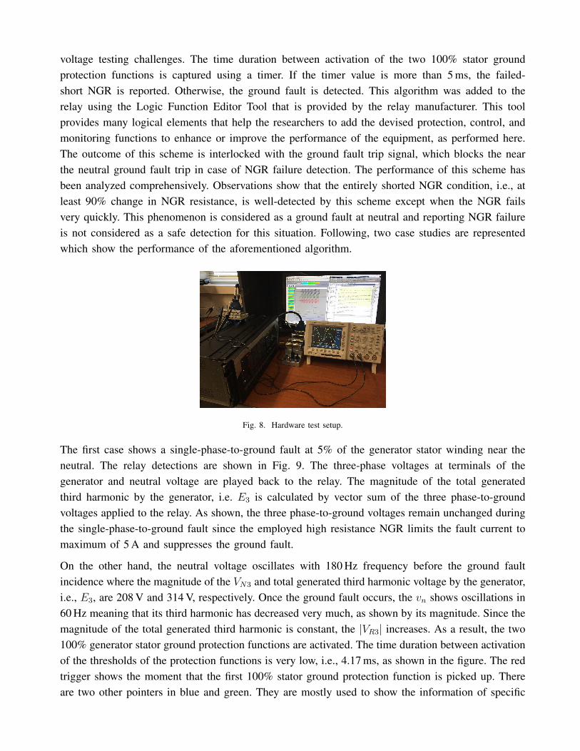
voltage testing challenges. The time duration between activation of the two 100% stator groundprotection functions is captured using a timer. If the timer value is more than 5 ms, the failed-short NGR is reported. Otherwise, the ground fault is detected. This algorithm was added to therelay using the Logic Function Editor Tool that is provided by the relay manufacturer. This toolprovides many logical elements that help the researchers to add the devised protection, control, andmonitoring functions to enhance or improve the performance of the equipment, as performed here.The outcome of this scheme is interlocked with the ground fault trip signal, which blocks the nearthe neutral ground fault trip in case of NGR failure detection. The performance of this scheme hasbeen analyzed comprehensively. Observations show that the entirely shorted NGR condition, i.e., atleast 90% change in NGR resistance, is well-detected by this scheme except when the NGR failsvery quickly. This phenomenon is considered as a ground fault at neutral and reporting NGR failureis not considered as a safe detection for this situation. Following, two case studies are representedwhich show the performance of the aforementioned algorithm.
Fig. 8. Hardware test setup.
The first case shows a single-phase-to-ground fault at 5% of the generator stator winding near theneutral. The relay detections are shown in Fig. 9. The three-phase voltages at terminals of thegenerator and neutral voltage are played back to the relay. The magnitude of the total generatedthird harmonic by the generator, i.e. E3 is calculated by vector sum of the three phase-to-groundvoltages applied to the relay. As shown, the three phase-to-ground voltages remain unchanged duringthe single-phase-to-ground fault since the employed high resistance NGR limits the fault current tomaximum of 5 A and suppresses the ground fault.
On the other hand, the neutral voltage oscillates with 180 Hz frequency before the ground faultincidence where the magnitude of the VN3 and total generated third harmonic voltage by the generator,i.e., E3, are 208 V and 314 V, respectively. Once the ground fault occurs, the vn shows oscillations in60 Hz meaning that its third harmonic has decreased very much, as shown by its magnitude. Since themagnitude of the total generated third harmonic is constant, the |VR3| increases. As a result, the two100% generator stator ground protection functions are activated. The time duration between activationof the thresholds of the protection functions is very low, i.e., 4.17 ms, as shown in the figure. The redtrigger shows the moment that the first 100% stator ground protection function is picked up. Thereare two other pointers in blue and green. They are mostly used to show the information of specific
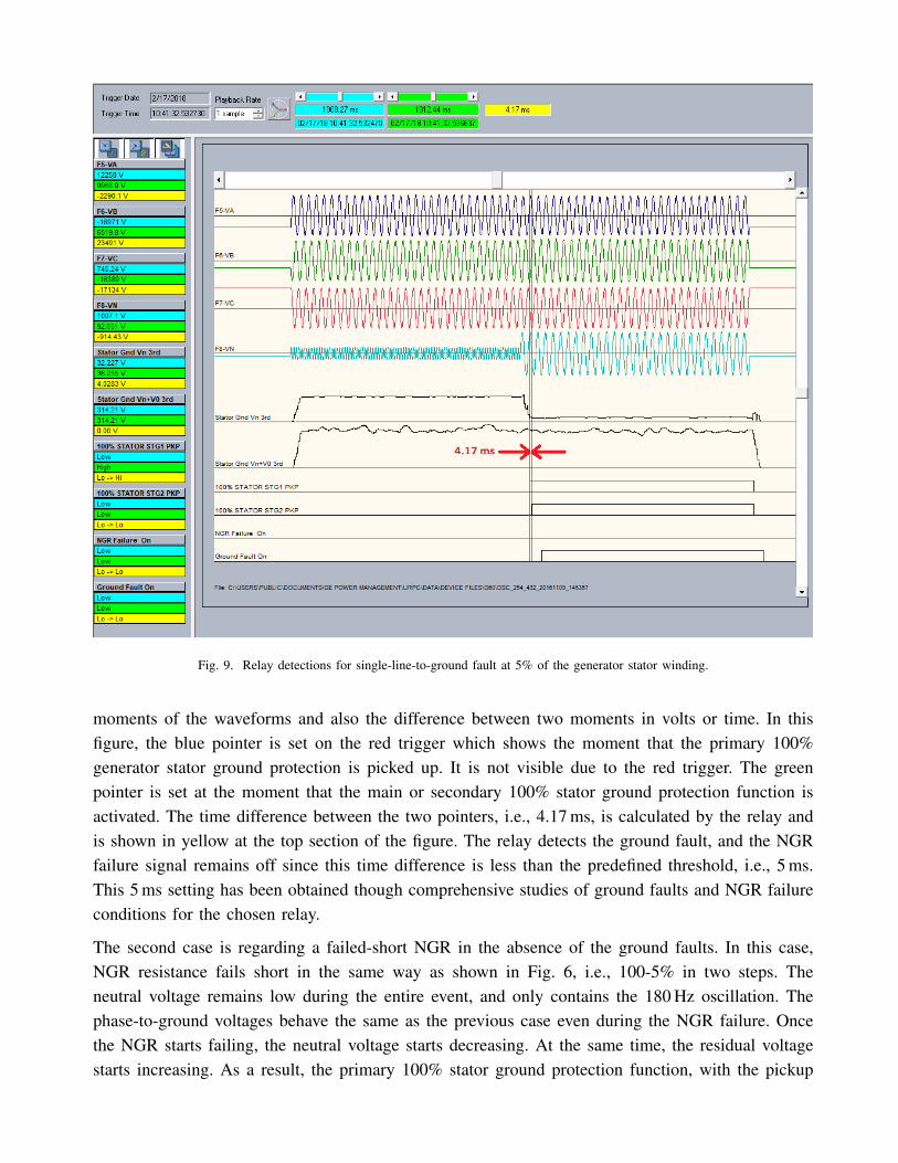
Fig. 9. Relay detections for single-line-to-ground fault at 5% of the generator stator winding.
moments of the waveforms and also the difference between two moments in volts or time. In thisfigure, the blue pointer is set on the red trigger which shows the moment that the primary 100%generator stator ground protection is picked up. It is not visible due to the red trigger. The greenpointer is set at the moment that the main or secondary 100% stator ground protection function isactivated. The time difference between the two pointers, i.e., 4.17 ms, is calculated by the relay andis shown in yellow at the top section of the figure. The relay detects the ground fault, and the NGRfailure signal remains off since this time difference is less than the predefined threshold, i.e., 5 ms.This 5 ms setting has been obtained though comprehensive studies of ground faults and NGR failureconditions for the chosen relay.
The second case is regarding a failed-short NGR in the absence of the ground faults. In this case,NGR resistance fails short in the same way as shown in Fig. 6, i.e., 100-5% in two steps. Theneutral voltage remains low during the entire event, and only contains the 180 Hz oscillation. Thephase-to-ground voltages behave the same as the previous case even during the NGR failure. Oncethe NGR starts failing, the neutral voltage starts decreasing. At the same time, the residual voltagestarts increasing. As a result, the primary 100% stator ground protection function, with the pickup

settings set to 20% and 80%, is activated. After a time delay, the secondary 100% stator groundprotection function, with the thresholds set to 15% and 85%, becomes enabled, as well. The timedelay between operation of the two protection functions is 9.9 ms. The monitoring scheme reportsNGR failure since this time difference is higher than 5 ms. Additionally, the ground fault trip signalremains off.
Fig. 10. Relay detections for failed-short NGR in unfaulted condition.
It should be mentioned that the proposed technique faces a few challenges. The first issue is thedisappearance of the employed parameters. In some specific applications, the generators might notgenerate sufficient third harmonic voltage, which makes the proposed method non-functional. Thatis why the signal injection based protection and monitoring of the neutral system of the generatorsare emerging these days. The other issue is the duration of the failure of the NGR. This kind ofdegradation is detected if 1) the |VN3| and |VR3| vary oppositely and 2) the rate of change of |VR3|is greater than that of the |VN3|. On the basis of the performed analysis, the very slow variation ofthe NGR resistance is not detected by this technique since the rate of change of the parameters areso low that cannot be detected.

III. PROPOSED MONITORING TECHNIQUE FOR CONFIGURATION 2
These days, many generator protection systems employ signal injection to detect the ground faultsnear the neutral of the generator stator winding, as shown in Fig. 11 [12]–[14]. This figure showsthe same configuration studied in the previous section except that it is equipped with 20 Hz injectionmeans. The generator phase-to-ground impedance seen from the neutral, i.e., Vinj/IN , is obtainedusing the injected signal. The ground faults are detected if the real part of the calculated impedancebecomes less than a predefined threshold. This parameter is usually very high, i.e., in the order of100 kΩ, and decreases to less than 1 kΩ in case of a ground fault in generator stator winding.
Fig. 11. Configuration 2: high-resistance-grounded unit-connected generator equipped with 20 Hz signal injection.
A. Fundamentals of the proposed technique
The signal injection means employed by the above-mentioned protective mechanism can be used forimplementing the active NGR monitoring methods. An additional current sensor for measuring theinjected current is needed to obtain the current that flows through the NGR. In fact, the NGR currentis obtained by subtraction of the NGT secondary current from the injected current at the injectionfrequency. Since the NGR voltage is also measured by the relay, its resistance is available at theinjected frequency. It should be noted that the injected signal cannot be extracted from the 60 Hzvoltage during the ground faults since the level of the 60 Hz voltage is very higher than that of theinjected voltage. Under this situation, the resistance of the NGR is obtained using the 60 Hz voltageand current that are measured by the line PTs and neutral CT.
B. Validation of the proposed technique for configuration 2
Along with comprehensive studies performed for investigating the performance of the proposedtechnique, two sample cases are explained in detail. The first sample case study is shown in Fig. 12. Inthis event, the NGR fails short from 100% to 5% in two steps, i.e., 100-50% and 50-5% representingtwo consecutively failing resistive elements of the NGR. As a result, the injected current increases.The voltage across the NGR and the portion of the injected current that penetrates to the high voltage
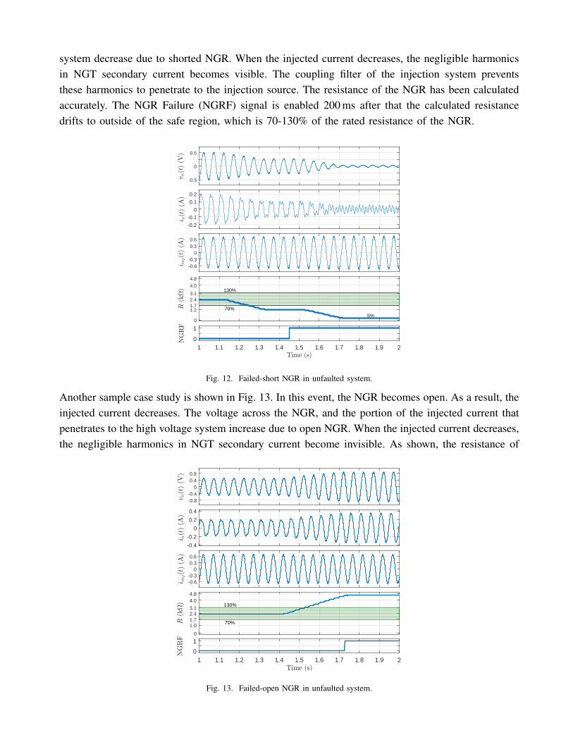
system decrease due to shorted NGR. When the injected current decreases, the negligible harmonicsin NGT secondary current becomes visible. The coupling filter of the injection system preventsthese harmonics to penetrate to the injection source. The resistance of the NGR has been calculatedaccurately. The NGR Failure (NGRF) signal is enabled 200 ms after that the calculated resistancedrifts to outside of the safe region, which is 70-130% of the rated resistance of the NGR.
-0.5
0
0.5
-0.2
-0.1
0
0.1
0.2
-0.6-0.3
00.30.6
0
1.21.72.43.1
4.04.8
70%
130%
1 1.1 1.2 1.3 1.4 1.5 1.6 1.7 1.8 1.9 20
1
5%
Fig. 12. Failed-short NGR in unfaulted system.
Another sample case study is shown in Fig. 13. In this event, the NGR becomes open. As a result, theinjected current decreases. The voltage across the NGR, and the portion of the injected current thatpenetrates to the high voltage system increase due to open NGR. When the injected current decreases,the negligible harmonics in NGT secondary current become invisible. As shown, the resistance of
-0.8-0.4
00.40.8
-0.4
-0.2
0
0.2
0.4
-0.6-0.3
00.30.6
0
1.01.72.43.1
4.04.8
70%
130%
1 1.1 1.2 1.3 1.4 1.5 1.6 1.7 1.8 1.9 20
1
Fig. 13. Failed-open NGR in unfaulted system.
the NGR has been calculated accurately. The NGR Failure (NGRF) signal is enabled 200 ms afterthat the calculated resistance drifts to outside of the green area, which is greater than 130% of therated resistance of the NGR.
It should be added that many other scenarios have been investigated to assess the performance of thistechnique. The observations show reliable operation of the proposed method even during the groundfaults, where the fundamental harmonic of the residual voltage and neutral current are employed.
IV. CONCLUSION
Two new techniques were proposed that monitor the integrity of the neutral grounding resistor of thehigh-resistance-grounded unit-connected generators.
The first proposed technique detects the failure of the resistor using the third harmonic of the neutraland residual voltages. Furthermore, the monitoring is performed based on the calculated resistanceof the resistor in the presence of the ground faults. This scheme shows reliable performance in bothnormal and faulted conditions.
The second proposed technique monitors the neutral grounding resistor using the existing injectioninfrastructures of the sub-harmonic injection based generator stator ground protection. This techniqueshows reliable operation as well. The integrity of the neutral grounding system during the groundfaults is monitored using the neutral-to-ground resistance.
The second proposed technique is more of interest since it provides monitoring in de-energizedsystems as well. In fact, the third harmonic voltages used in the first technique might disappear orbecome very weak even in energized system condition. However, the commissioning costs of thesecond technique are much more than the first method unless they exist already.
REFERENCES
[1] “IEEE Recommended Practice for Grounding of Industrial and Commercial Power Systems (IEEE Green Book),” ANSI/IEEEStd 142-1982, pp. 1–135, Sept 1982.
[2] D. Selkirk, M. Savostianik, and K. Crawford, “Why Neutral Grounding Resistors Need Continuous Monitoring,” in Petroleumand Chemical Industry Technical Conference, 2008. PCIC 2008. 55th IEEE, pp. 1–7, Sept 2008.
[3] D. Selkirk, M. Savostianik, and K. Crawford, “The Dangers of Grounding Resistor Failure,” IEEE Industry Applications Magazine,vol. 16, pp. 53–58, Sept 2010.
[4] Z. Toros, P. Kastelic, T. Kastelic, and S. Maljavac, “Neutral grounding resistor failure detection,” in 21st International Conferenceon Electricity Distribution Frankfurt,, June 2011.
[5] G. E. Paulson, “Monitoring Neutral Grounding Resistors,” in Pulp and Paper, 1999. Industry Technical Conference Record of1999 Annual, pp. 238–241, June 1999.
[6] J. Campbell and S. Panetta, “Ground fault circuit having circuit failure sensor, and method,” U.S. Patent 6,552,885, April, 22,2003.
[7] M. Vangool and G. Baker, “Neutral grounding resistor monitor,” Feb. 19 2015. US Patent App. 14/386,108.[8] D. Curtis, “Multi-frequency ground monitor current sensing,” U.S. Patent App. 14/473,568, March, 2, 2015.[9] “IEEE Guide for Generator Ground Protection,” IEEE Std C37.101-2006 (Revision of IEEE Std C37.101-1993/Incorporates IEEE
Std C37.101-2006/Cor1:2007), pp. 1–70, Nov 2007.[10] “IEEE Guide for the Application of Neutral Grounding in Electrical Utility Systems, Part II - Grounding of Synchronous
Generator Systems,” IEEE Std C62.92.2-1989, pp. 1–24, Sept 1989.
[11] R. L. Schlake, G. W. Buckley, and G. McPherson, “Performance of third harmonic ground fault protection schemes for generatorstator windings,” IEEE Transactions on Power Apparatus and Systems, vol. PAS-100, pp. 3195–3202, July 1981.
[12] N. Tai, X. Yin, Z. Zhang, and D. Chen, “Research of subharmonic injection schemes for hydro-generator stator ground protection,”in Power Engineering Society Winter Meeting, 2000. IEEE, vol. 3, pp. 1928–1932 vol.3, Jan 2000.
[13] S. Turner, “Applying 100% stator ground fault protection by low frequency injection for generators,” in Power Energy SocietyGeneral Meeting, 2009. PES ’09. IEEE, pp. 1–6, July 2009.
[14] M. Kanabar, O. Lapeyra, J. Momic, P. Kreidi, M. Das, and D. Nagalingam, “Experience with applying injection based 100%stator ground and rotor ground generator protections,,” in 41st Annual Western Protective Relay Conference, Oct 2014.
Rahim Jafari received his B.Sc. (Hons.) degree in electrical engineering in 2010 from TabrizUniversity, Iran and the M.Sc. in 2013 from the Center of Excellence on Electrical Power Systems,Amirkabir University of Technology (Tehran Polytechnic), Tehran, Iran. He is currently a Ph.D.researcher at The University of Western Ontario, London, Ontario, Canada. His research interestsinclude power system protection and monitoring, smart grids, and micro-grids. The main focus ofhis studies is developing new protection and monitoring concepts and techniques.
Mital Kanabar received his B.E. degree from Sardar Patel University India in 2003, and obtained hisM.Tech. degree from the Indian Institute of Technology (IIT) Bombay, India in 2007. He completedhis Ph.D. at the University of Western Ontario, London, Canada in 2011, and joined GE GridSolutions, Markham in May 2011. Mital is the author of a book chapter and magazine articles,as well as several journal papers and 15 conference papers. His areas of interest are synchrophasordata concentrator, wide area applications, IEC 61850 process bus, and generator protection.
Tarlochan S. Sidhu received his Ph.D. degree in electrical engineering from the University ofSaskatchewan, Saskatchewan, Saskatoon, SK, Canada, in 1989. He is currently a Professor and Deanof Faculty of Engineering and Applied Science at the University of Ontario Institute of Technology(UOIT), Oshawa, ON, Canada. Prior to this, he was a Professor and Chair of the Electrical andComputer Engineering Department at the University of Western Ontario, London, ON, Canada. Healso has held the NSERC/Hydro One Senior Industrial Research Chair in Power Systems Engineering.His research interests include power system protection, monitoring, control and automation.
Ilia Voloh received his Electrical Engineering degree from Ivanovo State Power University, Russia.He is currently an applications engineering manager with GE Grid Solutions, Canada. His areasof interest are advanced power system protection algorithms and advanced communications forprotective relaying. Ilia authored and co-authored more than 40 papers presented at major NorthAmerica Protective Relaying conferences. He is a member of IEC TC95 committee, active memberof the main IEEE PSRC committee and a senior member of the IEEE.