technical specification for neutral grounding resistor · 2014-12-15 · technical specification...
TRANSCRIPT
RAJASTHAN RAJYA VIDYUT UTPADAN NIGAM LTD.
2 X 660 MW SURATGARH STPS, STAGE-V, UNIT # 7&8
VOLUME – II
TECHNICAL SPECIFICATION FOR
NEUTRAL GROUNDING RESISTOR
BHEL DOCUMENT NO. : PE-TS-392-506-E002, REV-0
BHARAT HEAVY ELECTRICALS LIMITED POWER SECTOR
PROJECT ENGINEERING MANAGEMENT NOIDA – 201301
TECHNICAL SPECIFICATION FOR NEUTRAL GROUNDING
RESISTOR 2X660 MW SURATGARH STPS, UNIT
#7&8
SPECIFICATION NO. PE-TS- 392-506-E003
VOLUME II B
SECTION ---
REVISION 0 DATE: 01.12.14
SHEET 1 OF 1
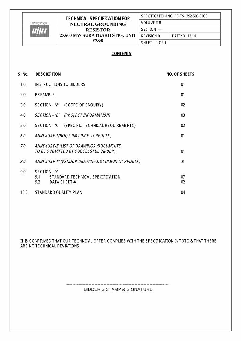
CONTENTS
S. No. DESCRIPTION NO. OF SHEETS
1.0 INSTRUCTIONS TO BIDDERS 01 2.0 PREAMBLE 01 3.0 SECTION – ‘A’ (SCOPE OF ENQUIRY) 02 4.0 SECTION – ‘B’ (PROJECT INFORMATION) 03 5.0 SECTION – ‘C’ (SPECIFIC TECHNICAL REQUIREMENTS) 02
6.0 ANNEXURE-I (BOQ CUM PRICE SCHEDULE) 01 7.0 ANNEXURE-II (LIST OF DRAWINGS /DOCUMENTS
TO BE SUBMITTED BY SUCCESSFUL BIDDER) 01
8.0 ANNEXURE-III (VENDOR DRAWING/DOCUMENT SCHEDULE) 01 9.0 SECTION- ‘D’
9.1 STANDARD TECHNICAL SPECIFICATION 07 9.2 DATA SHEET-A 02
10.0 STANDARD QUALITY PLAN 04 IT IS CONFIRMED THAT OUR TECHNICAL OFFER COMPLIES WITH THE SPECIFICATION IN TOTO & THAT THERE ARE NO TECHNICAL DEVIATIONS. ---------------------------------------------------------------------
BIDDER’S STAMP & SIGNATURE

TECHNICAL SPECIFICATION FOR NEUTRAL GROUNDING
RESISTOR 2X660 MW SURATGARH STPS,
UNIT #7&8
SPECIFICATION NO. PE-TS-392-506-E003
VOLUME II B
SECTION ---
REVISION 0 DATE: 01.12.14
SHEET 1 OF 1
INSTRUCTIONS TO BIDDERS FOR PREPARING TECHNICAL OFFER
1. Two signed and stamped copies of the following shall be furnished by all bidders as technical offer :
a. Unpriced Price Schedule (Annexure-I: BOQ CUM PRICE SCHEDULE, as enclosed with the
specification). b. A copy of this sheet (“Instructions to Bidders for Preparing Technical Offer”). c. A copy of previous sheet (“Contents”).
2. No other technical submittal such as copies of type test certificates, data sheets, write-up, drawing, technical
literature, etc. is required during tender stage. Any such submission, even if made, shall not be considered as part of offer.
3. No comments/ additions/ deletions shall be made by the bidder on the signed & stamped copy of the specification.
Any such changes made by the bidder shall not be considered.
4. Confirmations/ comments (if any) regarding delivery schedules shall be furnished as part of the commercial offer. Any reference in the technical offer / covering letter shall not be considered by BHEL.
5. Any comments/ clarifications on technical/ inspection requirements furnished as part of bidder’s covering letter shall
not be considered by BHEL, and bidder’s offer shall be construed to be in conformance with the specification.
6. Any changes made by the bidder in the price schedule with respect to the item description/ quantities, notes etc. from those given in Annexure-I of specification [Bill Of Quantities] shall not be considered (i.e., technical description, quantities, notes etc. as per specification shall prevail).
--------------------------------------------------------------------- BIDDER’S STAMP & SIGNATURE

TECHNICAL SPECIFICATION FOR NEUTRAL GROUNDING
RESISTOR 2X660 MW SURATGARH STPS, UNIT
#7&8
SPECIFICATION NO. PE-TS-392-506-E003
VOLUME II B
SECTION ---
REVISION 0 DATE: 01.12.14
SHEET 1 OF 1
PREAMBLE
1.0 The tender document contains two (2) volumes. The bidder shall meet the requirements of all the two volumes. 1.1 Volume-I (CONDITIONS OF CONTRACT) This consists of four parts as below:-
Volume-IA : This part contains instructions to bidders for making bids to BHEL.
Volume-IB : This part contains General Commercial Conditions of the tender & includes provision
that vendor is responsible for the quality of item supplied by their sub-vendors.
Volume-IC : This part contains special conditions of contract.
Volume-ID : This part contains commercial conditions for erection & commissioning site work,
as applicable.
1.2 Volume-II (TECHNICAL SPECIFICATION) Technical requirements are stipulated in Volume-II which comprises of :-
Volume-IIA : General Technical Conditions
Volume-IIB : Technical Specification including Drawings, if any.
1.2.1 Volume-II B This volume is sub-divided into following sections:-
Section-A : This section outlines the scope of enquiry.
Section-B : This section provides “Project Information”.
Section-C : This section indicates technical requirements specific to the contract, not covered in
Section-D.
Section-D : This section comprises of technical specifications of equipments complete with
Data Sheet A.
Data Sheet - A specifies data and other requirements pertaining to the Equipment.
2.0 The requirements mentioned in Section-C / Data Sheets-A of section-D shall prevail and govern in case of conflict bet-
ween the same and the corresponding requirements mentioned in the descriptive portion in Section-D.

TECHNICAL SPECIFICATION FOR NEUTRAL GROUNDING
RESISTOR 2X660 MW SURATGARH STPS, UNIT
#7&8
SPECIFICATION NO. PE-TS- 392-506-E003
VOLUME II B
SECTION A
REVISION 0 DATE: 01.12.14
SHEET 1 OF 2
SECTION – A
SCOPE OF ENQUIRY
TECHNICAL SPECIFICATION FOR NEUTRAL GROUNDING
RESISTOR 2X660 MW SURATGARH STPS, UNIT
#7&8
SPECIFICATION NO. PE-TS- 392-506-E003
VOLUME II B
SECTION A
REVISION 0 DATE: 01.12.14
SHEET 2 OF 2
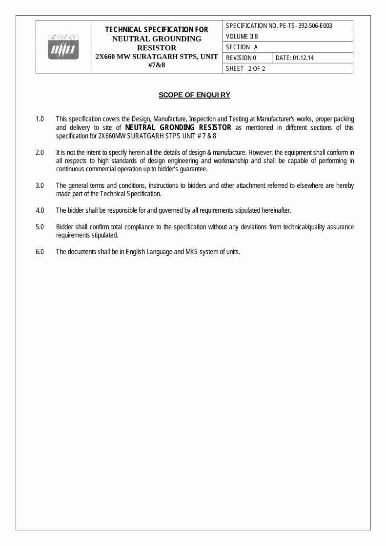
SCOPE OF ENQUIRY
1.0 This specification covers the Design, Manufacture, Inspection and Testing at Manufacturer's works, proper packing
and delivery to site of NEUTRAL GRONDING RESISTOR as mentioned in different sections of this specification for 2X660MW SURATGARH STPS UNIT # 7 & 8
2.0 It is not the intent to specify herein all the details of design & manufacture. However, the equipment shall conform in
all respects to high standards of design engineering and workmanship and shall be capable of performing in continuous commercial operation up to bidder’s guarantee.
3.0 The general terms and conditions, instructions to bidders and other attachment referred to elsewhere are hereby
made part of the Technical Specification.
4.0 The bidder shall be responsible for and governed by all requirements stipulated hereinafter. 5.0 Bidder shall confirm total compliance to the specification without any deviations from technical/quality assurance
requirements stipulated. 6.0 The documents shall be in English Language and MKS system of units.

TECHNICAL SPECIFICATION FOR NEUTRAL GROUNDING RESISTOR
2X660 MW SURATGARH STPS, UNIT #7&8
SPECIFICATION NO. PE-TS-392-506-E003 VOLUME NO. : II-B SECTION : B REV NO. : 0 DATE : 01.12.14 SHEET : 1 OF 04
SECTION - B
PROJECT INFORMATION
SPEC.NO. TCE.5750A-H-500-001 TATA CONSULTING ENGINEERS LIMITED
VOLUME II
SECTION – B
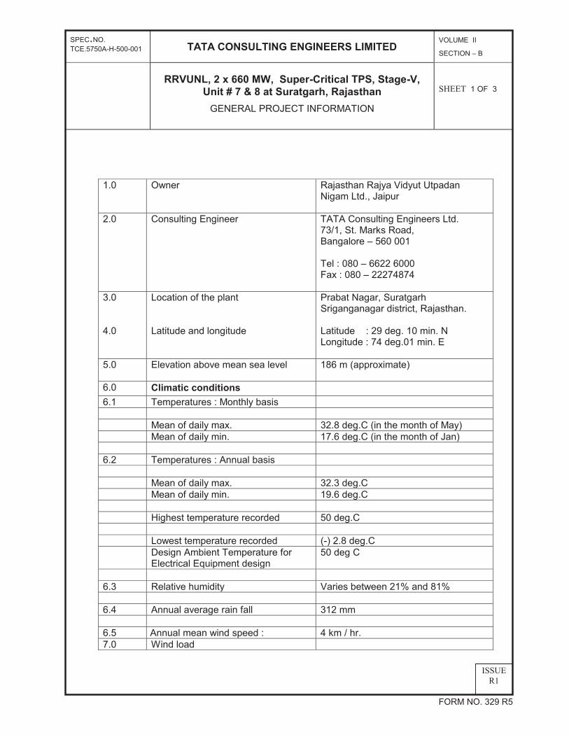
RRVUNL, 2 x 660 MW, Super-Critical TPS, Stage-V,Unit # 7 & 8 at Suratgarh, Rajasthan
GENERAL PROJECT INFORMATION
SHEET 1 OF 3
FORM NO. 329 R5
ISSUER1
1.0 Owner Rajasthan Rajya Vidyut Utpadan
Nigam Ltd., Jaipur
2.0 Consulting Engineer TATA Consulting Engineers Ltd. 73/1, St. Marks Road, Bangalore – 560 001 Tel : 080 – 6622 6000 Fax : 080 – 22274874
3.0 4.0
Location of the plant Latitude and longitude
Prabat Nagar, Suratgarh Sriganganagar district, Rajasthan. Latitude : 29 deg. 10 min. N Longitude : 74 deg.01 min. E
5.0 Elevation above mean sea level 186 m (approximate)
6.0 Climatic conditions 6.1 Temperatures : Monthly basis Mean of daily max. 32.8 deg.C (in the month of May) Mean of daily min. 17.6 deg.C (in the month of Jan) 6.2 Temperatures : Annual basis Mean of daily max. 32.3 deg.C Mean of daily min. 19.6 deg.C Highest temperature recorded 50 deg.C Lowest temperature recorded (-) 2.8 deg.C Design Ambient Temperature for
Electrical Equipment design 50 deg C
6.3 Relative humidity Varies between 21% and 81% 6.4 Annual average rain fall 312 mm 6.5 Annual mean wind speed : 4 km / hr. 7.0 Wind load

SPEC.NO. TCE.5750A-H-500-001 TATA CONSULTING ENGINEERS LIMITED
VOLUME II
SECTION – B
RRVUNL, 2 x 660 MW, Super-Critical TPS, Stage-V,Unit # 7 & 8 at Suratgarh, Rajasthan
GENERAL PROJECT INFORMATION
SHEET 2 OF 3
FORM NO. 329 R5
ISSUER1
Calculations for wind effect shall be in accordance with IS:875-1987(Part-3)
taking into account the following:
a) Basic wind speed = 47 m/sec b) Factor K1 = 1.07 c) Category of terrain = Category 2 d) K3 – as per IS 875
8.0 Seismic data (As per IS: 1893 latest issue)
a) Zone Zone II Designs & design coefficients shall be based on IS 1893:2002 Design condenser cooling water
inlet temperature 33 Deg C
9.0 Auxiliary power supply:
Auxiliary electrical equipment to be supplied against this specification shall be suitable for operation on the following system:
a)
b) c)
For motors rated 160 kW and below. For motors rated above 160 kW and up to 1500 kW For motors rated above 1500kW
415V AC, 3-phase, 3-wire effectively earthed. 6600V AC, 3-phase, 3-wire, 50 Hz, non-effectively earthed 11000V AC, 3-phase, 3-wire, 50 Hz, non-effectively earthed
d) For motor control centres 415V AC, 3-phase, 3/4-wire effectively earthed.
e) DC motor starters, DC solenoids, DC alarm control and protection
220 V DC, 2-wire unearthed
f) AC control & protective devices 110 V 1 phase, 50Hz, 2 wire AC supply. The single phase 110V AC supply shall be derived by VENDOR by providing 415V / 110 V Control transformers of adequate rating with MCCB / MCB on both the primary and secondary sides.
g) Uninterrupted power supply 230 V, 1-phase, 50 Hz, 2-wire, AC
SPEC.NO. TCE.5750A-H-500-001 TATA CONSULTING ENGINEERS LIMITED
VOLUME II
SECTION – B
RRVUNL, 2 x 660 MW, Super-Critical TPS, Stage-V,Unit # 7 & 8 at Suratgarh, Rajasthan
GENERAL PROJECT INFORMATION
SHEET 3 OF 3
FORM NO. 329 R5
ISSUER1
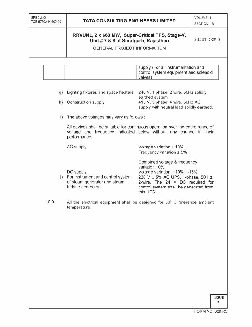
supply (For all instrumentation and control system equipment and solenoid valves)
g) Lighting fixtures and space heaters
240 V, 1 phase, 2 wire, 50Hz,solidly earthed system
h) Construction supply 415 V, 3 phase, 4 wire, 50Hz AC supply with neutral lead solidly earthed.
i) The above voltages may vary as follows :
All devices shall be suitable for continuous operation over the entire range of voltage and frequency indicated below without any change in their performance.
AC supply Voltage variation 10% Frequency variation 5%
Combined voltage & frequency variation 10%
DC supply Voltage variation +10% ,-15% j) For instrument and control system
of steam generator and steam turbine generator.
230 V 5% AC UPS, 1-phase, 50 Hz, 2-wire. The 24 V DC required for control system shall be generated from this UPS.
10.0 All the electrical equipment shall be designed for 50 C reference ambient temperature.

TECHNICAL SPECIFICATION FOR NEUTRAL GROUNDING RESISTOR 2X660 MW SURATGARH STPS,
UNIT #7&8
SPECIFICATION NO. PE-TS- 392-506-E003
VOLUME II B
SECTION C
REVISION 0 DATE: 01.12.14
SHEET 1 OF 2
SECTION –C
SPECIFIC TECHNICAL REQUIREMENTS
TECHNICAL SPECIFICATION FOR NEUTRAL GROUNDING RESISTOR 2X660 MW SURATGARH STPS,
UNIT #7&8
SPECIFICATION NO. PE-TS- 392-506-E003
VOLUME II B
SECTION C
REVISION 0 DATE: 01.12.14
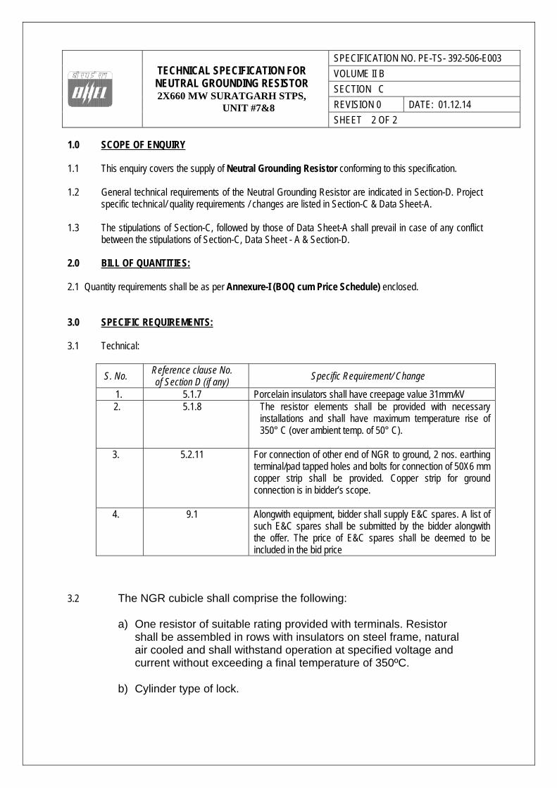
SHEET 2 OF 2 1.0 SCOPE OF ENQUIRY 1.1 This enquiry covers the supply of Neutral Grounding Resistor conforming to this specification. 1.2 General technical requirements of the Neutral Grounding Resistor are indicated in Section-D. Project
specific technical/ quality requirements / changes are listed in Section-C & Data Sheet-A. 1.3 The stipulations of Section-C, followed by those of Data Sheet-A shall prevail in case of any conflict
between the stipulations of Section-C, Data Sheet - A & Section-D. 2.0 BILL OF QUANTITIES: 2.1 Quantity requirements shall be as per Annexure-I (BOQ cum Price Schedule) enclosed. 3.0 SPECIFIC REQUIREMENTS:
3.1 Technical:
S. No. Reference clause No. of Section D (if any)
Specific Requirement/ Change
1. 5.1.7 Porcelain insulators shall have creepage value 31mm/kV 2. 5.1.8 The resistor elements shall be provided with necessary
installations and shall have maximum temperature rise of 350° C (over ambient temp. of 50° C).
3. 5.2.11 For connection of other end of NGR to ground, 2 nos. earthing
terminal/pad tapped holes and bolts for connection of 50X6 mm copper strip shall be provided. Copper strip for ground connection is in bidder’s scope.
4. 9.1 Alongwith equipment, bidder shall supply E&C spares. A list of
such E&C spares shall be submitted by the bidder alongwith the offer. The price of E&C spares shall be deemed to be included in the bid price
3.2 The NGR cubicle shall comprise the following:
a) One resistor of suitable rating provided with terminals. Resistor shall be assembled in rows with insulators on steel frame, natural air cooled and shall withstand operation at specified voltage and current without exceeding a final temperature of 350ºC.
b) Cylinder type of lock.

TECHNICAL SPECIFICATION FOR NEUTRAL GROUNDING RESISTOR 2X660 MW SURATGARH STPS,
UNIT #7&8
SPECIFICATION NO. PE-TS- 392-506-E003
VOLUME II B
SECTION C
REVISION 0 DATE: 01.12.14
SHEET 3 OF 2
c) One earth bus.
d) Standoff insulators 3.3 The resistors shall be provided with taps at 25%, 50% & 75%.
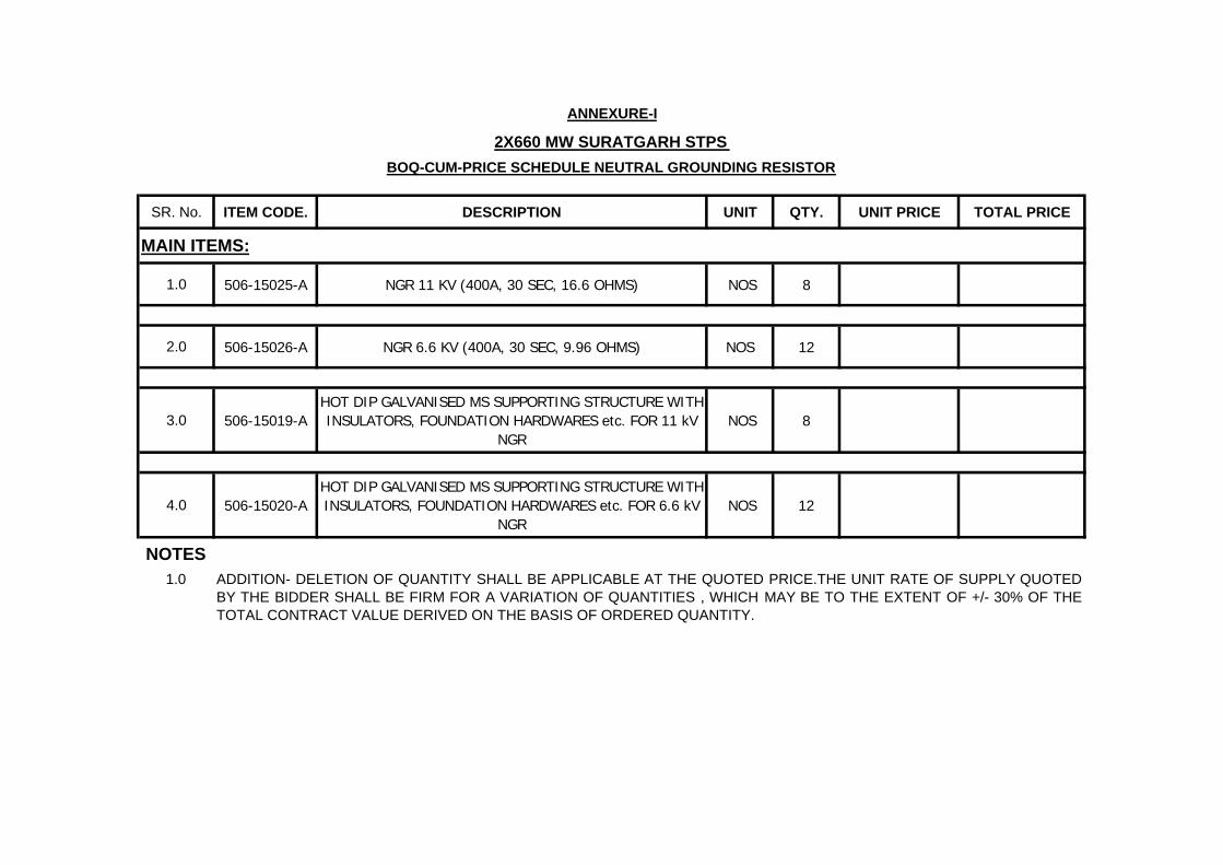
SR. No. ITEM CODE. DESCRIPTION UNIT QTY. UNIT PRICE TOTAL PRICE
1.0 506-15025-A NGR 11 KV (400A, 30 SEC, 16.6 OHMS) NOS 8
2.0 506-15026-A NGR 6.6 KV (400A, 30 SEC, 9.96 OHMS) NOS 12
3.0 506-15019-AHOT DIP GALVANISED MS SUPPORTING STRUCTURE WITH INSULATORS, FOUNDATION HARDWARES etc. FOR 11 kV
NGR NOS 8
4.0 506-15020-AHOT DIP GALVANISED MS SUPPORTING STRUCTURE WITH INSULATORS, FOUNDATION HARDWARES etc. FOR 6.6 kV
NGR NOS 12
NOTES1.0 ADDITION- DELETION OF QUANTITY SHALL BE APPLICABLE AT THE QUOTED PRICE.THE UNIT RATE OF SUPPLY QUOTED
BY THE BIDDER SHALL BE FIRM FOR A VARIATION OF QUANTITIES , WHICH MAY BE TO THE EXTENT OF +/- 30% OF THETOTAL CONTRACT VALUE DERIVED ON THE BASIS OF ORDERED QUANTITY.
ANNEXURE-I
2X660 MW SURATGARH STPS
BOQ-CUM-PRICE SCHEDULE NEUTRAL GROUNDING RESISTOR
MAIN ITEMS:
TECHNICAL SPECIFICATION FOR
NEUTRAL GROUNDING RESISTOR
SPECIFICATION NO. PE-TS-392-506-E003
VOLUME II B
SECTION ---
REVISION 0 DATE: 01.12.14
SHEET 1 OF 1
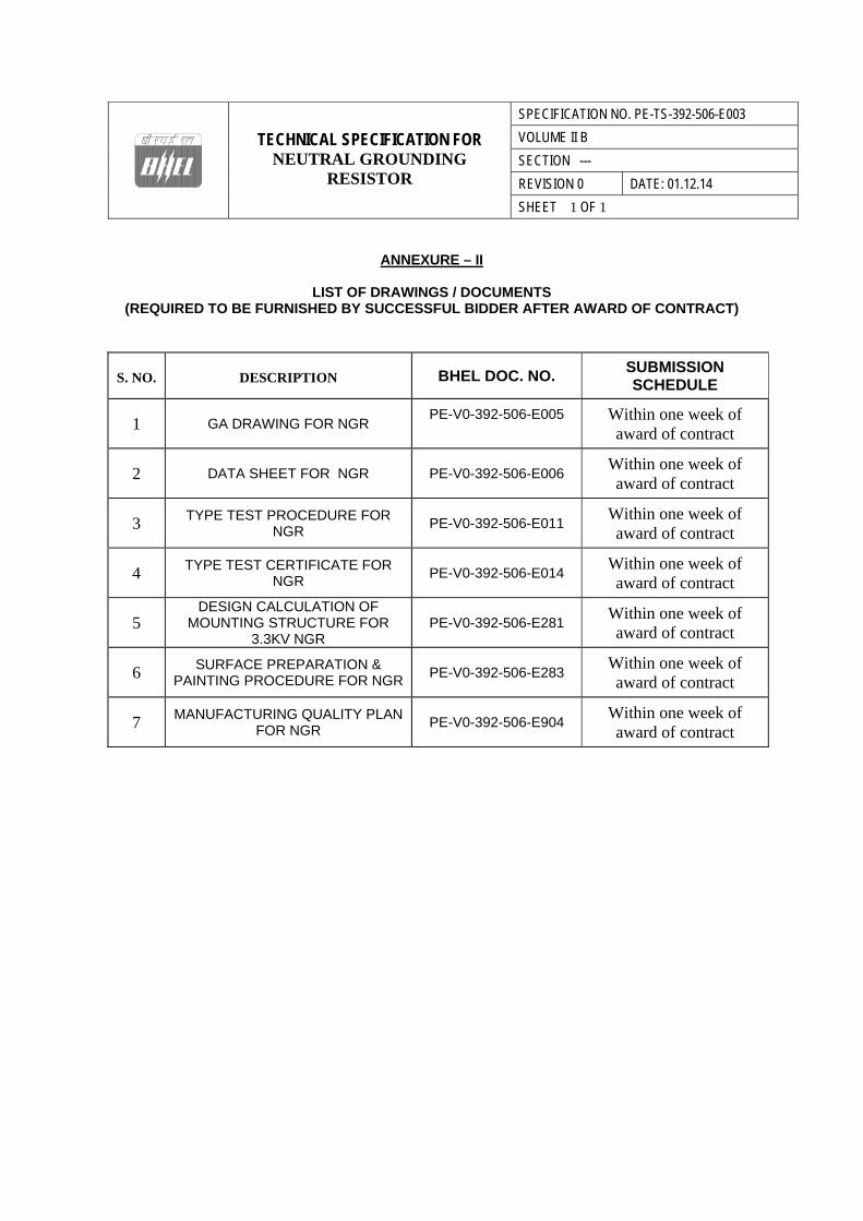
ANNEXURE – II
LIST OF DRAWINGS / DOCUMENTS (REQUIRED TO BE FURNISHED BY SUCCESSFUL BIDDER AFTER AWARD OF CONTRACT)
S. NO.
DESCRIPTION BHEL DOC. NO.
SUBMISSION SCHEDULE
1 GA DRAWING FOR NGR PE-V0-392-506-E005
Within one week of award of contract
2 DATA SHEET FOR NGR PE-V0-392-506-E006 Within one week of award of contract
3 TYPE TEST PROCEDURE FOR NGR
PE-V0-392-506-E011 Within one week of award of contract
4 TYPE TEST CERTIFICATE FOR NGR
PE-V0-392-506-E014 Within one week of award of contract
5 DESIGN CALCULATION OF
MOUNTING STRUCTURE FOR 3.3KV NGR
PE-V0-392-506-E281 Within one week of award of contract
6 SURFACE PREPARATION & PAINTING PROCEDURE FOR NGR
PE-V0-392-506-E283 Within one week of award of contract
7 MANUFACTURING QUALITY PLAN FOR NGR
PE-V0-392-506-E904 Within one week of award of contract
TECHNICAL SPECIFICATION FOR
NEUTRAL GROUNDING RESISTOR
SPECIFICATION NO. PE-TS-392-506-E003
VOLUME II B
SECTION ---
REVISION 0 DATE: 01.12.14
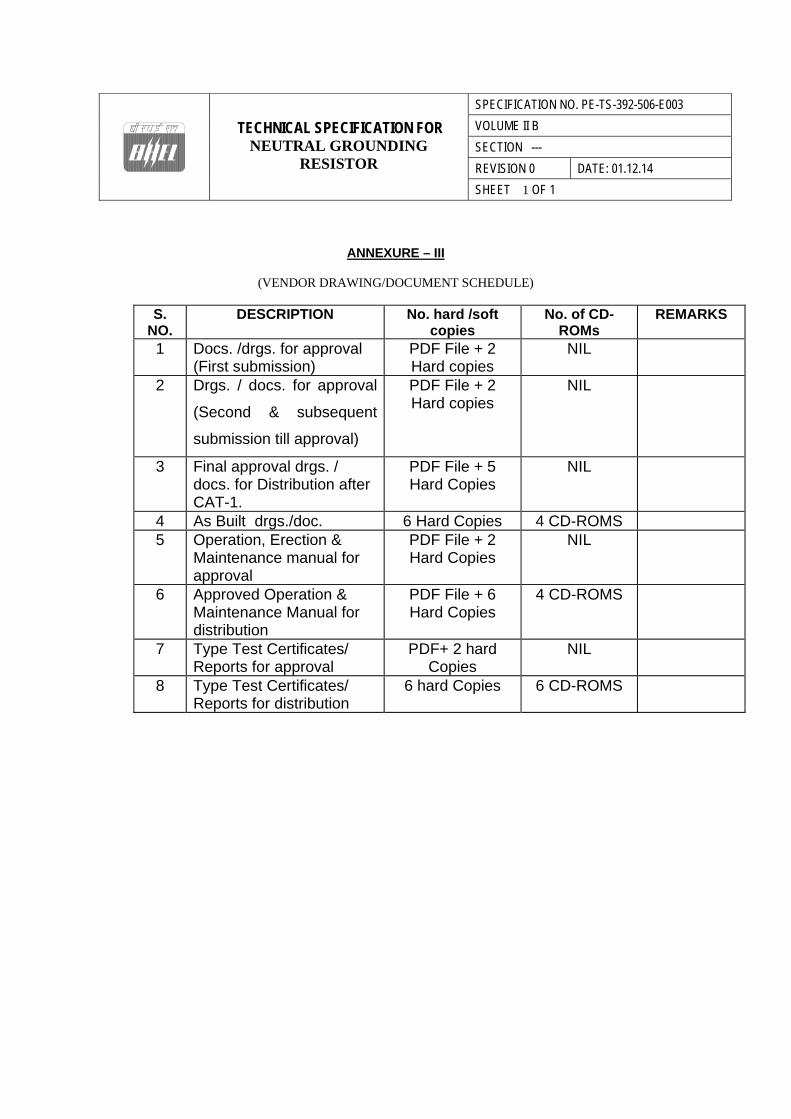
SHEET 1 OF 1 ANNEXURE – III
(VENDOR DRAWING/DOCUMENT SCHEDULE)
S. NO.
DESCRIPTION No. hard /soft copies
No. of CD-ROMs
REMARKS
1 Docs. /drgs. for approval (First submission)
PDF File + 2 Hard copies
NIL
2 Drgs. / docs. for approval
(Second & subsequent
submission till approval)
PDF File + 2 Hard copies
NIL
3 Final approval drgs. / docs. for Distribution after CAT-1.
PDF File + 5 Hard Copies
NIL
4 As Built drgs./doc. 6 Hard Copies 4 CD-ROMS
5 Operation, Erection & Maintenance manual for approval
PDF File + 2 Hard Copies
NIL
6 Approved Operation & Maintenance Manual for distribution
PDF File + 6 Hard Copies
4 CD-ROMS
7 Type Test Certificates/ Reports for approval
PDF+ 2 hard Copies
NIL
8 Type Test Certificates/ Reports for distribution
6 hard Copies 6 CD-ROMS
TECHNICAL SPECIFICATION FOR NEUTRAL GROUNDING RESISTOR 2X660 MW SURATGARH STPS,
UNIT #7&8
SPECIFICATION NO. PE-TS- 392-506-E003
VOLUME II B
SECTION - D
REVISION 0 DATE: 01.12.14
SHEET 1 OF 7
SECTION-D
STANDARD TECHNICAL SPECIFICATION

TECHNICAL SPECIFICATION FOR NEUTRAL GROUNDING RESISTOR 2X660 MW SURATGARH STPS,
UNIT #7&8
SPECIFICATION NO. PE-TS- 392-506-E003
VOLUME II B
SECTION - D
REVISION 0 DATE: 01.12.14
SHEET 2 OF 7 1.0 SCOPE OF ENQUIRY 1.1 This specification covers the design, manufacture, assembly, testing and inspection at vendor’s/sub-
vendor’s works, packing and despatch to site of neutral grounding resistor as described in the various sections of this specification.
1.2 Although erection and commissioning is not included in vendor’s scope, the vendor shall still not be
absolved of his responsibility of establishing the correctness of equipment at site. 2.0 CODES & STANDARDS
2.1 The material, constructional features and various processes involved in manufacture shall comply with latest revision
of Indian Standards. 2.2 The design, material, construction, manufacture, inspection, testing and performance of Neutral Grounding
Resistor shall conform to the latest revision of relevant standards and codes of practices mentioned in Datasheet – A.
2.3 In case of conflict between the applicable reference standard and this specification, this specification shall govern. 3.0 DESIGN REQUIREMENTS AND CONSTRUCTIONAL FEATURES
3.1 The NGR is used for medium resistance grounding of MV (11 / 6.6 / 3.3KV) or LV (415 V) system. NGR shall be connected between earth pit and neutral point of applicable transformer.
3.2 The NGR shall be suitable for limiting the desired value of earth fault current and duty as specified in
BOQ-Cum-Price Schedule/ Datasheet-A.
3.3 The resistor unit shall be natural air-cooled type suitable for installation at outdoor/ indoor locations.
3.4 The NGR will be installed in hot humid and tropical atmosphere. All equipment, accessories and wiring shall be provided with tropical finish to prevent fungus growth.
4.0 TERMINAL POINTS OF SUPPLY:
a) Neutral grounding resistor along with suitable cable glands and lugs for incoming cables from transformer neutral.
b) Supporting structure along with insulators and necessary foundation hardware.
c) Bushing along with tinned copper strip of suitable cross-section (as specified in Datasheet-A / BOQ-cum-
Price Schedule) and connecting hardware for neutral connection of transformer. Copper strip will be applicable only when cable connection is not applicable and vice-versa.
d) All Civil works, Erection & commissioning of equipment are excluded from bidder’s scope.
e) Termination and Jointing kits are excluded from bidder’s cope.
5.0. SPECIFIC TECHNICAL REQUIREMENTS
5.1 NEUTRAL GROUNDING RESISTOR
TECHNICAL SPECIFICATION FOR NEUTRAL GROUNDING RESISTOR 2X660 MW SURATGARH STPS,
UNIT #7&8
SPECIFICATION NO. PE-TS- 392-506-E003
VOLUME II B
SECTION - D
REVISION 0 DATE: 01.12.14
SHEET 3 OF 7
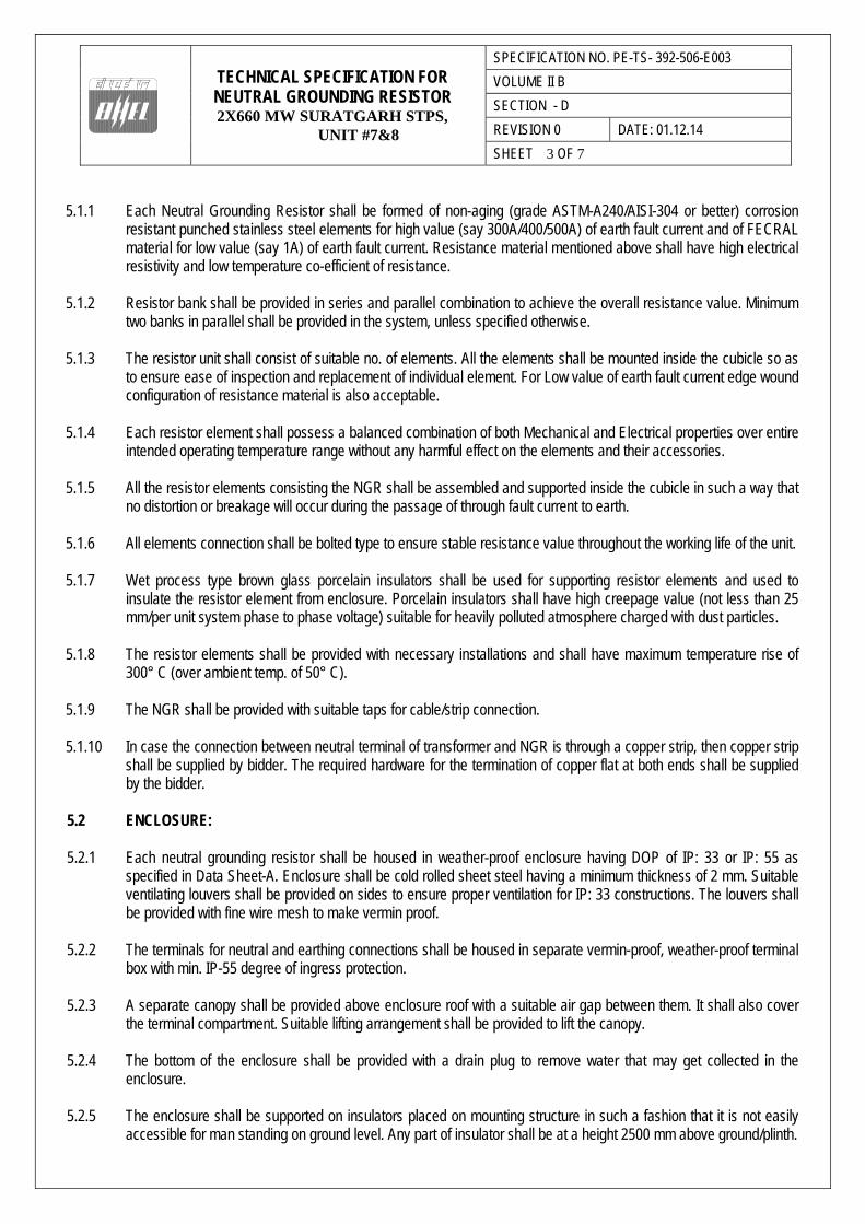
5.1.1 Each Neutral Grounding Resistor shall be formed of non-aging (grade ASTM-A240/AISI-304 or better) corrosion
resistant punched stainless steel elements for high value (say 300A/400/500A) of earth fault current and of FECRAL material for low value (say 1A) of earth fault current. Resistance material mentioned above shall have high electrical resistivity and low temperature co-efficient of resistance.
5.1.2 Resistor bank shall be provided in series and parallel combination to achieve the overall resistance value. Minimum
two banks in parallel shall be provided in the system, unless specified otherwise.
5.1.3 The resistor unit shall consist of suitable no. of elements. All the elements shall be mounted inside the cubicle so as to ensure ease of inspection and replacement of individual element. For Low value of earth fault current edge wound configuration of resistance material is also acceptable.
5.1.4 Each resistor element shall possess a balanced combination of both Mechanical and Electrical properties over entire
intended operating temperature range without any harmful effect on the elements and their accessories.
5.1.5 All the resistor elements consisting the NGR shall be assembled and supported inside the cubicle in such a way that no distortion or breakage will occur during the passage of through fault current to earth.
5.1.6 All elements connection shall be bolted type to ensure stable resistance value throughout the working life of the unit.
5.1.7 Wet process type brown glass porcelain insulators shall be used for supporting resistor elements and used to insulate the resistor element from enclosure. Porcelain insulators shall have high creepage value (not less than 25 mm/per unit system phase to phase voltage) suitable for heavily polluted atmosphere charged with dust particles.
5.1.8 The resistor elements shall be provided with necessary installations and shall have maximum temperature rise of 300° C (over ambient temp. of 50° C).
5.1.9 The NGR shall be provided with suitable taps for cable/strip connection.
5.1.10 In case the connection between neutral terminal of transformer and NGR is through a copper strip, then copper strip shall be supplied by bidder. The required hardware for the termination of copper flat at both ends shall be supplied by the bidder.
5.2 ENCLOSURE:
5.2.1 Each neutral grounding resistor shall be housed in weather-proof enclosure having DOP of IP: 33 or IP: 55 as
specified in Data Sheet-A. Enclosure shall be cold rolled sheet steel having a minimum thickness of 2 mm. Suitable ventilating louvers shall be provided on sides to ensure proper ventilation for IP: 33 constructions. The louvers shall be provided with fine wire mesh to make vermin proof.
5.2.2 The terminals for neutral and earthing connections shall be housed in separate vermin-proof, weather-proof terminal
box with min. IP-55 degree of ingress protection.
5.2.3 A separate canopy shall be provided above enclosure roof with a suitable air gap between them. It shall also cover the terminal compartment. Suitable lifting arrangement shall be provided to lift the canopy.
5.2.4 The bottom of the enclosure shall be provided with a drain plug to remove water that may get collected in the enclosure.
5.2.5 The enclosure shall be supported on insulators placed on mounting structure in such a fashion that it is not easily
accessible for man standing on ground level. Any part of insulator shall be at a height 2500 mm above ground/plinth.
TECHNICAL SPECIFICATION FOR NEUTRAL GROUNDING RESISTOR 2X660 MW SURATGARH STPS,
UNIT #7&8
SPECIFICATION NO. PE-TS- 392-506-E003
VOLUME II B
SECTION - D
REVISION 0 DATE: 01.12.14
SHEET 4 OF 7
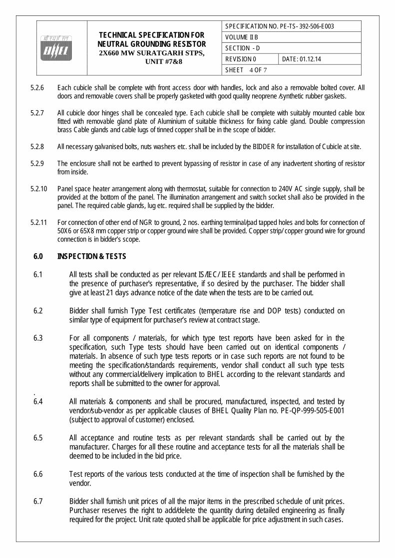
5.2.6 Each cubicle shall be complete with front access door with handles, lock and also a removable bolted cover. All doors and removable covers shall be properly gasketed with good quality neoprene /synthetic rubber gaskets.
5.2.7 All cubicle door hinges shall be concealed type. Each cubicle shall be complete with suitably mounted cable box fitted with removable gland plate of Aluminium of suitable thickness for fixing cable gland. Double compression brass Cable glands and cable lugs of tinned copper shall be in the scope of bidder.
5.2.8 All necessary galvanised bolts, nuts washers etc. shall be included by the BIDDER for installation of Cubicle at site.
5.2.9 The enclosure shall not be earthed to prevent bypassing of resistor in case of any inadvertent shorting of resistor from inside.
5.2.10 Panel space heater arrangement along with thermostat, suitable for connection to 240V AC single supply, shall be provided at the bottom of the panel. The illumination arrangement and switch socket shall also be provided in the panel. The required cable glands, lug etc. required shall be supplied by the bidder.
5.2.11 For connection of other end of NGR to ground, 2 nos. earthing terminal/pad tapped holes and bolts for connection of 50X6 or 65X8 mm copper strip or copper ground wire shall be provided. Copper strip/ copper ground wire for ground connection is in bidder’s scope.
6.0 INSPECTION & TESTS 6.1 All tests shall be conducted as per relevant IS/IEC/ IEEE standards and shall be performed in
the presence of purchaser's representative, if so desired by the purchaser. The bidder shall give at least 21 days advance notice of the date when the tests are to be carried out.
6.2 Bidder shall furnish Type Test certificates (temperature rise and DOP tests) conducted on
similar type of equipment for purchaser’s review at contract stage. 6.3 For all components / materials, for which type test reports have been asked for in the
specification, such Type tests should have been carried out on identical components / materials. In absence of such type tests reports or in case such reports are not found to be meeting the specification/standards requirements, vendor shall conduct all such type tests without any commercial/delivery implication to BHEL according to the relevant standards and reports shall be submitted to the owner for approval.
. 6.4 All materials & components and shall be procured, manufactured, inspected, and tested by
vendor/sub-vendor as per applicable clauses of BHEL Quality Plan no. PE-QP-999-505-E001 (subject to approval of customer) enclosed.
6.5 All acceptance and routine tests as per relevant standards shall be carried out by the
manufacturer. Charges for all these routine and acceptance tests for all the materials shall be deemed to be included in the bid price.
6.6 Test reports of the various tests conducted at the time of inspection shall be furnished by the
vendor. 6.7 Bidder shall furnish unit prices of all the major items in the prescribed schedule of unit prices.
Purchaser reserves the right to add/delete the quantity during detailed engineering as finally required for the project. Unit rate quoted shall be applicable for price adjustment in such cases.

TECHNICAL SPECIFICATION FOR NEUTRAL GROUNDING RESISTOR 2X660 MW SURATGARH STPS,
UNIT #7&8
SPECIFICATION NO. PE-TS- 392-506-E003
VOLUME II B
SECTION - D
REVISION 0 DATE: 01.12.14
SHEET 5 OF 7 6.8 All bought out items shall be procured from reputed manufacturers and shall be subject to
approval of purchaser. 7.0 PAINTING
7.1 All bidders must have 7-tank or 8-tank painting procedure. Well documented painting procedure shall be submitted by bidder for purchaser’s approval.
7.2 All metal parts, surfaces shall be degreased by dipping in hot alkaline solution and rubbed with wire brush
to remove oil and scale and then rinsed in water. Alternatively, they may be shot blasted.
7.3 Parts shall be pickled by dipping in hydrochloric acid to remove the rust from the surfaces formed during storage of sheets and then rinsed to remove traces of the acid. The cleaning and pre-treatment of all metal parts shall be as per applicable standard.
7.4 The surfaces to be painted shall then be prepared by phosphatizing to protect them from further rusting
and to create a good bond with the paint.
7.5 All parts shall then be subjected to a coat of primer paint. All inside surfaces of enclosure shall be spray painted with black matt finish and outside surfaces of enclosure shall be spray painted with hard semi glossy synthetic enamel or power coated (as specified in Datasheet-A) of shade as per Data Sheet A
7.6 Paint thickness shall be minimum 50 microns unless specified otherwise in Data Sheet A.
7.7 Electrostatic or powder painting shall be acceptable subject to purchaser’s approval.
7.8 Finished parts shall be coated with peelable compound by spraying method to protect the finished product from scratches, grease, dirty and oily spots during handling and transportation.
8.0 PACKING
8.1 A detailed write up on the packing procedure as per manufacturer’s practice shall be submitted by the vendor. Vendor shall incorporate all modifications as suggested by the purchaser. Final packing procedure shall be to the approval of purchaser.
8.2 Specification for the sea worthy packing, if enclosed, for the export jobs shall form part of the
specification. 9.0 SPARES
9.1 A list of Erection & commissioning spares along with quantities considered necessary by purchaser is indicated in BOM-cum-Price Schedule.
9.2 The vendor shall indicate any additional start-up and O&M spares and their recommended quantities,
which may be required as per vendor’s usual practice. However, the acceptance of the same shall not be binding on purchaser.
TECHNICAL SPECIFICATION FOR NEUTRAL GROUNDING RESISTOR 2X660 MW SURATGARH STPS,
UNIT #7&8
SPECIFICATION NO. PE-TS- 392-506-E003
VOLUME II B
SECTION - D
REVISION 0 DATE: 01.12.14
SHEET 6 OF 7 10.0 TOOLS & TACKLES
10.1 Tools and tackles that may be required to facilitate assembly adjustment, maintenance and dismantling of equipment supplied shall be provided as part of equipment supplied. List of tools & Tackles to be furnished by bidder.
10.2 The above shall be supplied within the initial consignment of equipment so as to be available prior to erec-
tion. 11.0 GUARANTEED PERFORMANCE REQUIREMENTS
11.1 The vendor shall guarantee satisfactory performance of the equipment supplied under all conditions and requirement as laid down by this specification.
11.2 The vendor shall comply with the general requirements of performance guarantee specified elsewhere.
12.0 O & M MANUAL O & M manual for installation, operation and maintenance of NGR shall be furnished before despatch of the
equipment. Draft O & M manual shall be submitted for purchaser’s approval. Manual shall contain minimum following details:
i) Description of the equipment. ii) Salient construction features.
iii) Packing details.
iv) Instructions to be followed on receipt at site for storage.
v) Erection procedure & checks.
vi) Test to be conducted at site.
vii) Commissioning procedure.
viii) Maintenance instructions.
13.0 DELIVERY The delivery shall be as per NIT (Notice Inviting Tender). 14..0 DOCUMENTATION 14.1 Documents to be submitted by the bidder along with the bid. a) A copy of sheet “Contents” with bidder’s signature & company stamp.
b) A copy of sheet “Instructions to bidders for preparing Technical offer” with bidder’s signature & company stamp. c) Unpriced copy of “Annexure-I (Bill of Quantities)” with bidder’s signature & company stamp.
TECHNICAL SPECIFICATION FOR NEUTRAL GROUNDING RESISTOR 2X660 MW SURATGARH STPS,
UNIT #7&8
SPECIFICATION NO. PE-TS- 392-506-E003
VOLUME II B
SECTION - D
REVISION 0 DATE: 01.12.14
SHEET 7 OF 7
No other documentation is required to be submitted as technical offer. Any information contained in other parts of the offer (e.g. covering letter, annexures, etc.) which is deviating from specification requirements in any way shall not be considered by BHEL as part of offer.
14.2 Documents to be submitted by successful bidder after award of contract shall be as per Annexure-II. 14.3 Vendor drawing / document schedule for the project shall be as per Annexure – III.
TECHNICAL SPECIFICATION FOR NEUTRAL GROUNDING RESISTOR 2X660 MW SURATGARH STPS,
UNIT #7&8
SPECIFICATION NO. PE-TS-392-506-E003
VOLUME II B
SECTION - D
REVISION 0 DATE: 01.12.14
SHEET 1 OF 1
TECHNICAL DATASHEET-A (SPECIFIC TECHNICAL REQUIREMENTS)
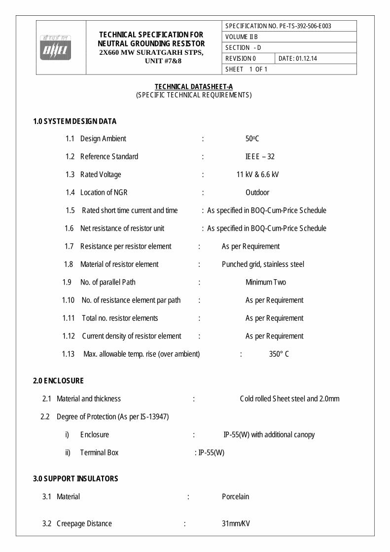
1.0 SYSTEM DESIGN DATA
1.1 Design Ambient : 50oC
1.2 Reference Standard : IEEE – 32
1.3 Rated Voltage : 11 kV & 6.6 kV 1.4 Location of NGR : Outdoor
1.5 Rated short time current and time : As specified in BOQ-Cum-Price Schedule
1.6 Net resistance of resistor unit : As specified in BOQ-Cum-Price Schedule
1.7 Resistance per resistor element : As per Requirement 1.8 Material of resistor element : Punched grid, stainless steel
1.9 No. of parallel Path : Minimum Two 1.10 No. of resistance element par path : As per Requirement 1.11 Total no. resistor elements : As per Requirement 1.12 Current density of resistor element : As per Requirement 1.13 Max. allowable temp. rise (over ambient) : 350° C
2.0 ENCLOSURE
2.1 Material and thickness : Cold rolled Sheet steel and 2.0mm
2.2 Degree of Protection (As per IS-13947)
i) Enclosure : IP-55(W) with additional canopy
ii) Terminal Box : IP-55(W)
3.0 SUPPORT INSULATORS
3.1 Material : Porcelain
3.2 Creepage Distance : 31mm/KV
TECHNICAL SPECIFICATION FOR NEUTRAL GROUNDING RESISTOR 2X660 MW SURATGARH STPS,
UNIT #7&8
SPECIFICATION NO. PE-TS-392-506-E003
VOLUME II B
SECTION - D
REVISION 0 DATE: 01.12.14
SHEET 1 OF 1
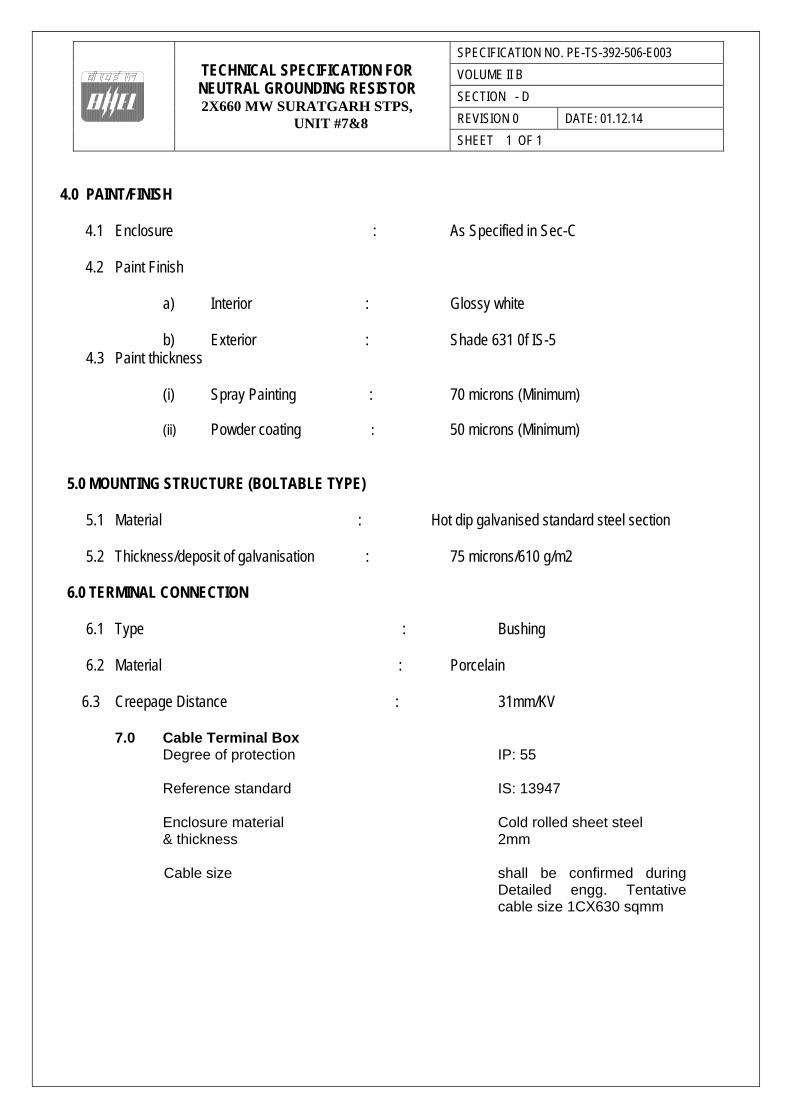
4.0 PAINT/FINISH 4.1 Enclosure : As Specified in Sec-C 4.2 Paint Finish
a) Interior : Glossy white b) Exterior : Shade 631 0f IS-5
4.3 Paint thickness
(i) Spray Painting : 70 microns (Minimum) (ii) Powder coating : 50 microns (Minimum)
5.0 MOUNTING STRUCTURE (BOLTABLE TYPE)
5.1 Material : Hot dip galvanised standard steel section
5.2 Thickness/deposit of galvanisation : 75 microns/610 g/m2
6.0 TERMINAL CONNECTION
6.1 Type : Bushing
6.2 Material : Porcelain
6.3 Creepage Distance : 31mm/KV
7.0 Cable Terminal Box Degree of protection IP: 55 Reference standard IS: 13947 Enclosure material Cold rolled sheet steel & thickness 2mm Cable size shall be confirmed during
Detailed engg. Tentative cable size 1CX630 sqmm
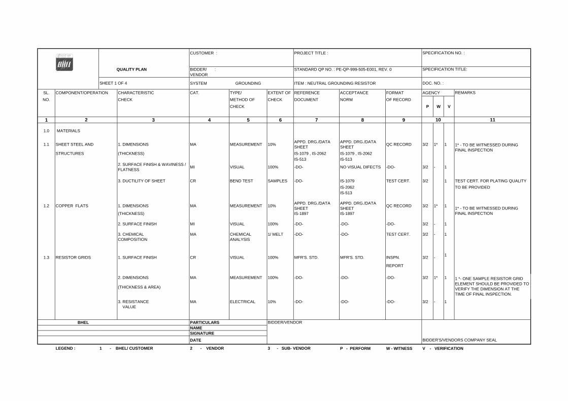
CUSTOMER : PROJECT TITLE :
QUALITY PLAN BIDDER/ : STANDARD QP NO. : PE-QP-999-505-E001, REV. 0VENDOR
SYSTEM GROUNDING ITEM : NEUTRAL GROUNDING RESISTOR
SL. COMPONENT/OPERATION CHARACTERISTIC CAT. TYPE/ EXTENT OF REFERENCE ACCEPTANCE FORMAT AGENCY
NO. CHECK METHOD OF CHECK DOCUMENT NORM OF RECORD
CHECK P W V
1 3 4 5 6 7 8 9
1.0 MATERIALS
1.1 SHEET STEEL AND 1. DIMENSIONS MA MEASUREMENT 10%APPD. DRG./DATA SHEET
APPD. DRG./DATA SHEET
QC RECORD 3/2 1* 1
STRUCTURES (THICKNESS) IS-1079 , IS-2062 IS-1079 , IS-2062
IS-513 IS-5132. SURFACE FINISH & WAVINESS / FLATNESS
MI VISUAL 100% -DO- NO VISUAL DIFECTS -DO- 3/2 - 1
3. DUCTILITY OF SHEET CR BEND TEST SAMPLES -DO- IS-1079 TEST CERT. 3/2 1 TEST CERT. FOR PLATING QUALITY
IS-2062 TO BE PROVIDED IS-513
1.2 COPPER FLATS 1. DIMENSIONS MA MEASUREMENT 10%APPD. DRG./DATA SHEET
APPD. DRG./DATA SHEET
QC RECORD 3/2 1* 1
(THICKNESS) IS-1897 IS-1897
2. SURFACE FINISH MI VISUAL 100% -DO- -DO- -DO- 3/2 - 1
3. CHEMICAL MA CHEMICAL 1/ MELT -DO- -DO- TEST CERT. 3/2 - 1COMPOSITION ANALYSIS
1.3 RESISTOR GRIDS 1. SURFACE FINISH CR VISUAL 100% MFR'S. STD. MFR'S. STD. INSPN. 3/2 -1
REPORT
2. DIMENSIONS MA MEASUREMENT 100% -DO- -DO- -DO- 3/2 1* 1
(THICKNESS & AREA)
3. RESISTANCE MA ELECTRICAL 10% -DO- -DO- -DO- 3/2 - 1 VALUE
BHEL PARTICULARSNAMESIGNATURE
DATE
P - PERFORM W - WITNESS V - VERIFICATION
2 10
LEGEND : 1 - BHEL/ CUSTOMER 2 - VENDOR 3 - SUB- VENDOR
SPECIFICATION NO. :
SPECIFICATION TITLE:
DOC. NO. :
REMARKS
SHEET 1 OF 4
BIDDER'S/VENDORS COMPANY SEAL
BIDDER/VENDOR
11
1* - TO BE WITNESSED DURING FINAL INSPECTION
1* - TO BE WITNESSED DURING FINAL INSPECTION
1 *- ONE SAMPLE RESISTOR GRID ELEMENT SHOULD BE PROVIDED TO VERIFY THE DIMENSION AT THE TIME OF FINAL INSPECTION.
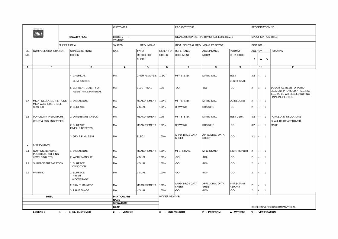
CUSTOMER : PROJECT TITLE :
QUALITY PLAN BIDDER/ : STANDARD QP NO. : PE-QP-999-505-E001, REV. 0VENDOR
SYSTEM GROUNDING ITEM : NEUTRAL GROUNDING RESISTOR
SL. COMPONENT/OPERATION CHARACTERISTIC CAT. TYPE/ EXTENT OF REFERENCE ACCEPTANCE FORMAT AGENCY
NO. CHECK METHOD OF CHECK DOCUMENT NORM OF RECORD
CHECK P W V
1 3 4 5 6 7 8 9
4. CHEMICAL MA CHEM ANALYSIS 1/ LOT MFR'S. STD. MFR'S. STD. TEST 3/2 - 1
COMPOSITION CERTIFICATE
5. CURRENT DENSITY OF MA ELECTRICAL 10% -DO- -DO- -DO- 2 1* 1
RESISTANCE MATERIAL
1.4 MICA INSULATED TIE-RODS 1. DIMENSIONS MA MEASUREMENT 100% MFR'S. STD. MFR'S. STD. QC RECORD 2 - 1MICA WASHERS, STEEL WASHER 2. SURFACE MA VISUAL 100% DRAWING DRAWING -DO- 2 - 1
1.5 PORCELAIN INSULATORS 1. DIMENSIONS CHECK MA MEASUREMENT 10% MFR'S. STD. MFR'S. STD. TEST CERT. 3/2 - 1 PORCELAIN INSULATORS
(POST & BUSHING TYPES) SHALL BE OF APPROVED
2. SURFACE MA MEASUREMENT 100% DRAWING DRAWING -DO- 3/2 - 1 MAKEFINISH & DEFECTS
3. DRY P.F. HV TEST MA ELEC. 100%APPD. DRG./ DATA SHEET
APPD. DRG./ DATA SHEET
-DO- 3/2 - 1
2 FABRICATION
2.1 CUTTING, BENDING, 1. DIMENSIONS MA MEASUREMENT 100% MFG. STAND. MFG. STAND. INSPN REPORT 2 - 1PUNCHING, DRILLING& WELDING ETC 2. WORK MANSHIP MA VISUAL 100% -DO- -DO- -DO- 2 - 1
2.2 SURFACE PREPARATION 1. SURFACE MA VISUAL 100% -DO- -DO- -DO- 2 - 1 CONDITION
2.3 PAINTING 1. SURFACE MA VISUAL 100% -DO- -DO- -DO- 2 - 1 FINISH
& COVERAGE
2. FILM THICKNESS MA MEASUREMENT 100%APPD. DRG./ DATA SHEET
APPD. DRG./ DATA SHEET
INSPECTION REPORT
2 - 1
3. PAINT SHADE MA VISUAL 100% -DO- -DO- -DO- 2 - 1
BHEL PARTICULARSNAMESIGNATURE
DATE
P - PERFORM W - WITNESS V - VERIFICATION2 - VENDOR 3 - SUB- VENDOR
SHEET 2 OF 4
2 10
BIDDER'S/VENDORS COMPANY SEAL
LEGEND : 1 - BHEL/ CUSTOMER
BIDDER/VENDOR
SPECIFICATION NO. :
SPECIFICATION TITLE:
DOC. NO. :
REMARKS
1*. SAMPLE RESISTOR GRID ELEMENT PROVIDED AT S.L. NO. 1.3.2 TO BE WITNESSED DURING FINAL INSPECTION.
11

CUSTOMER : PROJECT TITLE :
QUALITY PLAN BIDDER/ : STANDARD QP NO. : PE-QP-999-505-E001, REV. 0VENDOR
SYSTEM GROUNDING ITEM : NEUTRAL GROUNDING RESISTOR
SL. COMPONENT/OPERATION CHARACTERISTIC CAT. TYPE/ EXTENT OF REFERENCE ACCEPTANCE FORMAT AGENCY
NO. CHECK METHOD OF CHECK DOCUMENT NORM OF RECORD
CHECK P W V
1 3 4 5 6 7 8 9
3 SUB-ASSEMBLY
3.1 RESISTOR UNIT FRAME 1. HV TEST CR ELECTRICAL 100%APPD. DRG./ DATA SHEET
APPD. DRG./ DATA SHEET
TEST 2 - 1
ASSEMBLED BS-587 BS-587 REPORT
2.RESISTANCE CR ELECTRICAL 100% -DO- -DO- -DO- 2 - 1 VALUE
3. DIMENSIONS MA MEASUREMENT 100% MFG. STAND. MFG. STAND. -DO- 2 - 1
3.2 1. FITMENT MA VISUAL 100%APPD. DRG./ DATA SHEET
APPD. DRG./ DATA SHEET
INSPECTION REPORT
2 - 1
2.DIMENSION MA MEASUREMENT 100% -DO- -DO- -DO- 2 - 1
3. CONNECTION MA VISUAL 100% -DO- -DO- -DO- 2 - 1
4. TERMINATION MA MEASUREMENT 100% -DO- -DO- -DO- 2 - 1
5. RESISTANCE VALUE MA ELECTRICAL 100% -DO- -DO- -DO- 2 - 1
3.3 1. FINISH MA VISUAL 100%APPD. DRG./ DATA SHEET
APPD. DRG./ DATA SHEET
INSPECTION REPORT
2 - 1
2.DIMENSION MA MEASUREMENT 100% -DO- -DO- -DO- 2 - 1
3. PAINT SHADE MA VISUAL 100% -DO- -DO- -DO- 2 - 1
4 FINAL ASSEMBLY
4.1 COMPLETE NGR 1. HV TEST CR ELECTRICAL 100%APPD. DRG./ DATA SHEET
APPD. DRG./ DATA SHEET
TEST 2 1 -
BS-587 / STD. IEEE 32 BS-587 / STD. IEEE 32 REPORT
2. MEAUSERMENT OF IR VALUE BEFORE & AFTER HV TEST
CR ELECTRICAL 100% -DO- -DO- 2 1 -
3. RESISTANCE VALUE CR ELECTRICAL 100% -DO- -DO- 2 1 -
4. DIMENSIONS MA MEASUREMENT 100% -DO- -DO- 2 1 -
BHEL PARTICULARSNAMESIGNATURE
DATE
P - PERFORM W - WITNESS V - VERIFICATION
SHEET 3 OF 4 DOC. NO. :
REMARKS
BIDDER/VENDOR
ENCLOSURE & ITS PARTS
FITTING OF RESISTOR UNIT FRAME, PORCELAIN BUSHING & POST INSULATOR
BIDDER'S/VENDORS COMPANY SEAL
LEGEND : 1 - BHEL/ CUSTOMER 2 - VENDOR
SPECIFICATION NO. :
SPECIFICATION TITLE:
2 10 11
3 - SUB- VENDOR

CUSTOMER : PROJECT TITLE :
QUALITY PLAN BIDDER/ : STANDARD QP NO. : PE-QP-999-505-E001, REV. 0VENDOR
SYSTEM GROUNDING ITEM : NEUTRAL GROUNDING RESISTOR
SL. COMPONENT/OPERATION CHARACTERISTIC CAT. TYPE/ EXTENT OF REFERENCE ACCEPTANCE FORMAT AGENCY
NO. CHECK METHOD OF CHECK DOCUMENT NORM OF RECORD
CHECK P W V
1 3 4 5 6 7 8 9
5. SHORT TIME MA HEAT RUN 1/TYPEAPPD. DRG./ DATA SHEET
APPD. DRG./ DATA SHEET
2 1* 1**
RATING / TEMPER- BS:587 BS:587 ATURE RISE TEST
6. DEGREE OF MA AS PER 1/TYPE TEST 2 1* 1** PROTECTION IS:12063 REPORT
IEC:60529
7. PAINT FINISH MA VISUAL 100%INSPECTION REPORT
2 1 -
8. PAINT MA MEASURMENT ALL -DO- -DO- -DO- 2 1 - THICKNESS
9. PAINT SHADE MI VISUAL-SHADE ALL -DO- -DO- -DO- 2 1 -CARD
10. PAINT ADHESION TEST MI MECHANICALFEW PLACES OF ALL NGR
-DO- -DO- -DO- 2 1 -
11. THICKNESS OF GALVANISINGS OF STRUCTURE
MIVISUAL / MEASURMENT
100% TEST REPORT 2 1 -
12. CHECKING OF EARTH MA ELECTRICAL 100% -DO- 2 1CONNECTION
13. CHECKING OF MA VISUAL 100% -DO- 2 1EARTHING MATERIAL(TINNED COPPER STRIP)
14. VERIFICATION OF BOM MA VISUAL 100% -DO- 2 1INCLUDING CABLE GLAND & LUGS (AS APPLICABLE)
BHEL PARTICULARSNAMESIGNATURE
DATE
P - PERFORM W - WITNESS V - VERIFICATION
TESTREPORT
SPECIFICATION TITLE:
-DO- -DO-
-DO- -DO-
-DO- -DO-
APPD. DRG./ DATA SHEET
APPD. DRG./ DATA SHEET
APPD. DRG./ DATA SHEET
APPD. DRG./ DATA SHEET
2 10
APPD. DRG./ DATA SHEET
APPD. DRG./ DATA SHEET
1**. TYPE TEST CERTIFICATE OFSIMILAR RATING TO BE FURNISHEDFOR VERIFICATION BYENGINEERING1* CONDUCTION OF TYPE TEST TOBE DONE IF CALLED FOR INTECHNICAL SPECIFICATION & TESTREPORT OF THE SAME TO BEFURNISHED FOR VERIFICATION BYENGINEERING.
BIDDER/VENDOR
BIDDER'S/VENDORS COMPANY SEAL
LEGEND : 1 - BHEL/ CUSTOMER 2 - VENDOR 3 - SUB- VENDOR
SPECIFICATION NO. :
SHEET 4 OF 4 DOC. NO. :
REMARKS
11

ANNEXURE – 1
INSTRUCTIONS FOR QUALITY PLAN
The Quality Plan shall include all the Quality Control Measures and Checks adopted by the Vendor to ensure that the material/component/assembly/services supplied by him meet/will meet the requirements as per specifications and good practices. They shall include all stages of operation such as materials, processes, manufacture, assembly, packing and despatch. The following guide lines may be noted:
Column 1- Serial Number
Column 2- Component/Operation- The component and/or operation being checked shall be given here.
Column 3- Characteristics check- The characteristics being checked shall be given here, e.g., chemical composition, mechanical properties, leak tightness, surface defects etc..
Column 4- Category -‘CR’ stands for critical characteristic - affecting safety of equipment and personnel
‘MA’ stands for major Characteristic - affecting safety of equipment and personnel
‘MI’ stands for minor characteristic - affecting appearance etc.
Column 5- Type/Method of check e.g. chemical analysis tensile testing, hydraulic test, visual examination radiography etc.
Column 6- Extent of check, such as, 100, 10, 1 percent etc.
Column 7- Reference Documents - Documents, such as technical specification, drawings, standard specifications (IS, BS ETC.) procedure, etc. according to which check is done.
Column 8- Acceptance Norms - Standards etc. according to which acceptability or otherwise of the characteristics being checked is decided.
Column 9- Format of Record - Formats, log shets, reports, etc. in which the observations are recorded. Standard log sheets, reports, formats etc. of the Vendors shall be numbered and such reference numbers shall be included here.
Column 10- Agency - The agency which performs the test/instruction shall be written in sub-column ‘W’ The agency which verifies test certificates/inspection records and carries out audit check of the components/operation shall
be written in sub-column ‘V’
The agencies are codified as 1,2 & 3
‘1’ stands for (BHEL)
‘1’ * means the operation shall be cleared by BHEL before the start of the next operation.
‘2’ Stands for Vendor
‘3’ stands for sub-Vendor of the Vendor and so on.
Example :
Entry ‘3’ in column ‘P’ means test./inspection to be performed by sub-Vendor’s QC
Entry ‘2’ in column ‘W’ means test./inspection to be witnessed by Vendor’s QC
Entry ‘1’ in column ‘V’ means verification shall be done by BHEL and next stage to be started only after the hold point is cleared by BHEL
Column11I- Remarks - Any special remarks shall be given here.
NOTES :
1. In absence of correlation with the test certificate(s) (e.g. material identification) samples shall be drawn bgy BHEL and all tests as per relevent specifications shall be carried out in their presence or in recognized Government Laboratory.
2. When materials and components are initially identified and stamped by BHEL QS engineer, the identification marks shall be presserved till despatch. Wherever this is not possible, the identification mark shall be transferred to the components in the presence of BHEL QS Engineer unless other wise agreed.
3. For castings and forgings integral test specimens shall be provided, When this is not possible for casting, they shall be poured in the presence of BHEL QS Engineer unless otherwise, if witnessing of test by BHEL is called for.
4. When welders qualified by reputed inspection agencies or statutory bodies are not available, qualification tests shall be conducted in the presence of BHEL QS Engineer.
5. This Quality Plan is liable to be modified as per the requirements of approved drawings and changes in technical specifications/drawings. If there are contradictions in respect of column 7 & 8 between this Quality Plan and the approved drawings specifications, the latter shall prevail.
6. Wherever inspection by BHELs Purchaser/Third Party/Statutory authorities are mandatory, this shall be compiled with.
7. Inspection reports, log sheets, test reports/certificate. etc. shall be furnished to BHEL at the approproate stages or at the time of final inspection, as required.
8. This Quality Plan is also applicable to spares, if any, under scope of supply of Vendor.
9. The quality plan shall be submitted in minimum 4 copies with a soft copy of the same or in line with contract requirements.