new method of capacitors failure detection and location in
TRANSCRIPT

New Method of Capacitors Failure Detection and
Location in Shunt Capacitor Banks
Hesam Jouybari-Moghaddam – Western Universit y
Tarlochan Sidhu –Universit y of Ontario Inst itute of Technology
Ilia Voloh –GE Grid Solut ions
Mohammad Zadeh - ETAP
2018 Texas A&M Protective Relaying Conference

Outline
• Introduction
• Superimposed Reactance method-Ungrounded wye banks-Grounded wye banks
• Self-tuning process: periodic and during failures
• Method Flowchart
• Simulation model and method evaluation for different configurations
• Conclusions 2

Introduction• Transient over voltages, temperature
changes, manufacturing defects can cause internal failures of capacitor units
• The search of the faulty capacitor can in a large high voltage capacitor bank can take significant time and should be reduced to expedite the repair process
• Fuseless and internally fused designs do not have any visual indication for the failures
• Unbalance methods are the most sensitive methods used to detect capacitors failures.
• Detecting consecutive and ambiguousfailures, live reporting of number of failedelements helps for preventive maintenanceand thus reducing unscheduled outages
3

• Ungrounded (a)
• Grounded (b and c)
Different Grounding Configurations
N
XA XB XC
ABC
VN
VP
IG
RXN VN VR
N N
(a)(b) (c)
4

Estimate the neutral voltage assuming a A-phase failure (apply Kirchhoff’s Current Law to the neutral node)
Ungrounded banks
5

Ungrounded banks
Superimposed Reactance (SR)
Rewrite and use simplifying terms (calibrating factors)
6
and are calibrating factors pλpγ

• For self-tuning we need to update and factors • Two unknowns, two equations (real and imaginary)
• For the faulted phase SR angle has to be near approach zero value
• SR magnitude indicates the number of failed elements
p: phase p (A, B or C)pf: phase p after failure
Ungrounded banks
( ) ( )A AB N B C N C N AV V K V V K V V− + − = −
1p p pfSpup
pf pf
X X XX
X X−
= − =
ACKA
BK
7

• Adjustments for direction of change in reactance
𝐾𝐾𝑎𝑎𝑎𝑎𝑎𝑎 = +1−1
𝑓𝑓𝑓𝑓𝑓𝑓𝑓𝑓𝑓𝑓𝑓𝑓𝑓𝑓𝑓𝑓𝑖𝑖𝑖𝑖𝑖𝑖𝑓𝑓𝑖𝑖𝑖𝑖𝑎𝑎𝑓𝑓𝑓𝑓𝑖𝑖 𝑓𝑓𝑓𝑓𝑓𝑓𝑓𝑓𝑎𝑎
Ungrounded banks: capacitors types
Fusing TypeInternally Fused Reactance Mag.
Fuseless,Externally fused
Reactance Mag.
Spuadj pK XDecision making quantity
8

Self-tuning process: periodic and after failure
Update the k-factors(supervised)
K-factor Calculations
Update the calibrating factors
Balance out (reset) the SR
Failure Detection Calculations
Calibrating Factors Calculations
( ) ( )A AB N B C N C N AV V K V V K V V− + − = −
1 A AA B CK Kλ = + +
0 0( 1)( ) ( 1)( )A AA B B C CK V V K V Vγ = − − + − −
0( )Spu A A NA
N A
V VXV V
γ λ− −=
−
9

• Self tuning is applied (updating the k-factors) once a failure is detected
• SR would be reset upon detection
• Method is ready for detection of subsequent failures
Capacitor Failure Dependent Self-tuning
Time
Angle Zone
Magnitude Threshold
Capacitor Element(s) Failure
Fault Location Determined; SR Reset Applied
Counting Scheme Angle
Mag.
10
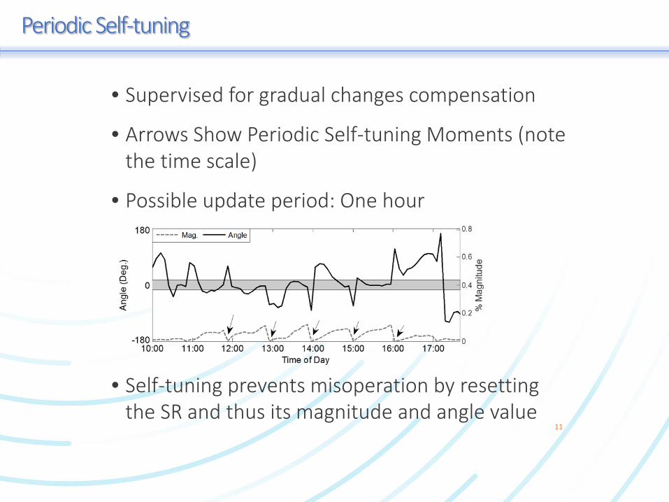
• Self-tuning prevents misoperation by resetting the SR and thus its magnitude and angle value
• Supervised for gradual changes compensation
• Arrows Show Periodic Self-tuning Moments (note the time scale)
• Possible update period: One hour
Periodic Self-tuning
11

Superimposed Reactance method flowchart
Blockk-factor Updates
Report Affected Phase
Report Number of Fai led Element s
Re-calculate the k-factors
Phase Angle Evaluation
Count ing Scheme
Calculat ion of
Magnitude Thresholds
Unbalance Protection
Inputs
Sett ing Calibrat ing
Factors
Time Stamped Events Sequence
HMI/SCADA
Multifunctional Numerical SCB Relay
Annunciators
12

Simulation Model
Internally Fused bank
Fuseless
62 ...
...
...14
3
1.36µF
2
.....
Unit
12
5
...
1
6
60.8µF
.........
...
...
Unit
100 MVA
230 KV 50 km 50 km
SCB
Feeder
13

• Unbalance load
• Pre-existing inherent unbalance
• Harmonics
• Measurement noise
• Impact of temperature (could be shading) or aging
Validation: PSCAD and Relay models
The PSCAD model has considered:
• Anti-aliasing filter
• Decaying DC removal
• Full cycle DFT
The Relay model applies:
14

Ungrounded banks: Method Evaluation
0.2 0.25 0.3 0.35 0.4-180
0
180(a) Phase A
Ang
le (D
eg.)
00.20.40.60.8
% M
agni
tude
Angle Magnitude
0.2 0.25 0.3 0.35 0.4-180
0
180Phase B
Ang
le (D
eg.)
00.20.40.60.8
% M
agni
tude
0.2 0.25 0.3 0.35 0.4-180
0
180Phase C
Ang
le (D
eg.)
00.20.40.60.8
% M
agni
tude
0.2 0.25 0.3 0.35 0.40
1
2
3(b)
Num
ber
Time (s)
A B C
Failure in phase A
1
Double failure in phase B
2
Consecutive failure in phase A
3
Double failure in phase C
4
15

• A third K-factor shows up
• It is much larger than phase K-factors• It has trivial changes upon capacitor failures in
each phase• As a result, it will have a constant value in the
algorithm (IEEE C37.99)
Grounded banks (via capacitor)
ppN
N
XK
X=
0 0( ) pp p N NSpu
pN p
V V K VX
V Vγ λ− − −
=−
16

Grounded Bank via Cap: Method Evaluation
0.2 0.25 0.3 0.35 0.4 0.45-180
0
180(a) Phase A
Ang
le (D
eg.)
00.20.40.60.8
% M
agni
tude
Angle Magnitude
0.2 0.25 0.3 0.35 0.4 0.45-180
0
180Phase B
Ang
le (D
eg.)
00.20.40.60.8
% M
agni
tude
0.2 0.25 0.3 0.35 0.4 0.45-180
0
180 Phase C
Ang
le (D
eg.)
00.20.40.60.8
% M
agni
tude
0.2 0.25 0.3 0.35 0.4 0.450123
(b)
Num
ber
Time (s)
A B C
Capacitor Failure in Phase A1
Phase A Open Pole due to external faut
2
3 Phase A reclosed
17

• The phase reactance shows up
• Phase reactance has minor changes after element failures
• Can be considered as the rated value (IEEE C37.99)
Grounded banks (via CT)
A ASpu A B B C C RA
A
V V K V K jXVXV
+ + +=
−
18

Grounded Bank via CT: Method Evaluation
• A noticeable failure (Unit) and a subsequent minor (Element) failure detected
• Verifying the applicability of constant rated reactance assumption in detection principle (SR)
0.2 0.25 0.3 0.35 0.4 0.45-180
0
180(a)
Ang
le (D
eg.)
0
2
4
6
8
% M
agni
tude
Angle Magnitude
0.2 0.25 0.3 0.35 0.4 0.450
2
4
6
8(b)
Num
ber
Time(s)A Capacitor unit fails in Phase A
1
AC System Fault2
AC Fault cleared4
A Capacitor Element fails in Phase A3
19

• Externally fused units are more susceptible tocascadingcapacitor element failures
• An intact or blown fuse does not always meanhealthy or failed capacitor unit
• Failed elements remain as short circuits
• Superimposed Reactance can provide advancealarms for preventive maintenance
Application to Externally Fused Banks
2000 MVAX/R=5.0
138 kV 138kV / 33kV
25 MVar
20 Ω
0.008 H
20

Application to Externally Fused Banks
0.2 0.25 0.3 0.35 0.4-180
0
180(a) Phase A
Ang
le (D
eg.)
00.150.30.450.6
% M
agni
tude
Angle Magnitude
0.2 0.25 0.3 0.35 0.4-180
0
180 Phase BA
ngle
(Deg
.)
00.150.30.450.6
% M
agni
tude
0.2 0.25 0.3 0.35 0.4-180
0
180 Phase C
Ang
le (D
eg.)
00.150.30.450.6
% M
agni
tude
0.2 0.25 0.3 0.35 0.40123
(b)
Num
ber
Time (s)
A B C
One element fails in phase A
1
Two elements fail in phase C2
3 Consecutive failure in phase C
Consecutive failure in phase A4
21

Validation
PSCAD, NI cDAQ and LabVIEW were used to apply waveforms to the relay

• Superimposed Reactance faulted phase detection method for internally fused and fuseless wye capacitor banks is presented to expedite the repair process
• Superimposed Reactance provides advance maintenance alarms for externally fused banks
• Superimposed Reactance can be used for both grounded and ungrounded banks
• Superimposed Reactance faulted phase detection method applies self-tuning and auto-setting that result in: Detecting consecutive failures Detecting ambiguous failures
Conclusions
23

Compensating for gradual capacitance change due to temperature changes or aging Compensating for errors due to the PT/CTs by
initial setting (commissioning process)
• Both magnitude and phase angle of the SR quantityare used to detect capacitor element failures, makingmethod robust even during external disturbancessimultaneously with internal failures.
• Method is immune to external disturbances, noise,bank inherent unbalance, measurementinaccuracies.
• Real time report of number of failed elements andlocation enables quick response for repair
Conclusions
24

Thank You
Questions?
25