new insights into additive manufacturing processes
TRANSCRIPT
Schmuland 1 27th
Annual AIAA/USU
Conference on Small Satellites
SSC13-VII-4
New Insights Into Additive Manufacturing Processes: Enabling Low-Cost, High-Impulse
Propulsion Systems
Derek Schmuland, Christian Carpenter, Robert Masse, Jonathan Overly
Aerojet
11411 139th
Place NE Redmond, WA 98052; 425-869-4546
ABSTRACT
Recent propulsion system trade studies conducted have concluded that traditional chemical propulsion systems,
when scaled down to CubeSat sizes, deliver vanishingly small amounts of impulse per unit volume, even when the
smallest available COTS components are assumed. This effectively has created a barrier that seemingly can only be
broken with the employment of cold gas systems, due to their reduction and simplification of propulsion system
components and the relative ease of the system design itself. Further disadvantages of chemical propulsion systems
have included toxicity-related handling restrictions, barring most mission planners from considering these types of
systems for secondary payload propulsion trade studies. Use of low-toxicity alternatives has been hindered by a
disparity between the typically very limited power budget of nanosatellites and the associated high preheat
temperatures required with current state-of-the-art green ionic liquid monopropellant thrusters. Aerojet has
developed a comprehensive solution by demonstrating that additive manufacturing processes, combined with
miniaturization of propulsion system components, can be employed to break through this barrier by multi-purposing
the system structure to replace traditional add-on components, maximizing the use of dry volume, and minimizing
the number of overall components and required assembly steps. This results in a propulsion system that can be
packaged into a 1U volume that can bolt onto, or be integrated within, a standard CubeSat chassis, for costs low
enough to support the simplest of missions. This system can be tailored for multiple levels of ΔV capability,
depending on the mission planner’s requirements, by employing a variety of propellants ranging from cold-gas
condensable, hydrazine monopropellant, or AF-M315E green advanced monopropellant. This results in ample ΔV
capability to enable CubeSat missions like orbital debris management, constellation deployment, scattering and
coalescence, or simple drag-makeup to support newly-emerging low altitude imaging applications. This system has
been designed from the start with input from range safety personnel to ensure compliance to AFSCM91-710.
INTRODUCTION
The CubeSat platform has greatly reduced the barrier to
entry for space missions, resulting in significant market
growth. Many low cost launch opportunities are
available for CubeSats and as a result the number of
CubeSats launched is increasing significantly each year.
The use of COTS parts with standard interfaces and
components has demonstrated a significant reduction in
development costs and schedules examples include
NSF-funded missions such as (CSSWE, Firefly,
CINEMA, etc.) and NASA funded missions such as
PhoneSat, where the total cost of components was
under $7,000.
Due to a lack of high-impulse propulsive capabilities,
CubeSat missions are effectively confined to their
dispersal orbits. Without propulsion the CubeSat
platform cannot realize its total addressable market,
which will limit the exponential growth that CubeSats
have enjoyed in recent years. Propulsive capabilities
enable the CubeSat platform to access the wider range
of missions that will strengthen the value proposition of
the platform and ensure continued explosive growth in
the market. Propulsive capabilities ranging from
~10m/s for small dispersal maneuvers to >200m/s for
large apogee maneuvers are required. To further
compound the problem, recent propulsion system trade
studies conducted have concluded that traditional
chemical propulsion systems, when scaled down to
CubeSat sizes, deliver vanishingly small amounts of
total impulse per unit volume, even when the smallest
available COTS components are assumed.1
Aerojet has developed a comprehensive solution by
demonstrating that additive manufacturing processes,
together with highly miniaturized system components,
can be employed to create a product line of high-
impulse CubeSat Modular Propulsion Systems (MPS)
that package within CubeSat volumes and satisfy the
propulsive needs of the CubeSat community. The
product line simplifies propulsion mission planning and
integration along with enabling more rideshare
flexibility so that any level of CubeSat builder can
consider a propulsive mission.
Schmuland 2 27th
Annual AIAA/USU
Conference on Small Satellites
PRODUCT LINE OVERVIEW
In 2011, Aerojet began development of a 1U modular
propulsion system called the CubeSat High-impulse
Adaptable Modular Propulsion System (CHAMPS)
designated “MRS-142” to address the emerging need
for CubeSat propulsion systems.2,3
Leveraging designs
and components developed for the MRS-142 along with
key new technologies enabled Aerojet to develop the
CubeSat Modular Propulsion Systems product line
shown in Table 1. The systems leverage common parts
and designs in order to reduce non-recurring
engineering and to achieve economies of scale that will
enable reduced cost and lead times as product line
production rates increase. The objective of the CubeSat
MPS product line is to simplify mission planning,
system selection, and satellite integration to the point
that any level of CubeSat builder can consider a
propulsive mission. This objective is accomplished
through the following features:
Catalog of standard systems with clear propulsive
capabilities listed
“U” based form factor that enables simple
mechanical interfacing
Elimination of requirement for fluidic connections
typically required of the tightly integrated
propulsion systems found on larger satellites
Propulsion system control unit with a single power
and data connection that simplifies electrical and
software integration
ENABLING TECHNOLOGICAL INNOVATIONS
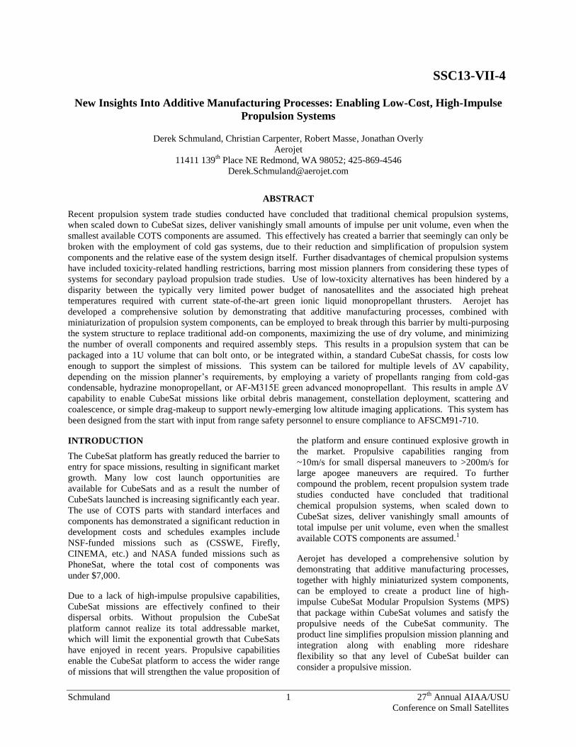
Miniaturized Rocket Engine Technology
Aerojet investments to commercialize technologies
stemming from small form factor missile defense
applications has enabled miniature rocket engines and
valves capable of supporting CubeSat missions. The
resulting MR-14X series of engines realizes a ~4X
reduction in volume as shown in Figure 1. Aerojet’s
efforts to adapt miniature rocket engine technology for
AF-M315E propellant enable both hydrazine and AF-
M315E solutions.
Figure 1: Aerojet Miniature Rocket Engine
Compared with a Standard Rocket Engine
Table 1: CubeSat Modular Propulsion Systems Product Line
Product
Image
Product
Number
Description V for 3U
4kg BOL
V for 6U
10kg BOL
MPS-110 • System Mass: Varies depending on selected size• Propellant: Inert gas• Propulsion: 1 to 4 cold gas thrusters
10 m/s N/A
MPS-120 • System Mass: <1.3kg dry, <1.6kg wet• Propellant: Hydrazine• Propulsion: Four 0.26—2.8 N (BOL) rocket engines
209 m/s 81 m/s
MPS-130 • System Mass: <1.3kg dry, <1.6kg wet• Propellant: AF-M315E• Propulsion: Four TBD—1 N (BOL) rocket engines
340 m/s 130 m/s
MPS-120XW • System Mass: <2.4kg dry, <3.2kg wet• Propellant: Hydrazine• Propulsion: Four 0.26—2.8 N (BOL) rocket engines
440 m/s 166 m/s
MPS-120XL • System Mass: <2.4kg dry, <3.2kg wet• Propellant: Hydrazine• Propulsion: Four 0.26—2.8 N (BOL) rocket engines
539 m/s 200 m/s
MPS-160 • System Mass: TBD• Propellant: Xenon• Propulsion: 80W Solar Electric Power/Solar
Electric Propulsion System (SEP2)
N/A >2,000 m/sImage
Coming Soon
Schmuland 3 27th
Annual AIAA/USU
Conference on Small Satellites
Additive Manufacturing Process Infusion
Subtractive manufacturing is a generic term used to
describe a manufacturing process that removes material
from a piece of stock in order to fabricate a part.
Examples of subtractive manufacturing processes
include: milling, turning, cutting, and drilling. In
contrast, Additive manufacturing is a generic term used
to describe a manufacturing process that deposits and
bonds material together to fabricate a part. Additive
manufacturing processes produce parts directly from a
digital design. Additive manufactured parts typically
require little or no tooling, significantly reducing the
cost and lead time of designing, manufacturing, and
maintaining tools. If fixtures or tooling are needed they
can typically be fabricated during the build process,
minimizing the need to create tools ahead of the build
or maintain them after the build. The reduced
requirement for tooling significantly reduces setup time
and cost as well as inventory costs. Additive
manufacturing processes typically consume only the
material needed to make the part. Typically, most
residual material used during the process is re-usable
for fabrication of future batches of parts. Additive
manufacturing eliminates the need for cutting fluids
that are required in subtractive manufacturing
processes. The combination of efficient use of material
and elimination of support fluids results in significant
reductions in material cost and waste. Overall, additive
manufacturing process benefits can realize significant
reductions in fabrication time and cost. These benefits
enable opportunities for more design iterations than
traditionally possible, enabling lower cost development
programs with higher quality design outputs that are
typically ready for direct transition to low volume
production. These characteristics are of high
importance to the typically long duration, high cost
development programs and ultimately low volume
production of spacecraft systems.
Current additive manufacturing machines are
constrained to build envelopes of ~30 cm3. The MPS-
100 product line includes propulsion systems that fit the
standard 1U CubeSat envelope of ~10 cm x 10 cm x 10
cm, making these systems ideal candidates for
demonstration and infusion of additive manufacturing
process technology. Aerojet has embraced the use of
additive manufacturing methods and has begun infusion
of new design philosophies and manufacturing
processes to develop more affordable propulsion
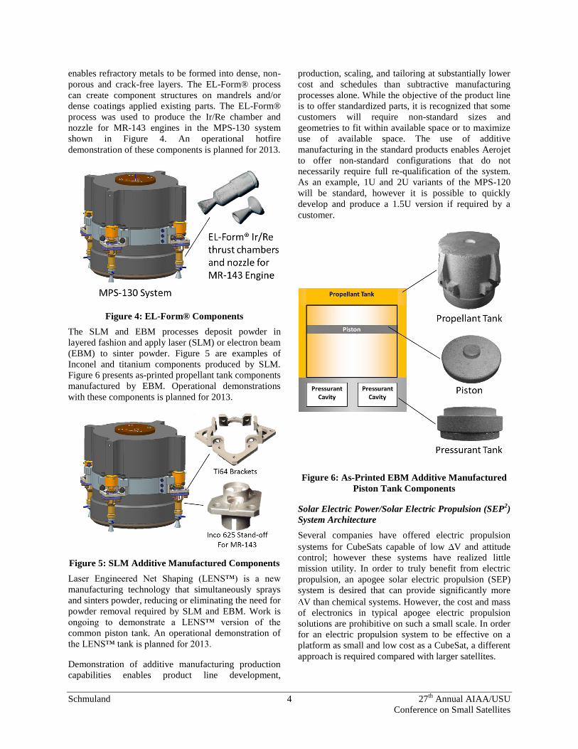
systems. The MPS-120 and MPS-130 liquid propulsion
systems utilize a piston tank that includes a piston,
propellant tank, and pressurant tank. Some components
include internal flow passages that were identified as
opportunities for improvements with additive
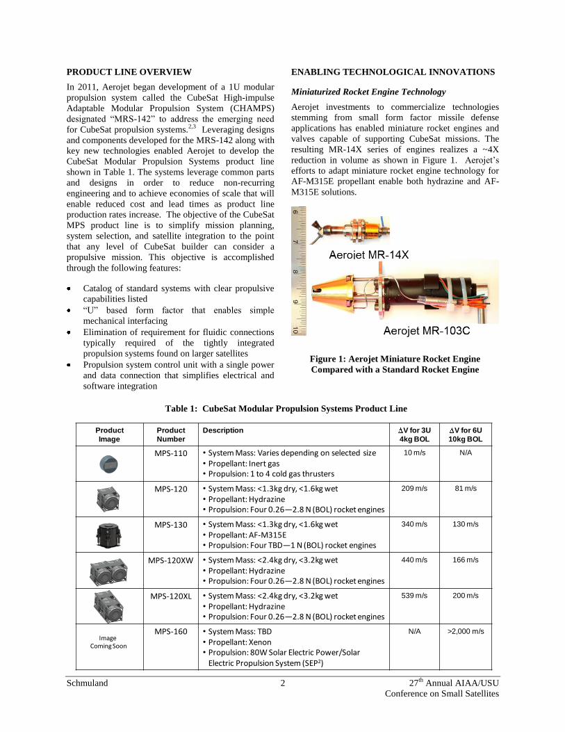
manufacturing. Figure 2 shows how design for additive
manufacturing enables improvements that reduce
component count and eliminate potential leak paths in
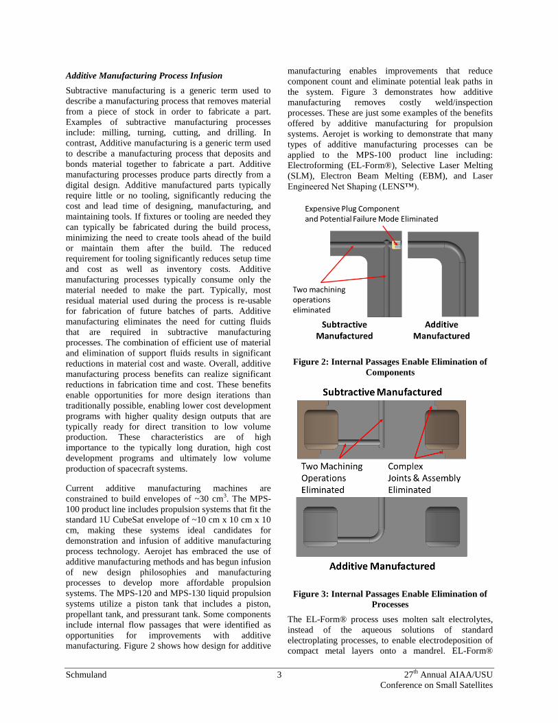
the system. Figure 3 demonstrates how additive
manufacturing removes costly weld/inspection
processes. These are just some examples of the benefits
offered by additive manufacturing for propulsion
systems. Aerojet is working to demonstrate that many
types of additive manufacturing processes can be
applied to the MPS-100 product line including:
Electroforming (EL-Form®), Selective Laser Melting
(SLM), Electron Beam Melting (EBM), and Laser
Engineered Net Shaping (LENS™).
Figure 2: Internal Passages Enable Elimination of
Components
Figure 3: Internal Passages Enable Elimination of
Processes
The EL-Form® process uses molten salt electrolytes,
instead of the aqueous solutions of standard
electroplating processes, to enable electrodeposition of
compact metal layers onto a mandrel. EL-Form®
Schmuland 4 27th
Annual AIAA/USU
Conference on Small Satellites
enables refractory metals to be formed into dense, non-
porous and crack-free layers. The EL-Form® process
can create component structures on mandrels and/or
dense coatings applied existing parts. The EL-Form®
process was used to produce the Ir/Re chamber and
nozzle for MR-143 engines in the MPS-130 system
shown in Figure 4. An operational hotfire
demonstration of these components is planned for 2013.
Figure 4: EL-Form® Components
The SLM and EBM processes deposit powder in
layered fashion and apply laser (SLM) or electron beam
(EBM) to sinter powder. Figure 5 are examples of
Inconel and titanium components produced by SLM.
Figure 6 presents as-printed propellant tank components
manufactured by EBM. Operational demonstrations
with these components is planned for 2013.
Figure 5: SLM Additive Manufactured Components
Laser Engineered Net Shaping (LENS™) is a new
manufacturing technology that simultaneously sprays
and sinters powder, reducing or eliminating the need for
powder removal required by SLM and EBM. Work is
ongoing to demonstrate a LENS™ version of the
common piston tank. An operational demonstration of
the LENS™ tank is planned for 2013.
Demonstration of additive manufacturing production
capabilities enables product line development,
production, scaling, and tailoring at substantially lower
cost and schedules than subtractive manufacturing
processes alone. While the objective of the product line
is to offer standardized parts, it is recognized that some
customers will require non-standard sizes and
geometries to fit within available space or to maximize
use of available space. The use of additive
manufacturing in the standard products enables Aerojet
to offer non-standard configurations that do not
necessarily require full re-qualification of the system.
As an example, 1U and 2U variants of the MPS-120
will be standard, however it is possible to quickly
develop and produce a 1.5U version if required by a
customer.
Figure 6: As-Printed EBM Additive Manufactured
Piston Tank Components
Solar Electric Power/Solar Electric Propulsion (SEP2)
System Architecture
Several companies have offered electric propulsion
systems for CubeSats capable of low V and attitude
control; however these systems have realized little
mission utility. In order to truly benefit from electric
propulsion, an apogee solar electric propulsion (SEP)
system is desired that can provide significantly more
V than chemical systems. However, the cost and mass
of electronics in typical apogee electric propulsion
solutions are prohibitive on such a small scale. In order
for an electric propulsion system to be effective on a
platform as small and low cost as a CubeSat, a different
approach is required compared with larger satellites.
Schmuland 5 27th
Annual AIAA/USU
Conference on Small Satellites
For several years, Aerojet has been working on a
technology called Direct Drive which operates electric
thrusters directly from high voltage solar arrays in an
attempt to boost efficiency, reduce components, and
reduce waste heat. Previous Direct Drive development
activities have focused on multi-kilowatt systems.4
However, the same technology applied to the CubeSat
platform significantly reduces the mass and cost of
power electronics to the point that primary electric
propulsion on CubeSats becomes feasible. An
integrated solar power system and direct drive solar
electric propulsion control unit enabled Solar Electric
Power and Solar Electric Propulsion (SEP2) system
enables electric propulsion apogee systems for
CubeSats. Figure 7 is an example comparison of a
traditional solar electric propulsion system with
Aerojet’s SEP2 system concept.
Figure 7: Comparison of Traditional and SEP
2
Systems
MODULAR PROPULSION SYSTEM PRODUCT
DESCRIPTIONS
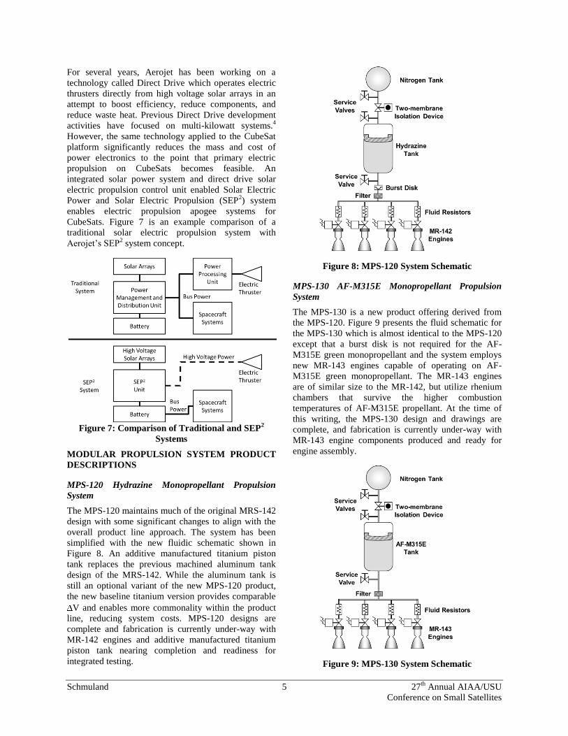
MPS-120 Hydrazine Monopropellant Propulsion
System
The MPS-120 maintains much of the original MRS-142
design with some significant changes to align with the
overall product line approach. The system has been
simplified with the new fluidic schematic shown in
Figure 8. An additive manufactured titanium piston
tank replaces the previous machined aluminum tank
design of the MRS-142. While the aluminum tank is
still an optional variant of the new MPS-120 product,
the new baseline titanium version provides comparable
V and enables more commonality within the product
line, reducing system costs. MPS-120 designs are
complete and fabrication is currently under-way with
MR-142 engines and additive manufactured titanium
piston tank nearing completion and readiness for
integrated testing.
Figure 8: MPS-120 System Schematic
MPS-130 AF-M315E Monopropellant Propulsion
System
The MPS-130 is a new product offering derived from
the MPS-120. Figure 9 presents the fluid schematic for
the MPS-130 which is almost identical to the MPS-120
except that a burst disk is not required for the AF-
M315E green monopropellant and the system employs
new MR-143 engines capable of operating on AF-
M315E green monopropellant. The MR-143 engines
are of similar size to the MR-142, but utilize rhenium
chambers that survive the higher combustion
temperatures of AF-M315E propellant. At the time of
this writing, the MPS-130 design and drawings are
complete, and fabrication is currently under-way with
MR-143 engine components produced and ready for
engine assembly.
Figure 9: MPS-130 System Schematic

Schmuland 6 27th
Annual AIAA/USU
Conference on Small Satellites
MPS-110 Cold Gas System
The MPS-110 Cold Gas system is being developed to
provide a propulsive capability for missions on small
platforms that need minimal V to achieve their
mission objectives. Applications would primarily be
initial dispersion, minor orbit adjustments, or attitude
control. The MPS-110 system derives valves, filter, and
tank design from the MPS-120 system mentioned
previously. Figure 10 is the fluidic schematic of the
MPS-110. The system is capable of operating with a
variety of pressurants such as GN2 or condensables
enabling significant mission tailoring. MPS-110
pressurants have been selected and operational
behaviors are well understood.
Figure 10: MPS-110 System Schematic
MPS-160 Electric Propulsion System
The MPS-160 is a concept system that differs
significantly from the systems presented thus far in that
it is a 2U system that includes both power and
propulsion using the aforementioned SEP2 system
architecture. The MPS-160 concept development is
aimed at developing such a system that would
ultimately be capable of providing >2,000m/s to a 6U
CubeSat from a 2U propulsion and power package.
Figure 11 presents the MPS-160 system schematic. A
Hall thruster is used to represent the apogee propulsion;
however multiple types of electric thrusters are
applicable. Hall thrusters, gridded ion thrusters, and
other types of thrusters are in development at the
power, voltage, and specific impulse levels required by
the MPS-160 system enabling the system to support a
wide range of missions.
Figure 11: MPS-160 System Schematic
MISSION APPLICATIONS
Missions Requiring Dispersal
Every satellite begins its mission life with a deployment
event from the launch vehicle upper stage, and to
prevent re-contact after a number of orbits if the upper
stage is not actively de-orbited, propulsive maneuvers
are typically employed by the satellite to assure that
collision does not occur with the upper stage.
Alternatively, some satellite missions may desire to
conduct propulsive maneuvers to “scatter” away from
the larger upper stage, which can easily be tracked by
amateur radio operators and launch trackers. Secondary
payloads to date typically reserve any minimal ΔV
capability found with cold gas systems for utmost
critical mission events like attitude control or end-of-
life de-orbit requirements. High-impulse propulsion
systems, such as the MPS-120 CHAMPS, can provide
secondary payloads with the tactical advantages that
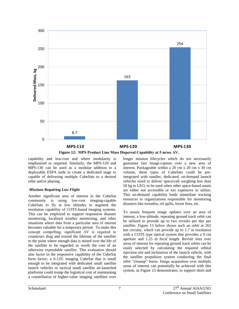
larger satellites have enjoyed for decades. Figure 12
shows the dispersal capabilities of Aerojet’s CubeSat
Modular Propulsion Systems product line to impart 5
m/sec of V to the maximum satellite mass that is
achievable. This amount of ΔV is considered the
minimum needed to achieve safe and tactical
deployment, and also matches the typical 5 m/sec
achieved from a CubeSat P-POD jettison event. Two
observations can be made from this figure: the MPS-
110 cold gas system is adequate in providing enough
ΔV for most 3U CubeSats and some 6U CubeSats for
dispersal applications, and the MPS-120 and MPS-130
can be integrated on satellites much larger than
CubeSats to gain tactical dispersal capability for low
cost compared to custom propulsion system solutions.
This is very compelling for missions for smallsats in the
range of 50-300 kg that are designed for simple mission
Schmuland 7 27th
Annual AIAA/USU
Conference on Small Satellites
capability and low-cost and where modularity is
emphasized or required. Similarly, the MPS-120 and
MPS-130 can be used as a modular addition to a
deployable ESPA node to create a dedicated stage to
capable of delivering multiple CubeSats to a desired
orbit and/or phasing.
Missions Requiring Low Flight
Another significant area of interest in the CubeSat
community is using low-cost imaging-capable
CubeSats to fly at low altitudes to augment the
resolution capability of COTS-based imaging systems.
This can be employed to support responsive disaster
monitoring, localized weather monitoring, and other
situations where data from a particular area of interest
becomes valuable for a temporary period. To make this
concept compelling, significant ΔV is required to
counteract drag and extend the lifetime of the satellite
to the point where enough data is mined over the life of
the satellite to be regarded as worth the cost of an
otherwise expendable satellite. This evaluation should
also factor in the responsive capability of the CubeSat
form factor; a 6-12U imaging CubeSat that is small
enough to be integrated with dedicated small satellite
launch vehicles or tactical small satellite air-launched
platforms could trump the logistical cost of maintaining
a constellation of higher-value imaging satellites over
longer mission lifecycles which do not necessarily
guarantee fast image-capture over a new area of
interest. Packageable within a 20 cm x 20 cm x 30 cm
volume, these types of CubeSats could be pre-
integrated with smaller, dedicated, on-demand launch
vehicles sized to deliver spacecraft weighing less than
50 kg to LEO, to be used when other space-based assets
are either not accessible or too expensive to utilize.
This on-demand capability lends immediate tracking
resources to organizations responsible for monitoring
disasters like tornados, oil spills, forest fires, etc.
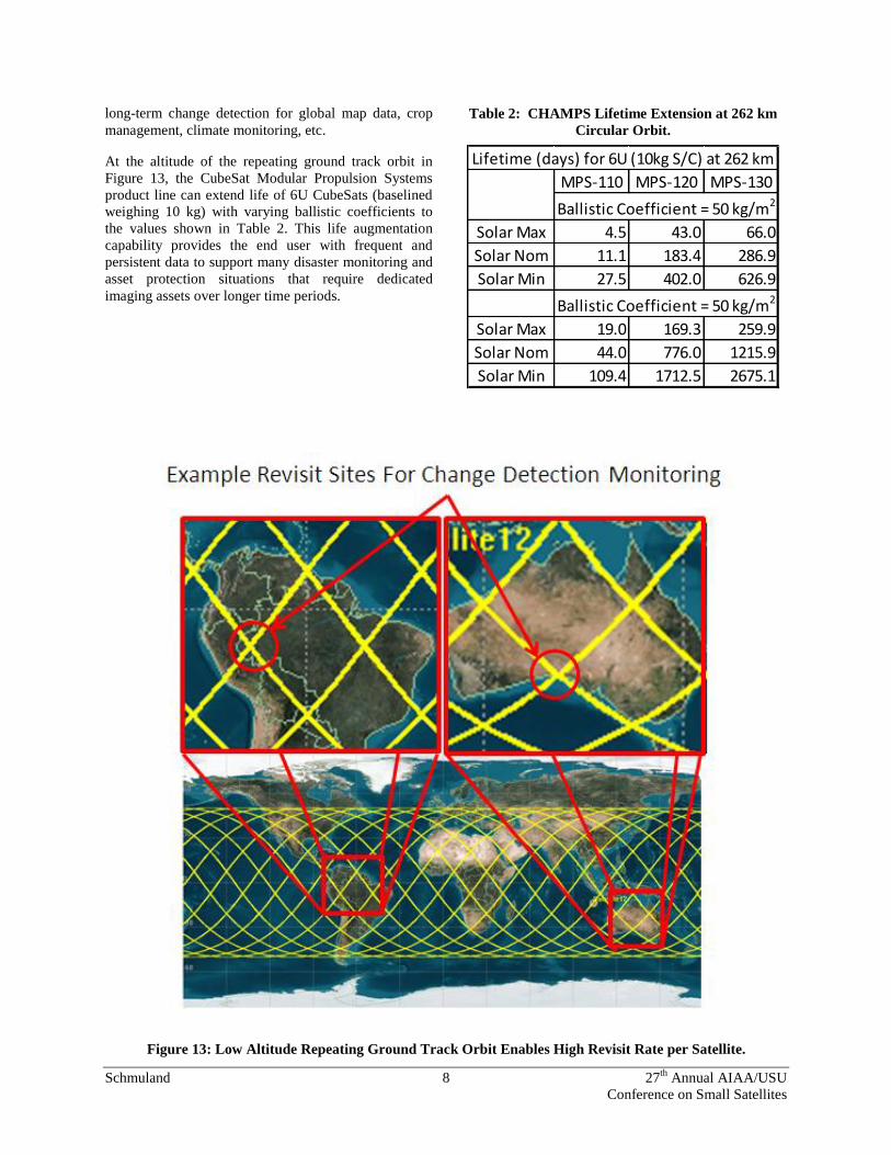
To assure frequent image updates over an area of
interest, a low-altitude, repeating ground track orbit can
be utilized to provide up to two revisits per day per
satellite. Figure 13 below shows such an orbit at 262
km circular, which can provide up to 1.7 m resolution
with a COTS type optical system that provides a 9 cm
aperture and 1.25 m focal length. Revisit sites over
areas of interest for repeating ground track orbits can be
easily selected by calculating the required orbital
injection site and inclination of the launch vehicle, with
the satellite propulsion system conducting the final
orbit “cleanup” burns. Image acquisition over multiple
areas of interest can potentially be achieved with this
system, as Figure 13 demonstrates, to support short and
MPS-110 MPS-120 MPS-130Figure 12: MPS Product Line Mass Dispersal Capability at 5 m/sec ΔV.
Schmuland 8 27th
Annual AIAA/USU
Conference on Small Satellites
long-term change detection for global map data, crop
management, climate monitoring, etc.
At the altitude of the repeating ground track orbit in
Figure 13, the CubeSat Modular Propulsion Systems
product line can extend life of 6U CubeSats (baselined
weighing 10 kg) with varying ballistic coefficients to
the values shown in Table 2. This life augmentation
capability provides the end user with frequent and
persistent data to support many disaster monitoring and
asset protection situations that require dedicated
imaging assets over longer time periods.
Table 2: CHAMPS Lifetime Extension at 262 km
Circular Orbit.
MPS-110 MPS-120 MPS-130
Solar Max 4.5 43.0 66.0
Solar Nom 11.1 183.4 286.9
Solar Min 27.5 402.0 626.9
Solar Max 19.0 169.3 259.9
Solar Nom 44.0 776.0 1215.9
Solar Min 109.4 1712.5 2675.1
Ballistic Coefficient = 50 kg/m2
Ballistic Coefficient = 50 kg/m2
Lifetime (days) for 6U (10kg S/C) at 262 km
Figure 13: Low Altitude Repeating Ground Track Orbit Enables High Revisit Rate per Satellite.
Schmuland 9 27th
Annual AIAA/USU
Conference on Small Satellites
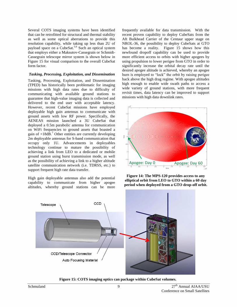
Several COTS imaging systems have been identified
that can be retrofitted for structural and thermal stability
as well as some optical aberrations to provide this
resolution capability, while taking up less than 2U of
payload space on a CubeSat.5,6
Such an optical system
that employs either a Maksutov-Cassegrain or Schmidt-
Cassegrain telescope mirror system is shown below in
Figure 15 for visual comparison to the overall CubeSat
form factor.
Tasking, Processing, Exploitation, and Dissemination
Tasking, Processing, Exploitation, and Dissemination
(TPED) has historically been problematic for imaging
missions with high data rates due to difficulty of
communicating with available ground stations to
guarantee that high-value imaging data is collected and
delivered to the end user with acceptable latency.
However, recent CubeSat missions have employed
deployable high gain antennas to communicate with
ground assets with low RF power. Specifically, the
AENEAS mission launched a 3U CubeSat that
deployed a 0.5m parabolic antenna for communication
on WiFi frequencies to ground assets that boasted a
gain of +18dB.7 Other entities are currently developing
2m deployable antennas for S-band communication that
occupy only 1U. Advancements in deployables
technology continue to mature the possibility of
achieving a link from LEO to a dedicated or mobile
ground station using burst transmission mode, as well
as the possibility of achieving a link to a higher altitude
satellite communication network (i.e. TDRSS, etc.) to
support frequent high rate data transfer.
High gain deployable antennas also add the potential
capability to communicate from higher apogee
altitudes, whereby ground stations can be more
frequently available for data transmission. With the
recent proven capability to deploy CubeSats from the
Aft Bulkhead Carrier of the Centaur upper stage on
NROL-36, the possibility to deploy CubeSats at GTO
has become a reality. Figure 15 shows how this
newfound dropoff capability can be used to provide
more efficient access to orbits with higher apogees by
using propulsion to lower perigee from GTO in order to
significantly increase the orbital decay rate until the
desired apogee altitude is achieved, whereby an apogee
burn is employed to “lock” the orbit by raising perigee
back above the high drag regime. With apogee altitudes
high enough to enable wide swath paths to access a
wide variety of ground stations, with more frequent
revisit times, data latency can be improved to support
missions with high data downlink rates.
Apogee: Day 0 Apogee: Day 60
Figure 14: The MPS-120 provides access to any
elliptical orbit from LEO to GTO within a 60 day
period when deployed from a GTO drop-off orbit.
Figure 15: COTS imaging optics can package within CubeSat volumes.
Schmuland 10 27th
Annual AIAA/USU
Conference on Small Satellites
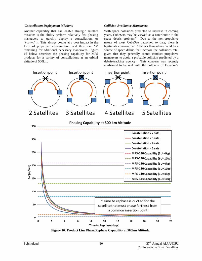
Constellation Deployment Missions
Another capability that can enable strategic satellite
missions is the ability perform relatively fast phasing
maneuvers to quickly deploy a constellation, or
“scatter” it. This always comes at a cost impact in the
form of propellant consumption, and thus less ΔV
remaining for additional necessary maneuvers. Figure
16 below describes the phasing capability for MPS
products for a variety of constellations at an orbital
altitude of 500km.
Collision Avoidance Maneuvers
With space collisions predicted to increase in coming
years, CubeSats may be viewed as a contributor to the
space debris problem.8 Due to the non-propulsive
nature of most CubeSats launched to date, there is
legitimate concern that CubeSats themselves could be a
source of space debris that increase the collisions rate,
given that they generally cannot conduct propulsive
maneuvers to avoid a probable collision predicted by a
debris-tracking agency. This concern was recently
confirmed to be real with the collision of Ecuador’s
0
50
100
150
200
250
300
350
0 2 4 6 8 10 12 14 16 18 20
ΔV
(m/s
ec)
Time to Rephase (days)
Phasing Capability at 500 km Altitude
Constellation = 2 sats
Constellation = 3 sats
Constellation = 4 sats
Constellation = 5 sats
MRS-143 Capability (3U=4kg)
MRS-143 Capability (6U=10kg)
MRS-142 Capability (3U=4kg)
MRS-142 Capability (6U=10kg)
MRS-141 Capability (3U=4kg)
MRS-141 Capability (6U=10kg)
* Time to rephase is quoted for the satellite that must phase farthest from
a common insertion point
Insertion point
2 Satellites
Insertion point
3 Satellites
Insertion point
4 Satellites
Insertion point
5 Satellites
MPS-110
MPS-120
MPS-110
MPS-120
MPS-130
MPS-130
Figure 16: Product Line Phase/Rephase Capability at 500km Altitude.
Schmuland 11 27th
Annual AIAA/USU
Conference on Small Satellites
first CubeSat Pegasus, which is believed to have
collided with debris from a Soviet rocket.9 The MPS-
120 provides the solution to this problem by providing
the impulse required to avoid probable collisions as
well as immediate end-of-life deorbit capability for
CubeSats. The result of this is double-edged; it allows
CubeSat mission architects to plan missions at higher
altitudes, where normally the 25 year deorbit
requirement would not be met, and it alleviates the
concern from organizations operating high-value
spacecraft of unintentional collisions non-maneuverable
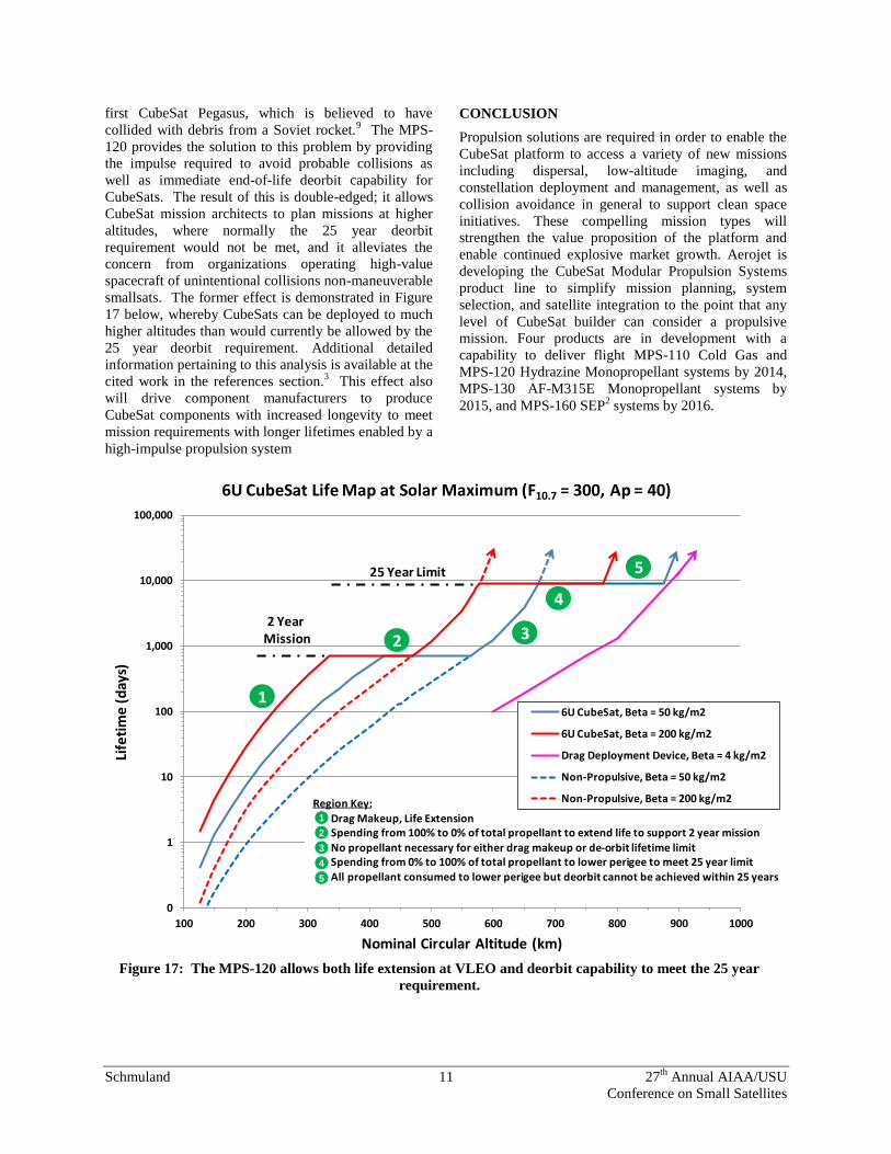
smallsats. The former effect is demonstrated in Figure
17 below, whereby CubeSats can be deployed to much
higher altitudes than would currently be allowed by the
25 year deorbit requirement. Additional detailed
information pertaining to this analysis is available at the
cited work in the references section.3 This effect also
will drive component manufacturers to produce
CubeSat components with increased longevity to meet
mission requirements with longer lifetimes enabled by a
high-impulse propulsion system
CONCLUSION
Propulsion solutions are required in order to enable the
CubeSat platform to access a variety of new missions
including dispersal, low-altitude imaging, and
constellation deployment and management, as well as
collision avoidance in general to support clean space
initiatives. These compelling mission types will
strengthen the value proposition of the platform and
enable continued explosive market growth. Aerojet is
developing the CubeSat Modular Propulsion Systems
product line to simplify mission planning, system
selection, and satellite integration to the point that any
level of CubeSat builder can consider a propulsive
mission. Four products are in development with a
capability to deliver flight MPS-110 Cold Gas and
MPS-120 Hydrazine Monopropellant systems by 2014,
MPS-130 AF-M315E Monopropellant systems by
2015, and MPS-160 SEP2 systems by 2016.
0
1
10
100
1,000
10,000
100,000
100 200 300 400 500 600 700 800 900 1000
Life
tim
e (
day
s)
Nominal Circular Altitude (km)
6U CubeSat Life Map at Solar Maximum (F10.7 = 300, Ap = 40)
6U CubeSat, Beta = 50 kg/m2
6U CubeSat, Beta = 200 kg/m2
Drag Deployment Device, Beta = 4 kg/m2
Non-Propulsive, Beta = 50 kg/m2
Non-Propulsive, Beta = 200 kg/m2Region Key:Drag Makeup, Life ExtensionSpending from 100% to 0% of total propellant to extend life to support 2 year missionNo propellant necessary for either drag makeup or de-orbit lifetime limitSpending from 0% to 100% of total propellant to lower perigee to meet 25 year limitAll propellant consumed to lower perigee but deorbit cannot be achieved within 25 years
1
2 3
4
525 Year Limit
2 Year Mission
1
2
3
4
5
Figure 17: The MPS-120 allows both life extension at VLEO and deorbit capability to meet the 25 year
requirement.
Schmuland 12 27th
Annual AIAA/USU
Conference on Small Satellites
Acknowledgments
The authors would like to acknowledge and thank
Kevin Case and John Erickson of the Vandenberg AFB
Range Safety group for the invaluable technical
assistance they provided the team during this
development effort.
References
1. Zwack, M, et. Al. 2010 “Small Satellite
Capability Analysis: A Systems Approach for
Defining Translational Performance in Small
Satellites,” Proceedings of the AIAA/USU
Conference on Small Satellites, Spacecraft
Systems, Paper No. SSC10-VII-10,
http://digitalcommons.usu.edu/smallsat/2010/all2
010/42/
2. Schmuland, D. T., et. al. 2011 “Hydrazine
Propulsion Module for CubeSats,” Proceedings
of the AIAA/USU Conference on Small Satellites,
Mission Enabling Technologies, Paper No.
SSC11-X-4,
http://digitalcommons.usu.edu/smallsat/2011/all2
011/69/
3. Schmuland, D. T., et. al., “Mission Applications
of the MRS-142 CubeSat High-Impulse
Adaptable Monopropellant Propulsion System
(CHAMPS),” AIAA Paper No. 2012-4269, 48th
AIAA/ASME/SAE/ASEE Joint Propulsion
Conference & Exhibit 30 July - 01 August 2012,
Atlanta, Georgia.
4. Hoskins, A. W., et. al., “Direct Drive Hall
Thruster System Development,” AIAA Paper
2003-4726, 39th AIAA/ASME/SAE/ASEE Joint
Propulsion Conference and Exhibit 20-23 July
2003, Huntsville, Alabama.
5. Blocker, A., et. al. 2008 “TINYSCOPE – The
Feasibility of a 3-Axis Stabilized Earth Imaging
CubeSat from LEO,” Proceedings of the
AIAA/USU Conference on Small Satellites,
Thinking Outside the Box, Paper No. SSC08-X-
4,
http://digitalcommons.usu.edu/smallsat/2008/all2
008/64/
6. Bernhardt, M., et. al. 2009 “RTICC Rapid
Terrestrial Imaging CubeSat Constellation,”,
http://www.agi.com/downloads/partners/edu/UW
_PDR_2009_paper.pdf
7. Aherne, M., et. al. 2011 “Aeneas – Colony I
Meets Three-Axis Pointing,” Proceedings of the
AIAA/USU Conference on Small Satellites, The
Next Generation, Paper No. SSC11-XII-7,
http://digitalcommons.usu.edu/smallsat/2011/all2
011/85/
8. Amos, J., "Space Debris Collisions Expected To
Rise," BBC News, April 22, 2013.
[http://www.bbc.co.uk/news/science-
environment-22253966. Accessed 6/2/13.]
9. Caselli, I., "Ecuador Pegasus Satellite Fears Over
Space Debris Crash," BBC News, May 23, 2013.
[http://www.bbc.co.uk/news/world-latin-america-
22635671. Accessed 6/2/13.]