network traffic characteristics of data centers in the wild
TRANSCRIPT

Network Traffic Characteristics of Data Centers in the Wild
Theophilus Benson∗, Aditya Akella∗ and David A. Maltz†
∗University of Wisconsin–Madison†Microsoft Research–Redmond
ABSTRACT
Although there is tremendous interest in designing improved net-works for data centers, very little is known about the network-leveltraffic characteristics of current data centers. In this paper, we con-duct an empirical study of the network traffic in 10 data centersbelonging to three different types of organizations, including uni-versity, enterprise, and cloud data centers. Our definition of clouddata centers includes not only data centers employed by large on-line service providers offering Internet-facing applications, but alsodata centers used to host data-intensive (MapReduce style) appli-cations. We collect and analyze SNMP statistics, topology, andpacket-level traces. We examine the range of applications deployedin these data centers and their placement, the flow-level and packet-level transmission properties of these applications, and their im-pact on network utilization, link utilization, congestion, and packetdrops. We describe the implications of the observed traffic patternsfor data center internal traffic engineering as well as for recently-proposed architectures for data center networks.
Categories and Subject Descriptors
C.4 [Performance of Systems]: Design studies; Performanceattributes
General Terms
Design, Measurement, Performance
Keywords
Data center traffic, characterization
1. INTRODUCTIONA data center (DC) refers to any large, dedicated cluster of com-
puters that is owned and operated by a single organization. Datacenters of various sizes are being built and employed for a di-verse set of purposes today. On the one hand, large universitiesand private enterprises are increasingly consolidating their IT ser-vices within on-site data centers containing a few hundred to a few
Permission to make digital or hard copies of all or part of this work forpersonal or classroom use is granted without fee provided that copies arenot made or distributed for profit or commercial advantage and that copiesbear this notice and the full citation on the first page. To copy otherwise, torepublish, to post on servers or to redistribute to lists, requires prior specificpermission and/or a fee.IMC’10, November 1–3, 2010, Melbourne, Australia.Copyright 2010 ACM 978-1-4503-0057-5/10/11 ...$10.00.
thousand servers. On the other hand, large online service providers,such as Google, Microsoft, and Amazon, are rapidly building geo-graphically diverse cloud data centers, often containing more than10K servers, to offer a variety of cloud-based services such as E-mail, Web servers, storage, search, gaming, and Instant Messaging.These service providers also employ some of their data centers torun large-scale data-intensive tasks, such as indexing Web pages oranalyzing large data-sets, often using variations of the MapReduceparadigm [6].Despite the growing applicability of data centers in a wide vari-
ety of scenarios, there are very few systematic measurement stud-ies [19, 3] of data center usage to guide practical issues in datacenter operations. Crucially, little is known about the key differ-ences between different classes of data centers, specifically univer-sity campus data centers, private enterprise data centers, and clouddata centers (both those used for customer-facing applications andthose used for large-scale data-intensives tasks).While several aspects of data centers still need substantial em-
pirical analysis, the specific focus of our work is on issues pertain-ing to a data center network’s operation. We examine the send-ing/receiving patterns of applications running in data centers andthe resulting link-level and network-level performance. A betterunderstanding of these issues can lead to a variety of advancements,including traffic engineering mechanisms tailored to improve avail-able capacity and reduce loss rates within data centers, mechanismsfor improved quality-of-service, and even techniques for managingother crucial data center resources, such as energy consumption.Unfortunately, the few recent empirical studies [19, 3] of data cen-ter networks are quite limited in their scope, making their observa-tions difficult to generalize and employ in practice.In this paper, we study data collected from ten data centers to
shed light on their network design and usage and to identify prop-erties that can help improve operation of their networking sub-strate. The data centers we study include three university campusdata centers, two private enterprise data centers, and five cloud
data centers, three of which run a variety of Internet-facing ap-plications while the remaining two predominantly run MapReduceworkloads. Some of the data centers we study have been in op-eration for over 10 years, while others were commissioned muchmore recently. Our data includes SNMP link statistics for all datacenters, fine-grained packet traces from select switches in four ofthe data centers, and detailed topology for five data centers. Bystudying different classes of data centers, we are able to shed lighton the question of how similar or different they are in terms of theirnetwork usage, whether results taken from one class can be appliedto the others, and whether different solutions will be needed fordesigning and managing the data centers’ internal networks.We perform a top-down analysis of the data centers, starting with

the applications run in each data center and then drilling down tothe applications’ send and receive patterns and their network-levelimpact. Using packet traces, we first examine the type of appli-cations running in each data center and their relative contributionto network traffic. We then examine the fine-grained sending pat-terns as captured by data transmission behavior at the packet andflow levels. We examine these patterns both in aggregate and at aper-application level. Finally, we use SNMP traces to examine thenetwork-level impact in terms of link utilization, congestion, andpacket drops, and the dependence of these properties on the loca-tion of the links in the network topology and on the time of day.Our key empirical findings are the following:
• We see a wide variety of applications across the data centers,ranging from customer-facing applications, such as Web ser-vices, file stores, authentication services, Line-of-Businessapplications, and custom enterprise applications to data in-tensive applications, such as MapReduce and search index-ing. We find that application placement is non-uniform acrossracks.
• Most flows in the data centers are small in size (≤ 10KB),a significant fraction of which last under a few hundreds ofmilliseconds, and the number of active flows per second isunder 10,000 per rack across all data centers.
• Despite the differences in the size and usage of the data cen-ters, traffic originating from a rack in a data center is ON/OFFin nature with properties that fit heavy-tailed distributions.
• In the cloud data centers, a majority of traffic originated byservers (80%) stays within the rack. For the university andprivate enterprise data centers, most of the traffic (40-90%)leaves the rack and traverses the network’s interconnect.
• Irrespective of the type, in most data centers, link utilizationsare rather low in all layers but the core. In the core, we findthat a subset of the core links often experience high utiliza-tion. Furthermore, the exact number of highly utilized corelinks varies over time, but never exceeds 25% of the corelinks in any data center.
• Losses occur within the data centers; however, losses are notlocalized to links with persistently high utilization. Instead,losses occur at links with low average utilization implicat-ing momentary spikes as the primary cause of losses. Weobserve that the magnitude of losses is greater at the aggre-gation layer than at the edge or the core layers.
• We observe that link utilizations are subject to time-of-dayand day-of-week effects across all data centers. However inmany of the cloud data centers, the variations are nearly anorder of magnitude more pronounced at core links than atedge and aggregation links.
To highlight the implications of our observations, we concludethe paper with an analysis of two data center network design issuesthat have received a lot of recent attention, namely, network bisec-tion bandwidth and the use of centralized management techniques.
• Bisection Bandwidth: Recent data center network proposalshave argued that data centers need high bisection bandwidthto support demanding applications. Our measurements showthat only a fraction of the existing bisection capacity is likelyto be utilized within a given time interval in all the data cen-ters, even in the “worst case” where application instances are
Data Center Type of Type of # of DCs
Study Data Center Apps Measured
Fat-tree [1] Cloud MapReduce 0
Hedera [2] Cloud MapReduce 0
Portland [22] Cloud MapReduce 0
BCube [13] Cloud MapReduce 0
DCell [16] Cloud MapReduce 0
VAL2 [11] Cloud MapReduce 1
Micro TE [4] Cloud MapReduce 1
Flyways [18] Cloud MapReduce 1
Optical switching [29] Cloud MapReduce 1
ECMP. study 1 [19] Cloud MapReduce 1
ECMP. study 2 [3] Cloud MapReduce 19Web Services
Elastic Tree [14] ANY Web Services 1
SPAIN [21] Any Any 0
Our work Cloud MapReduce 10Private Net WebservicesUniversities Distributed F’S
Table 1: Comparison of prior data center studies, including
type of data center and application.
spread across racks rather than confined within a rack. Thisis true even for MapReduce data centers that see relativelyhigher utilization. From this, we conclude that load balanc-ing mechanisms for spreading traffic across the existing linksin the network’s core can help manage occasional conges-tion, given the current applications used.
• Centralization Management: A few recent proposals [2,14] have argued for centrally managing and scheduling network-wide transmissions to more effectively engineer data centertraffic. Our measurements show that centralized approachesmust employ parallelism and fast route computation heuris-tics to scale to the size of data centers today while supportingthe application traffic patterns we observe in the data centers.
The rest of the paper is structured as follows: we present relatedwork in Section 2 and in Section 3 describe the data centers studied,their high-level design, and typical uses. In Section 4, we describethe applications running in these data centers. In Section 5, wezoom into the microscopic properties of the various data centers.In Section 6, we examine the flow of traffic within data centers andthe utilization of links across the various layers. We discuss the im-plications of our empirical insights in Section 7, and we summarizeour findings in Section 8.
2. RELATED WORKThere is tremendous interest in designing improved networks for
data centers [1, 2, 22, 13, 16, 11, 4, 18, 29, 14, 21]; however, suchwork and its evaluation is driven by only a few studies of data cen-ter traffic, and those studies are solely of huge (> 10K server) datacenters, primarily running data mining, MapReduce jobs, or Webservices. Table 1 summarizes the prior studies. From Table 1, weobserve that many of the data architectures are evaluated withoutempirical data from data centers. For the architectures evaluatedwith empirical data, we find that these evaluations are performedwith traces from cloud data centers. These observations imply thatthe actual performance of these techniques under various types ofrealistic data centers found in the wild (such as enterprise and uni-versity data centers) is unknown and thus we are motivated by thisto conduct a broad study on the characteristics of data centers. Sucha study will inform the design and evaluation of current and futuredata center techniques.

This paper analyzes the network traffic of the broadest set ofdata centers studied to date, including data centers running Webservices and MapReduce applications, but also other common en-terprise and campus data centers that provide file storage, authen-tication services, Line-of-Business applications, and other custom-written services. Thus, our work provides the information neededto evaluate data center network architecture proposals under thebroad range of data center environments that exist.Previous studies [19, 3] have focused on traffic patterns at coarse
time-scales, reporting flow size distributions, number of concurrentconnections, duration of congestion periods, and diurnal patterns.We extend these measures by considering additional issues, such asthe applications employed in the different data centers, their trans-mission patterns at the packet and flow levels, their impact on linkand network utilizations, and the prevalence of network hot-spots.This additional information is crucial to evaluating traffic engineer-ing strategies and data center placement/scheduling proposals.The closest prior works are [19] and [3]; the former focuses
on a single MapReduce data centers, while the latter considerscloud data centers that host Web services as well as those runningMapReduce. Neither study considers non-cloud data centers, suchas enterprise and campus data centers, and neither provides as com-plete a picture of traffic patterns as this study. The key observationsfrom Benson’s study [3] are that utilizations are highest in the corebut losses are highest at the edge. In our work, we augment thesefindings by examining the variations in link utilizations over time,the localization of losses to link, and the magnitude of losses overtime. From Kandula’s study [19], we learned that while most trafficin the cloud is restricted to within a rack and a significant numberof hot-spots exist in the network. Our work supplements these re-sults by quantifying the exact fraction of traffic that stays withina rack for a wide range of data centers. In addition, we quantifythe number of hot-spots, show that losses are due to the underly-ing burstiness of traffic, and examine the flow level properties foruniversity and private enterprise (both are classes of data centersignored in Kandula’s study [19]).Our work complements prior work on measuring Internet traf-
fic [20, 10, 25, 9, 8, 17] by presenting an equivalent study on theflow characteristics of applications and link utilizations within datacenters. We find that data center traffic is statistically different fromwide area traffic, and that such behavior has serious implicationsfor the design and implementation of techniques for data centernetworks.
3. DATASETS AND OVERVIEW OF DATA
CENTERSIn this paper, we analyze data-sets from 10 data centers, includ-
ing 5 commercial cloud data centers, 2 private enterprise data cen-ters, and 3 university campus data centers. For each of these datacenters, we examine one or more of the following data-sets: net-work topology, packet traces from select switches, and SNMP pollsfrom the interfaces of network switches. Table 2 summarizes thedata collected from each data center, as well as some key proper-ties.Table 2 shows that the data centers vary in size, both in terms of
the number of devices and the number of servers. Unsurprisingly,the largest data centers are used for commercial computing needs(all owned by a single entity), with the enterprise and universitydata centers being an order of magnitude smaller in terms of thenumber of devices.The data centers also vary in their proximity to their users. The
enterprise and university data centers are located in the western/mid-
Data Center Name Number of Locations
EDU1 1
EDU2 1
EDU3 1
PRV2 4
Table 3: The number of packet trace collection locations for the
data centers in which we were able to install packet sniffers.
western U.S. and are hosted on the premises of the organizationsto serve local users. In contrast, the commercial data centers aredistributed around the world in the U.S., Europe, and South Amer-ica. Their global placement reflects an inherent requirement forgeo-diversity (reducing latency to users), geo-redundancy (avoid-ing strikes, wars, or fiber cuts in one part of the world), and regu-latory constraints (some data can not be removed from the E.U. orU.S.).In what follows, we first describe the data we collect. We then
outline similarities and differences in key attributes of the data cen-ters, including their usage profiles, and physical topology. Wefound that understanding these aspects is required to analyze theproperties that we wish to measure in subsequent sections, such asapplication behavior and its impact on link-level and network-wideutilizations.
3.1 Data CollectionSNMP polls: For all of the data centers that we studied, we
were able to poll the switches’ SNMP MIBs for bytes-in and bytes-out at granularities ranging from 1 minute to 30 minutes. For the5 commercial cloud data centers and the 2 private enterprises, wewere able to poll for the number of packet discards as well.For each data center, we collected SNMP data for at least 10
days. In some cases (e.g., EDU1, EDU2, EDU3, PRV1, PRV2,CLD1, CLD4), our SNMP data spans multiple weeks. The longtime-span of our SNMP data allows us to observe time-of-day andday-of-week dependencies in network traffic.Network Topology: For the private enterprises and university
data centers, we obtained topology via the Cisco CDP protocol,which gives both the network topology as well as the link capaci-ties. When this data is unavailable, as with the 5 cloud data centers,we analyze device configuration to derive properties of the topol-ogy, such as the relative capacities of links facing endhosts versusnetwork-internal links versus WAN-facing links.Packet traces: Finally, we collected packet traces from a few
of the private enterprise and university data centers (Table 2). Ourpacket trace collection spans 12 hours over multiple days. Since itis difficult to instrument an entire data center, we selected a hand-ful of locations at random per data center and installed sniffers onthem. In Table 3, we present the number of sniffers per data center.In the smaller data centers (EDU1, EDU2, EDU3), we installed1 sniffer. For the larger data center (PRV2), we installed 4 snif-fers. All traces were captured using a Cisco port span. To accountfor delay introduced by the packet duplication mechanism and forendhost clock skew, we binned results from the spans into 10 mi-crosecond bins.
3.2 High-level Usage of the Data CentersIn this section, we outline important high-level similarities and
differences among the data centers we studied.University data centers: These data centers serve the students
and administrative staff of the university in question. They pro-vide a variety of services, ranging from system back-ups to hostingdistributed file systems, E-mail servers, Web services (administra-

Data Center Data Center Location Age (Years) SNMP Packet Topology Number Number Over
Role Name (Curr Ver/Total) Traces Devices Servers Subscription
Universities
EDU1 US-Mid 10 X X X 22 500 2:1EDU2 US-Mid (7/20) X X X 36 1093 47:1EDU3 US-Mid N/A X X X 1 147 147:1
PrivatePRV1 US-Mid (5/5) X X X 96 1088 8:3PRV2 US-West > 5 X X X 100 2000 48:10
Commercial
CLD1 US-West > 5 X X X 562 10K 20:1CLD2 US-West > 5 X X X 763 15K 20:1CLD3 US-East > 5 X X X 612 12K 20:1CLD4 S. America (3/3) X X X 427 10K 20:1CLD5 S. America (3/3) X X X 427 10K 20:1
Table 2: Summary of the 10 data centers studied, including devices, types of information collected, and the number of servers.
tive sites and web portals for students and faculty), and multicastvideo streams. We provide the exact application mix in the nextsection. In talking to the network operators, we found that thesedata centers “organically” evolved over time, moving from a col-lection of devices in a storage closet to a dedicated room for serversand network devices. As the data centers reached capacity, the op-erators re-evaluated their design and architecture. Many operatorschose to move to a more structured, two-layer topology and intro-duced server virtualization to reduce heating and power require-ments while controlling data center size.Private enterprises: The private enterprise IT data centers serve
corporate users, developers, and a small number of customers. Un-like university data centers, the private enterprise data centers sup-port a significant number of custom applications, in addition tohosting traditional services like Email, storage, and Web services.They often act as development testbeds, as well. These data cen-ters are developed in a ground-up fashion, being designed specif-ically to support the demands of the enterprise. For instance, tosatisfy the need to support administrative services and beta testingof database-dependent products, PRV1 commissioned the develop-ment of an in-house data center 5 years ago. PRV2 was designedover 5 years ago mostly to support custom Line-of-Business appli-cations and to provide login servers for remote users.Commercial cloud data centers: Unlike the first two classes
of data centers, the commercial data centers cater to external usersand offer support for a wide range of Internet-facing services, in-cluding: Instant Messaging, Webmail, search, indexing, and video.Additionally, the data centers host large internal systems that sup-port the externally visible services, for example data mining, stor-age, and relational databases (e.g., for buddy lists). These data cen-ters are often purpose-built to support a specific set of applications(e.g., with a particular topology or over-subscription ratio to sometarget application patterns), but there is also a tension to make themas general as possible so that the application mix can change overtime as the usage evolves. CLD1, CLD2, CLD3 host a variety ofapplications, ranging from Instant Messaging and Webmail to ad-vertisements and web portals. CLD4 and CLD5 are primarily usedfor running MapReduce style applications.
3.3 Topology andComposition of the Data Cen-ters
In this section, we examine the differences and similarities inthe physical construction of the data centers. Before proceedingto examine the physical topology of the data centers studied, wepresent a brief overview of the topology of a generic data center. InFigure 1, we present a canonical 3-Tiered data center. The 3 tiers ofthe data center are the edge tier, which consists of the Top-of-Rackswitches that connect the servers to the data center’s network fabric;the aggregation tier, which consists of devices that interconnect the
Figure 1: Canonical 3-Tier data center topology.
ToR switches in the edge layer; and the core tier, which consistsof devices that connect the data center to the WAN. In smaller datacenters, the core tier and the aggregation tier are collapsed into onetier, resulting in a 2-Tiered data center topology.Now, we focus on topological structure and the key physical
properties of the constituent devices and links. We find that thetopology of the data center is often an accident of history. Somehave regular patterns that could be leveraged for traffic engineer-ing strategies like Valiant Load Balancing [11], while most wouldrequire either a significant upgrade or more general strategies.
Topology. Of the three university data centers, we find that two(EDU1, EDU2) have evolved into a structured 2-Tier architecture.The third (EDU3) uses a star-like topology with a high-capacitycentral switch interconnecting a collection of server racks – a de-sign that has been used since the inception of this data center. Asof this writing, the data center was migrating to a more structuredset-up similar to the other two.EDU1 uses a topology that is similar to a canonical 2-Tier ar-
chitecture, with one key difference: while the canonical 2-Tier datacenters use Top-of-Rack switches, where each switch connects to arack of 20-80 servers or so, these two data centers utilize Middle-of-Rack switches that connect a row of 5 to 6 racks with the po-tential to connect from 120 to 180 servers. We find that similarconclusions hold for EDU2 (omitted for brevity).The enterprise data centers do not deviate much from textbook-
style constructions. In particular, the PRV1 enterprise data centerutilizes a canonical 2-Tier Cisco architecture. The PRV2 data cen-ter utilizes a canonical 3-Tier Cisco architecture.

0
20
40
60
80
100
PRV21 PRV22 PRV23 PRV24 EDU1 EDU2 EDU3
Perc
ent of B
yte
s P
er
App
Data Center Edge Switches
OTHERHTTP
HTTPSLDAP
SMBNCP
AFS
Figure 2: Classification of network traffic to application using
Bro-Id. Each of the sniffers sees a very different mix of appli-
cations, even though the first 4 sniffers are located on different
switches in the same data center.
Note that we do not have the physical topologies from the clouddata centers, although the operators of these data centers tell us thatthese networks uniformly employ the 3-Tier textbook data centerarchitectures described in [11].
4. APPLICATIONS IN DATA CENTERSWe begin our “top-down” analysis of data centers by first focus-
ing on the applications they run. In particular, we aim to answerthe following questions: (1) What type of applications are runningwithin these data centers? and, (2) What fraction of traffic origi-nated by a switch is contributed by each application?We employ packet trace data in this analysis and use Bro-Id [26]
to perform application classification. Recall that we collected packettrace data for 7 switches spanning 4 data centers, namely, the uni-versity campus data centers, EDU1, EDU2, and EDU3, and a pri-vate enterprise data center, PRV2. To lend further weight to ourobservations, we spoke to the operators of each data center, includ-ing the 6 for which we did not have packet trace data. The operatorsprovided us with additional information about the specific applica-tions running in their data centers.The type of applications found at each edge switch, along with
their relative traffic volumes, are shown in Figure 2. Each bar corre-sponds to a sniffer in a data center, and the first 4 bars are from the 4edges switches within the same data center (PRV2). In conversingwith the operators, we discovered that this data center hosts a mix-ture of authentication services (labeled “LDAP”), 3-Tier Line-Of-Business Web applications (captured in “HTTP” and “HTTPS”),and custom home-brewed applications (captured in “Others”).By looking at the composition of the 4 bars for PRV2, we can in-
fer how the services and applications are deployed across racks inthe data center. We find that each of the edge switches monitoredhosts a portion of the back-end for the custom applications (cap-tured in “Others”). In particular, the rack corresponding to PRV24appears to predominantly host custom applications that contributeover 90% of the traffic from this switch. At the other switches,these applications make up 50%, 25%, and 10% of the bytes, re-spectively.Further, we find that the secure portions of the Line-of-Business
Web services (labeled “HTTPS”) are hosted in the rack correspond-
ing to the edge switch PRV22, but not in the other three racksmonitored. Authentication services (labeled “LDAP”) are deployedacross the racks corresponding to PRV21 and PRV22, which makesup a significant fraction of bytes from these switches (40% of thebytes from PRV21 and 25% of the byes from PRV22). A smallamount of LDAP traffic (2% of all bytes on average) originatesfrom the other two switches, as well, but this is mostly request traf-fic headed for the authentication services in PRV21 and PRV22.Finally, the unsecured portions of the Line-of-Business (consist-
ing of help pages and basic documentation) are located predom-inantly on the rack corresponding to the edge switch PRV23—nearly 85% of the traffic originating from this rack is HTTP.We also see some amount of file-system traffic (SMB) across all
the 4 switches (roughly 4% of the bytes on average).Clustering of application components within this data center leads
us to believe that emerging patterns of virtualization and consol-idations have not yet led to applications being spread across theswitches.Next, we focus on the last 3 bars, which correspond to an edge
switch each in the 3 university data centers, EDU1, EDU2 andEDU3. While these 3 data centers serve the same types of users weobserve variations across the networks. Two of the university datacenters, EDU2 and EDU3, seem to primarily utilize the network fordistributed file systems traffic, namely AFS and NCP—AFSmakesup nearly all the traffic seen at the EDU3 switch, while NCP con-stitutes nearly 80% of the traffic at the EDU2 switch. The trafficat the last data center, EDU1, is split 60/40 between Web services(both HTTP and HTTPS) and other applications such as file sharing(SMB). The operator of this data center tells us that the data centeralso hosts payroll and benefits applications, which are captured in“Others.”Note that we find file system traffic to constitute a more signifi-
cant fraction of the switches in the university data centers we mon-itored compared to the enterprise data center.The key take-aways from the above observations are that (1)
There is a wide variety of applications observed both within andacross data centers, such as “regular” and secure HTTP transac-tions, authentication services, file-system traffic, and custom ap-plications and (2) We observe a wide variation in the compositionof traffic originated by the switches in a given data center (see the4 switches corresponding to PRV2). This implies that one cannotassume that applications are placed uniformly at random in datacenters.For the remaining data centers (i.e., PRV1, CLD1–5), where we
did not have access to packet traces, we used information from op-erators to understand the application mix. CLD4 and CLD5 areutilized for running MapReduce jobs, with each job, scheduled topack as many of its nodes as possible into the same rack to reducedemand on the data center’s core interconnect. In contrast, CLD1,CLD2, and CLD3 host a variety of applications, ranging from mes-saging and Webmail to Web portals. Each of these applications iscomprised of multiple components with intricate dependencies, de-ployed across the entire data center. For example, the Web portalrequires access to an authentication service for verifying users, andit also requires access to a wide range of Web services from whichdata is aggregated. Instant Messaging similarly utilizes an authen-tication service and composes the user’s buddy list by aggregatingdata spread across different data stores. The application mix foundin the data centers impacts the traffic results, which we look at next.
5. APPLICATIONCOMMUNICATIONPAT-
TERNSIn the previous section, we described the set of applications run-
ning in each of the 10 data centers and observed that a variety ofapplications run in the data centers and that their placement is non-uniform. In this section, we analyze the aggregate network trans-mission behavior of the applications, both at the flow-level and atthe finer-grained packet-level. Specifically, we aim to answer thefollowing questions: (1) What are the aggregate characteristics offlow arrivals, sizes, and durations? and (2) What are the aggre-gate characteristics of the packet-level inter-arrival process acrossall applications in a rack — that is, how bursty are the transmis-sion patterns of these applications? These aspects have importantimplications for the performance of the network and its links.As before, we use the packet traces in our analysis.
5.1 Flow-Level Communication Characteris-tics
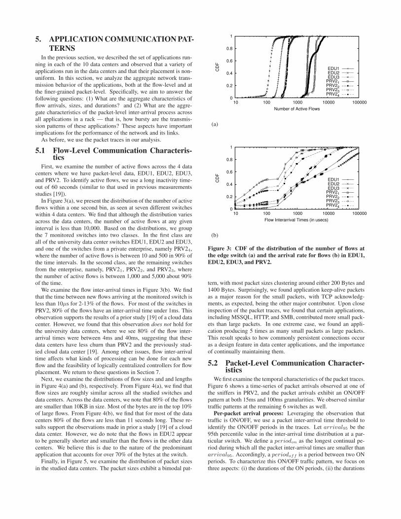
First, we examine the number of active flows across the 4 datacenters where we have packet-level data, EDU1, EDU2, EDU3,and PRV2. To identify active flows, we use a long inactivity time-out of 60 seconds (similar to that used in previous measurementsstudies [19]).In Figure 3(a), we present the distribution of the number of active
flows within a one second bin, as seen at seven different switcheswithin 4 data centers. We find that although the distribution variesacross the data centers, the number of active flows at any giveninterval is less than 10,000. Based on the distributions, we groupthe 7 monitored switches into two classes. In the first class areall of the university data center switches EDU1, EDU2 and EDU3,and one of the switches from a private enterprise, namely PRV24,where the number of active flows is between 10 and 500 in 90% ofthe time intervals. In the second class, are the remaining switchesfrom the enterprise, namely, PRV21, PRV22, and PRV23, wherethe number of active flows is between 1,000 and 5,000 about 90%of the time.We examine the flow inter-arrival times in Figure 3(b). We find
that the time between new flows arriving at the monitored switch isless than 10µs for 2-13% of the flows. For most of the switches inPRV2, 80% of the flows have an inter-arrival time under 1ms. Thisobservation supports the results of a prior study [19] of a cloud datacenter. However, we found that this observation does not hold forthe university data centers, where we see 80% of the flow inter-arrival times were between 4ms and 40ms, suggesting that thesedata centers have less churn than PRV2 and the previously stud-ied cloud data center [19]. Among other issues, flow inter-arrivaltime affects what kinds of processing can be done for each newflow and the feasibility of logically centralized controllers for flowplacement. We return to these questions in Section 7.Next, we examine the distributions of flow sizes and and lengths
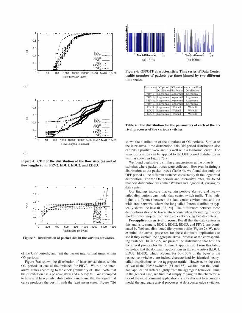
in Figure 4(a) and (b), respectively. From Figure 4(a), we find thatflow sizes are roughly similar across all the studied switches anddata centers. Across the data centers, we note that 80% of the flowsare smaller than 10KB in size. Most of the bytes are in the top 10%of large flows. From Figure 4(b), we find that for most of the datacenters 80% of the flows are less than 11 seconds long. These re-sults support the observations made in prior a study [19] of a clouddata center. However, we do note that the flows in EDU2 appearto be generally shorter and smaller than the flows in the other datacenters. We believe this is due to the nature of the predominantapplication that accounts for over 70% of the bytes at the switch.Finally, in Figure 5, we examine the distribution of packet sizes
in the studied data centers. The packet sizes exhibit a bimodal pat-
(a)
0
0.2
0.4
0.6
0.8
1
10 100 1000 10000 100000
CD
F
Number of Active Flows
EDU1EDU2EDU3
PRV21PRV22PRV23PRV24
(b)
0
0.2
0.4
0.6
0.8
1
10 100 1000 10000 100000C
DF
Flow Interarrival Times (in usecs)
EDU1EDU2EDU3
PRV21PRV22PRV23PRV24
Figure 3: CDF of the distribution of the number of flows at
the edge switch (a) and the arrival rate for flows (b) in EDU1,
EDU2, EDU3, and PRV2.
tern, with most packet sizes clustering around either 200 Bytes and1400 Bytes. Surprisingly, we found application keep-alive packetsas a major reason for the small packets, with TCP acknowledg-ments, as expected, being the other major contributor. Upon closeinspection of the packet traces, we found that certain applications,including MSSQL, HTTP, and SMB, contributed more small pack-ets than large packets. In one extreme case, we found an appli-cation producing 5 times as many small packets as large packets.This result speaks to how commonly persistent connections occuras a design feature in data center applications, and the importanceof continually maintaining them.
5.2 Packet-Level Communication Character-istics
Wefirst examine the temporal characteristics of the packet traces.Figure 6 shows a time-series of packet arrivals observed at one ofthe sniffers in PRV2, and the packet arrivals exhibit an ON/OFFpattern at both 15ms and 100ms granularities. We observed similartraffic patterns at the remaining 6 switches as well.Per-packet arrival process: Leveraging the observation that
traffic is ON/OFF, we use a packet inter-arrival time threshold toidentify the ON/OFF periods in the traces. Let arrival95 be the95th percentile value in the inter-arrival time distribution at a par-ticular switch. We define a periodon as the longest continual pe-riod during which all the packet inter-arrival times are smaller thanarrival95. Accordingly, a periodoff is a period between two ONperiods. To characterize this ON/OFF traffic pattern, we focus onthree aspects: (i) the durations of the ON periods, (ii) the durations
(a)
0
0.2
0.4
0.6
0.8
1
1 10 100 1000 10000 100000 1e+06 1e+07 1e+08
CD
F
Flow Sizes (in Bytes)
EDU1EDU2EDU3
PRV21PRV22PRV23PRV24
(b)
0
0.2
0.4
0.6
0.8
1
1 10 100 1000 10000 100000 1e+06 1e+07 1e+08 1e+09
CD
F
Flow Lengths (in usecs)
EDU1EDU2EDU3
PRV21PRV22PRV23PRV24
Figure 4: CDF of the distribution of the flow sizes (a) and of
flow lengths (b) in PRV2, EDU1, EDU2, and EDU3.
0
0.2
0.4
0.6
0.8
1
0 200 400 600 800 1000 1200 1400 1600
CD
F
Packet Size (in Bytes)
EDU1EDU2EDU3
PRV21PRV22PRV23PRV24
Figure 5: Distribution of packet size in the various networks.
of the OFF periods, and (iii) the packet inter-arrival times withinON periods.Figure 7(a) shows the distribution of inter-arrival times within
ON periods at one of the switches for PRV2. We bin the inter-arrival times according to the clock granularity of 10µs. Note thatthe distribution has a positive skew and a heavy tail. We attemptedto fit several heavy-tailed distributions and found that the lognormalcurve produces the best fit with the least mean error. Figure 7(b)
0 2 4 6 8 10
x 104Time (in Milliseconds)
# o
f p
ackets
receiv
ed
0 2 4 6 8 10
x 104Time (in milliseconds)
# p
ackets
receiv
ed
(a) 15ms (b) 100ms
Figure 6: ON/OFF characteristics: Time series of Data Center
traffic (number of packets per time) binned by two different
time scales.
Data center Off period ON period Interarrival RateDistributionDistribution Distribution
PRV 21 Lognormal Lognormal Lognormal
PRV 22 Lognormal Lognormal Lognormal
PRV 23 Lognormal Lognormal Lognormal
PRV 24 Lognormal Lognormal Lognormal
EDU1 Lognormal Weibull Weibull
EDU2 Lognormal Weibull Weibull
EDU3 Lognormal Weibull Weibull
Table 4: The distribution for the parameters of each of the ar-
rival processes of the various switches.
shows the distribution of the durations of ON periods. Similar tothe inter-arrival time distribution, this ON period distribution alsoexhibits a positive skew and fits well with a lognormal curve. Thesame observation can be applied to the OFF period distribution aswell, as shown in Figure 7(c).We found qualitatively similar characteristics at the other 6
switches where packet traces were collected. However, in fitting adistribution to the packet traces (Table 4), we found that only theOFF period at the different switches consistently fit the lognormaldistribution. For the ON periods and interarrival rates, we foundthat best distribution was either Weibull and lognormal, varying bydata center.Our findings indicate that certain positive skewed and heavy-
tailed distributions can model data center switch traffic. This high-lights a difference between the data center environment and thewide area network, where the long-tailed Pareto distribution typ-ically shows the best fit [27, 24]. The differences between thesedistributions should be taken into account when attempting to applymodels or techniques from wide area networking to data centers.Per-application arrival process: Recall that the data centers in
this analysis, namely, EDU1, EDU2, EDU3, and PRV2, are domi-nated byWeb and distributed file-system traffic (Figure 2). We nowexamine the arrival processes for these dominant applications tosee if they explain the aggregate arrival process at the correspond-ing switches. In Table 5, we present the distribution that best fitsthe arrival process for the dominant application. From this table,we notice that the dominant applications in the universities (EDU1,EDU2, EDU3), which account for 70–100% of the bytes at therespective switches, are indeed characterized by identical heavy-tailed distributions as the aggregate traffic. However, in the caseof two of the PRV2 switches (#1 and #3), we find that the domi-nant application differs slightly from the aggregate behavior. Thus,in the general case, we find that simply relying on the characteris-tics of the most dominant applications is not sufficient to accuratelymodel the aggregate arrival processes at data center edge switches.

Data center Off period Interarrival Rate ON period DominantDistribution Distribution DistributionApplications
PRV 21 Lognormal Weibull Exponential Others
PRV 22 Weibull Lognormal Lognormal LDAP
PRV 23 Weibull Lognormal Exponential HTTP
PRV 24 Lognormal Lognormal Weibull Others
EDU1 Lognormal Lognormal Weibull HTTP
EDU2 Lognormal Weibull Weibull NCP
EDU3 Lognormal Weibull Weibull AFS
Table 5: The distribution for the parameters of each of the ar-
rival processes of the dominant applications on each switch.
(a)10
210
310
4
10−4
10−3
10−2
10−1
100
Interarrival Times (in milliseconds)
CDF
wbl: 0.013792
logn: 0.011119
exp: 0.059716
pareto: 0.027664
data
(b)
20 30 40 50 60 70 80 90 1000
0.1
0.2
0.3
0.4
0.5
0.6
0.7
0.8
0.9
1
Length of ON−Periods (in microseconds)
CDF
wbl :0.016516
logn :0.016093
exp :0.01695
pareto :0.03225
data
(c)
2 3 4 5 6 7 8 9 10
x 104
0.1
0.2
0.3
0.4
0.5
0.6
0.7
0.8
0.9
1
Length of OFF−Periods(in milliseconds)
CDF
wbl: 0.090269
logn: 0.081732
exp: 0.11594
pareto: 0.66908
data
Figure 7: CDF of the distribution of the arrival times of packets
at 3 of the switches in PRV2. The figure contains best fit curve
for lognormal, Weibull, Pareto, and Exponential distributions,
as well as the least mean errors for each.
Finally, we compare the observed distributions for HTTP applica-tions in the data center against HTTP applications in the wide areaand find that the distribution of ON periods in the data center doesmatch observations made by others [7] in the WAN.The take aways from our observations are that: (1) The num-
ber of active flows at a switch in any given second is, at most,10,000 flows. However, new flows can arrive within rapid suc-cession (10µs) of each other, resulting in high instantaneous arrivalrates; (2) Most flows in the data centers we examined are small insize (≤ 10KB) and a significant fraction last under a few hun-dreds of milliseconds; (3) Traffic leaving the edge switches in a
data center is bursty in nature and the ON/OFF intervals can becharacterized by heavy-tailed distributions; and (4) In some datacenters, the predominant application drives the aggregate sendingpattern at the edge switch. In the general case, however, simplyfocusing on dominant applications is insufficient to understand theprocess driving packet transmission into the data center network.In the next section, we analyze link utilizations at the various
layers within the data center to understand how the bursty nature oftraffic impacts the utilization and packet loss of the links at each ofthe layers.
6. NETWORK COMMUNICATION
PATTERNSIn the two previous sections, we examined the applications em-
ployed in each of the 10 data centers, their placement, and trans-mission patterns. In this section, we examine, with the goal ofinforming data center traffic engineering techniques, how existingdata center applications utilize the interconnect. In particular, weaim to answer the following questions: (1) To what extent doesthe current application traffic utilize the data center’s interconnect?For example, is most traffic confined to within a rack or not? (2)What is the utilization of links at different layers in a data center?(3) How often are links heavily utilized and what are the proper-ties of heavily utilized links? For example, how long does heavyutilization persist on these links, and do the highly utilized linksexperience losses? (4) To what extent do link utilizations vary overtime?
6.1 Flow of TrafficWe start by examining the relative proportion of traffic generated
by the servers that stays within a rack (Intra-Rack traffic) versustraffic that leaves its rack for either other racks or external des-tinations (Extra-Rack traffic). Extra-Rack traffic can be directlymeasured, as it is the amount of traffic on the uplinks of the edgeswitches (i.e., the “Top-of-Rack” switches). We compute Intra-Rack traffic as the difference between the volume of traffic gen-erated by the servers attached to each edge switch and the trafficexiting edge switches.In Figure 8, we present a bar graph of the ratio of Extra-Rack to
Intra-Rack traffic in the 10 data centers we studied. We note thata predominant portion of server-generated traffic in the cloud datacenters CLD1–5—nearly, 75% on average—is confined to withinthe rack in which it was generated.Recall from Section 4 that only two of these 5 data centers,
CLD4 and CLD5, run MapReduce style applications, while theother three run amixture of different customer-facingWeb services.Despite this key difference in usage, we observe surprisingly littledifference in the relative proportions of Intra-Rack and Extra-Racktraffic. This can be explained by revisiting the nature of applica-tions in these data centers: as stated in Section 4, the services run-ning in CLD1–3 have dependencies spread across many servers inthe data center. The administrators of these networks try to colo-cate applications and dependent components into the same racks toavoid sharing a rack with other applications/services. Low Extra-Rack traffic is a side-effect of this artifact. In the case of CLD4 andCLD5, the operators assign MapReduce jobs to co-located serversfor similar reasons. However, fault tolerance requires placing re-dundant components of the application and data storage into dif-ferent racks, which increases the Extra-Rack communication. Ourfindings of high Intra-Rack traffic within data centers supports ob-servations made by others [19], where the focus was on cloud datacenters running MapReduce.

0 2
0 4
0 6
0 8
0 1
00
ED
U1
ED
U2
ED
U3
PR
V1
PR
V2
CLD
1
CLD
2
CLD
3
CLD
4
CLD
5
Perc
ent of T
raffic
Data Centers
Intra-Rack Extra-Rack
Figure 8: The ratio of Extra-Rack to Intra-Rack traffic in the
data centers.
Next, we focus on the enterprise and university data centers.With the exception of EDU1, these appear to be both very diffe-rent from the cloud data centers and qualitatively similar to eachother: at least 50% of the server-originated traffic in the data cen-ters leaves the racks, compared with under 25% for the cloud datacenters. These data centers run user-facing applications, such asWeb services and file servers. While this application mix is simi-lar to CLD1–3 discussed above, the Intra/Extra rack usage patternsare quite different. A possible reason for the difference is that theplacement of dependent services in enterprise and campus data cen-ters may not be as optimized as the cloud data centers.
6.2 Link Utilizations vs LayerNext, we examine the impact of the Extra-Rack traffic on the
links within the interconnect of the various data centers. We ex-amine link utilization as a function of location in the data centertopology. Recall that all 10 data centers employed 2-Tiered or 3-Tiered tree-like networks.In performing this study, we studied several hundred 5-minute
intervals at random for each data center and examined the link uti-lizations as reported by SNMP. In Figure 9, we present the utiliza-tion for links across different layers in the data centers for one suchrepresentative interval.In general, we find that utilizations within the core/aggregation
layers are higher than those at the edge; this observation holdsacross all classes of data centers. These findings support observa-tions made by others [3], where the focus was on cloud data centers.A key point to note, not raised by prior work [3], is that across
the various data centers, there are differences in the tail of the dis-tributions for all layers–in some data centers, such as CLD4, thereis a greater prevalence of high utilization links (i.e., utilization 70%or greater) especially in the core layer, while in others there are nohigh utilization links in any layer (e.g., EDU1). Next, we examinethese high utilization links in greater depth.
6.3 Hot-spot LinksIn this section, we study the hot-spot links—those with 70%
or higher utilization—unearthed in various data centers, focusingon the persistence and prevalence of hot-spots. More specifically,we aim to answer the following questions: (1) Do some links fre-quently appear as hot-spots? How does this result vary across lay-ers and data centers? (2) How does the set of hot-spot links ina layer change over time? (3) Do hot-spot links experience highpacket loss?
(a)
0
0.2
0.4
0.6
0.8
1
0.01 0.1 1 10 100
CD
F
Edge Link Utilization
EDU1EDU3PRV1PRV2CLD1CLD2CLD3CLD4CLD5
(b)
0
0.2
0.4
0.6
0.8
1
0.01 0.1 1 10 100
CD
F
Agg Link Utilization
PRV2CLD1CLD2CLD3CLD4CLD5
(c)
0
0.2
0.4
0.6
0.8
1
0.01 0.1 1 10 100
CD
F
Core Link Utilization
EDU1EDU3PRV1PRV2CLD1CLD2CLD3CLD4CLD5
Figure 9: CDF of link utilizations (percentage) in each layer.
6.3.1 Persistence and Prevalence
In Figure 10, we present the distribution of the percentage oftime intervals that a link is a hot-spot. We note from Figures 10(a)and (b) that very few links in either the edge or aggregation lay-ers are hot-spots, and this observations holds across all data centersand data center types. Specifically, only 3% of the links in thesetwo layers appear as a hot-spot for more than 0.1% of time inter-vals. When edge links are congested, they tend to be congestedcontinuously, as in CLD2, where a very small fraction of the edgelinks appear as hot-spots in 90% of the time intervals.In contrast, we find that the data centers differ significantly in
their core layers (Figure 10(c)). Our data centers cluster into 3 hot-spot classes: (1) Low Persistence-Low Prevalence: This class ofdata centers comprises those where the hot-spots are not localizedto any set of links. This includes PRV2, EDU1, EDU2, EDU3,CLD1, and CLD3, where any given core link is a hot-spot for nomore than 10% of the time intervals; (2) High Persistence-LowPrevalence: The second group of data centers is characterized byhot-spots being localized to a small number of core links. This in-cludes PRV1 and CLD2 where 3% and 8% of the core links, respec-tively, each appear as hot-spots in> 50% of the time intervals; and(3) High Persistence-High Prevalence: Finally, in the last groupcontaining CLD4 and CLD5, a significant fraction of the core links

(a)
0.975
0.98
0.985
0.99
0.995
1
0.01 0.1 1 10 100
CD
F
% of Times an Edge Link is a Hotspot
EDU1EDU3PRV1PRV2CLD1CLD2CLD3CLD4CLD5
(b)
0.975
0.98
0.985
0.99
0.995
1
0.01 0.1 1 10 100
CD
F
% of Times an Agg Link is a Hotspot
PRV2CLD1CLD2CLD3CLD4CLD5
(c)
0.65
0.7
0.75
0.8
0.85
0.9
0.95
1
0.1 1 10 100
CD
F
% of Times a Core Link is a Hotspot
EDU1EDU2EDU3PRV1PRV2CLD1CLD2CLD3CLD4CLD5
Figure 10: A CDF of the fraction of times that links in the var-
ious layers are hot-spots.
appear persistently as hot-spots. Specifically, roughly 20% of thecore links are hot-spots at least 50% of the time each. Note thatboth CLD4 and CLD5 run MapReduce applications.Next, we examine the variation in the fraction of the core links
that are hot-spots versus time. In Figure 13, we show our observa-tions for one data center in each of the 3 hot-spot classes just de-scribed. From this figure, we observe that each class has a differentpattern. In the low persistence-low prevalence data center, CLD1,we find that very few hot-spots occur over the course of the day, andwhen they do occur, only a small fraction of the core links emergeas hot-spots (less than 0.002%). However, in the high persistenceclasses, we observe that hot-spots occur throughout the day. In-terestingly, with the high persistence-high prevalence data center,CLD5, we observe that the fraction of links that are hot-spots isaffected by the time of day. Equally important is that only 25% ofthe core links in CLD5 are ever hot-spots. This suggests that, de-pending on the traffic matrix, the remaining 75% of the core linkscan be utilized to offload some traffic from the hot-spot links.
6.3.2 Hot-spots and Discards
Finally, we study loss rates across links in the data centers. In
(a)
0.982
0.984
0.986
0.988
0.99
0.992
0.994
0.996
0.998
1
0.001 0.01 0.1 1 10 100 1000 10000 100000
CD
F
Size of Edge Discards (in Bits)
EDU1EDU3PRV1PRV2CLD1CLD2CLD3CLD4CLD5
(b)
0.9
0.91
0.92
0.93
0.94
0.95
0.96
0.97
0.98
0.99
1
0.001 0.01 0.1 1 10 100 1000 10000 100000 1e+06 1e+07
CD
F
Size of Agg Discards (in Bits)
PRV2CLD1CLD2CLD3CLD4CLD5
(c)
0.93
0.94
0.95
0.96
0.97
0.98
0.99
1
0.001 0.01 0.1 1 10 100 1000 10000
CD
F
Size of Core Discards (in Bits)
EDU1EDU2EDU3PRV1PRV2CLD1CLD2CLD3CLD4CLD5
Figure 11: A CDF of the number of bits lost across the various
layers.
particular, we start by examining the discards for the set of hot-spot links. Surprisingly, we find that none of the hot-spot linksexperience loss. This implies that in the data centers studied, lossdoes not correlate with high utilization.To understand where losses are prevalent, we examine Figures 11
and 12 that display the loss rates and link utilization for the linkswith losses. In the core and aggregation, all the links with losseshave less than 30% average utilization, whereas at the edge, thelinks with losses have nearly 60% utilization. The fact that linkswith relatively low average utilization contain losses indicates thatthese links experience momentary bursts that do not persist for along enough period to increase the average utilization. These mo-mentary bursts can be explained by the bursty nature of the traffic(Section 5).
6.4 Variations in utilizationIn this section, we examine if the utilizations vary over time and
whether or not link utilizations are stable and predictable.We examined the link utilization over a one week period and
found that diurnal patterns exist in all data centers. As an example,Figure 14 presents the utilization for input and output traffic at a

(a)
0.984
0.986
0.988
0.99
0.992
0.994
0.996
0.998
1
0.001 0.01 0.1 1 10 100
CD
F
Utilization of Edge Links with Discards
EDU1EDU3PRV1PRV2CLD1CLD2CLD3CLD4CLD5
(b)
0.91
0.92
0.93
0.94
0.95
0.96
0.97
0.98
0.99
1
0.001 0.01 0.1 1 10 100
CD
F
Utilization of Agg Links with Discards
PRV2CLD1CLD2CLD3CLD4CLD5
(c)
0.93
0.94
0.95
0.96
0.97
0.98
0.99
1
0.001 0.01 0.1 1 10 100
CD
F
Utilization of Core Links with Discards
EDU1EDU2EDU3PRV1PRV2CLD1CLD2CLD3CLD4CLD5
Figure 12: A CDF of the utilization of links with discards.
router port in one of the cloud data centers. The 5-day trace showsdiurnal and pronounced weekend/weekday variations.To quantify this variation, we examine the difference between
peak and trough utilizations for each link across the studied datacenters. In Figure 15, we present the distribution of peak versustrough link utilizations across the various data centers. The x-axisis in percentage. We note that edge links in general show verylittle variation (less than 10% for a least 80% of edge links). Thesame is true for links in the aggregation layer (where available),although we see slightly greater variability. In particular, links inthe aggregation layer of PRV2 show significant variability, whereasthose in the other data centers do not (variation is less than 10% fora least 80% of edge links). Note that links with a low degree ofvariation can be run at a slower speed based on expected trafficvolumes. This could result in savings in network energy costs [14].The variation in link utilizations at the edge/aggregation are sim-
ilar across the studied data centers. At the core, however, we areable to distinguish between several of the data centers. While mosthave low variations (less than 1%), we find that two cloud datacenters (CLD4 and CLD5) have significant variations. Recall thatunlike the other cloud data centers, these two cloud data centers
0
0.001
0.002CLD1
0
0.03
0.06CLD2
0
0.12
0.24
0 50 100 150 200 250 300
Time (in 5 minutes Intervals)
CLD5
Figure 13: Time series of the fraction of links that are hot-spots
in the core layer for CLD1, CLD2, and CLD5.
0
0.02
0.04
0.06
0.08
0.1
0.12
0.14
Firday Saturday Sunday Monday Tuesday
Lin
k U
tiliz
ation
Days of the Week
InOut
Figure 14: Time-of-Day/Day-of-Week traffic patterns.
run primarily MapReduce-style jobs. The large variations reflectdifferences between the periods when data is being reduced fromthe worker nodes to the master and other periods.To summarize, the key take-aways from our analysis of network
traffic patterns are as follows: (1) In cloud data centers, a signifi-cant fraction of traffic stays inside the rack, while the opposite istrue for enterprise and campus data centers; (2) On average, thecore of the data center is the most utilized layer, while the datacenter edge is lightly utilized; (3) The core layers in various datacenters do contain hot-spot links. In some of the data centers, thehot-spots appear only occasionally. In some of the cloud data cen-ters, a significant fraction of core links appear as hot-spots a largefraction of the time. At the same time, the number of core linksthat are hot-spots at any given time is less than 25%; (4) Lossesare not correlated with links with persistently high utilizations. Weobserved losses do occur on links with low average utilization indi-cating that losses are due to momentary bursts; and (5) In general,time-of-day and day-of-week variation exists in many of the datacenters. The variation in link utilization is most significant in thecore of the data centers and quite moderate in other layers of thedata centers.

(a)
0
0.2
0.4
0.6
0.8
1
0.01 0.1 1 10 100
CD
F
Max-Trough for Edge Link
EDU1EDU3PRV1PRV2CLD1CLD2CLD3CLD4CLD5
(b)
0
0.2
0.4
0.6
0.8
1
0.01 0.1 1 10 100
CD
F
Max-Trough for Agg Link
PRV2CLD1CLD2CLD3CLD4CLD5
(c)
0
0.2
0.4
0.6
0.8
1
0.01 0.1 1 10 100
CD
F
Max-Trough for Core Link
EDU1EDU3PRV1PRV2CLD1CLD2CLD3CLD4CLD5
Figure 15: Difference between the peak and trough utilization.
7. IMPLICATIONS FOR DATA CENTER
DESIGN
7.1 Role of Bisection BandwidthSeveral proposals [1, 22, 11, 2] for new data center network ar-
chitectures attempt to maximize the network bisection bandwidth.These approaches, while well suited for data centers, which runapplications that stress the network’s fabric with all-to-all traffic,would be unwarranted in data centers where the bisection band-width is not taxed by the applications. In this section, we re-evaluatethe SNMP and topology data captured from the 10 data centers andexamine whether the prevalent traffic patterns are likely to stress theexisting bisection bandwidth. We also examine how much of theexisting bisection bandwidth is needed at any given time to supportthe prevalent traffic patterns.Before explaining how we address these questions, we provide
a few definitions. We define the bisection links for a tiered datacenter to be the set of links at the top-most tier of the data center’stree architecture; in other words, the core links make up the bisec-tion links. The bisection capacity is the aggregate capacity of theselinks. The full bisection capacity is the capacity that would be re-quired to support servers communicating at full link speeds witharbitrary traffic matrices and no oversubscription. The full bisec-
0 1
0 2
0 3
0
CLD
1
CLD
2
CLD
3
CLD
4
CLD
5
ED
U1
ED
U2
ED
U3
PR
V1
PR
V2
Pre
cent of B
isection U
tiliz
ed
Data Center
CurrentFull
Figure 16: The first bar is the ratio of aggregate server traffic
over Bisection BW and the second bar is the ratio of aggregate
server traffic over full bisection capacity. The y-axis displays
utilization as a percentage.
tion capacity can be computed as simply the aggregate capacity ofthe server NICs.Returning to the questions posed earlier in this section, we use
SNMP data to compute the following: (1) the ratio of the currentaggregate server-generated traffic to the current bisection capacityand (2) the ratio of the current traffic to the full bisection capacity.In doing so, we make the assumption that the bisection links canbe treated as a single pool of capacity from which all offered trafficcan draw. While this may not be true in all current networks, itallows us to determine whether more capacity is needed or ratherbetter use of existing capacity is needed (for example, by improvingrouting, topology, or the migration of application servers inside thedata center).In Figure 16, we present these two ratios for each of the data
centers studied. Recall (from Table 2) that all data centers are over-subscribed, meaning that if all servers sent data as fast as they canand all traffic left the racks, then the bisection links would be fullycongested (we would expect to find utilization ratios over 100%).However, we find in Figure 16 that the prevalent traffic patterns aresuch that, even in the worst case where all server-generated trafficis assumed to leave the rack hosting the server, the aggregate outputfrom servers is smaller than the network’s current bisection capac-ity. This means even if the applications were moved around andthe traffic matrix changed, the current bisection would still be morethan sufficient and no more than 25% of it would be utilized acrossall data centers, including the MapReduce data centers. Finally, wenote that the aggregate output from servers is a negligible fractionof the ideal bisection capacity in all cases. This implies that shouldthese data centers be equipped with a network that provides full bi-section bandwidth, at least 95% of this capacity would go unusedand be wasted by today’s traffic patterns.Thus, the prevalent traffic patterns in the data centers can be sup-
ported by the existing bisection capacity, even if applications wereplaced in such a way that there was more inter-rack traffic thanexists today. This analysis assumes that the aggregate capacity ofthe bisection links forms a shared resource pool from which alloffered traffic can draw. If the topology prevents some offered traf-fic from reaching some links, then some links can experience highutilization while others see low utilization. Even in this situation,however, the issue is one of changing the topology and selectinga routing algorithm that allows offered traffic to draw effectively

from the existing capacity, rather than a question of adding morecapacity. Centralized routing, discussed next, could help in con-structing the requisite network paths.
7.2 Centralized Controllers in Data CentersThe architectures for several proposals [1, 22, 12, 2, 14, 21, 4,
18, 29] rely in some form or another on a centralized controllerfor configuring routes or for disseminating routing information toendhosts. A centralized controller is only practical if it is able toscale up to meet the demands of the traffic characteristics within thedata centers. In this section, we examine this issue in the context ofthe flow properties that we analyzed in Section 5.In particular, we focus on the proposals (Hedera [2], MicroTE [4]
and ElasticTree [14]) that rely on OpenFlow and NOX [15, 23]. Inan OpenFlow architecture, the first packet of a flow, when encoun-tered at a switch, can be forwarded to a central controller that deter-mines the route that the packet should follow in order to meet somenetwork-wide objective. Alternatively, to eliminate the setup delay,the central controller can precompute a set of network paths thatmeet network-wide objectives and install them into the network atstartup time.Our empirical observations in Section 5, have important implica-
tions for such centralized approaches. First, the fact that the numberof active flows is small (see Figure 4(a)) implies that switches en-abled with OpenFlow can make do with a small flow table, whichis a constrained resource on switches today.Second, flow inter-arrival times have important implications for
the scalability of the controller. As we observed in Section 5, a sig-nificant number of new flows (2–20%) can arrive at a given switchwithin 10µs of each other. The switch must forward the first pack-ets of these flows to the controller for processing. Even if the datacenter has as few as a 100 edge switches, in the worst case, a con-troller can see 10 new flows per µs or 10 million flows per sec-ond. Depending on the complexity of the objective implemented atthe controller, computing a route for each of these flows could beexpensive. For example, prior work [5] showed a commodity ma-chine computing a simple shortest path for only 50K flow arrivalsper second. Thus, to scale the throughput of a centralized con-trol framework while supporting complex routing objectives, wemust employ parallelism (i.e., use multiple CPUs per controller andmultiple controllers) and/or use faster but less optimal heuristics tocompute routes. Prior work [28] has shown, through parallelism,the ability of a central controller to scale to 20 million flows persecond.Finally, the flow duration and size also have implications for the
centralized controller. The lengths of flows determine the relativeimpact of the latency imposed by a controller on a new flow. Recallthat we found that most flows last less than 100ms. Prior work [5]showed than it takes reactive controllers, which make decisions atflow start up time, approximately 10ms to install flow entries fornew flows. Given our results, this imposes a 10% delay overheadon most flows. Additional processing delay may be acceptablefor some traffic, but might be unacceptable for other kinds. Forthe class of workloads that find such a delay unacceptable, Open-Flow provides a proactive mechanism that allows the controllers,at switch start up time, to install flow entries in the switches. Thisproactive mechanism eliminates the 10ms delay but limits the con-troller to proactive algorithms.In summary, it appears the number and inter-arrival time of data
center flows can be handled by a sufficiently parallelized imple-mentation of the centralized controller. However, the overhead ofreactively computing flow placements is a reasonable fraction ofthe length of the typical flow.
8. SUMMARYIn this paper, we conducted an empirical study of the network
traffic of 10 data centers spanning three very different categories,namely university campus, private enterprise data centers, and clouddata centers running Web services, customer-facing applications,and intensive Map-Reduce jobs. To the best of our knowledge, thisis the broadest-ever large-scale measurement study of data centers.We started our study by examining the applications run within
the various data centers. We found that a variety of applicationsare deployed and that they are placed non-uniformly across racks.Next, we studied the transmission properties of the applications interms of the flow and packet arrival processes at the edge switches.We discovered that the arrival process at the edge switches isON/OFF in nature where the ON/OFF durations can be character-ized by heavy-tailed distributions. In analyzing the flows that con-stitute these arrival process, we observed that flows within the datacenters studied are generally small in size and several of these flowslast only a few milliseconds.We studied the implications of the deployed data center applica-
tions and their transmission properties on the data center networkand its links. We found that most of the server generated traffic inthe cloud data centers stays within a rack, while the opposite is truefor campus data centers. We found that at the edge and aggrega-tion layers, link utilizations are fairly low and show little variation.In contrast, link utilizations at the core are high with significantvariations over the course of a day. In some data centers, a smallbut significant fraction of core links appear to be persistently con-gested, but there is enough spare capacity in the core to alleviatecongestion. We observed losses on the links that are lightly uti-lized on average and argued that these losses can be attributed tothe bursty nature of the underlying applications run within the datacenters.On the whole, our empirical observations can help inform data
center traffic engineering and QoS approaches, as well as recenttechniques for managing other resources, such as data center net-work energy consumption. To further highlight the implications ofour study, we re-examined recent data center proposals and archi-tectures in light of our results. In particular, we determined that fullbisection bandwidth is not essential for supporting current applica-tions. We also highlighted practical issues in successfully employ-ing centralized routing mechanisms in data centers.Our empirical study is by no means all-encompassing. We rec-
ognize that there may be other data centers in the wild that may ormay not share all the properties that we have observed. Our workpoints out that it is worth closely examining the different design andusage patterns, as there are important differences and commonali-ties.
9. ACKNOWLEDGMENTSWe would like to thank the operators at the various universities,
online services providers, and private enterprises for both the timeand data that they provided us. We would also like to thank theanonymous reviewers for their insightful feedback.This work is supported in part by an NSF FIND grant (CNS-
0626889), an NSFCAREERAward (CNS-0746531), an NSFNetSEgrant (CNS-0905134), and by grants from the University ofWisconsin-Madison Graduate School. Theophilus Benson is sup-ported by an IBM PhD Fellowship.
10. REFERENCES[1] M. Al-Fares, A. Loukissas, and A. Vahdat. A scalable,commodity data center network architecture. In SIGCOMM,pages 63–74, 2008.

[2] M. Al-Fares, S. Radhakrishnan, B. Raghavan, W. College,N. Huang, and A. Vahdat. Hedera: Dynamic flow schedulingfor data center networks. In Proceedings of NSDI 2010, SanJose, CA, USA, April 2010.
[3] T. Benson, A. Anand, A. Akella, and M. Zhang.Understanding Data Center Traffic Characteristics. InProceedings of Sigcomm Workshop: Research on Enterprise
Networks, 2009.
[4] T. Benson, A. Anand, A. Akella, and M. Zhang. The case forfine-grained traffic engineering in data centers. InProceedings of INM/WREN ’10, San Jose, CA, USA, April2010.
[5] M. Casado, M. J. Freedman, J. Pettit, J. Luo, N. McKeown,and S. Shenker. Ethane: taking control of the enterprise. InSIGCOMM, 2007.
[6] J. Dean and S. Ghemawat. MapReduce: simplified dataprocessing on large clusters. volume 51, pages 107–113,New York, NY, USA, 2008. ACM.
[7] A. B. Downey. Evidence for long-tailed distributions in theinternet. In In Proceedings of ACM SIGCOMM InternetMeasurment Workshop, pages 229–241. ACM Press, 2001.
[8] M. Fomenkov, K. Keys, D. Moore, and K. Claffy.Longitudinal study of Internet traffic in 1998-2003. InWISICT ’04: Proceedings of the Winter International
Symposium on Information and Communication
Technologies, pages 1–6. Trinity College Dublin, 2004.
[9] H. J. Fowler, W. E. Leland, and B. Bellcore. Local areanetwork traffic characteristics, with implications forbroadband network congestion management. IEEE Journalon Selected Areas in Communications, 9:1139–1149, 1991.
[10] C. Fraleigh, S. Moon, B. Lyles, C. Cotton, M. Khan,D. Moll, R. Rockell, T. Seely, and C. Diot. Packet-leveltraffic measurements from the Sprint IP backbone. IEEENetwork, 17:6–16, 2003.
[11] A. Greenberg, J. R. Hamilton, N. Jain, S. Kandula, C. Kim,P. Lahiri, D. A. Maltz, P. Patel, and S. Sengupta. VL2: ascalable and flexible data center network. In SIGCOMM,2009.
[12] A. Greenberg, P. Lahiri, D. A. Maltz, P. Patel, andS. Sengupta. Towards a next generation data centerarchitecture: scalability and commoditization. In PRESTO’08: Proceedings of the ACM workshop on Programmable
routers for extensible services of tomorrow, pages 57–62,New York, NY, USA, 2008. ACM.
[13] C. Guo, G. Lu, D. Li, H. Wu, X. Zhang, Y. Shi, C. Tian,Y. Zhang, and S. Lu. BCube: A High Performance,Server-centric Network Architecture for Modular DataCenters. In Proceedings of the ACM SIGCOMM 2009Conference on Data Communication, Barcelona, Spain,August 17 - 21 2009.
[14] B. Heller, S. Seetharaman, P. Mahadevan, Y. Yiakoumis,P. Sharma, S. Banerjee, and N. McKeown. Elastictree:Saving energy in data center networks. April 2010.
[15] NOX: An OpenFlow Controller.http://noxrepo.org/wp/.
[16] C. Guo, H. Wu, K. Tan, L. Shi, Y. Zhang, and S. Lu. Dcell: ascalable and fault-tolerant network structure for data centers.In SIGCOMM ’08: Proceedings of the ACM SIGCOMM2008 conference on Data communication, pages 75–86, NewYork, NY, USA, 2008. ACM.
[17] W. John and S. Tafvelin. Analysis of Internet backbonetraffic and header anomalies observed. In IMC ’07:Proceedings of the 7th ACM SIGCOMM conference on
Internet measurement, pages 111–116, New York, NY, USA,2007. ACM.
[18] S. Kandula, J. Padhye, and P. Bahl. Flyways to de-congestdata center networks. In Proc. ACM Hotnets-VIII, New YorkCity, NY. USA., Oct. 2009.
[19] S. Kandula, S. Sengupta, A. Greenberg, P. Patel, andR. Chaiken. The Nature of Data Center Traffic:Measurements and Analysis. In IMC, 2009.
[20] W. E. Leland, M. S. Taqqu, W. Willinger, and D. V. Wilson.On the self-similar nature of ethernet traffic. In SIGCOMM’93: Conference proceedings on Communications
architectures, protocols and applications, pages 183–193,New York, NY, USA, 1993. ACM.
[21] J. Mudigonda, P. Yalagandula, M. Al-Fares, and J. C. Mogul.Spain: Cots data-center ethernet for multipathing overarbitrary topologies. In Proceedings of NSDI 2010, San Jose,CA, USA, April 2010.
[22] R. Niranjan Mysore, A. Pamboris, N. Farrington, N. Huang,P. Miri, S. Radhakrishnan, V. Subramanya, and A. Vahdat.Portland: a scalable fault-tolerant layer 2 data center networkfabric. In SIGCOMM, 2009.
[23] The OpenFlow Switch Consortium.http://www.openflowswitch.org/.
[24] V. Paxson. Empirically-Derived Analytic Models ofWide-Area TCP Connections. 2(4):316–336, Aug. 1994.
[25] V. Paxson. Measurements and analysis of end-to-end internetdynamics. Technical report, 1997.
[26] V. Paxson. Bro: a system for detecting network intruders inreal-time. In SSYM’98: Proceedings of the 7th conference onUSENIX Security Symposium, pages 3–3, Berkeley, CA,USA, 1998. USENIX Association.
[27] V. Paxson and S. Floyd. Wide area traffic: the failure ofpoisson modeling. IEEE/ACM Trans. Netw., 3(3):226–244,1995.
[28] A. Tavakoli, M. Casado, T. Koponen, and S. Shenker.Applying nox to the datacenter. In Proc. of workshop on HotTopics in Networks (HotNets-VIII), 2009.
[29] G. Wang, D. G. Andersen, M. Kaminsky, M. Kozuch,T. S. E. Ng, K. Papagiannaki, M. Glick, and L. Mummert.Your data center is a router: The case for reconfigurableoptical circuit switched paths. In Proc. ACM Hotnets-VIII,New York City, NY. USA., Oct. 2009.