=n!!b-”- · ifa meanvalue ym 1sused,fromequation(12)thefollowingexpression ......
TRANSCRIPT
-.
4+?=?-
A)% La U&/,.4.
NATIONALADViORY -COMMITTEEFOR AERONAUTICS
TECHNICAL MEMORANDUM
. No: 1118
THE FLOW THROUGH AXIAL TURBINE STAGES OF
LARGE RADIAL BLADE LENGTH
By Eckert and Korbacher
InstituteforEngine ResearchHermann G&ing AeronauticalResearch Foundation
Braunschweig,Germany
=N!!B-”-
https://ntrs.nasa.gov/search.jsp?R=20030064122 2018-10-04T01:21:20+00:00Z
Illlllllllmiiuillllllll:I 31176014412283,.—.———_ ,
EATIOE4LADVTSDRYcm41!m!m m AERmmrmEl
mommu MmmAmIM m. 113.8
,.
TmrKw!mRoum AxIAL!mRBmE S!cAcmor
LARGERADIALBL4nEy!!m!rE*
By Ednmt and hrbaoher
I. mmomcmon
The bladesof the last stagesof steamturbinesgenerallyhavegreatmdial length,to th extentthat the outsidediameterof thebladingis as muoh as twicethe insidediameter. Lilowlsewith gasturbines,it is desirableto eeleota large ratioof outside-to-Insidediametersin order to aohievesmall.turbinedimensjone. Itla prlnolpallythis outsidediameterthat determinesthe dimenelons;and for a givenrequind gas-flowvelooity,this diameterwI1l beinverselyIyeportional.to the degreeto whloh the area correspondingto It 1s utilizedfor gas flow,that is, it will deoreasewfth adeoreaeein the relativeInsidediameter. The relationsare stmilarfor axialsuperchargers.
In suchbladingsof relativelygreatlength,the flow throughthe blades1s marksdlydifferentat differentpointsalongthe bladelen@h . Namely,wherevera twistoooursin the flow line,centrif-ugal forcesinfluenoethe portionsof gas nmvlngIn curvedpaths.The resultof this is an increaseof pressurefrom innerto outerportionsof the annularspacebetweeninnerand outercircumferences.The pressuredmp occurringIn a turbinestageis thas divideddifferentlybetweenthe statorand rotortowardthe hub than totithe outercircumference.This phenomenonis of greatImportanceinthe desi~ of the bladingand must be consideredin detemdning theform of the blades,If good efficienoyis to be obtained. Amazinglyenough,It has been treatedvery Mttls In the literatuzm.A. MmdolaIn the fourtheditionof his cilasslobook on turbineconstruction(reference1) brieflydiscussesthe mattermd maims someestimatesof the o-r of magnitudeof pressure increase In a radialdirection.However,this section Is omittedin the latereditions. Subsequerrtly,
*%e S&&rung durchAxialturblnen-Stufenvon gro~erSchaufelh8he.”DeutscheLuf%fahrtforschung I?brsohungsberlohtW’. 1750.“Luftfahrt-forsohungsanstaltHermannG&n& Bzwnsohwel& Inst.f. Motoren-forsohung,ZWB,l’eb.18, 1943,pp. 1-39.
2 NACAm
G. =ieus (reference2) studiedthe samephenomenonandto clarifyit In tams of the aerofoiltheo~ of Prandtl.
HO. 1118
attemptedExever,
he only qualitativelydiscussedthe phenonmmn. A calculationof -the flow and pressurerelatIonshas, to the best of our lmowledge,not been undertaken.QuiterecentlyW. Hartmann(reference3)measuredthe dlfforencein pressurebetweenthe innerand outerwallsbehinda turbinestator. The re~ultsshoweda so~what smallerdif-ferencethan that obtainedby cd culatlonfor a flowthat is inaccordancewith the spiralformula ~ r = con@xint (~ = peripheralcomponentof the velcclty; r = radius). Hartmannrefersto thedifficultiesin makingan exactmeasurementof yeseures in the annularspacedefInedby a turbineblWHng and consequentlynecessaryinzc-curaclesin the measuremer.tBottalned. In this papera calculationof the ~low In turbinebl.aiingwIU. be repcn%d thatwill Includethecalculationof the effectof centrifugalforce. Jh connectIon there-with a negligibleviscosityof the flowinggas and a flow of rotationalsymmetrywill be postulated,that Is, the same amumptIonsthat arem.tieby the Eulerturbinetheory,which is In generaluse for t~-blnecalculations.As ~n the Eulerformlas, the frictionallosseson thestatorand rotorbladeswill be allowedfor subsequentlythroughthevelocitycoei’fl.cientsV for the statoran3 $ for the rmor, Thecaloulattonvas made by tho firstauthor (~~:kert)a few monthsago.Sincethen the expertientsof the seconda~l~kr (Rbrbacher)with atest rifgof h~s own designhave satisfactorilyconfirmedthe resultsfor the stator. Thereforethe mathemat:.cilmethodcan now be pub-lishedtogetherwith the ?~rimental resultsobtainedso f~.
. II. CAICUIATIONOF W IZOW EEHIKDTEM S’I!4!IUR
1. TwistedBlades
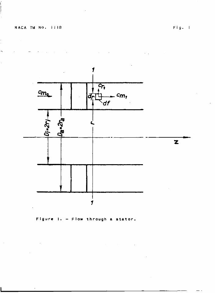
The flowas foundbehinda statoralonewIU. firstbe Investigated.That is, the respectiverotor is to be thoughtof as not yet put inplaoe. Fl@lYe1 schematicdJYpresentsan axialsectionthroughsucha stator. The statorbladesoccupythe annularspaoebetweenthe innerdlamter Di and the outerdiameter Da. A systemof polarcoordinatesso @aced in the statorthat z fallsalongthe axis of the turbine,r Is the distancefromthe axis of ?mtatlon,and c Is the anglemustbe imagined.The statorbladesare understoodto be so closetogetherthat the smallvelocityvariatio~ acrossthe blade SpaCiIW can beneglectedand the flowregardedas sziallysymmetrical,that 1s,
he owe thanksto ProfessorC. Hlelderer, Doctorof Ec@neerin6,for v~*ioussuggestionsto our work.
HAcA ZMmro. 1.U8 3
..
independentof ~. The flow Is assumedto appmaoh the stator in.astrlct~vaxialdirectionwith a velocity ~ which is uniformoverthe whole cmsa seotlon02 the annularspace. ~. otherwords,thewhirl ccmqbtintof the velocityIS zero in frontof the stator. Atwist Is thengivento the fi,owby the statorblades. In theplane1-1 closebehiniithe stator,which Is to be the siteof thfollowinginvestIgation of velooityrelations,iet G , whichhss
FLthe components ~1, ~, and Crl, representthe ve oltyat thSdletancw r fromthe axis. Owingto the whirl component
9of
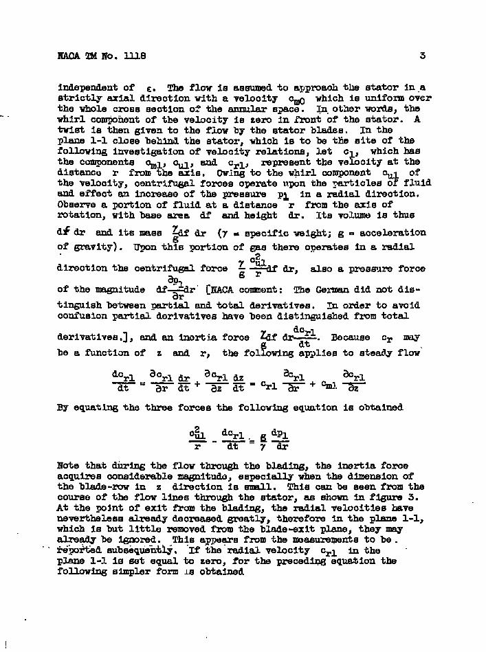
the velocity,contri~l f~~es opgrateupon the ~icles o fluidand effectan increaseo% the pressure pi In a radialdirection.Observea portionof fluidat a distance r fromthe axis ofrotation,with base area df and height dr. Its volumeIS thuEl
d~ & and Its mss & & (7 . sycif~c n@t; g - acceleration
of ~vity) . Upon this portionof -s thereoperatesin a radial
direotIon the centrifuged.force y %~~dr, also a pressureforce
%of the magnitude df+r” [NACA co?mnent:The Germandld not die-
tin@sh betueen~~fi snd totalderivatives.Zn orderto avoidconfusionpartialdorivatlveshavebeen disti~hhed fromtotal
derivatives.],and an Inertiaforce & dr~. Because cr maY
be a functionof z and r, %the f01 wing applie6to steadyflow’
By equatingthe threeforcesthe followingequationis obtained
o& dcrl ~ dpl—-T-r “-7T
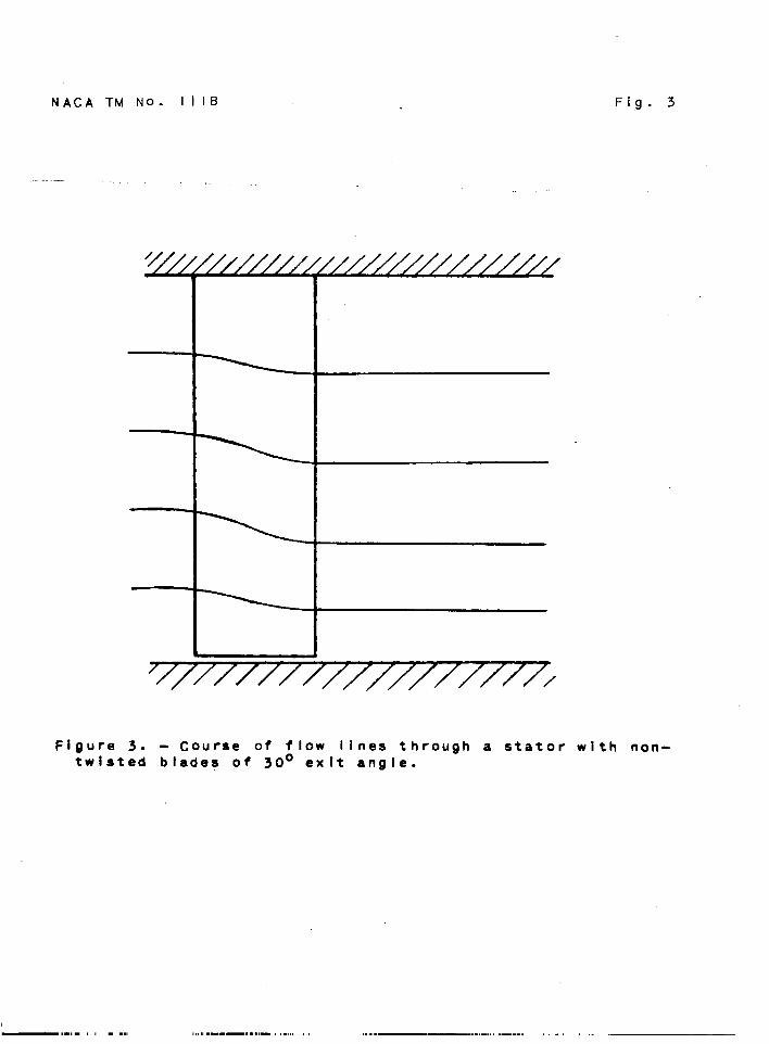
Note that dti~ the flowthroughthe blading,the inertiaforceacquiresconsiderablemagnltudo,especiallywhen the dlmnsion ofthe bkde -ruw In z directionis enEJl. This can be seenfmm thscourseof the flow linesthroughthe stator,as shownin fIgure3.At the pointof exit fromthe blading,the radialvelocitieshaveneverthelessaJJXladydecmeased greatly,thereforein the plane 1-1,which is but littleremved fhum the blade-exitplane,theymayalreadybe -red. This appe~s fromthe measurmpentsto be .
“‘ i%~r%ed subseqtihti.j. If th -Id =&city Cr- h the “plane1-1 is set equal.to zero,for the precedl~ eqtilon thefollowlngsimplerform M obtained
—. —
4
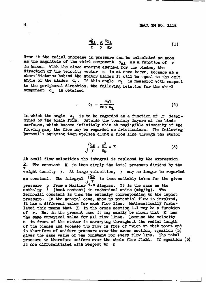
(1)
From it the radial increase In pressure can be calc~tj~d an ~onas the magnitudeof the wh~.rlcomponent ~fl as a functionof r
Is lmown. With the closespac~ assumedfor the blades,tkedirectionof the velocltyvector c is at once *, becauceat ashort”distancebehindthe statorbladesit will be equalto the exitEU@S of the blades ~. If thisangle ~ is measuredw~th rxpctto the peripheraldirection,the followingrelstionfor the whirlcomponent ~ is obtained
wcl.—
00s q
Inwh?.chthe angle ~ is to be regardedas aminedby the bladeform. outsidethe boundary
(2)
functionof .r deter-l.ayeraat the blade
surfaces,whichbecomeinfinitelythin at negligiblevlficocltyof theflowinggas, the flowmay be regardedas frictionless.The followingBernoulliequationthenappliesalonga flow linethroughthe stator
‘~+:.KJ (3)7
At smallflowvelocitiesthe integml is replacedby the expression~. The cciustantK is then simplythe totalpressuredividedby the
weightdensity 7. At largevelocities,7 v no longerbe regarded
‘a Is then suitablytakenfor the Given~
as constant. The inte~ y
pressure p froma Mollier1-sdiagram. It is the sameas theenthalpy i (heatcontent)in mechanicalunits (mkg/@). ThoBernoulliconstantis then the enthalpycorrespondingto the impact~ressure. In the gene- case,when no potentialflow is involved,it has a differentvaluefor each flow line. Mathematicallyformu-latedthismeansthat K in the crosssection1-1 may be a functionof r. But in the presentcase it may easily”beshownthat K hasthe sam numericalvaluefor all flow lines. Becausothe velocityc in frontof the statoris unvaryingthroughoutthe radialLx@hof the bladesand becausethe flow is free of twiotat thatpointtiis thereforeof uniform pasure overthe crosssection,equatioa(3)givesthe sem valueof the constantfor everyflow line. The totalpressureis thereforeunifom over the wholeflow field. E equation(3)is now differentiatedtith respectto r
—-.. . 1
—. .- .. —
MAcA TM IJlo.11.M
. .By a~lyhg the eq&t Ionthe ~xmsaureby nBans Of
5
~*+QQ=o (4)7dr gdr
to tb crossseotion1-1”and eltilnatlngequation(1)
[5)r ‘L dr
.-
In Orderb substituteits uerlmheralcommnent for velooity o, InequatIon (5),equation (3) h d-~erentia~edwith resysotto rA
d??
Therebyequation(5)
%
r
or
00s al &
beoome
1 d%-— —COS2ul dr
A
de... /’00s2G
~@ncL@cJ
coe2ol dr6)
(7)
(8)
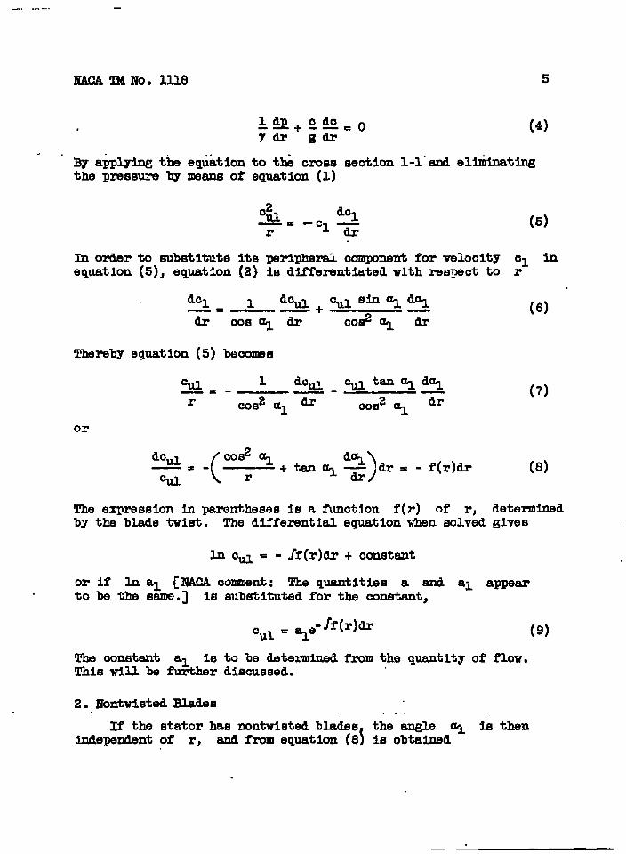
~ expressionin parenthesesis a funotlon f(r) of r, determinedby the bladetwist. The dlffezwntI&l equatIon when eolved@ves
in o~ = - Jf(r)dr+ constant
or if & al [NMA oonment: The quantitiesa and al appearto be the same.] is substitutedfor the oonstant,
Cul = ‘%.”-Jf(r)&
The oonstant al is to be determinedfromthe quantIty of flow.ThiswI1l be further discussed.
2. ZWontwistedBlades ..If the statorhas nontwlstedblades the angle al is then
Independentof r, and f?xm eqpation(8\ is obtained
.
(9)
.— . -— --- —_ _
6
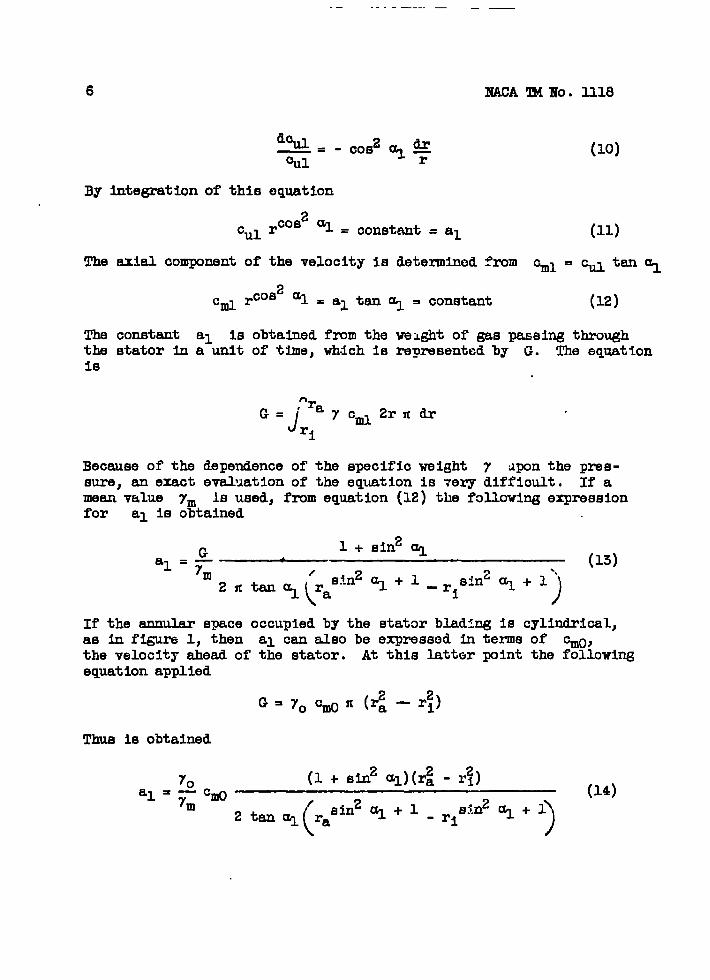
By Integrationof this
%1
The axialcomponentof
df+QCOS2y kT71=- r
equation
rcoszal = conetant= al
the velocityIs determined
2q=alt~%Cml rcos = constant (12)
The constant al is obtainedfzmm the weightof gas passingthroughthe statorIn a unit of time,which is representedby G. The equationIs
‘raG=’
Jycm12r7rdr
ri
Becauseof the dependenceof the specificweight 7 ~ponthe pre6-sure) an exactevaluatIon of the equatIon is ~ery diffIcult. If amean value ym 1s used,fromequation(12)the followingexpressionfor al Is obtained
If the annularspaceoccupiedby the statorblad:ngIS cylindrical}as in figure1, then al can alsobe expressedin term of ~,the velocityaheadof the stator. At this latterpointthe followingequationapplied
G=yocwfi(g-lf)
Thus is obtained
70 (1+ sln2al)(r~-~)—%0 (14)
al = 7m
(
‘sin2Ul+l2tanul ra - ri)
sin2~ + 1

-.
The ourve of pressureover the orosasectionl-l Is obtainedfromequation(3). If the velocityat the inuerdiameteris repreaezrkd‘as.cilj t~n .. .. .
(15)
and,takingaocountof equations(2)and (U),
.r
J -+dl -(92*S2‘1dpl
‘i. Y(16)
.
The quantityJ
A ~ representsslmpl.ythe negativevalueof’theY
rlheat dropbetweenthe reapeotIve radi1 In questIon. From it withthe aid of the entropydiagram,the pressuredifference Ap oan at
Ir Q .42. Eqllatloris(m,onoebe taken. At smallflowvelocjtleari 77
(12),and (16)are numericallyevaluatedIn figure2. As only exhi-bitionof the variationof the velocityis considered,the axialvelocityat the innerdiameter Cml
lbIs set equaito 1. The calcu-
lationhas been carriedout for two lade-exitangles,3@ and 450.The dashedcurvewill be dlscuseedlater. Eehlndthe statortheaxialcomponentis no longerunlfom thzmughcutthe lengthof theblades. It is greatestat the Innerdiameterand decreasestzwrardthe outerdiameter,that 1s,the flow is”defleotedtowardthe axisof mtat ionby the etator. The courseof the flow linesIn passingthrougha statorwith uontwlstedbladesof 3C)bexitangle is shownIn figure3. The courseshownfor the flow lineswithintbe bladlng1s eetlmated.
3. IrrotationalSpiralFlow
With twistedbladesit is possible,by appropriatechoiceofblade-exitangle,to achieveuniformityof the velocitycomponent~ throughoutthe lengthof bladebehindtb statoras well asaheadof it. In this ease it followsf’mm‘&e BernoLilli equation. . “’that ‘ “a‘ .,,
r
P %? K—+—= (17)Y 2g
—. . .
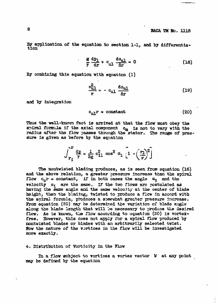
of the equationto section1-1,
g dpl +
Y=
By comblnlngthis equationwith
2“e.1
%11 o‘ti~=
equation(1)
-LIAa%
—=-cL1—
r -u &
and by tite~tion
cdr = constant
and by dlfferentla-
(18)
(19)
(29) “
Thus the well-knownfact is arrivedat that the flowmust obeythespiralformula if the axialcomponent ~ is not to vary with theradiusafterthe flowyassesthroughthe stator. The rangeof pres-sure is givenas beforeby the equation
The nontwietedbladlngproduces,as IS seenfrom equation(16)and the aboverelation,a greatergrefwureticreasethan the spiralflow cur = constant, if in both casesthe angle ai and thevelocity c1 are the mm. If the twu flowsam postulatedashavingthe sameangleand the sameveloc.ltyat the centerof bladeheight,then the blaiing,twistedto producea flow In accordwiththe spiralformula}ptiducesa smevhat grmzterpreesureincrease,I%om equation(20)may be .detemninedthe variationof bladeauglealongthe bladelengththatwill le necessaryto producetLe desiredflow. As is known,the FIovaccoidlngto oquatlan(20)IQ vortex-free. However,this doesnot applyior a spiralflow producedbynontwistedbladesor bladeswith an arbitrarilyselectedtwist.Now the nat’ure of the v~tiicesin the flowwill be investigatedmore exactly.
4. Dlstrlbutlonof Vorticityin the Flow
h a flow sub~ectto vorticesa vortexvector W at any mintmay be definedby the equation
m4cA TM Ho. Ille 9
w = rotation E (21)
. . . .- !l?he..vedor.1s here.deslgnated by-the mean llne. One ~ the valueof this vortioitygivesthe angularvelocity~th whiohthe neigh-boringfluidpartiolesrevolveaboutthe veotordimotlon as an axis.TIM oaloulationof the vortexstzwngth W oan be made with the aidof the mobs theorem. This theoremstatesthat everyoomponentofthe vortioityis equalto the clroulatlondI’ arounda smallsurfaoeelementstandingperpendicularto the directionof the veotoroom*ponent,dividedby the magnitudeof this surfaceelement df, thatis
W=g (22)
With the aiflof this theoremthe threecomponentsof the vortloitywill be detezmhed. In orderto oalculatethe oomponentIn theperipheraldirection Wu, the oiroulation,that is, the line .Integralof the velooityarounda smallsurfaoeelementhavingsidesof length dr and tlz (~ig.1) must be developed.At adistanoe r fromthe axis of rotation,the azialvelocityexists. The 1= titegralalongthe Mnear element dz has%% ere-fore at this yolntthe value ~ dz. At the distance r + dr
the euialvelocityIs %1 + *. At this secondpointthe line
Integralalong dz thereforehas the value
s!
d~ ~‘% + _#r)dz ●
Alongthe line= element dr the line integr Is zero,becauseth -id veloolty cr iS igno~d. AS the s~ of all the 11-integralspertainingto ciroulatlonaroundthe surfaceelement,is thus obtainedthe expressionfor clroulatIon
and when dividingby the surfaoearea,the following~mssionfor the tangential oomponentof the vortexstrength
The axial v+ooity %1 is givenby the relation%l=%lt~%” Thue eqpation (23) beoomes
.
b
~!lldllo. 1118
a~By substitutionof the vall:eof the derivative ‘~ from equation(8)
(24).
~ onlerto obtainthe axialcomponent W 1 of the vorticity,the cticulationabouta surfaceelementwith t~e dhensims dr andrileuruetbe developed. The line lnte~ along rdc at distance rfromthe axis 1s ~lrdc. _Asth? distance r increasesby dr, the
d(r~) ~line integralchangesby ~11 . Becausealong dr are zero,the clrc%&iGn aroundthe
the Mne integralssurfaceelomontis
The vortexstrengthobtainedby dividl~ this eqrat:onby the surfaceama is
Againeliminatingthe derivativeI
d~l dr by
‘ml =’~%@P&$-
The radial componentof the vortlcityis zer~
(25)
meansof equation(8)
(26)
becauseof the =ialsymmetry. Couequentlythe vectorlies in a CJlindrical smfece(r = constant)and is ab an an@e “8 to the peripheraldirection,which Is calculatedfrom the equation
‘mltan6=~
U1
By substitutingthe e~resslons for the two vorticltycmponents
& .a (27)
I
XL
Thus the vortexfilamentstravelIn the ~nt at the exitangleof the statorbladlng. This resultis in agreemnt with a generalh@rOdynam~ctheoremthat vortexfilamentsand ourrentfilamentsmust ooinoide,If for the flow in questionthe BernoulliequatIonwith a fha valuefor the oonstant K appliesuniversally(refer-enoe 4). - suchvortioesoome intoexistenoein a currentofnegligiblefrictionwas”shownby Frandtlin his explanationof theinduced?xmlstsnoeof alrfoils.
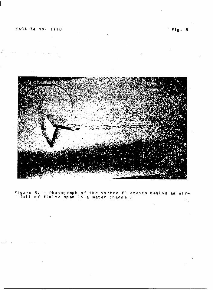
An airfoilof Infinitespan in a.friotlonlesscurl%ntis sub-~ectto a foroeperpendicularto the dlreotlonof tk free-streamvelooity,if intothe otherwisevortex-freecurrenta olroulationis Introducedaboutthe airfoil. The flow aroundthe ahfoil isthen oomposedof a olroulation-freestream flowingpast It plusthe oiroulation flow,vhiohat a greaterdistanoeoormsponds tothe flow fIeldof a potentid. vortex, Thereforeas a f Irstapprox--tlon the airfoilcan be Ilm@ned as zwplaoed“bya ptent Mlvortex. Suoha vortexid subJeotto ths rulethat it must eitherform a oontlnuousolrouitor extendto Infinity. If the aiflollIs of flnltespan,the vortexwith whichthe airfoilhas beenreplacedmust be pioturedas beingbent resrwardsat both ends.See figure4(a). The true flow relationsaroundthe a~oil willbe evenbetterrepresentedby consideringIt as replaoedby awhole seriesof vortices,whiohbend rearwardsat varyingdis-tanoesfromthe airfoileds. See fi- 4(b). Thusbehindthealrfollis obtaineda surfaceof discontinuity,whioh is entirelycomposedof adJolni~ vortexfilaments.The distributionof thevortioesoverthe chordof the airfoilis determinedby the factthat in everyseotlon1-1 the vortexfilaments~ssing throughthat cressseotiontill produoeJustpreoiselythe ciroulatIon thatexistsat this looationon the airfoil. A variationIn oiroulatlonaboutthe airfoiloocurringbetweensections1-1 and 2-2 correspondsthereforeto a definitenumberof vortexfilamnts, whiohleavetherear edgeof the airfoilIn the area between1-1 and 2-2. The vor-tioesleavingthe alrfollmay be verynicely_ visibleh awater channelby the Introduotlonof ‘airIn the vortexaxis. Sucha flowp“loturemade by H. Dresoherof the Mrodynsmic ResearohInstituteIn G#ttingenis reproducedin figure5. Similarobsena-tionswem made on mine propellersby F8ttinger (referenoe5)and on airplanepropellersby Betz (referenoe6).
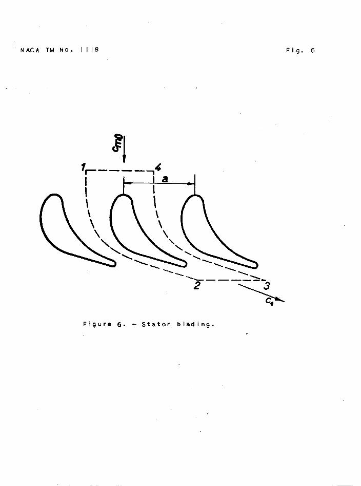
The samephencmmnonoooursin the statorunder InvestIgationwhetiverthe clroulation aboutthe Individualblade is variable‘x its l.m@h. But this is alwaysthe case If the flowproduoedby the statoria not aomrdlng to the spiralfomula ~r = oonstant.This may be seenfrom figure6, whioh showsa developedoyllndrioal
I .-. -
sectionthroughthe stator. The ciroulatlonabouta blade is obtainedby developingthe line titegralalongthe path 1-2-34. The partIaI.Integralsfor the two paths1-2 and 3-4 oanoeleachotherby reasonof synauet~If thesetwo pathsare exaotly1 blade Intervcilapart.Alongthe line 1-4 the velocityis perpendicularto the path of inte-gration;the line Integraltherewl~ consequentlybe zero; There “.remainsonJJTthe Integralalongthe line2-3 and the circulatIonazmunda bladbthezwforehas the value ra = ~~a, if a is theblade Interval. The line Integral.aroundthe clrmmferenoeIsraO #M,Y
or with n bladesIt Is n timesthe IndividualbladeG roulation re. For a flow In accordancewith the spiml formula,ths Mne titegralaroundthe oiroumferenoeis
ru .ou2m. “?- 2rJr= oonatant
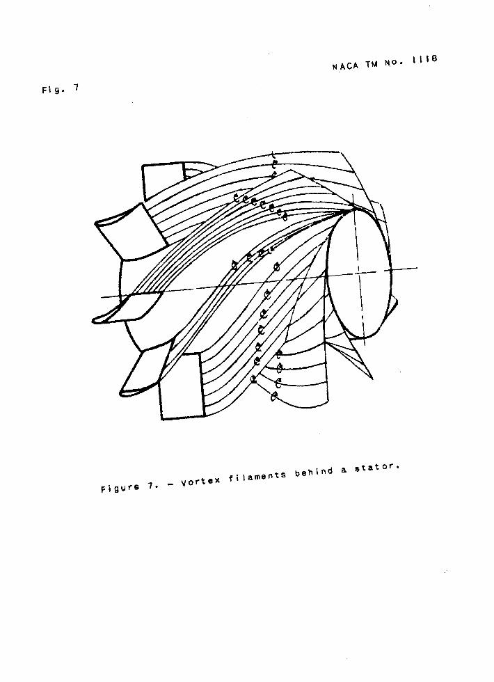
that 1s, inde~ndentof r. Thus the blade circulationis alsouai-formalongthe bladelength. If on the oontrary,the flow doesnotfulfillthe spiral-fomulaconditionf3,thenthe circulationaroundeachbladevariesthroughoutIts len@h. Consequently,a mass ofvortexfilmmmts passfrom the trailingedge of the bladeintothecurrent. This Is shownIn figure7. If the blade Intervalis nowreducedmore and more,thesesheetsof vorticltyalsoapproaohoneanothermore oloselyand finallyas Infinitelymall ldade intervalsare reaohedfill up the entIre flow fIeldbehindthe stator. Theprogressiontowardthe infinitelysmallblade intervals,whichemneces~ to achieveaxially“synmtricalflow,leadsthereforeto aflow,uniformlyfilledwith vortioes,of the fom derivedIn the “previousp~phs ●
III, EXPERIM!ZW?SON THE STATOR
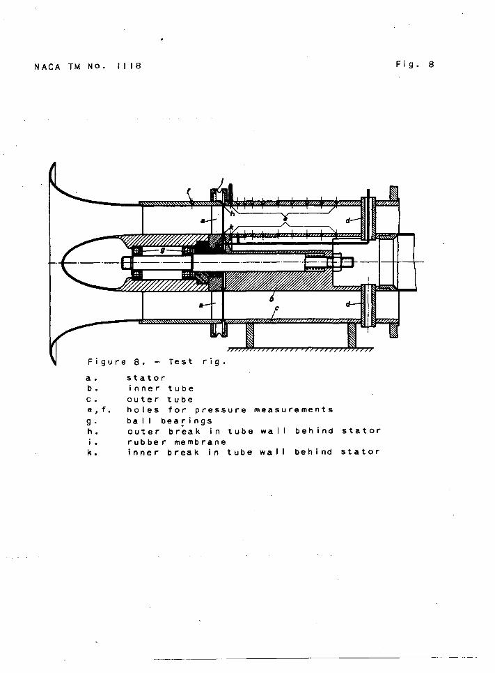
For the InvestIgatIon of tho spi- flowpmduoed by a statorwith nontwlstedblading,the test rig shown in figure8 was designed.The statoroocuplesthe spacebet%menth Innertube b of80+nil15neterdiametor and the outertube o of 160-millimeterdiameter. The ratioof radiiIs therefore2 and the differenoeofpressureti a radialdireotlonmay be expectedto be dlstinctlymeasurable.In orderto obtaina flowthroughthe statoras littledisturbedas possible,the air of the mom is sucbd throughthestatorby a blowerconnectedto the test rig through a ratherlong
. pipe. Special.importancewas attachedto the accumte installationof the statorbladesti.order to securea satIsfaoto~ axialsynme~ryof flow● Theywere set betweenthe innerand outer tubesby aspecial.techniquewith the aid of a dlvidlnghead. The bladesection
EAcAIMIro. lllA 13
. . .
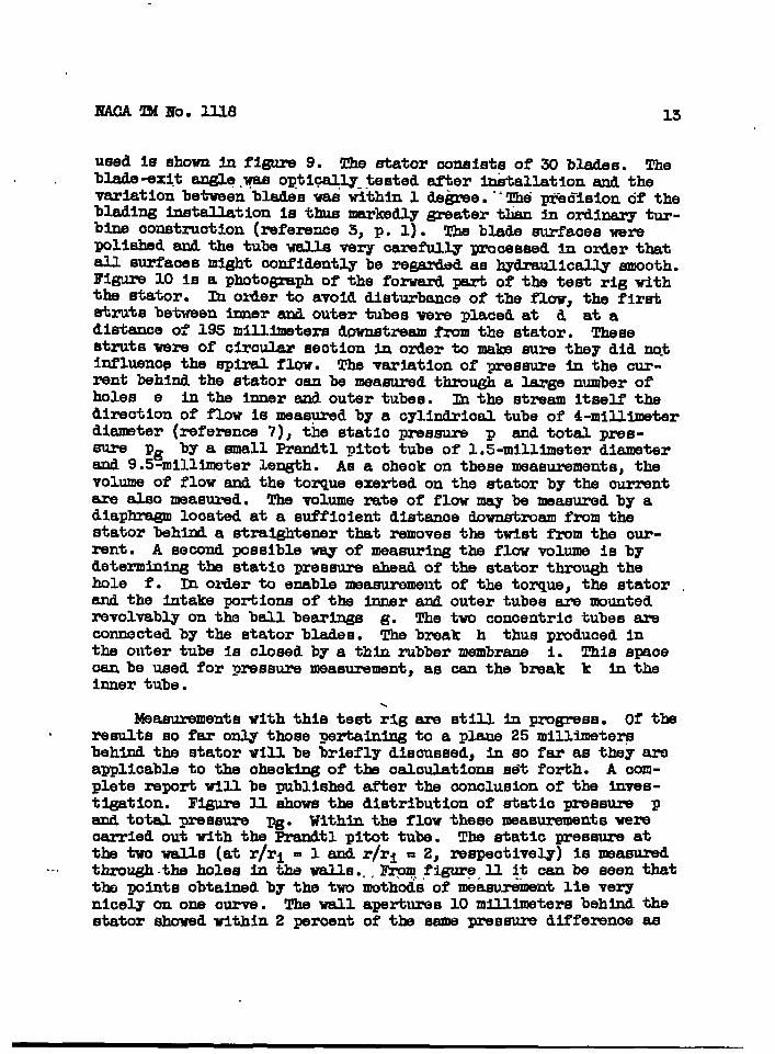
used Is Elhownb figure9. The statoroonsistsof 30 blades. Theblade-exitangle.yasoptlcsJJy-testedaf%ertitallatlonand thevariationbetweenbladeswas within1 de~e. “‘The pi%disionof thebladingInstallationis thusmrkedly greatertlianh ordlnerytur-bine construction(refereaoe3, p. 1). The bladesurfaceswerepolishedand the tubewallsvery oarefull.yprooemed In orderthatall surfaoesmightconfidentlybe regardedas hydraulicallysmooth.E’isare10 iE a photogmph of the forward~ of the teat rig withthe stator. In otierto avoiddisturbanceof the flow,the firststrutsbetweenInnerand outertubeswere placedat d at adistanoeof 195 millimeters@wnstream from the stator. Thesestrutswere of clroularseotionin orderto mab surethey did notInfluenq the spiralflow. The varlatlonof pressurein the cur-rent behindthe atatoraan be measuredthxmu@ a largenumberofholes e In the inner~ outertubes. ~ the streamitselfthedireotlonof flow is meaepredby a cylindrical.tubeof 4-millimeterdiameter(referenoe7), the statiopressure p and totalpres-sure pg by a smallPrandtlpitottube of 1.5-millimeterdiameterand 9.5-mllllmeterlength. As a oheokon thesenwaeurements,thevolumeof flow and the torqueexertedon the s-tatorby the ourrentare alsomeasured. The volumerateof flowmay be masured by adiaphragmlocatedat a sufficientdlstanoedownstreamfrom thestatorbehltia straightenerthatremovesthe twistfrom the our-rent. A secondpossibleway of measuringthe flowvolumeis bydeterminingthe staticpressureaheadof the statorthroughthehole f. In orderto enablemeasuzwnentof the torque,the stator .and the intakeportionsof the Innerand outertubesare mountedrevolvableon the ball bearings g. The two concentrictubesamconnectedby the statorblades. The break h thuspz,mducedInthe outer tube is closedby a thinrubbermembrane i. This spaceoan be used for pressuremeasurement,as oan the break k In theInnertube.
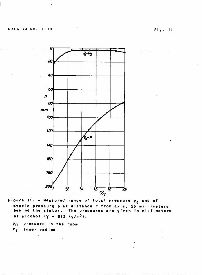
Measurementswith this test~lg are stillin pro~ss. of theresultsso far only thosepertainingto a plane25 millimeterbehindthe statorwill be brieflydlsoussed,in so far as they areapplloableto the cheoklngof the oaloulatlonesdt forth. A oom-pletereportwI1l be publishedafterthe mnolu~ion of the lnves-tigatIon. Plgure11 showsthe distributionof stat10 pressure pand totalpressure pg. Withinthe flow these measurementswereoarriedout ulth the Frandtlpitottube. TIM statIc pressureatthe two walls (atr/ri = 1 and r/ri = 2, respectively)is measuredttiugh -theholes in the walls...IhyJrn.~igureaI-1~t oan be seen that
the pointsobtainedby the two methodsof meamrement Me verynicely on one curve. The wall apertures10 millimetersbehindthestatorshowedwithin2 peroentof the samepressureclifferenoeas
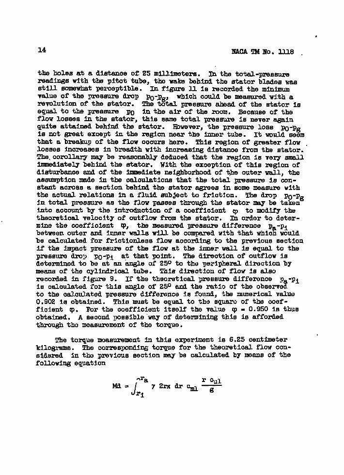
the holesat a diatanoeOE 25 millimeters.Ih the total-pres~readingswith the pitottube,tlm walm behindthe statorbladeswassti~ somewhatperoeptibla. In figure11 1s recordedthe minimumvalueof the pressure-P PO:pg) whloh couldbe measumd with arevnlution of the stator. The totalpressure*ad of the statorisequalto the pressure po In the air of the mom. Becauseof theflow lossesti the stator,this sametotalpressureIs neveragainquiteattaiti behindthe stator. E3wever, the pressureloss po-pgIs not greatexoeptIn the regionnear the Innertube. It wouldseemthat a breakupof the flow ooourshere. This region of greaterflow .lossesInoreasesin breadthwith inoreaslngdistanoefrom the stator.The.oorollarymsy be reasonablydeducedthat the regionIs very smallImsdiatel.ybehindthe stator. With the exoeptionof this regionofdisturbanceand of the Immediateneighborhoodof the outerwall,theassumptionmade in the oaloulationsthat the total~ssure is oon-stantacross a sectionbehindthe statoragreesin som measurewiththe aotualrelationsIn a fluld sub~ectto friotjon. The -P Po-Pgin totalpressureas the flowpassesthroughthe statormay be takenIntoaccountby the Introduotlonof a coefficientcp to mdif’ythetheoretIoalvelocityof outflowfrom the stator. lh ordor to deter-mine the ooeffioient V, the measuredpressuzwdlffereme p -pi
%betweenouterand inuerwallswill be oomparedwiththatwhit wouldbe calculatedfor frlctIonlessflowaooordingto the previoussectionif the impaotpressureof the flow at the innerwall.is equalto thepressuredroy po-pi at thatpoint. The d~otlon of outflowisdetemlned to be at an angleof 250 to the peripheraldirectionbymeansof the cylhdrhal tube. This dtiotlon of flow la alsorecordedIn figure 9. If the theoreticalpressuredifferonoe p -piis calculatedfor this angleof 25° and the ratio of the observetto the oaloulatedpreseuredifferenoeis found,the numerioalvaluo0.902is obtained. This mustbe equalto the squaroof the ooef-fIcient cp. lbr the ooeffIcientitselfthe value cp= 0.950Is thusobtained. A secondpossible“wayof determiningthis is affotidthroughtho measurementof the torque.
The torquemeasurementin thisexperimentis 6.25 centimeterkilograms. The correspondingtorquefor the theoretioalflow con-side~d in tho prevl~s seotionmay be calculatedfollowlngequation
by mans of the
—.
whtoh followsdirectlyfromthe prlnoipleof momentum. Afterinsertionof the exit angle al in this equationand expressionofthe‘velooity~componentsIn terms.of eqpations(Ill.)and (12),inte-grationgivesthe e~ression
F
sin (2 al) ra 3-2 OOE2 qh!d.yc~
L( Joil rl ..F
1-1
82sin2~+l
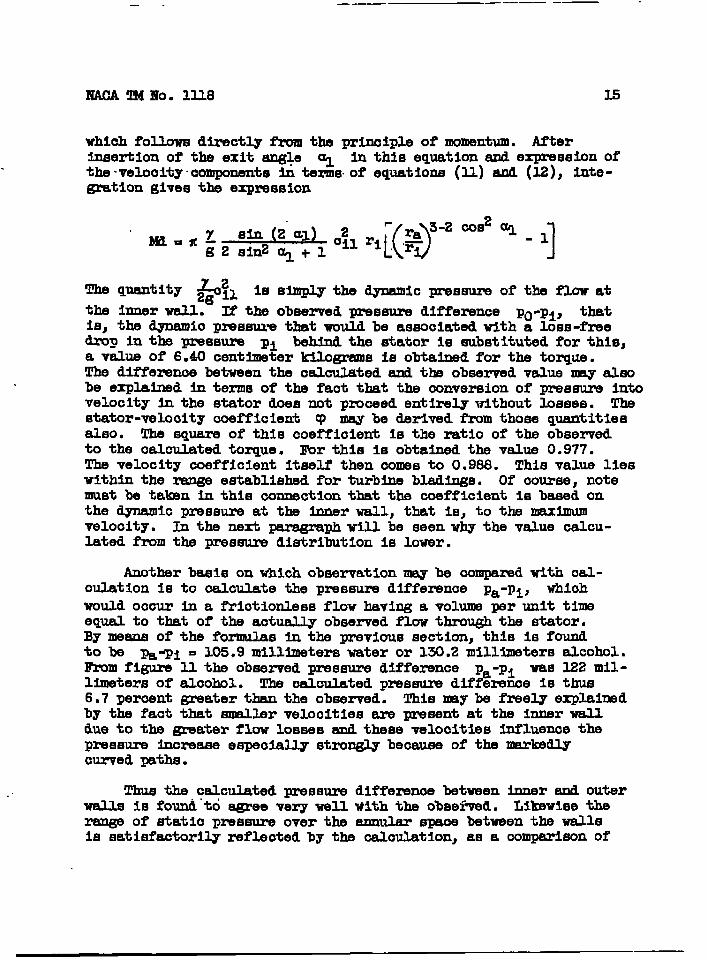
The quantity &il 16 Smply the dynamicpream of the flowatthe innerwell. If the observedpressuredlffemnoe pO-pi, that1s, the _io pxessuvsthatwouldbe aseooiatedwith a loss-freedrop In the pressure ml behindthe statoris substItutedfor this,a valueof 6.40centimeterkilogramsis obtainedfor the torque.The differencebetweenthe oaloulatedand the observedvaluemay alsobe explahed in termsof the fact that the conversionof pressureintovelocityh the statordoesnot pmxeed entirelywithoutlosses. Thestator-vel.cmltyooefflclent~ mey be derivedfromthosequantitiesalso. The squareor thle coefficientis the ratioof the observedto the calculatedtorque. lbr this Is obtainedthe vslhae0.977.The velocitycoefficientitselfthen oomesto 0.988. This valuelieswithinthe mnge establishedfor turbinebladlngs. Of oourse,notemust be talmn in this oonneotlonthat the ooefflclent is basedonthe dynamicpressureat the innerwall,that 1s,to the maximumvelocity. In the next ~ph will be seenwhy the value calcu-latedfrom the pressuredistributIon Is lower.
Anotherbasison whiohobservationmay be oomparedwltiuoal-oul.ation is to calculatethe pressuredifference pa-pi> whichwouldoomr In a frlctionlessflow havinga volumeper unit timeeqyalto that of the aotuallyobservedflowthroughthe stator.By meansof the formulas in the previoussection,this is foundto be ~-pl = 105.9millimeterswateror 130.2millimetersalcohol.Fmm figure U. the observedpressuredifference pa-pi was 122 mil-limetersof aloohol. The oaloulatedpressuredifferenceis thus6,7 peroentgreaterthan the observed. Thismy be freelyexplainedby the fad that smallervelocitiesare pawsentat the innerwalldue to the greaterflow lossesmd theeevelocitiestnfluenoethepressureInoreaeeespeciallystronglybecauseof the markedlyazrvedpaths.
Thus the ce2culatedpressurediffereme betweenInnerand Outerwalls is fo~ “toagreeverywellWith the obsei%ed. Lilmwisethe~ of staticpressureover the annularspaoebetweenthe wallsIs satlsfaotorilyrefleotedby the oaloulation,as a oomparleonof
—
‘..
16
figures 2 and U. shows. Thefrictionmy thusbe applied
~~ Ttd~O. 1118
calculations for a gas with negligiblealsoto the approximaterepmeentation
of the relationsIn a gaa subJeotto friotion, If the t%eoretIcalspeedsare modifled by the customarycoefficients.In so doing,ofcourse,the lossesare consideredas distributedequallyoverthewholelengthof blade;finepointssuohas the concentrationof theflow loseesat the Innerwall are naturallynot Included. The deflec-tion of the cuxrenttowardthe axis, indicatedh figure3, may bomade olearlyvisibleby the introductionof a ~treamr betweentheblades.
IV. CMCWM’IOM OF lZC#WTHROUG3THE R3TOR
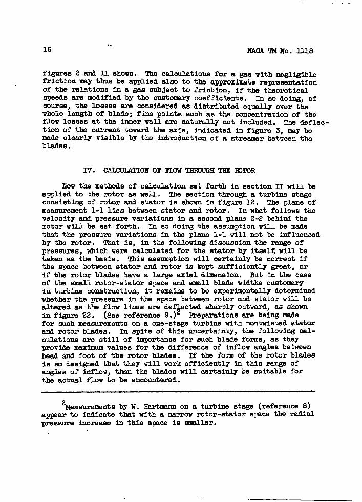
Now the methodsof calcuktion eet forthin section11 wI1l beap@led to the zmtoras well. The seotlonthrou@ a turbinestageconsisting of rotorand statorIs shownIn f@ure 12. The plane ofmeasurement1-1 llesbetweenstatorand rotor. In what followsthevelocityand pressurevariationsin a secondplus 2-2 behindtherotorwill be set forth. In so doi~ the assumptIonwill be madethat the pressurev~iailons In the plane 1-1 will not be itiluencedby the zwtor. That is, in the followingdiscussionthe rangsofpressures,whichwere calculatedfor the statorby itsel~will betakenas the basis. This assumptionwill certalulybe correctIfthe spacebetweenstatorand rotoris kept sufficientlygreat,orif the rotorbladeshave a largeaxialdimension.But In the caseof the smallrotor-statorspaceand smallbladewidthscustomryIn turbineconstruction,It remainsto be experimentallydeterminedwhetherthe pressureIn the spacebetweenrotorand statorwill bealteredas the flow linesare clef’ectedsharplyoutward,as shownin fIgure22. (Seereference9.)* ~parations are beingmadefor suchmeasurementson a one-stageturbinewith nontwlstedstatorand rotorblade~. h spiteof thisuncertainty,the followlqjcal-culatIonsare stillof Importancefor suchbladefurns,as they
providemaxm valuesfor the differenceof Inflowanglesbetweenhead snd foot of the rotorblades. If the formof the ntor bladesIs so designedthat theytillwork efficientlyIn this rangeofanglesof inflow,then the bladeswill certainlybe suitableforthe actualflowto bs encountered.
2Measurementsby W. Hartmannon a turbinestage(rsferenoe8)appearto indicatethatwith a narrowrotor-stators~ce the radialpressureixmreaseIn this spaoeis smallsr.
.
In figure12 the veloclty-veotordlagranmat entranoeto andexit fromthe rotoras shown. The absolutevelmitiea are desig-natedby 0. and the relativevelocitiesby w. The rotorvelocityat the givenradialdistame is designatedby u. Ths rotorbladesshallbe so rouzxledat the foreedge thatthroughoutthe rangeofInflowangleein questiontheywill permita flowaroundthe bladeswithoutseparatIon. The absoluteinflowanglesare designated a,the relatIve amgles ~. NJ. quantitiesreferri~ to pkne 1-1 arewrittenwith the subsoript1 and thoserelatingto plane2-2 withthe subsoript 2. The emergy drop}whlobundergoesconversionInthe stator$Is derxhd by h, that convertedin the rotorby h1.Thesetips are obtainmlfrom the adiabatioenergydrops In thsusualmanner, deduotlngthe energylossesoalouhitedwith the aidof the velooltycoetYlo@xktscp and $. Tho klnetlcenergyofthe Inflowvelooity o~ is also to be IncludedIn the totaldropH availableover the whole st~
2H=h+h’+~ “ (28)
the tip In the statorwe have
~ (o? - 0:)‘=2g (29)
oorresgondlngl.yfor the rotordrop
(30)
Thus the totaldrop can alsobe writtenas
2H=ht+~ (31) “
For the followingcaloulationsa statorhavingnontwistedbladeswill fIrstbe assumed. In the fInalseotionthe genera).methodOfml.oulationwill be given,whiohwill also includetwistedblades.In general,therealso existsa spiralat plane2-2 and henceapressureinoreasetowardthe outside. OnlYwhen the absoluteout-flow velooity from the rotorhas no peripheml oomponent,that 1s,when it is dincted strictlyaially, wllJ thereby @fozm pressuretithe plans2-2. TIM oalculation for this case is also the most .simpleone.
... .. .... .. . . . --

18
1. RotorwithAxialOutflow
From tha veloolty-veotordiapqm Zor therelatIve inflowvelocity W1 1s obtainedthe
NAoA !R4Bb.llla
ntor Inflow,for theequation
(32)
J!brthe relatIve outflowvelooity w2, the equatIon beoomessimplerbeoausethe whirloompnent ~ of the absoluteoutflowvelocity1s assumedto be zero.
Wg. og+u? (33)
Eenoefor the rotordrop fromequation(30)is obtainedthe relatIon
Solvingfor ~ gives
or tier intzwductionof the toti dmp E
(34)
(35)
(36)
BY tit~ductionof the valuesof Cti from equation(11)@ of therotorvelooity u fromthe equation n = rw ((I)= angularveloclty),the followingequationis obtained
(,37)
fzvm vhlchthe absoluteoutflowvelocity ~ fromthe rotorw kdetermined.
In figures13 and 14 the numerioalevaluatIonof this equationfor statorswith exitanglesof 45° and 30°)respectively,is presented.The intaketo the Btatorla here assumedto be strlotlyaxialand ofuniformvelooltythroughoutthe bladelength, The rotormust have
twisted bides so as to give at the rotors~eedseleotedan axialoutflow at eJl pointsalongtheirlmgth. The I.eadlngedgeof thebladesshallbe so designedthatno flow eeparatlonsh@l ooour.-
. (~~f%e-of-shock). ‘.~isoanbest be obtainedbya rounding-offof the lead~ edgeas shownin Hgure 12, Becauseonly relfztivemeasurementsare of ~rtanoe for the problemIn hand,the ratioof radii r/rl was msen as the absoissa. As onlyrelatIvevelooltiesare of oonoern,It is assumedthatthe axialveloolty
3andc+@r=l. .The rotorspeedis go chosenthat at the Inner
Iusthe pressure ~ is equalto p , that 1s,at the footofthe bladesthe rotoroperatesat equal~ressureon both sides. hornflguzws13 and 14 it oan be seenthatthe axialvelocity ~ = ~behindthe rotordecreases@ an outwarddinction in somewhatthesamemnner as the veloolty oti In frontof the zmtor.
In the lowerhalvesof thesefiguresIs also the degreeof reao-tlon R, that is, the mtio of rotordmp h‘ to totaldrop H, aswsll as the work output ~ impartedto the rotorat eaoh pointperkilogramof med:umflowlngthrough. The latteris obtained from theequation ~ = * ~~ u. ~ Is seenfromthe graphsthat the de@?ee
of reaotlon R “risesquitempldly alongt~ bladefmm toot toouterend. At 45° and ~ inflowanglesthe naction degreereaohes0.5 at radiusratiosof 1.9.~ 1.6,respectively,that 1s,thebladesoperatewith 50 peroentreaotionat thosepoints.
The work outputImpartedto the rotorlilmulseInoreasesout-- alongthe blade. The Bernoulliequation(3) ooneequentlyhasbehindthe rotora differentvaluefor the constaut K for eaoh flowM.nebeoausethe withdrawalof energyfmm each flow linewlthlntherotor Is differentIn amount. Furthermore,It is no longerneoessaryto fulfillthe oonditionthat the vortexfilamnts coincidewith theflow llnes. In reality,In the presenteasethe vortioityalso standsperpendicdarto the dheotion of flow Inaamuohas the axialoom-ponentof the vortlclty ~ (equation(25))is equalto zem beoauseof the entirelyaxialoutflowvelooity. Thusthe vortexfllamntspresentIn the ourrentIn this easerun aroundthe axis as dosedrings.
Zn figure15 is representedthe oourseof the flow linesthmugba turbinest~. The deflectionof the flow towardthe axis,whiohIs introducedIn the stator,Is onlyto a rathersmellde-e zwvereedin the rotor.
..
-. -—. — -— .— .— — — .—
20 moA !Q4No.I.lla
2. HontwlstedHotorBlade .
If the rotor is equippedwith nontwistedblades,it-is not pos-sibleto achieveaxialoutflowthzmghout the len@h of the blade.Becauseof the whirl componentpresentIn that case,a radialincreaseof pressureoccursbehindthe zmtor,wherebythe celculatIon is mademne dlfflcult. The d??OpH throu@ the ata@ IS therefoh alsonon-udform alongthe blade length. In orderto detezmlneit, the droph‘ In the rotor is firstcalculated.Rbr the relativeoutflowvelocity W2, the followingequationapplies
(38)
By insertionof the e~ressions from equations (38) and (32) h equa-tion (30),
(39)
The -P Inthe whole stagex JXW be expressedon the basisofequation(31)as
(40)
The dmp H is a@in equalho thepessure ~tegml
c
+. llhfg
equationreplacesthe Bezmoulliequation(3). Hence “expressionfor the radial-reaae of pressurebehind-, zwtoruan alsobederivedby differentIat~ with iespectto r
(41)
A secondrelation pertainingto the Increaseof pzessureIs alao tobe foundin equation(1),whichmust applyhere equallywell as anequilibriumof forces. In ordertoequation(41),the axialcomponenttermsof the whirl component ~.outflowla deducedthe equation
~=(u-
The velocity 02 is then
ellminatethe velocity 02 from~ wl~ be firstexprmsed InWornthe veloc~tydiagramfor the
(42)
----- .-— — —.. — .-— —I
.—- .. ...— .-. .—
-.
of this equationWith respemt
21
to r, it beoomea
By kisemtion of this relationin equation(41)and eliminationofq by meansof equatIon (1),the ~elooity‘oomponentOul by meansof equation(11),and the rotorspeedBY nwausof the equation
seveml transformationsIs obtained -
This is the defInltiveequationfor the determinantIon of thewhirl oomponent ~ of the outflowvelooity. It IEIa nonlineardifferentid equationof the ffistorder,whosegeneml eolutIonosnnotbe obtainedbeoauseof its complexconstruotlon.The mostsuitablemethodof solvlngIt 1s by Isoolinioalllnes. U8i~ thismethod,the numerlod oalculationsfor a turbinestagewith non-twistedstatorbladesof 45° exitanglewereundertalmn.The axialvelocitiesat tk Inner radius %1 and *i are againset equal.to 1. The rotorspeed1s so seleotedthat thereis equalpnasurebeforeand behindth foot of the rotorblades. U’urthermore, theexit angleof the nontwistedrotorbladesis of euohmagnitudethatthe outflowat the footof the bladesis entirelyaxial. The resultsof the oaloulationsam S- In f@urs 16 by the solidlines.
Althoughthe gmphic solutionof differentialequation(44)offersno particulardlffloultles,engineeringpraoticeneverthelessoonsidereIt undesi?nable.It will thereforebe best to lookfor ameansof simpllfy~ the oaloulation. ~r the mater numberofpractioal.cases,suoha mems is foundIn the faotthat greateffortwI1l alwaysbe made to obtainoutflowas nearlymfal as possiblethroughoutthe lengthof the bladesin orderto keep outflowlossesEmmJ.1.If the whirl components ~ of the outflowvelooityaresmall,then the radial-IWSEU3LUS inomases wild.alsobe small. Theradial-pressurelnoreaseoonwspondingto the relationsin fi~ 16is shownIn figure2 by the dashedline. It must be admittedthat,psrtioularlyfor smallertiius ratios,It is quite~11 as oom-paredto the radialpnssure Inoreasebehindthe stator. Tbnfore,investigatlonof whethera reliableslmplifIoationof the oaloulation
—.— —.—
. .
22 IuOA m No. IJJ.8
oan be obtainedby Igmring the pressuredifferenom alongthe len@hof blademy be -. The 8ts@ dXWp H is then UllifOZlllab~ tbszadius r oonstant. By substitutingin equation(30)only the valuefor the relativeinflowvelooity wl from equation(32),and thenaubptituting in equation(31)the valuefor the rotordrop, thedznp over the wholestage H is obtained
Further,fmm the outflow-veotordiagram
(45)
(46)
By insertionof this in equation(45)an equationfor oaloulatingthe axialoomponsntof the outflowvelooityIS obtained
(47)
as the outflowangle 132 Is determinedby the formof the rotor .blade,fromthis equationthe velooity
%nay be calculated.
~AhtiOutfti-vector diagramis t~n o ainedthe peripheral
%%2 ““-- (4a)
The veboities so calculatedare shownby the dashedlinesin figure16.In the lower portionsof the figureare the correspondingdegreesofreaotion R and the valueof the work output ~, whioh is novobtainedfromthe eqpatIon
% =; (%1-%2) (49)
As praotioaloases will not involvegoingmuoh beyonda radiusrat10 r~ri= 2~ the resultsobtainedby equations(47)and (46)may be regazdedas mafficientlydose a~xlmt ions.
It is observedfrom figure16 thatwith nontwistedbladesthe Euialoutflowveloolty ~ increasesbut slowlywith Inomaslng mdius r.The defleotlonof the flow tti the axisbehindthe stator has thusnow been reversedto a largeextent. The degreeof reaotion R againreachesO.5 at a mdius rat10 of r/ri = 1.9; on the otherhand,the
work outputticreasesvlth Increasing~iua slowlyat ftistandthen very sharply. At a mdiua ratioof r/ri = 2.4,the work out-put is alreadyzero. If the bladesare made stilllonger,the partso“f‘“ttibladbsIi5ybhda”tiius -t to of 2.4 till operate88 a blower,that 1s, theywII1 add energyto the flow. -t hilly, of oourse,a bladlngof suohheightis out of the questIon. The work outputmay be mademore unifozmalongthe bladelen@h If the ~iua atwhioh entIreaxialoutflowis obtainedIs Iooatednot at the foot ofthe bladjngbut furtheroutwards. This oan be seenfrom fIguXw17.Here the solidllnesrepeatlinesgive the valuesfor aentlreaxialoutflowomursobservedthatthe relationsaxialoutflowvelocity.
vlengthand the work outpuof mdius r. In figure18
the data of figure16 and the dashedse~nd rotorspeedso ohosenthattheat a radiusratio r~ri= 1.59 It iSthus obtainedare more favoxwable.TheiS more uniformthrou@out the blade
~ also fallsless sharplytith inoreasethe obrreswndingresultsare givenfor
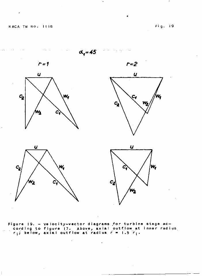
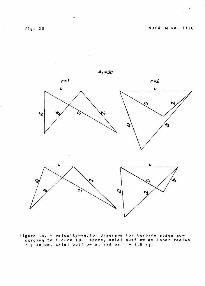
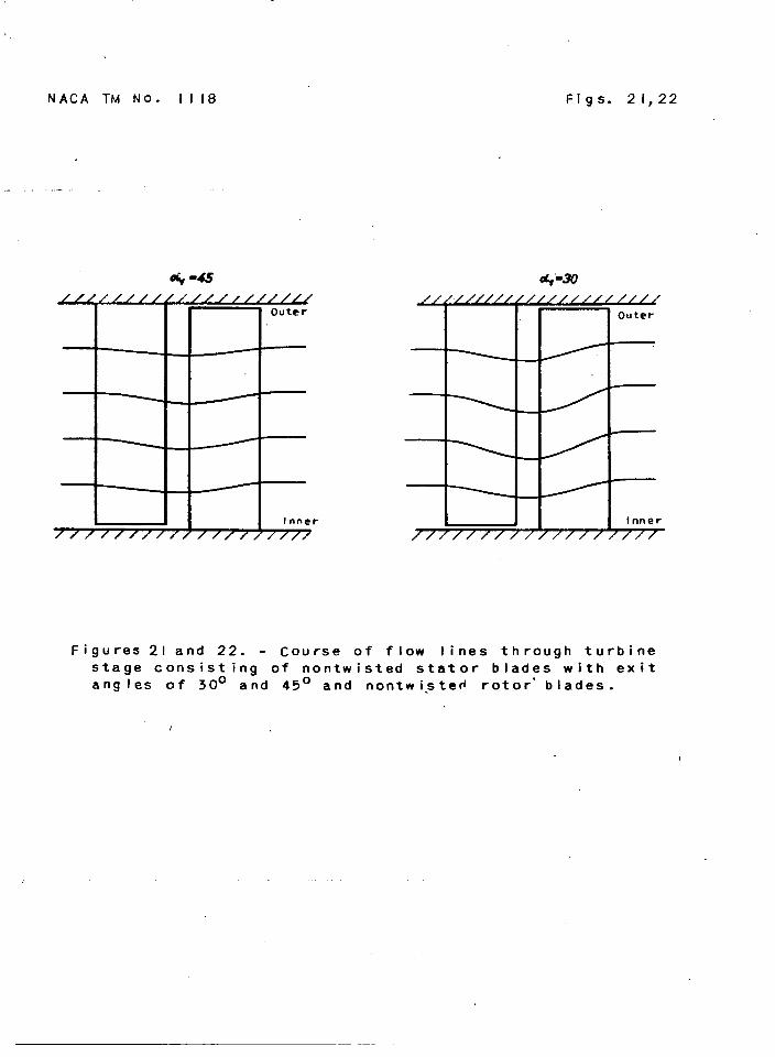
a statorwith an outilowangleof [email protected] The @enomena alre~ desrlbedfor the 4+ statorocmur here in still greater degree. In figures19and 20 the velocity-vector d-s are also shown,namely,In theupperrows for the rotor speed givingaxialoutflowat the footofthe bladingand In the lower rows for the speed giv~ axial outflowat r/ri = 1.5. The velocity-vectordiagramsare shownIn the formoustomaryfor waterturbines. This form is consideredclearerthanthat oustomary for fieam turbines. Figures 21 and 22 showthe Oourseof the flow linesfor the tuu outflowangles,respectively.The flowllnes In the @ane betweenstatorand rotorad behindthe rotoraredeterminedby the calculated~lal speeds WI and %2. The oourseof the flowlinesbetweentheseplanesis estimated.The figuresshow quiteclearlythe deflection of the flowby the stator,whichhas been frequentlymentionedabove. With nontwlstedrotor bladesthis deflectionis reversedin the zotor, But It must not be con-cludedfromthis that flowbehindthe rotorIs onoemore vortex-free.I’i@xres17 and 18 showthat suoh is not at all the case. Beoauseofthe marlmdbendingof the flow llnesIn the planeof an axialsection,whlohoooursat smll.outflowangles ~ (fig.22), oentrlfugslforoesam o?matedthat ~ssibl.yertend@to the spacebetweenthestatorand rotorand In that easewould oounteraotthe pressuretipIn the radialdirection.The drop In a mdial dlreotionIn thestatoroutflowvelocitywouldthus be diminishedand the flow llmsst~lghternd. The variationIn the reldive Inflow~les alongtherotor bladewouldbe lilmwlsed@nished. How far this phenonmonactually occurs remains to be determlrwd experlmsntally. “
.— —.. .-. .—
3. FractZealCakulation of a TurbineStage
In orderto oaloulatea turbinestagefor a oertainset ofprescribedoondltbns, it is unneoesmry to go baok to the equationspresentedin the foregoingsection;insteadthe OaloulatiopmEW beomhd out by makingsuitableuse of the hllier diagram. If theedlabatic stagedmp ~ is pr0a0tib8a,then the statordmp atthe Innerradlus
bIs firstseleoted. A =Imum valueno
greaterthanwill & the rotorto work at equal psmre at itsInnerradius (q = q) will be sebcteii. Of course,on ths otherhand the rotormay be all.ow8dto operatewith somedegreeof reactionat this point. JEom the stator dmp ~ , the theoreticalstatoroutflowvelocityis determinedIn the U6Ud mannerby meansof avelocitymale h the lWJ-iera-. Thetrue outflowvelocityla obtalmedby multiplyingby the velocityooeffIcient q. Thevarlatlonof exit anglealongthe bladelengthIs Presorted bythe bladeform. .- the bladeangleat the innerradiusthe whirlvelooityoompment ~il is obtained. Ww the variationof thewhirl componentfor the other mdii r alsomust be oalcul.ated.This is doneby meansof equation(11)for nontwistedstatorbladesor equation(9)for twistedstatorblades. Fmm the variationofthe statoroutflowangle,the variationof the outflowvelocity c1is obtainedand therewiththat of the statordrop h alongthe bladelength. The fact thatwith lar~ bledespacingthe outflowangleofthe flowno longerexact~ equalsthe blade-exitanglemay be allowedfor by an ‘angleexcess. If there is approximatelyaxialoutflowfmm the ?mtor,then in acco-ce with what has been saidthe pns -sure ~ behindthe rotorbladesand consequentlythe drop H maybe re~d as ~ifo~. Fromthe Mollierdiagmm the adiabaticrotor-P h’- for each mdius Is simplytakenand fzmmthis is obtainedby meansof equation(3) the theoreticalrelative rotor outflowvelocitY w2theo~t~calZ and by multlplicatIonwith the velocitycoefficientq), tho true relativevelocity ~. Now the Inflowandoutflowvelocity-vectordlagzwm can be drawnand the calculation ofthe stagecompleted.The calculationof a seoond stqp to be addedto the firstcannot,to be sure,be undertalmnwithoutfurtheradoin the samemanner,becausethe velocityof inflowIntothe secondstageis m longerpurelyaxieL,or entirelyuniformthzmghout thebladelen@h . For not too greatlengthsof bladethesevariations,whichaooordingto figures16 to 18 are not very largefor nontwistedbladesin sucha casemay pzmbablybe ignored,and the caloulatlonmay be oarriedout as for the firststage. In general,however,itmust be borne in mind that the vortexcurrent,which is here involved,undergoeschangesover greaterdlstanoesof travel,so thatwith
MAcA m No. 113.8 25
largernumbersof etagesIihe.prerequisiteoondltionsfor the oalou-I.ationare lesswell fulfilled. Its reliabllttyfor severalteuilemstagesthereforezwuainsto be testedexperimentally.
v. SuMM4Rx
. .etrongly
flow in-steamturbinesof considerablebladelengthisaffectedby the tioreasein prea~ fmm the axis outwmkl
In the &paoebetweenthe stator and ~tor. The same phenomenon Isobservable also in axial superchargers, whioh ma~ use of a ~drop in one stage and @nos operate with a pronounced s@@. flow.In order to obtain highefficiencyin euohmmhines, this phencmmnonmust thereforebe considered@ the bSi@l of the blades. Its ma-culationfor nontwistedand arbitrarilytwistedbladeehas thereforebeen given. The flowbehindthe stator1s fIrstconsidered,theassumptions.ofcloselyspacedblademand negligiblefrictionin thegas be- made. Thereafterexperimentson a statorare z%ported,which showthat the methodsof oalculation so obtainedalso refleotverywell the actualoonditionsin a gas subJeotto frictIon. Thenthe calculations are completedfor the courseof the flowbehindthestator. The resultsare shownin figures13 to 18 for nontwlstedstatorbladeswith exit anglesof 3@ and 450 and for nontwlstedandtwistedrotorblades. The de-e of reactionvariesconsiderablyover the bladedepthdue to the mdial Inoreaseof pressure. Witha statorbladingof 3@ exitangle,a rotorbladeoperateswith “50 percentreactionat Its outerend when eqyalpressureexistsatits foot and when the bladelengthis 0.6 of the inuerradius. Theflow thzmughthe stageis firstdeflectedtowardthe axis in thestatorwith nontwistedblades. This phenomenonis reversedin thezmtorand indeedeomwhat overcompensated,if the rotorbladesarealsonontwisted.
Translationby EdwardS. Shafer,nationalAdvisoryComitteefor Aezmautios.
I -.. _. . .. . .. —–
I 11 I
26 NAOA !l.?4No. lJ3.8
#
1.
2.
3.
4.
5.
6.
7.
8.
Stodola,A.: Die Za@turblnen. JulluE Sprxr (Berlln),4. Aufl., 1910. “
Ikurieus,G.: Contributionau Trao6dea aubesradialesdesTurbines. Ibstsohrift-f. Dr. A. Stodola mm 70. Geburtata&OrellF@ll Verlag,Zllrichund Leipzig,1929,pp. 92-95.
HEu’tmElnn, w.: Ausfluas- und lDaftmessungenan der Beohauflunge-r efnstufigenVersuohaturbineim Luftversuchsstand.VDI—Mreohungsheft397,Bd. 10, Jhly/Aug.1939,pp. 1-20. (BrltIshR.T.P.Trans.NO. 2393,MlnlstryAircraftProd.)
Legally, M.: IdealeFlffssiglmIten. Bd. VII, Kap. 1 of Handbuohd.Phys.,H. Geiger u. K. Scheel,ed., ilhliusSpringer(Berlln),1927, Po 18.
F&t inger, H.: Jahrb.d. D. Sch*tfYbauteohn.Gas.Bd. 19, 1918,pp. 385,472.
Betz, A.: C#ttingerl?aohrlchten,Bd. 1919,pp. 193,217.
Eck, Bruno: TeohnisoheStr8mungslehre.JuliusSpringer(Berlin),1941,p. 236. (Reprintedby EdwardsBros.,~o. (AnnArbor),1944.)
Hartmann,w.: Versuchean EinerDampfturbinenstufe.Arohivf#rWbwirtschaft, Bd. 22, Nr. 4, April 1941,pp. 87-89.
NACA TM NO. 1118
1
Fig. I
Figure 1. - Fiow through a stat or.
z
I
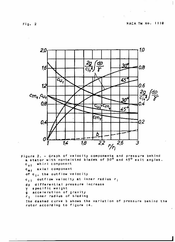
Fig. 2 NACA TM NO. 1118
cm,
20” l#o
A*&(*
b- 0,8
a m m
Figure 2. - Graph of velocity components and pressure behind
a. stator with nontw is ted blades of 30° and 45° exit angles.
CUl whirl component
‘ml axial component
of c,, the outflow velocity
C,i outflow velocity at inner radius ri
dp differential pressure increaseY specific weight
9 acceleration of gravity
‘i inner radius of bl ading
The dashed curve b shows the variation of pressure behind the
rotor according to figure 14-
NACA TM NO. 1118
/u
Fig. 3
Figure 3. - Course of flow lines through a stator with non-twisted blades of 30° exit angle.
—,,,., . , , .. . .. ,,,,,..-- —.... ,- , ,.,,. . . ....——— -.. -,-.,, .—.-. - . .
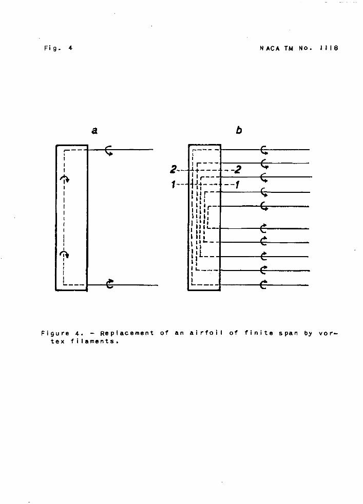
Fig. 4 NACA TM No= 1118
2.-
1-.
b
r-- -~
I
Figure 4. - Replacement of an airfoil of finite span by vor-tex filaments.
NACA TM NO. 1118
.
Fig. 5
Figure 5. - Photograph of the vortex filaments behind an air-foil of finite span in a water channel.
NACA TM NO. 1118 Fig. 6
Figure 6. - Stator blading..
NACA TM N,o. lt~8
Fig. 7
behind a st at or.f i laments
Flgurs 7. - vortex
.
NACA TM No. 1118 Fig. 8
v Figure 8. - Test rig.
a.b.c.e,f.
9.h.i.k.
statorinner tube
outer tubeholes for pressure measurements
ball bearingsouter break in tube wall behind statorrubber membraneinner break in tube wall behind stator
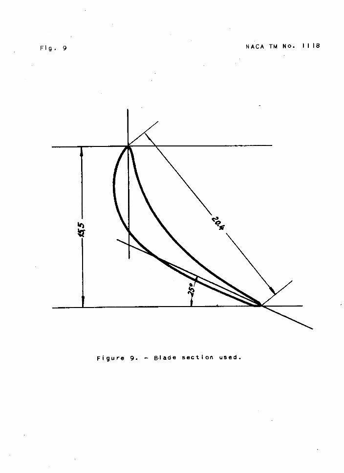
Fig. 9 NACA TM No. 1118
I
\
Figure 9. - Blade section used.
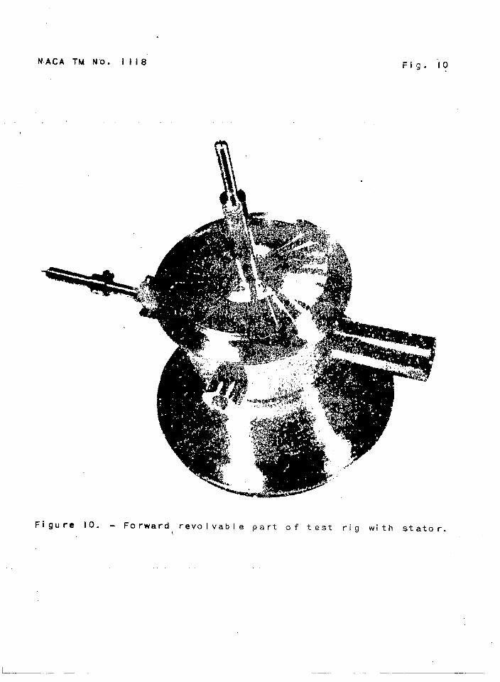
NACA TM Nt). 1118 Fig. “IO
Figure 10. - Forward revolvable part of test rig with st ator.
—— —
.
NACA TM NO. 1118
.
Fig. II
o
Figure Il. - Measured range of total pressure pg and of
static pressurq p at distance r from axis, 25 mil Ii metersbehind the stat or. The pressures are given in millimeters
of aicohoi {y - 8i3 kg/m3).
Po pressure in the room
‘i inner radius
- ..-
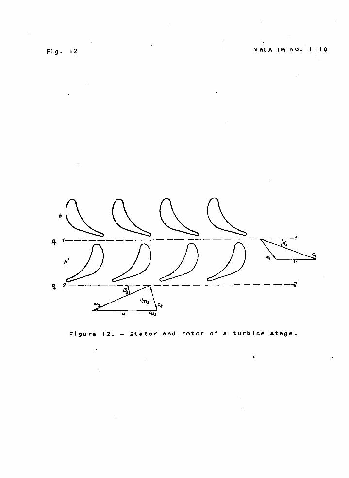
Fig. 12 NACA TM No. 1118
‘s II
——— — +’
Figure 12. - !jtator and rotor of a turbine stage.
I,
NACA TM No. 1118 Figs. 13, 14
e
.
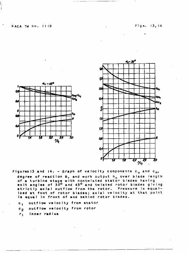
Figures13 and 14. - Graph of velocity components Cu and cm,
degree of reaction R, and work output hn over blade lengthof a turbine stage with nontw is ted st ator blades havingexit angles of 30° and 45° and twisted rotor blades givingstrictly axial outflow from the rotor. Pressure is equal-
ized at foot of rotor blades; axial velocity at that point
is equal in front of and behind rotor blades.
c, outflow velocity from stator
C2 outflow velocity from rotor
ri inner radius
.-

Fig. 15
.
NACA TM NO. 1118
*
T ///////// /Figure 15. - Course of flow lines through a turbine stage
with nontwisted stator blades of 30° exit angle and twistedrotor blades.

I
NACA 1rM No. 111849=45
Fig. ICj
hn
‘c~,
Figure 16. - Graph of velocity components cm and Cu, degree
of reaction R, and work output hn in a turbine stage having
nontw isted stator and rotor blades and fully axial outflowat inner radius r;c1 outflow velocity from stator
‘2 outflow velocity from rotor—exact calculation----approximate calculation
Equal pressure and axial velocity before and behind foot ofrotor blades.

Figs. 17,18 NACA TM NO. ili8
cc.&
BiU lZ
Figures17 and 18. - Graph of velocity components Cu and cm,
degree of reaction R, and work output hn of turbine stage
with nontwisted blades.
c, outflow velocity from stator
‘2 outflow velocity from rotor
axial outflow from rotor at inner radius ri
----axial outflow from rotor at radius r = 1.5 ri
Equal pressure before and behind foot of rotor blades.
. . ..
— __——.. ... . ,,, ..,!.! . . l.. . . . . .,..
—
,
NACA TM No. 1118
*=r
u
*
Fig. 19
df=~s ““ ‘“
—
c~
u
C&
Figure 19. - velocity-vector diagrams for turbine stage ac-cording t,o figure 17. AbOV,e, aXia~ outflow at inner radiusri; below, axi~l outflow at radius’r = 1“.5 r’i.
.
Fig. 20
r-l
u
NACA TM NO. il18
Figure 20. - Velocity -vect’ or diagrams for turbine stage ac-
cording to figure 18. Above, axial outflow at inner radius
ri; below, axial outflow at radius r= 1.5 ri.
NACA TM NO. 1118
. . . .
Inner
/////////////// ///]
Figs. 21,22
Outer
Inner
7/////1///////////
Figures 21 and 22. - Course of flow lines through turbinestage consisting of nontw is ted stator blades with exitang Ies Of 300 and 45° and nontwi.ste~ rotor” blades.
/
— ,.. .
lllll~ll~dg~~~~jllllll]””-’””‘“’”””’”””’’’””.-.
,,, ,J ,’
,.
-....—