national aeronautics and space ad washington · pdf filenational aeronautics and space ad...
TRANSCRIPT

REPLY TO A T T N O F GP
TO z
SUBJECT 2
NATIONAL AERONAUTICS AND SPACE AD WASHINGTON. D.C. 20546
USI/Scientific & Technical Information Division Attention: Miss Winnie M. Morgan
GP/Office of Assistant General Counsel for Patent Matters
Announcement of NASA-Owned U,S, Patents in STAR
In accordance with the procedures contained in the Code GP to Code US1 memorandum on this subject, dated June 8 , 1970, the attached NASA-owned U,S, patent is being forwarded for abstracting and announcement in NASA STAR.
The following information is provided:
U,S, Patent No.
Corporate Source
Supplementary Corporate Source
NASA Patent Case No,:
Gakle Parker
Enclosure: Copy of Patent
e--
(NASA CR OR TPAX OR AD NUMBER)
--
(CATEGQRY)
NASA-HQ
https://ntrs.nasa.gov/search.jsp?R=19710013685 2018-05-18T20:55:51+00:00Z

et.
Filed July 19, 1966
H. C. VYKUKAL
HARD SPACE SUIT
6 Sheets-Sheet 1
3 4- 63
INVENTOR HUBERT C. V Y K U K A L
ATTORNEYS
1968 H. C. VYKUKAL
HARD SPACE SUIT
Filed July 19, 1966
39.3:
6 Sheets-Sheet 2
27
49
INVENTOR HUBERT C. VYKUKAL
ATTORN EYS BY a

968 H. C. VYKUKAL
HARD SPACE SUIT
Filed July 19, 1966
27 28
3,
6 Sheets-Sheet 3
28 26 27
30 49
30 49
55
54'
30 9
INVENTOR HUBERT C. VYKUKAL
e -
ATTORNEYS

ck. H. C. VYKUKAL
HARD SPACE SUIT
F i l e d July 19, 1966 6 Sheets-Sheet 4
26
16
INVENTOR HUBERT C. VYKUKAL
BY ATTORNEYS
ct. H. C. VYKUKAL
HARD SPACE SUIT
Filed July 19, 1966 6 Sheets-Sheet 5
H. C. VYKUKAL
HARD SPACE SUIT
F i l e d J u l y 19, 1966 6 Sheets-Sheet 6
18
19 19
INVENTOR HUBERT C . VYKUKAL
ATTORNEYS

tat aten C
3,405,406 ACE
ubert @. Vyko nnyvate, , assignor to the ~ ~ t e d States of America as represented by the Ad- ministrator of the National Aeronautics and Space
stration Filed July 19, $966, Ser. No. 566,397
16 Claims. (CL 2-2.1)
5
environmental suit which will incorporate improved solu- tions to various problems previously mentioned.
More specifically an object of the present invention is to provide an environmental suit which has very low leak- age when pressurized to the desired internal pressure, and in which the mobility of the suit is not a function of the internal pressure. The present fabric type space suits op- erate at about 3.7 p.s.i. internal pressure. This is approxi- mately the partial pressure of oxygen in the earth’s at- mosprere. Consequently, only one gas, oxygen, can be used in the suit. This eliminates the capability of utilizing the advantages of a multi-gas mixture in the life-support A CT OF
A space suit of rigid material providing the wearer with system. The-reason that higher internal pressures are not extreme mobility and protection from the environment. employed is that soft suit mobility and leakage are a di- The suit comprises an upper body covering portion made 15 rect function Of suit pressure. At a desirable pressure Of of rigid material, a pelvic covering portion of rigid ma- 7.5 or 10 P.S.~., the astronaut in a conventional fabric suit terial, arm covering portions of rigid material, and leg would be essentially immobile, and the amount of gas covering portions of rigid material. The pelvic covering leakage would be beyond tolerable limits. In contrast to portion is connected to the upper body portion by gen- a fabric suit, a suit made according to the invention is erally circular metal waist bellows. Each of the leg cover- 20 constructed of hard material which is impervious to gas, ing portions is connected to the pelvic portion by means and the bearings which provide the articulation are sealed of circular metal thigh bellows. Each of the arm and leg in a manner which results in substantially less leakage podions is articulated by means of specially arranged cir- than with a fabric suit. In addition, the nature of the hard cular bearings. Each arm covering portion is coupled to suit construction is such that the pressure inside the suit the upper body covering portion by means of two inclined 25 can be increased to the desired value without reducing circular bearings. Life support fluids pass through the the mobility of the suit. covering portions. An additional object of the invention is to provide pro-
tection against extreme ranges of heat and cold and against meteorite penetration and radiation. The types of suit
The invention described herein was made by an em- 30 construction which can be achieved with hard materials ployee of the United States Government and may be man- are particularly adapted to accomplish the stated objects, ufactured and used by or for the Government for govern- as will be hereinafter described in more detail. mental purposes without the payment of any royalties A further object of the invention is to provide an en- thereon or therefor. vironmental suit which affords the wearer substantially
This invention relates to suits to be Worn in environ- 35 complete mobility with a minimum of forces acting in re- mental conditions which are different from normal at- sistance to the desired movement. In particular, the ob- mospheric conditions. In particular the invention relates ject of the invention is to provide an environmental suit to suits which will protect the wearer against the environ- having an improved articulation construction at the shoul- mental conditions encountered in space, and more spe- ders, elbows, waist, hips and knees. The low-resistance, cifically to a suit made of bard non-flexible material. 40 high-mobility articulation is provided in accordance with
There are numerous problems associated with providing the present invention by means of special arrangements a suit for use under the conditions encountered in space of rotary bearings and flexible bellows. travel. For example, a space suit must be pressurized on An additional object of the invention is to provide an the inside in order to protect the wearer from the vacuum environmental suit which is usable over extended periods which exists on the outside of the suit. In addition the 45 of time with substantially no deterioration. For example, suit must be capable of protecting the wearer against the in a hard suit constructed according to the invention, the extreme ranges of heat and cold encountered in space. leakage is substantially unaffected by use, whereas con- The suit must also protect the wearer against meteorite ventional fabric suits undergo an increase in leakage of penetration and radiation. The suit must be capable of fifty to one hundred percent over a relatively short pe- providing mobility for the wearer with a minimum of 50 riod of use. forces acting in resistance to the desired movements. In Another object of the invention is to provide an en- addition, the suit must be usable over extended periods vironmental suit which is relatively light in weight. of time with substantially no deterioration in its desirable Another object of the invention is to provide an im- features. proved articulated joint structure which can be bene- In the past the conventional approach to space suit de- 55 ficially employed in soft space suits and a variety of other
sign has involved the use of fabric materials. However, situations. fabric suits have not been completely successful in pro- An additional object of the invention is to provide a viding the desirable features mentioned in the preceding bearing and seal arrangement for space suits wherein paragraph. More specifically the leakage of pressurizing the seals present high resistance to leakage with relatively gas through the fabric itself is appreciable. Fabric does 6o low resistance to movement and also prevent bearing not provide adequate protection against thermal extremes, seizure by preventing exposure of the bearing materials physical punctures or radiation. When a flexible suit is to external vacuum environments. inflated it becomes very difficult for the wearer to flex By way of brief description an environmental suit it and make the desired movements. When a fabric or made in accordance with the invention comprises an up- other soft type material is made into a suit and internally 65 per body covering portion made of rigid material, a pel- pressurized it presents substantial resistance to bending vic covering portion of rigid material, arm covering por- and torsion, and the resistance does not disappear after tions of rigid material, and leg covering portions of rigid the movement has been made because the pressurized soft material. The pelvic covering portion is connected to the material has a continuous restoring force tending to re- upper body portion by a generally circular metal waist turn it to its original configuration. 70 bellows. Each of the leg covering portions is connected
It is an object of the present invention to provide an to the pelvic portion by means of circular metal thigh

3,405,406
bellows. Each of the arm and leg portions is articulated are sealed to the Iower ends of the leg portions. The by means of specially arranged circular bearings, and the gloves and boots can be of conventional construction bearings are sealed to prevent gas leakage and exposure employing flexible materials such as cloth and leather of the bearings to vacuum conditions. because the surface area of these parts is small in com-
The various features and objects of the invention will 5 parison to the surface area of the total suit, so that any become more apparent from the following detailed de- gas leakage through the gloves and boots is of minor scription wherein reference is made to the accompany- concern. ing drawings in which: In order to achieve the full objectiv
FIGURE 1 is a front elevational view of an environ- the walls of the covering portions 1 mental suit made in accordance with the invention; made in a hard, rigid honey-comb de
FIGURE 2 is a side elevational view of the suit of the representative example in FIGURE 10. As shown in FIGURE 1 but showing the arms in a different position FIGURE 10, the type of wall construction which can be than in FIGURE 1; used for all of the covering portions 1-6 comprises inner
FIGURE 3 is a partial top view of the suit of FIG- and outer skins 16 and 17 of glass fiber cloth held in URE 1; 15 spaced relation by separating ribs IS. The ribs 18 are
FIGURE 4 is a top plan view of the waist bellows re- also formed of glass fiber cloth folded into a ted moved from the suit; 18
FIGURE 5 is primarily a sectional view through the are first formed in the desired shape and the ted shoulder bearings and the elbow bearings and showing with resin to bond them together and res& in a rigid part of the elbow joint in elevation; 20 strong wall structure which is impervious to leakage of
FIGURES 6 through 11 present a series of views show- gas or liquid. In addition, the honeycomb construction re- ing the operation of the articulated joint cOnStrUCCiOn sults in a wall structure whicb has a high strength-to- employed at the elbows, which is the same type of con- weight ratio. As a result, the suit can be made compar- struction employed at the knees. More specifically, FIG- able in weight to conventional flexible fabric suits. In ad- URES 6, 8 and 10, respectively, show the front of the 25 dition, the ribs 18 form, together with the skins X6 and joint as it appears in the straight condition of FIGURES 14, a plurality of passageways 19 which can be used to 1 and 6, the partially bent condition of FIGURE 8, and channel fluids throughout the entire suit or various por- the fully bent condition of FIGURE 10. FIGURES 7, 9 tions thereof. The channels can be arranged in various and 11 are side views of the joint in the positions shown ways in different parts of the suit. Where it is desired to in FIGURES 6, 8 and 10, respectively. Indexing marks 30 terminate the passageways 19, for example at the ends of have been placed on the joint segments on each side of various portions of the suit, the inner and outer walls each of the bearings to indicate the relative rotational pass continuously around the end to form an end wall movement of the parts; 20 which closes the ends of the channels. At the end wall
FIGURE 12 is a perspective view on enlarged scale 20, alternate adjacent channels 19 can be connected by showing a representative cross sectional view of the con- 35 notched apertures 21 so that fluid flow can come down struction which can be employed for all parts of the suit one channel and back through the adjacent channel. Con- other than the bellows and bearings; ventional fluid coupling fittings (not shown) can be at-
FIGURE 13 is an enlarged cross sectional view of a tached to the wall construction to receive inlet and out- bearing and seal representative of all of the bearings and let hoses to deliver fluid to one channel 19 and remove it seals employed in the suit; 40 from another channel after the fluid has coursed through
FIGURE 14 is an enlarged cross sectional view show- the desired portion of the suit. Such fittings are preferably ing an arrangement which can be employed to conduct positioned at the back of the suit. fluids across the various bearings and is representative The described type of wall construction has been found of the arrangement which can be employed at all bear- to be extremely effective against meteorite penetration and ings; other types of punctures. A desired temperature can be
FIGURE 15 is a cross sectional view taken on the 45 maintained in the suit by delivering temperature con- line P5-15 of FIGURE 14; trolled fluids through the passages 19. When the Ruid is a
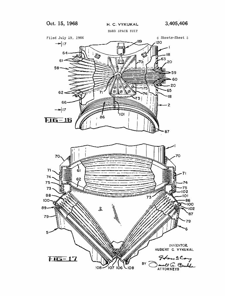
FIGURE 16 is a side elevational view on enlarged liquid such as water it serves the additional function of scale showing the waist and hip portions of the suit viewed protecting against radiation. In addition, the hard, non- from the left as in FIGURE 2, with parts cut away to flexing surface of the wall construction is well adapted to show the bellows construction and attachment; 50 have a layer of insulating material bonded thereto or to
FIGURE 17 is a view taken on the line By- 7 of receive a coating of reflective paint. FIGURE 16 and showing the waist and pelvic portions Although the honeycomb type of structure is preferred, of the suit as viewed from the front with parts of the it should be understood that certain features of the in- bellows cut away; vention can be accomplished by a solid wall structure of
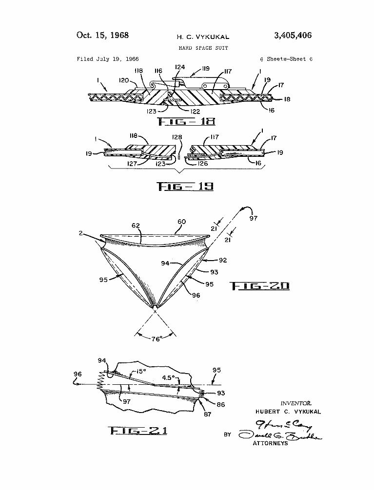
FIGURE 18 is a cross sectional view on an enlarged 55 relatively light weight material such as resin saturated scale taken on the line 8-18 of FIGURE 1 and show- glass fiber cloth or a thin sheet of light weight metal ing the latch construction at the separating line for don- such as aluminum. In addition, it should be understood ing and removing the suit; that a mixture of wall constructions can be employed.
FIGURE 19 is an exploded view similar to FIGURE For example, the upper body portion can be of the gen- 18 but with the latch removed and showing a different 60 eral type construction shown in R G U R E 12, and the re- position along the separating line; maining walls can have a single sheet construction. In
order to simplify the disclosure in the drawings, and be- portion on enlarged scale; and cause the multilayer wall construction would not show
up in small section views, the wall sections will: be leg openings in the pelvic portion of the suit as seen from 65 shown solid as if taken along one of the ribs 18, except line 21-21 on FIGURE 20. in such v ims as are intended to show specific features
Referring in more detail to the drawings and in par- of the fluid passageway systems, and these views will be ticular to FIGURES 1 and 2, the environmental suit ac- made on sufficiently large scale to show the composite cording to the invention comprises an upper body cover- wall construction.
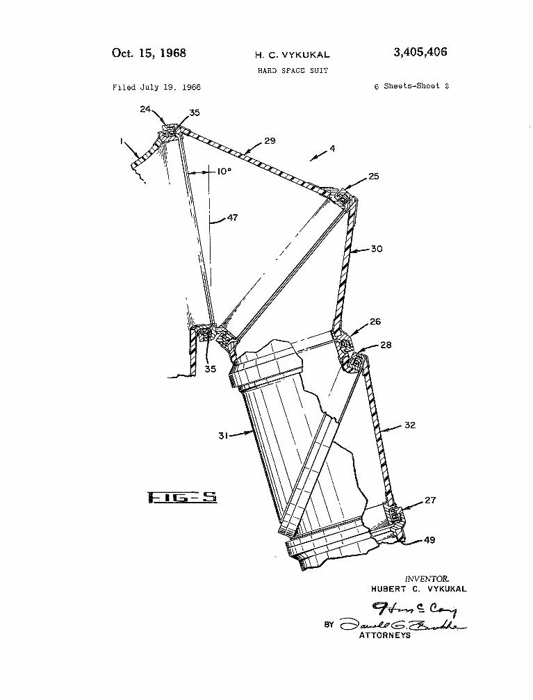
pelvic covering portion 2, arm covering 70 As shown in FIGURES 1, 2 and 5, and particularly the , and leg covering portions 5 and 6. A latter, the articulation for each arm is accomplished in
transparent helmet 7 of a material such as plexigiass is the following manner. Since the arrangement for each hermetically bonded to the neck opening at the top of of the arms 3 and 4 is symmetrical, only the arrange- the body portion I., gloves 11 and 12 are sealed to the ment for arm 4 will be described in detail. The arrange- lower ends of the arm portions, and boots 13 and 14 75 ment comprises a first shoulder bearing 24 which con-
patern as shown. All of the glass fiber cloth por
FIGURE 20 is a front elevational view of the pelvic
FIGURE 21 is a view along the edge of one of the

3.405.406
nects the arm portion 4 to second shoulder bearing 25, a first elbow joint bea 26, positioned above the wearer’s elbow, a second elbow bearing 27 positioned below the elbow, and an intermedi-
bearing 28 arranged diagonally between the bearings and 27. The arm portion comprises a tubular section between bearings 24 and 25, a tubular section 3@ be-
tween bearings 25 and 26, a tubular section 31 between bearings 26 and 28, and a tubular section 32 between bearings 27 and 28. Each of the bearings is a circular bearing comprising an inner race, an outer race, and a plurality of balls between the races.
Since all of the bearings are similar in basic con- struction, only the bearing 26 will be described in detail, as shown in FIGURE 13. Bearing 26 comprises a metal outer race 33, a metal inner race 3 and a plurality of metal balls 35. The inner race 34 is held in a metal at- tachment ring 36 which is secured to the adjacent tubular section 31, for example by way of an epoxy bond. The inner race 34 is held against movement in one direction by a snap ring 37, and is held against movement in the other direction by an annular wiping seal member 3,8 made of a plastic material such as nylon or Delrin. An outer attachment ring 39 is bonded to the tubular section 30, and the outer bearing race 33 is held in ring 39 by a threaded ring 40. O-ring seals are preferably employed at 41 and 42 as shown in FIGURE 13. The threaded attachment ring 40 has bonded thereto a circular ring 43 against which the wip seal 38 abuts to form the wiping seal line. The ring is made of plastic material such as Teflon. The pressure inside the suit forces the wiping seal member 38 into firm contact with the ring 43 to maintain a good seal. The ring-shaped seal member 38 is provided with annular weakening notches 44 and 45 so that fluid pressure inside the suit (on the left of member 38 in FIGURE 13) will more easily force the seal member 38 into contact with the ring 43. It is im- portant to note that the seal formed by the abutment of members 38 and 43 is on the outer side of the bearing balls 35 with reference to the inside and outside of the suit. In this manner the bearing races and balls are never exposed to any vacuum environment existing on the out- side of the suit. This is important because in a substantial vacuum, metal parts tend to seize together where they are in contact.
Referring again to FIGURES 1, 2 and 5, it should be pointed out that the plane of the balls 35 in bearing 24 (hereinafter called the plane of the bearing) is sloped inwardly at the top toward the vertical centerline of the suit, which centerline is coincident with the spinal center- line of the wearer. More specifically the plane of bearing 24 is preferably inclined inwardly at the top at an angle of approximately 1 0 degrees with respect to a line 47 (in FIGURE 5) parallel to the vertical centerline of the suit. The reason for inclining bearings 24 inwardly at the top is to make it possible for the wearer to move his hands together when his arms are raised above his head. Referring now to FIGURE 3, it will be seen that the plane of bearing 24 is also preferably inclined inwardly at the front of the suit at an angle of about 10 degrees to a line 48 (in FIGURE 3 ) normal to the frontal plane of the suit. The reason for inclining bearings 24 inwardly at the front is to make it possible for the wearer to move his arms across his chest. Bearing 25 makes it possible for tubular sections 29 and 30 to rotate in opposite directions so that the longer sides of sections 29 and 30 can rotate in opposite directions toward the armpit and permit out- ward movement of the arm.
The plane of bearing 25 is inclined clockwise in FIG- URE 5 at an angle of about 50 degrees from the pIane of the bearing 24. The plane of bearing 26 is inclined clock- wise in FIGURE 5 from the plane of bearing 25 at an angle of about 32 degrees. It should be understood that FIGURE 5 shows the arrangement of arm 4 when 6he
e upper body portion center points of all of the to lie in a common plane.
When the arm of the wearer is arranged so that the elbow is straight, the bearings 26 and 27 are substantially
5 coaxial and substantially parallel, as shown in FIGURE 5, and the intermediate bearing 28 forms an angle of about 50 degrees with each of the bearings 26 and 27. Although the usually preferred arrangement for bearings 26 and 27 is such that they have one position (the straight elbow position shown in FIGURE 5 ) in which they are coaxial, the axes of bearings 26 and 27 can be offset in order to conform to the arm configuration of a particular wearer without destroying the desired action. However, in order to avoid an undesirable twisting action when the elbow
15 is bent, it is necessary that the axes of bearings 26 and 27 be arranged substantially parallel to each other (in the straight elbow position) if the axes are offset from an exact coaxial relation. In other words it is necessary that the bearings 26 and 27 have one position (the straight
20 elbow position) in which the planes of the bearings are substantially parallel. The torque required to bend at the elbow is decreased the more that the angle between bearing 28 and bearings 26 and 27 is increased. However the magnitude of the angle is limited by the requirement
25 of providing a construction which will fit the normal wear- er’s arm. The forearm covering section below the bearing 27 is designated 49, and it is to this section that the glove 12 is sealed. It is possible that with extreme bending mo- tions of the arm, the various arm bearings can become so
30 oriented that they reach a dead center type of position which tends to resist return movement. Normally this resistance can be easily avoided, but, if desired, limiting stops (not shown) can be placed on opposite sides of each bearing so that the stops will abut each other before
35 the bearing reaches a dead center type of position. It might seem that the bearing 27 is superfluous in view of the presence of bearing 26, but the direct contrary is the case as will now be described in connection with FIG-
FIGURES 6 and 7 show the arrangement of the elbow joint when the wearer’s arm is straight, that is, when bear- ings 26 and 27 are substantially coaxial and substantially parallel. In order to show the movement of the various parts as the elbow joint is flexed, indexing triangles 50,
4:, 51, 52 and 53 are schematically marked on the arm por- tions 30, 31, 32 and 49 respectively, on opposite sides of the bearings 26 and 27. Similarly, indexing triangles 54 and §§ are marked on the arm portions 31 and 32, respx- tively, on opposite sides of the bearing 28. FIGURES 8
50 and 10 show the position of the eIbow joint sections as the sections 30 and 49 are moved toward each other about the bearing 28 as in bending the elbow. In performing this bending motion, the sections 30 and 49 are held so that they will not undergo any rotational movement, but the
55 force required to prevent the rotational movement is in- significant because of the bearings 26 and 27. It is im- portant to note in FIGURE 8 that as the elbow joint is bent, both of the arm sections 31 and 32 rotate as is shown by the displacement of the triangles 51 and 52.
(io The rotation of arm sections 31 and 32 becomes even more substantial the sharper the elbow is bent as shown in FIGURES 10 and 11. It will be understood from the showing of FIGURES 6-11 that if the bearing 27 were omitted, the forearm section 49 would be required to
65 rotate with the elbow section 32, as shown by the index triangle 52, SO that as the elbow is bent the wearer’s forearm and hand would be forced to rotate. This rota- tion would occur even if the forearm covering portion 33 were soft suit material because, as previously explained,
70 when soft suit material is inflated it becomes highly re- sistive to torsion.
Proceeding down the environmental suit, it will be seen that the upper body portion 1 is connected to the pelvic portion 2 by means of a metal bellows 58. Bellows
75 58 is sealed to the body and pelvic portions by an epoxy
URES 6-11. 40

3,405,406 7
bond. The lower end of the body portion 8, the upper end pansion due to pressure i de the suit, a pivot bearing of the pelvic portion 2, and the bellows 58 are all specially arrangement is provided across the bellows on each side shaped so that the bellows will be more open in the front of the suit. More specifically, as shown in FIGURES 16 than in the rear when the wearer is standing erect as and 17, a metal bracket 70 is attached to each side of shown best in FIGURES 2 and 16. More specifically, the 5 body portion 1, as for example by an epoxy glue bond. rear half section of the opening at the bottom of the body Each of the brackets 70 is provided with a short outward- member 1 has a rim 59 lying in a plane which is normal ly extending trunnion 71. A cooperating two-piece bracket to the axis of the body portion 1 and is substantially hori- structure is attached to each side of the pelvic portion 2. zontal when the wearer is standing erect. Similarly, the The two-piece bracket structure comprises a first tubular- opening in the upper end of the pelvic portion 2 is shaped piece 73 which is bonded directly to the pelvic provided with a rim QQ which lies in a horizontal plane portion, as by means of an epoxy glue bond. The second parallel to the plane of rim 59 when the wearer is stand- part of the two-piece structure comprises a plate 74 having ing erect. The front half section of the opening at the a bore in its upper end which has a rotational bearing fit bottom of the body portion 1 is provided with a rim 61 around trunnion 71. The bracket member 74 is attached lying in a flat plane. However, the plane of rim 61 is 15 to the member 73 by means of screws 75. Thus, the inclined upwardly with respect to the plane of rim 59 trunnion 7P on bracket 78, in cooperation with the bore at an angle of about 24.5 degrees. The front rim section in bracket 74 forms a pivot axis between the body portion Bk of course merges with the rear rim section 59 at the 1 and the pelvic portion 2 on each side of the suit. It will sides of the suit, and the merging region is given a slight be understood of course that these pivot axes on opposite curvature as shown in FIGURE 16. Similarly, the front 20 sides of the suit are coaxial. The location of the pivot axis half section of the opening at the top of the pelvic portion formed by the bearing trunnions '71 is located between the 2 is provided with a rim 62 lying in a flat plane, and the front and rear of the bellows at a location which will plane of rim 62 is inclined downwardly at an angle of cause the suit to have an erect position when the interior about 20.5 degrees from the plane of the rear half sec- of the suit is pressurized. tion BO. It will be noted that rim 68 tilts up more than 25 The construction of the leg covering portions § and 6, rim 62 tilts down, and this is to conform the action of and their connections to the pelvic portion 2, will now the suit more nearly to conventional body bending move- be described. Since the legs 5 and 6 are both constructed ment. As in the case of the rim sections 59 and 60, the rim in the same manner, only leg 4 will be described in detail. sections $0 and 62 merge at the sides of the suit in a Leg 6 comprises circular bearings 76, 77 and 78 for the slight curvature. The opening at the upper end of the 30 knee joint. The bearings 96, 74 and 78 are exactly the bellows 58 is provided with a rim having a rear half sec- same in function as was described in detail for the elbow tion 63 lying in a flat plane and a front half section 64 bearings 26, 27 and 28, respectively. In other words the lying in another flat plane. Similarly, the opening at the bearings 76 and 77 are substantially parallel and pref- bottom of the bellows is provided with a rear half see- erably substantially coaxial when the wearer's knee is tion having a rim 65 lying in a flat plane, and a front 35 straight, and the bearing 78 extends diagonally between half section having a rim 65 lying in another flat plane. the bearings 76 and 77. The leg 6 has an upper tubular The plane of bellows rim section 64 is inclined upwardly thigh section 39 which is connected to one side of bearing with respect to the plane of bellows section 63 at an angle 76. The bearings 76 and 78 are interconnected by a knee of about 24.5 degrees so that the entire upper rim 63, 64 section 81, and the bearings 77 and 78 are inte d
3 tire lower rim 59, 61 on the body portion 1. Similarly, which is connected at its upper end to the bear d the front half rim section 66 on the bellows is inclined at its lower end is sealed to the boot 44. The knee con- downwardly at an angle of about 20.5 degrees with re- struction functions in the same manner as described for spect to the plane of the If rim section 65 so that the elbow construction in FIGURES 6-11. the entire lower rim 65, the bellows will exactly per end of each leg is connected to the pelvic match the contour of the rim 60, 62 of the pelvic 46 p by the combination of a bellows and a circular portion 2. The metal bellows 58 is preformed and heat bearing. As shown in FIGURES 1, 2 and 16, the leg 6 treated to have its described shape in a relaxed condition is connected to the pelvic portion 2 by a metal bellows before it is attached to the body portion 1 and pelvic 86 and a circular bearing 87. Similarly, the leg 5 is con- portion 2. Thus, when the bellows is placed in the suit nected t o the pelvic portion by a metal bellows 88 and a there is no stress in the bellows tending to tilt the body 60 circular bearing 89. The combination of bearings $7, 89 portion forward or backward. The reason for the special and bellows 84, 88 is essential for proper movement of shape of the bellows is to reduce the resistance of the the wearer's leg with respect to his torso. For example, bellows to forward bending movement of the body por- when the wearer moves to a sitting position with his thigh tion 1 with respect to the pelvic portion 2. The human covering portions 79 at approximately 90 degrees to his body is designed to bend forward at substantial angles, 55 body covering portion 1, the bearings 84 and 89 permit but body design and normal body movements do not in- this upward movement of the thighs. However, at the volve any appreciable rearward bending at the waist. Thus same time the angular position of the bearings 87 and 89 the special shape of the bellows 58 is designed to reduce will cause the thigh portions 79 to move outwardly in a resistance of the bellows to forward bending. The reason spread-leg fashion. In order to compensate for this action, the bellows shape accomplishes its purpose is that when 60 the bellows 86 and 88 permit the legs to be brought into the convolutions of a bellows are substantially spread, as normal forward position by compressing the frontal sec- in the front of bellows 58, they are more easily com- tions of the bellows. The same type of cooperation be- pressed together than where the convolutions are already tween the thigh bellows and bearings occurs when the close together as at the rear of the bellows. Similarly wearer bends over to pick up an object, and is also in- where the convolutions of the bellows are folded closely 65 volved to a lesser extent when the wearer moves his together, as at the rear of the bellows 58, it is easier to thighs forward in a walking motion. Since most of the expand the convolutions than if they are already expanded compression of the bellows occurs at the front of the as at the front of the bellows. Thus, the bellows shape is bellows, the convolutions at the front of the bellows are optimized to reduce bellows resistance to forward bend- more widely spread than at the rear of the bellows for ing. In order that the bellows 58 and the adjacent suit 70 the reasons explained in connection with the waist bel- portions 1 and 2 will conform better to the body cross Iows 58. section of the usual wearer, the bellows is wider from In order to obtain the desired leg motions at the pelvic side-to-side as shown in FIGURE 4, instead of being joint area, the rims of the leg openings in the pelvic exactly circular. portion and the rims at the ends of the bellows all have
In order to restrain the bellows against undesirable ex- 55 special shapes as will now be described with particular
of the bellows will exactly match the contour of the en- 40 by a knee section 82. The leg 6 has a lower

3,405,406
reference to FIGURES 20 and 21. FIGURE 20 shows the nected to the elbow tubes on opposite sides of the bearing pelvic portion 2 arranged so that it faces exactly forward and is arranged in a loop lying adjacent and bending with reference with the plane of the paper. Since the leg around the inside of one side of the tubular body cover- openings lare the same on each side of the pelvic portion ing. The tube 111 is forced to stay in the described posi- only the leg opening on the right side as viewed in FIG- tion by means of a pair of shield cylinders 112 and 113 URE 20 will be described in detail. The leg opening on which are bonded to the inner skin 16 of the adjacent the right in FIGURE 20 is provided with a continuous covering wall. It should be understood, as indicated in rim 92 which has a planar rear half section 93 and a FIGURE 14, that the elongated tube 111 runs along the planar forward half section 94. The forward and rear- outside of shield 112 on one side of the shield and back ward half sections intersect at the extreme top and bot- up along the outside of the same side of shield 113. In tom of the continuous rim 92. The dot-dash line 95 on other words the tube 111 does not pass downwardly each side of FIGURE 20 represents the front edge of a along one side of one of the shields, around the bottoms plane normal to the paper and passing through the upper of the shields and up along the other side of the second and lower points where rim sections 93 and 94 intersect. shield. The latter arrangement would result in the tube The planes 95 intersect at an angle of about 76 degrees. 15 111 being pulled taught as the opposite sides of the bear- FIGURE 21 is a view taken along the line 21-21 of ing were turned relative to each other in one direction, FIGURE 20 wherein the line 21-41 is normal to the and would result in excessive looseness of the tube if the plane 95. In order to more easily orient the relation be- bearing sides were turned in the opposite direction. In tween FIGURES 20 and 21, the front edge of the plane contrast, the arrangement shown in the drawings permits is designated 96 and the top edge of the plane is designated 20 the opposite sides of the bearing to turn in either direction, 97. As shown in FIGURES 20 and 21 the rear half sec- and regardless of direction, the bottom loop of the tube tion rim 93 is inclined slightly downwardly and outwardly 111 merely shifts upwardly as the opposite sides of the with respect to plane 95 at an angle of about 4.5 degrees, bearing are turned. It will be apparent as shown in FIG- and the front half section rim 94 is inclined upwardly URES 14 and 15 that additional transfer tubes can be and inwardly at an angle about 15 degrees with respect to 25 employed, and one such additional tube 114 is shown. the plane 95. In other words the plane of the front half As shown in FIGURE 15 the required number of trans- rim section 94 is inclined at an angle of about 10.5 degrees fer tubes can be reduced by interconnecting a plurality of with respect to the plane of the rear half rim section 93. passageways 19 for communication with a single tube, as Thus, the rim 92 is formed into sections which are in- for example the three passageways 19 shown at the center clined to each other to provide the greater spacing of the 30 of FIGURE 15. bellows convolutions in the front than in the rear. In addi- In order to permit the wearer to don and remove the tion, the entire rim 92 is inclined slightly forwardly in suit, the upper body portion 1 is made in two sections order to conform the operation of the thigh bellows and joined together on a continuous joint line 116 which bearing most nearly with the complex operation of the passes across the front of the body portion, over the pelvic joint. 35 right shoulder across the back of the body portion and
In order to restrain the bellows 86 and 88 against un- around the left waist. FIGURES 18 and 19 show repre- desired expansion due to the pressure inside the suit, the sentative cross sections through the joint 116. FIGURE tops and bottoms of bearings 87 and 89 are connected to 18 shows the arrangement where there is no need to carry the bracket 73 on the pelvic portion by tension members fluid passageways across the joint line, and FIGURE 19 which will not elongate but will bend. BY way of example, 40 shows the arrangement where the passageways are car- the tension members can be made of metal cable which ried across the joint line. As shown in both of the figures, is used in aircraft control systems. More specifically, as the edges of the honeycomb type wall construction are shown in FIGURES 16 and 17, the upper race of the provided with edge strips 117 and 118 which can be bearings 87 and 89 carry an attachment ring 100 having a made of glass fiber material saturated with resin to form bore therethrough at the top and at the bottom. In like solid rigid edge strips. As shown in FIGURE 18, a toggle manner each of the brackets 73 on the pelvic Portion is 4 5 latch 119 is secured to strip 117, and a cooperating hook provided with a bore. A length of aircraft cable 101 is 120 is attached to strip 118. The latching means are posi- threaded through the bores in the members 73 and 100, tioned on the outside of body portion 1 at spaced loca- and then holding beads 102 are secured to the ends of tions along the joint line 116. In order to reinforce the the cable to prevent the cable from passing back. out joint, a metal strip 122 is bonded to edge strip 117 and through the bores, which of course are smaller in dmm- 50 seats in a notch 123 in strip 118. The joint is sealed by eter than the holding beads. Similarly, a length of metal an O-ring 124 bonded to strip 117 and compressed against cable 106 is threaded through the lower bores in the rings strip 118 when the latch 119 is closed. m e arrangement 100 and slidingly through a bore in a downwardly depend- in FIGURE 18 is representative of a position along the ing bracket 107 which is connected to the pelvic Portion joint where it is not intended to carry the fluid passage- 2. Holding beads 108 are then attached to cable 106. It 55 ways 19 across the joint. FIGURE 19 shows the con- will be noted that the lengths of cables 101 and 196 are struction employed where it is desired to carry the fluid so selected that the bellows are more compressed at their passageways 19 across the joint. As shown in FIGURE lower ends than at their upper ends. The reason is to 19, a hollow tube 126 is bonded in edge strip 117 and reduce the width in the crotch area SO that no chaffing opens into one of the passageways 19. The edge strip 118 will occur on the inside Of the wearer’s legs. Also, the 60 is provided with a bore 127 which receives the end of longer length of the top cable 101 allows a larger angular tube 126 with a snug sliding fit. In Order to assure a change of the thigh section 79 when sitting or bending leak-tight connection, a small O-ring 128 is placed over over. The metal bellows 86 and 88 are preformed SO that the protruding end of tube 126. their relaxed shape prior to insertion in the suit is in fact Although specific details of the present invention are the shape which the bellows have after insertion in the 65 shown and described herein, it is to be understood that suit in the erect suit position shown in the drawings. It Will modifications may be made therein without departing be understood that if the cable 106 were rigidly connected from the spirit and scope of the invention as set forth in to the pelvic bracket 107, it would be extremely difficult the appended claims. for the wearer of the suit to bend sideways. What is claimed is :
FIGURES 14 and 15 Provide a representative showing 70 1. An articulated hard suit comprising an upper body of an arrangement for connecting fluid Passageways 19 covering portion of rigid material, a pelvic covering por- across bearings, as for example, the bearing 76- The ar- tion of rigid material, a circular waist bellows intercon- rangement comprises an elbow tube 110 connected to necting said upper body portion and said pelvic portion, each of the passageways 19 on opposite sides of the articulated arm covering portions made of rigid mate- bearing. An elongated flexible transfer tube 111 is con- 75 rial and connected to said upper body portion, articulated
5

3,405,406 B
leg covering portions made of rigid material, two thigh two lower circular rims, the rims forming leg openings, bellows connecting said pelvic portion to said leg por- said leg opening rims being closest together at the bot- tions, said upper body portion having a rim forming an tom and sloping upwardly and outwardly therefrom, the opening at its lower end and said pelvic portion having a front section of each of said rims lying in a first plane rim forming opening at its upper end, the rim of said 5 and the rear section of each of said rims lying in a sec- opening at the lower end of the upper body portion ond plane, said first plane being inclined upwardly and slopes upwardly at the front, the rim of said opening at inwardly with respect to the front of said pelvic portion the upper end of the pelvic portion slopes downwardly and with respect to said second plane, a thigh bellows at the front, said waist bellows having a shape, when the connected to each of said rims, each of said thigh bellows suit wearer is erect, in which it is spread wider around having a rim at one end thereof having inclined sections one section than it is around the diametrically opposite matching the inclined sections of the rim of its respec- section, and said wider spread section of the bellows is tive leg opening, two leg covering portions, and each of
said leg covering portions being attached to the lower end of one of said thigh bellows.
connected to said sloped rim portions of said upper body portion and said pelvic portion.
2. An articulated hard suit comprising an upper body covering portion of rigid material, a waist bellows inter- connecting said upper body portion and said pelvic por- tion, articulated arm covering portions made of rigid material and connected to said upper body portion, ar- ticulated leg covering portions made of rigid material, two thigh bellows connecting said pelvic portion to said leg portions, each of said arm portions having a first shoulder joint bearing connecting each arm portion to said upper body portion, a second shoulder joint bearing along said arm portion beyond said first shoulder bearing and at an acute angle thereto, a first elbow joint bearing beyond said second shoulder bearing and at an angle thereto, a second elbow joint bearing spaced beyond said first elbow bearing, a third elbow joint bearing positioned intermediate said first and second elbow joint bearings, said elbow bearings being arranged so that when the elbow joint is positioned substantially straight, the planes of said first and second elbow bearings are substantially parallel, and when the planes of said first and second elbow bearings are substantially parallel to each other, the plane of said third elbow bearing is diagonal to the planes of said first and second elbow bearings.
3. An articulated hard suit comprising an upper body covering portion of rigid material, a pelvic covering por- tion of rigid material, a waist bellows interconnecting said upper body portion and said pelvic portion, articulated arm covering portions made of rigid material and con- nected to said upper body portion, articulated leg covering portions made of rigid material, two thigh bellows con- necting said pelvic portion to said leg portions, at least a portion of said rigid material of said upper body portion having a rigid inner skin and a rigid outer skin, a plu- rality of rigid separating ribs separating said inner and outer skins and bonded thereto, said ribs being spaced from each other to form with said inner and outer skins fluid passageways in said body portion, said body portion being in two pieces separable along a joint line, an edge strip along each of said two pieces at the joint line, bores in each of said edge strips connecting said passageways to the joint face of each edge strip, connecting tubes se- cured in said bores in one edge strip and having a slid- ing fit in the bores of the other edge strip, and releasable means for holding said edge strips in abutting closed posi- tion.
4. An environmental suit having an upper body cov- ering portion and a pelvic covering portion, said body portion having a body opening at the bottom thereof sur- rounded by a rigid rim, said pelvic portion having an upper body opening therein surrounded by a rigid rim, a circular bellows interconnecting said rimms, and said rims being spaced farther apart at the front of said suit than at the back of said suit when a wearer of the suit stands erect. 5. An environmental suit as claimed in claim 4 further
. comprising pivot means interconnecting each side of said body portion and pelvic portions and preventing said bel- lows from expanding at the side, and the pivot axes of said pivot means being coaxial on an axis extending from side to side of said body portion.
6. An environmental suit having a pelvic portion with
15 3. An environmental suit as claimed in claim 6 fur- ther comprising a non-stretchable cable connecting the outside of the upper end of each leg portion to the ad- jacent side of said pelvic portion, and a bottom non- stretchable cable interconnecting the inner sides of the
20 upper ends of said leg portion, and said bottom cable hav- ing a sliding fit through a bore in the bottom of said pel- vic portion intermediate the lower ends of said bellows.
8. An environmental suit as claimed in claim 7 in which the lengths of said cables are such that said bel-
25 lows are expanded more at their upper edges than at their lower edges when said leg portions extend straight down from said pelvic portion.
9. An environmental suit comprising a body covering portion and two arm covering portions, each of said arm
30 portions having a first shoulder joint circular bearing connecting the arm portion to the body portion, a sec- ond shoulder joint circular bearing along said arm portion beyond said first shoulder bearing and at an angle thereto, a first elbow joint circular bearing positioned beyond
35 said second shoulder bearing and at an angle thereto, a second elbow joint circular bearing spaced beyond said first elbow bearing, a third elbow joint circular bearing positioned intermediate said first and second elbow joint bearing, said elbow bearings being arranged so that when
40 said arm portion is positioned substantially straight said first and second elbow bearings are parallel, and when said first and second elbow bearings are substantially parallel to each other said third elbow bearing is diagonal to said first and second elbow bearings.
IO. An environmental suit having an upper body por- tion comprising a rigid inner skin and a rigid outer skin, a plurality of rigid separating ribs separating said inner and outer skins and bonded thereto, said ribs being spaced from each other to form with said inner and
50 outer skins a fluid passageway in said suit, said body portion being in two pieces separable along a joint line, and edge strip along each of said two pieces at the joint line, a bore in each of said edge strips connecting said passageway to the joint face of each edge strip, a connect-
55 ting tube secured in said bore in one edge strip and hav- ing a sliding fit in the bore of the other edge strip, and releasable means for holding said edge strips in a abutting closed position. PI. An articulated hard snit comprising an upper body
60 covering portion of rigid material, a pelvic covering por- tion of rigid material, a waist bellows interconnecting said upper body porton and said pelvic portion, articulated arm covering portions made of rigid material and con- nected to said upper body portion, articulated leg cover-
65 ing portions made of rigid material, two thigh bellows con- necting said pelvic portion to said leg portions, said pelvic portion having three rims forming an upper body open- ing and two leg openings, the rims of said leg openings sloping upwardly and outwardly toward the rim of said
70 body opening whereby said pelvic portion is substantially triangular in front elevation, the front half section of each of said leg rims lying in a first plane and the rear half section of each leg rim lying in a second plane, said first plane being inclined upwardly and inwardly with respect
75 to said second plane, and each of said thigh bellows having
45

3,405,406 3
a rim at one end which has inclined half sections matching the inclined half sections of its respective leg rim on said pelvic portion. 12. An articulated hard suit comprising an upper body
covering portion of rigid material, a pelvic portion of rigid material, a waste bellows interconneting said upper body portion and said pelvic portion, articulated arm covering portions made of rigid material and connected to said upper body portion, each of said arm portions hav- ing a shoulder joint bearing connecting each arm portion to said upper body portion, said shoulder bearings being inclined toward each other so they are closer together at their upper edges, articulated leg covering portions made of rigid material, and two thigh bellows connecting said pelvic portion to said leg portions.
13. An articulated hard suit comprising an upper body covering portion of rigid material, a pelvic portion of rigid material, a waist bellows interconnecting said upper body portion and said pelvic portion, articulated arm covering portions made of rigid material and connected to said upper body portion, each of said arm portions having a shoulder joint bearing connecting each arm portion to said upper body portion, said shoulder bearing being in- clined toward each other so they are closer together at their upper edges and at their forward edges, articulated leg covering portions made of rigid material, and two thigh bellows connecting said pelvic portion to said leg portions.
14. An environmental suit comprising an upper body covering portion and two arm covering portions, each of said arm portions having a shoulder joint circular bearing connecting each arm portion to said body portion, and said shoulder bearings being doubly inclined toward each other so they are closer together at their forward edges than their rear edges and closer together at their upper edges than their lower edges.
15. An environmental suit comprising a tubular por- tion, a circular bearing interconnecting adjacent sections of said tubular portion, said adjacent portions each hav- ing a fluid flow passageway therein, an elongated flexible tube connected to said passageways and extending across said bearing, two cylindrical shields positioned end-to-end
inside said tubular sections on opposite sides of said hear- ing, said cylindrical shields being spaced inwardly from the inside wall of said tubular sections to provide a run- ning space for said flexible tube, said flexible tube being
5 positioned in an elongated U-shape between said shields and said tubular sections, said U-shaped tube having one end connected to one of said tubular sections and extend- ing along the outside of one of said cylindrical shields on one side of the axis of said tubular portion, and the other end of said U-shaped tube being connected to the other of said adjacent tubular sections and extending along the outside of the other of said shields on said one side of said axis. 16. An environmental suit having a greater internal gas
15 p.ressure than external gas pressure and a tubular por- tion to receive a part of the wearer's body, a circular bearing interconnecting adjacent portions of said tubular portion, said bearing comprising a plurality of balls en- gaged between an outer circular race and an inner circu-
20 lar race, first and second rings, said outer and inner races being connected to said adjacent portions, respectively, by said first and second rings, respectively, said inner race being nearer said wearer than said outer race, a plastic ring fastened to said 'first ring, a plastic annular wiping
25 seal fastened to said second ring and in peripheral con- tact with said plastic ring, said internal pressure forcing said wiping seal against said plastic ring, and said bearing being on the high pressure side of said wiping seal and said ring to avoid seizing when said suit is used in a vacu-
References Cited UNITED STATES PATENTS
30 um environment.
237,141 2/1881 Tasker _ _ _ _ _ _ _ _ _ _ _ _ _ _ _ 2-2.1 35 1,146,781 7/1915 Bowdoin _ _ _ _ _ _ _ _ _ _ _ _ _ _ 2-2.1
1,760,512 5/1930 McBride _ _ _ _ _ _ _ _ _ 128-142.5 2,034,637 3/1936 Mooney _ _ _ _ _ _ _ _ _ _ _ _ _ _ 2-2.1 2,939,148 7/1960 Hart et al. _ _ _ _ _ _ _ _ _ _ _ _ 2-2.1 3,112,130 11/1963 Miller _ _ _ _ _ _ _ _ _ _ _ _ _ _ 2-2.1 X
4o 3,293,659 12/1966 Shepard _ _ _ _ _ _ _ _ 128-142.7 X
RICHARD J. SCANLAN, JR., Primary Exurnher.