national advisory committee for aeronautics …/67531/metadc59791/m... · 2018-06-14 · ship and...
TRANSCRIPT

>, CASE FILE COPY
NATIONAL ADVISORY COMMITTEE FOR AERONAUTICS
TECHNICAL NOTE 3495
FAILURE O F MATEHALS UNDER COMBINED REPEATED STRESSES
WITH SUPERIMPOSED STATIC STRESSES
By George Sines
University of California at Los Angeles
Washington November 1955

R NATIONAL ADVISORY COMMITTEE FOR AERONAWICS
TECHNICAL NOTE 3495
FAILURE OF MATERIALS UNDER COMBINED REPEATED STRESSES
WITH SUPERIMPOSED STATIC STRESSES
By George Sines
SUMMARY
A review of experiments on b i a x i a l a l t e rna t ing s t r e s ses and simple combinations of s t a t i c s t r e s s w i t h a l t e rna t ing stress i s shown t o lead t o a general c r i t e r i o n f o r t h e e f f ec t of s t a t i c s t r e s s on the permissible amplitude of a l t e rna t ing s t r e s s . The proposed c r i t e r i o n i s then shown t o agree with r e s u l t s from t e s t s tha t have been performed under more cmplex stress s t a t e s . Tests were performed t o determine t h e e f f e c t of s t a t i c compression on a l t e rna t ing tors ion , t h e one simple combination t h a t had not been previously investigated. c r i t e r ion . It i s shown tha t Orowan's theory of fa t igue can be modified t o predict t h e observed ef fec t of mean s t r e s s on the permissible ampli- tude of a l t e rna t ing s t r e s s .
These r e s u l t s a l s o agree w i t h t h e
INTRODUCTION
Many machine p a r t s and s t ruc tu res must withstand combinations of a l t e rna t ing and s t a t i c stresses. A precise knowledge of t h e manner i n which a l t e rna t ing and s t a t i c s t r e s ses combine t o cause f a i l u r e i s neces- sary t o permit design f o r t h e desired strength without using excessive mater ia l , because it is of ten n e c e s s a r y t o minimize the i n e r t i a l forces of moving pa r t s , t h e w e i g h t of pa r t s t o be l i f t e d , the s i ze , o r t h e cost . The ex i s t ing c r i t e r i a do not take f u l l advantage of t h e s t rength of t h e mater ia ls . These c r i t e r i a a re discussed after t h e experimental r e s u l t s are presented i n order t h a t they may be compared. Not only i s an accu- r a t e design c r i t e r i o n e s sen t i a l , but t h e nature of t h e mechanism within the material t h a t leads t o fa t igue f a i l u r e may be revealed if the var ia- b l e s a r e i so l a t ed and the funct ional r e l a t ions between them a r e estab- l i shed . Therefore, experimental evidence i s analyzed f o r t he purpose of obtaining a design c r i t e r i o n and ins ight i n t o the mechanism of the f a t igue f a i l u r e .
It i s necessary f o r experimental inves t iga tors t o simplify the f luc - t ua t ing s t r e s s i n such a way tha t parameters can be iden t i f i ed and t h e i r influence on the behavior observed. f l uc tua t ing s t r e s s s t a t e will i l l u s t r a t e i t s complexity and revea l t he
A b r i e f examination of t h e general
2 NACA TN 3495
extent of t h e s implif icat ion. A s t r e s s can be described by three pr inc i - p a l components and t h e i r d i rec t ions as a r b i t r a r y functions of t i m e , but such a general time descr ipt ion i s not amenable t o i d e n t i f i c a t i o n of parameters. However, if only periodic functions of simple shapes are considered, t h e descr ipt ion i s s implif ied t o an a l t e r n a t i n g stress super- imposed upon a s t a t i c s t r e s s , thus reducing the descr ipt ion t o :
(1) Three numbers t o designate t h e pr inc ipa l components of t h e s t a t i c stress
(2) Three numbers t o give t h e amplitudes of t h e a l t e r n a t i n g pr inc ipa l stress components
( 3 ) Two numbers t o give phase r e l a t i o n s between t h e a l t e r n a t i n g s t r e s s component s
(4) Three numbers t o give t h e space or ien ta t ion between t h e s t a t i c and a l t e r n a t i n g stress components
( 5 ) The t h r e e frequencies of t h e a l t e r n a t i n g s t r e s s components
(6) A descr ipt ion of the shape of the per iodic funct ion
The stress states considered i n t h i s invest igat ion are l imited t o :
(1) Biaxia l o r un iax ia l s t a t i c stress
(2) Biaxia l or un iax ia l a l t e r n a t i n g s t r e s s
( 3 ) Alternat ing stress components t h a t are e i t h e r inphase or out- of-phase (two components are out-of-phase i f one of them reaches i t s maximum tens ion a t t h e time when t h e other reaches i t s maximum compression)
(4) A space or ien ta t ion between t h e s t a t i c and a l t e r n a t i n g s t r e s s components t h a t i s independent of time
( 5 ) The same frequencies f o r both of t h e a l t e r n a t i n g components (which are i n a range where t h e e f f e c t of t h e frequency i s negl ig ib le )
(6) Periodic functions of approximately s inusoidal shape
Considering t h e e f f e c t s of the b i a x i a l instead of t h e t r i a x i a l s t a t e
Most f a t i g u e cracks, i n f a c t , begin a t t h e surface of machine p a r t s of s t r e s s i s not such an oversimplification as it may at f irst seem t o be. where a b i a x i a l s t a t e of s t r e s s e x i s t s . These cracks are i n i t i a t e d a t t h e surface instead of i n t h e i n t e r i o r of t h e par t because

NACA TN 3495 3
(1) Many p a r t s a r e stressed by bending and t o r s i o n i n which t h e highest stresses occur at t h e surface.
(2) Surface stress may be increased by t h e presence of "stress con- centrat ions," f o r example, scratches, roughness, and notches.
( 3 ) Some inves t iga tors of f a t igue bel ieve t h a t t h e c r y s t a l l i n e gra ins t h a t form t h e surface of a m e t a l are inherent ly weaker under stress because t h e i r deformation i s not confined by t h e presence of
1 adjoining grains on t h e one side.
Experiments i n which t h e stresses have been r e s t r i c t e d i n t h e above manner are examined t o see how t h e a l t e rna t ing s t r e s s e s combine t o cause f a t igue failure and how the permissible range of a l t e r n a t i n g stress i s af fec ted by t h e s t a t i c stresses. stress systems i s usefu l f o r design and may possibly be extended t o more complex systems or may revea l something of t h e mechanism of t h e f a t igue phenomenon.
Knowledge of t h e e f f e c t s of even simple
Experiments on t h e behavior of materials subjected t o var ious com- b ina t ions of a l t e rna t ing b i a x i a l stresses are considered first . A f t e r t h e e f f e c t s of t he a l t e rna t ing stresses have been es tab l i shed , experi- ments are examined t o see t h e e f f ec t of t h e s t a t i c stresses superimposed upon t h e a l t e r n a t i n g s t r e s ses . Experiments by Gough (ref. l), i n which various combinations of a l t e rna t ing to r s ion and bending were used, are examined, f o r they are extensive and agree w i t h those of other i nves t i - ga tors (refs. 2 and 3) . and t o r s i o n are always out-of-phase; t h a t is, one stress reaches i t s g rea t e s t t e n s i l e value as t h e stress orthogonal t o it reaches i t s great- est compressive value. t o the author i n which various combinations of a l t e r n a t i n g inphase s t r e s s e s have been obtained. The r a t i o of the pure t o r s i o n a l f a t igue s t rength t o t h e pure bending fa t igue s t rength i s a l s o ind ica t ive of the mechanism of failure and the r a t i o s obtained by Gough f o r 14 materials a r e examined.
The p r inc ipa l stresses from combined bending
Sawert 's t es t s (ref. 4) are t h e only ones known
'Unpublished t e s t r e s u l t s of t h e Douglas Ai rc ra f t Company show t h a t t h e f a t igue s t rength of a x i a l l y s t r e s sed specimens i s improved about 25 percent by shot peening. a x i a l loading is t h e same at t h e i n t e r i o r as a t t h e surface and t h a t peening a f f e c t s only t h e surface. i o r had equal s t rength, t h e shot peening would have no b e n e f i c i a l e f f e c t because t h e f a i l u r e would occur i n t h e i n t e r i o r at t h e same stress a t which f a i l u r e starts on t h e untreated surface. However, t h e peening did improve t h e fa t igue s t rength of t h e a x i a l specimens; therefore , t h e sur- face must be weaker i n f a t igue than the i n t e r i o r by at least t h e amount of t h e improvement.
It should be noted t h a t t h e stress under
If t h e unpeened surface and t h e i n t e r -

4 NACA TN 3493
N e x t , t h e r e s u l t s of various simple combinations of s t a t i c s t r e s s e s and a l t e r n a t i n g s t r e s s are examined t o see i n w h a t manner s t a t i c stresses influence the permissible a l t e r n a t i o n of stress f o r a given cycl ic l i f e .
A stress c r i t e r i o n f o r f a i l u r e i s proposed and compared with t h e experimental r e s u l t s f o r t h e combined a l t e r n a t i n g stress and simple com- binat ions of a l t e r n a t i n g and s t a t i c s t r e s s . This c r i t e r i o n i s then com- pared with r e s u l t s from tes ts using more complex combinations of s t r e s s t h a t have been performed by Gough (ref. l), ROE and Eichinger (ref. 5 ) , and Maier ( r e f . 6) .
The research described i n t h i s report w a s conducted i n t h e Department of Engineering, University of California, Los Angeles, under t h e sponsor- ship and with the f i n a n c i a l ass is tance of t h e National Advisory Committee f o r Aeronautics .
The author wishes t o acknowledge the many contributions t o the devel- opment of t h e analyses made by Professor D. Rosenthal of the Department of Engineering, University of Cal i fornia , Los Angeles. Professor D. T. Griggs of t h e University of Cal i fornia , Los Angeles, Department of Geophysics and Professor P. W. Bridgman of Harvard University, d r a w i n g from t h e i r high-pressure s tudies , have made he lpfu l suggestions on t h e
s t a t i c s t r e s s on fa t igue .
SYMBOLS
reversed bending f a t i g u e s t rength
amplitude of a l t e r n a t i n g normal s t r e s s caused by bending
s t a t i c normal stresses on planes of maximum a l t e r n a t i o n of shear
p r i n c i p a l s t a t i c stresses, ordered P > P2 > P3 1
amplitudes of a l t e r n a t i n g pr inc ipa l stresses, ordered P1 > P2 > P3
amplitude of a l t e r n a t i n g shear s t r e s s caused by t o r s i o n
s t a t i c orthogonal normal stresses
shear f a t i g u e s t rength determined by reversed t o r s i o n test
a l t e r n a t i n g orthogonal normal stresses, which are t h e p r i n c i p a l s t r e s s e s when ordered

NACA TN 3495
7 shear stress
Subscripts :
c r i t c r i t i c a l
m mean
min minimum
oct octahedral
A CRITERION FOR FAILURE UNDER COMBINED ALTERNATING
AND SUPERIMPOSED STATIC STRESS
Experiments With Combined Alternating Stresses
5
Gough's tests on combined bending and tors ion.- Gough (ref. 1) has invest igated experimentally t h e i n t e r a c t i o n of a l t e r n a t i n g bending and t o r s i o n a l s t r e s s e s on f a t i g u e l i f e . A t y p i c a l i n t e r a c t i o n curve f o r a chrome-vanadium s teel i s shown i n figure l ( a ) . with t h e empirical expression t h a t he proposed:
These data agree c lose ly
2
b2 t2 - + - = 1 f 2 9
where
f amplitude of a l t e r n a t i o n i n bending stress
q amplitude of a l t e r n a t i o n of shearing stress caused by t o r s i o n
b fa t igue l i m i t under reversed bending stress
t fa t igue l i m i t under reversed t o r s i o n
The in te rac t ion curves f o r cas t i ron have a d i f fe ren t character- i s t i c shape; a t y p i c a l example is presented i n f i g u r e l ( b ) .
Sawert's combined-stress tests.- The experimental d i f f i c u l t i e s involved i n applying b i a x i a l reversed stresses i n d i f f e r e n t combinations i n f a t i g u e tes ts were overcome by Sawert (ref. 4 ) . He applied an

6 NACA TN 3495
a l t e r n a t i n g normal s t r e s s t o a s e r i e s of d i f f e ren t ly shaped specimens, each shape calculated t o develop a c e r t a i n desired b i a x i a l i t y of s t r e s s . H i s r e s u l t s f o r an annealed low-carbon s t e e l a r e shown i n f igure 2.
The coordinates a r e t h e a l t e rna t ing longi tudina l s t r e s s and t h e a l t e rna t ing t ransverse s t r e s s made nondimensional by d iv is ion by t h e uniax ia l f a t igue s t rength. The p lo t f o r t e s t s on chrome-vanadium s t e e l appears very much l i k e t h a t f o r t h e low-carbon steel.
Gough's t es t s on bending and on tors ion . - Another ind ica t ion of t h e stress c r i t e r i o n can be determined f r o m t h e r a t i o of reversed t o r s i o n a l f a t igue s t rength t o reversed bending f a t igue s t rength. taken from page 37 of reference 1, a r e l i s t ed below f o r severa l materials:
Gough's data,
Mater ia l
0.1-percent-carbon s t e e l
0.4-percent-carbon s t e e l
0.4-percent-carbon s t e e l
0.9-percent-carbon s t e e l
3-percent-nickel steel
3/3$- percent-nickel s t e e l
C hrome-vanadium s t ee 1
3- - percent-nickel-chromium s t e e l
(normalized)
(normalized)
( spheroidized)
( p e a r l i t i c )
1 2
1 2
(normal impact )
3- - percent nickel-chromium s t e e l
N i c ke 1-c h r omium-molybdenum st e e l
N i c ke 1-c hromium-molyb denum s t ee 1
Nickel-chromium s t e e l
"S i la l" cas t i ron "Nicrosi la l" cas t i ron
(low impact)
(60/70 ton )
(75/80 ton )
(95/105 ton )
Max. shear s t r e s s i n to r s ion tes t Max. shear s t r e s s i n bending tes t
1.13
1.25
1 135
1-37 1.20
1.20
1.20
1 305
1.27
1.08/1.17
1.04
1 175 1.82 1.67
NACA TN 3493 7
r Comparison of Behavior Under Alternat ing Stresses
With Stat ic-Fai lure C r i t e r i a
Gough and Sawert used d i f fe ren t coordinates t o p l o t t h e i r tes t data f o r t h e e f f e c t of d i f fe ren t combinations of a l t e r n a t i n g stress. The data should be presented i n t h e same manner i n order t h a t t h e r e l a t i o n between t h e two sets of data can be seen. The presentat ion t h a t has been used f o r f a i l u r e from combined s t a t i c s t r e s s e s will be examined f o r t h e purpose of se lec t ing common coordinates. Some r e l a t i o n s t h a t have been proposed f o r predict ing t h e f a i l u r e of materials from a s ingle appl ica t ion of load w i l l be examined t o see whether they have any agreement with t h e t es t r e s u l t s obtained from repeated appl icat ions.
As mentioned previously, any stress state can be described by t h e Ply P2, and P The c r i t e r i a f o r failure can three pr inc ipa l stresses
be expressed as functions of t h e pr inc ipa l s t resses . When t h e value of t h e function exceeds a c e r t a i n c r i t i c a l value, failure i s predicted; con- versely, if t h e value remains l e s s than t h e c r i t i c a l one, no failure i s t o be expected.
3'
Mathematically expressed, if F(P1,P2,P7) 2 Fcrit , then f a i l u r e
occurs.
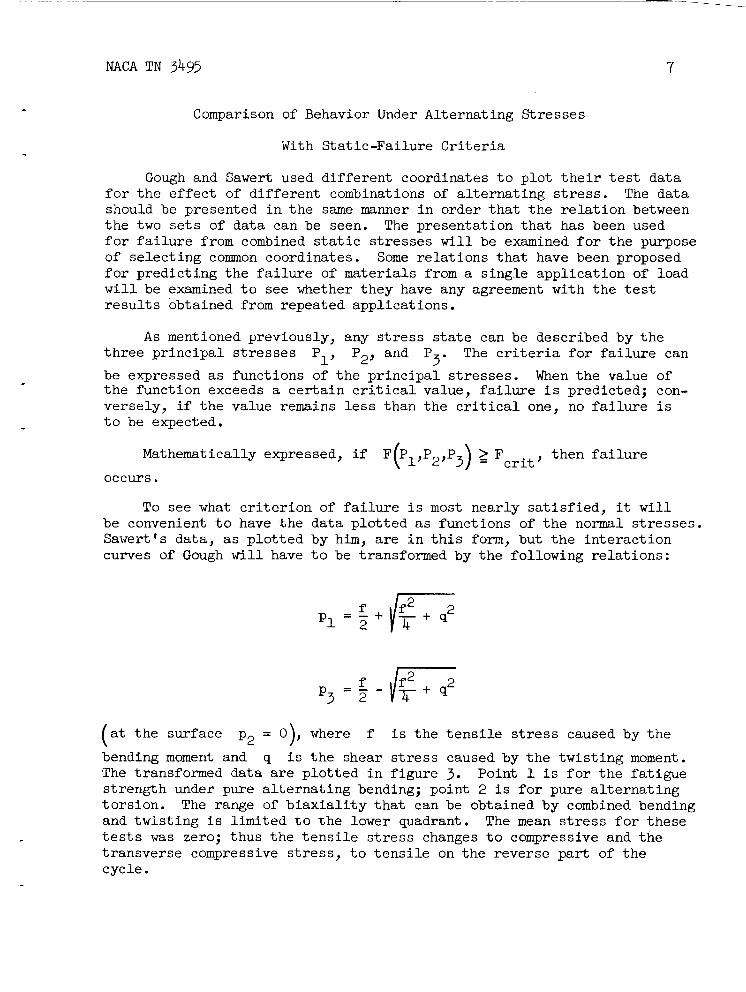
To see w h a t c r i t e r i o n of f a i l u r e i s most nearly satisfied, it w i l l be convenient t o have .the data p lo t ted as functions of t h e normal s t resses . Sawert's data, as p l o t t e d by him, are i n t h i s form, but t he in te rac t ion curves of Gough will have t o be transformed by t h e following re la t ions :
- f P 3 ' 3 -
( a t t h e surface p2 - - 0), where f
bending moment and q i s t h e shear The transformed data are p lo t ted i n
i s t h e t e n s i l e stress caused by the
stress caused by t h e twis t ing moment. f igure 3. Point 1 i s f o r t h e fatiwe
strength under pure a l t e r n a t i n g bending; point 2 i s f o r pure a l t e r n a t i n g tors ion . The range of b i a x i a l i t y t h a t can be obtained by combined bending and twis t ing i s l imited t o t h e lower quadrant. The mean stress f o r these tes ts was zero; thus t h e t e n s i l e s t r e s s changes t o compressive and t h e t ransverse compressive stress, t o t e n s i l e on t h e reverse p a r t of t h e cycle.

8 NACA TN 3495
Several c r i t e r i a f o r t h e f a i l u r e of polycrystal l ine s o l i d s from s t a t i c loads may now be examined t o see what cor re la t ion e x i s t s between these c r i t e r i a and t h e fa t igue- tes t data of Sawert and Gough presented i n f igures 2 and 3 .
The propert ies of mater ia ls and the conditions under which they are tested may d i f fe r grea t ly , and, a l so , failure may be considered t o occur when t h e r e i s e i t h e r excessive p l a s t i c deformation or rupture. These f a c t o r s cause t h e r e s u l t s of a p a r t i c u l a r s t a t i c tes t t o agree more c lose ly with one c r i t e r i o n than with t h e others; therefore , severa l c r i t e r i a have proved t o be usefu l i n t h e s t a t i c case. The c r i t e r i a are presented as functions of normal s t r e s s e s which become t h e pr inc ipa l stresses
t h e surface of t h e specimen i s t h e region considered, the pr inc ipa l stress normal t o t h e f r e e surface i s always zero.
P1, P2, and P when properly ordered ( P1 > P2 > P3). Since 3
The t h r e e most s ign i f icant s t r e s s c r i t e r i a f o r f a i l u r e from s t a t i c stresses may be simply described as follows:
(1) F a i l u r e may be predicted according t o the maximum-normal-stress c r i t e r i o n whenever t he p r i n c i p a l stress exceeds a c r i t i c a l value.
'1 > ' c r i t '
If then failure w i l l occur.
(2) Fa i lure may be predicted according t o t h e maximum-shear-stress c r i t e r i o n when t h e stress on any plane exceeds a c r i t i c a l value. theory of e l a s t i c i t y shows t h a t t h e maximum shear s t r e s s i s equal t o one- half t h e grea tes t difference between t h e p r i n c i p a l stresses, so t h e
p1 - p3 then failure c r i t e r i o n can be expressed as follows:
w i l l occur.
The
> 'wit, If 2
(3) Fa i lure may be predicted according t o t h e octahedral-shear- stress c r i t e r i o n i f t h e following funct ion exceeds a c r i t i c a l value, t h a t i s , i f
One i n t e r p r e t a t i o n of t h e physical significance of t h e octahedral- shear-s t ress c r i t e r i o n i s tha t it expresses t h e average of t h e e f f e c t s of slippage on d i f fe ren t planes and i n d i f f e r e n t d i rec t ions of a l l c r y s t a l s i n t h e aggregate, with t h e s l i p on any given plane being caused by resolved shear stress on t h a t plane (ref. 7 ) . adjoining c r y s t a l s upon each other i s a l s o considered but i s a f a c t o r of secondary importance. t i c d i s t o r t i o n must not exceed a constant value i s mathematically equiv- a l e n t t o expressing t h e octahedral-shear-stress c r i t e r i o n (ref. 8 ) .
The constraint of
Postulat ing t h a t t he p o t e n t i a l energy due t o e las -

!R NACA TN 3495
- Other c r i t e r i a of f a i l u r e have been discussei by Gough (ref.
The c r i t e r i a are superimposed on t h e tes t data i n figures 2 and 3 so t h a t t h e correspondence with experimental r e s u l t s can be examined. I n the upper quadrant a l l t h ree of t h e c r i t e r i a agree f a i r l y w e l l with t h e data. I n t h e lower quadrant t he data f o r steel are near t h e c r i t e r i a f o r maximum shear s t r e s s and octahedral shear stress, but t hey deviate sharply from t h e c r i t e r i o n f o r normal stress. There are, however, two d i f f i c u l t i e s with t h e data presented. A s i s usual i n f a t i g u e testing, it i s impract ical t o break enough specimens t o obtain a good s t a t i s t i c a l average, and t h e extent of " s i ze e f f ec t " i n Sawert 's work i s not known, s ince h i s specimens (because of t h e combined stresses he sought) were necessar i ly of various s i z e s and shapes. "Size e f f ec t " descr ibes t h e behavior i n which mater ia l i n a la rge par t appea r s , t o have a lower f a t igue s t rength than t h a t i n a smaller one (ref. 9). The da ta f o r s teel agree f a i r l y w e l l with both t h e maximum-shear and octahedral- shear c r i t e r i a , but t h e unavoidable s c a t t e r prevents determining which of these i s b e t t e r s a t i s f i e d . On the other hand, Cough's tests on cas t i r o n come nearer t o t h e c r i t e r i o n for normal stress than t o e i t h e r of t h e c r i t e r i a for shear stress; t h i s behavior i s discussed below i n detai l .
Another ind ica t ion of t h e stress c r i t e r i o n can be seen by examining t h e r a t i o of t h e reversed t o r s i o n a l f a t igue s t rength t o t h e reversed bending f a t igue s t rength f o r Cough's t e s t s presented i n t h e sec t ion "Experiments With Combined Alternat ing S t resses ." t h e two stress states on t h e pr inc ipa l -s t ress diagram ( f i g . 3) are:
The poin ts represent ing
(1) Pure bending stress, located on t h e absc issa
(2) Pure t o r s i o n a l stress, located on t h e l i n e passing through t h e o r ig in and b isec t ing the lower quadrant
The r a t i o s f o r t h e c r i t e r i a discussed above, as w e l l as f o r severa l add i t iona l ones, are:
Cr i te r ion of f a i l u r e
Constant maximum shear stress Constant maximum octahedral
Constant t o t a l s t r a i n energy Constant maximum pr inc ipa l
Constant maximum pr inc ipa l
shear
s t r a i n
stress
Max. shear stress i n t o r s i o n tes t Max. shear stress i n bending tes t
1.0
1.17 1.25
1.56
2.0

10 NACA TN 3495
Considering the normal s c a t t e r of f a t i g u e data, only t h e f irst two f i g - ures of t h e r a t i o s can be considered r e a l l y s ignif icant ; these r a t i o s a r e p lo t ted i n t h e bar diagram of figure 4, i n frequency of occurrence, i n 0.1 divis ions. The grea tes t frequency of f a i l u r e , consis t ing of t h e r a t i o s f o r s i x p a i r s of t e s t s , i s shown t o occur between 1.1 and 1.2, which ind ica tes t h a t t he data from these p a r t i c u l a r t e s t s i n the lower quadrant most near ly s a t i s f y t h e octahedral-shear c r i t e r i o n .
The scanty e x i s t i n g data do not give grounds f o r dis t inguishing whether the maximum-shear-stress c r i t e r i o n o r t h e octahedral-shear-stress c r i t e r i o n best f i t s t h e experimental r e s u l t s . Moreover, t h e constants can be chosen so tha t t h e two c r i t e r i a do not d i f f e r by more than +8 per- cent. Both sets of data indicate tha t a l t e r n a t i n g shear stress causes the f a t i g u e damage, t h e difference being caused only by the degree of averaging and by mutual constraint of the c rys ta l s . On the basis of present experimental knowledge, then, e i t h e r c r i t e r i o n can be j u s t i f i a b l y applied; t h e only evident choice between them i s the convenience of the mathematical expression i n any given case.
The i n t e r a c t i o n curves f o r fa t igue f a i l u r e induced by combined t o r - s i o n a l and bending s t r e s s e s for cas t i ron i n f igures l ( b ) and 3 and the r a t i o s of t o r s i o n a l t o bending fa t igue s t rength i n f igure 4 are very close t o what would be expected if t h e maximum pr inc ipa l stress were t h e cause of f a i l u r e ; however, t h e in te rac t ion curves f o r t h e other metals invest igated l i e i n t he region near t h e curves f o r a c r i t e r i o n of maxi- mum shear stress and t h a t of octahedral shear stress. If t h i s difference i n behavior ind ica tes tha t i n cas t i ron a completely d i f f e r e n t mechanism of f a t i g u e failure i s operative f r o m t h a t found i n other metals, the fundamental metal lurgical problem w i l l be severely complicated. A close examination w i l l be made i n an attempt t o resolve the two apparently d i f f e r e n t behaviors.
Microscopic observation of cas t i r o n reveals many flakes of graphite dispersed throughout the metal. much lower than tha t of the surrounding i ron c r y s t a l s . Therefore, the flakes of graphite car ry very l i t t l e stress i n compression, and because of t h e i r low strength they car ry even less i n tension. f a c t , l i k e holes i n t h e i ron s t ruc ture . The e f f e c t of these f lakes can
Graphite has a modulus of e l a s t i c i t y
They ac t , i n

NACA TN 3493 11
be seen by considering a simplified model of th ree holes or iented a t d i f f e r e n t angles as shown below:
t u 2
Sketch 1 When al i s applied, regions A1 and A2 at t h e edge of one f l a k e
w i l l be much more highly s t ressed than any other region because of t h e e l a s t i c stress concentration caused by t h e hole. Regions B1 and B2 Will a l s o be more highly s t ressed than t h e average but s t i l l considerably less than A1 and A2. Regions C 1 and C 2 around t h e edge of t h e f l a k e longi- t u d i n a l t o t h e applied stress w i l l be s t ressed even less than t h e aver- age f o r t he bulk of t h e material. The regions most highly s t ressed by the t ransverse stress stressed very l i t t l e . The e l a s t i c analysis of cracks or iented at d i f - f e r e n t angles under several combinations of stress i s presented i n appendix A . The analysis shows t h a t t h e sum of t h e e f f e c t s caused by t h e t ransverse and longi tudinal s t r e s s e s together a t cracks or iented at angles between t h a t of AlA2 and CLC2 i s l e s s than t h a t caused by them individual ly a t A1 and A2 or C1 and C2, except f o r t h e range of combinations of applied s t r e s s e s where t h e t ransverse stress approaches a value equal t o t h e longi tudinal one and then t h e combined e f f e c t i s s l i g h t l y grea te r a t one or ien ta t ion than t h e i s o l a t e d individual e f f e c t s a t other or ientat ions. Thus t h e grea tes t damage from t h e two stresses i s local ized a t d i f fe ren t points , which causes t h e i r e f f e c t s t o be independent. The independence of t h e e f f e c t s of t h e p r i n c i p a l stresses i s t h e e s s e n t i a l c h a r a c t e r i s t i c of t h e behavior t h a t indicated t h a t t h e pr inc ipa l -s t ress c r i t e r i o n might be operative; however, t h e independence can be explained by t h e l o c a l i z a t i o n of t h e damage. i s given as t o which of t h e stress c r i t e r i a i s appl icable i n t h e highly s t ressed microscopic regions; it could be a shear-s t ress c r i t e r i o n .
a2 a r e C1 and C2, while regions A1 and A2 are
Thus no evidence

12 NACA TN 3495
I n a l l cases examined i n which a maximum-normal-stress c r i t e r i o n best f i t t e d t h e data , t he re has been strong reason t o bel ieve t h a t f l akes of graphi te or other f l ake l ike inclusions were present i n t h e mater ia l . Turner 's t e s t s on annealed hypereutectoid steel ( r e f . 10) showed t h a t a maximum-normal-stress c r i t e r i o n w a s more near ly s a t i s f i e d than a maximum- shear-s t ress c r i t e r i o n . Graphite f l akes may w e l l have been present i n t h e s t e e l he used, for Sisco (ref. 11) mentioned t h a t it w a s noticed many years ago t h a t occasionally, i n annealing high-carbon s t e e l , free carbon (graphi te ) would form. such flake inclusions t o cause t h e e f f e c t , f o r Thum and Petersen (ref. 12) s tudied t h e e f f e c t of g raph i t i c carbon i n cas t i ron on t e n s i l e and f a t igue s t rength and concluded t h a t t h e f a t igue s t rength depends ch ie f ly upon t h e notch e f f e c t of t h e p a r t i c l e s of graphi te and t h a t t h i s e f f ec t i s great even when l i t t l e graphi te i s present , as demonstrated by t h e f a c t t h a t t h e f a t igue s t rength decreased qui te slowly as t h e amount of graphi t ic carbon w a s increased.
Evidently, too, it would not take many
These considerat ions indicate , then, t h a t , although some mater ia ls , p a r t i c u l a r l y cas t i ron, seem t o f i l l near ly a maximum-normal-stress c r i t e r i o n , t h e f a i l u r e i s not necessar i ly caused by normal stresses; thus it may have s t a r t e d from damage caused by a l t e rna t ion of shear stresses i n t h e highly s t r e s sed region at the edge of a f l a k e of graphi te . Therefore, whatever theory explains t h e f a t igue f a i l u r e i n t h e more homo- geneous metals may a l s o explain t h e f a i l u r e of cas t i ron and other metals, which have previously seemed t o be exceptions.
Ef fec t of S t a t i c S t r e s s Superimposed on Alternat ing S t r e s s
From t h e above determination t h a t t e s t data and shear c r i t e r i a do agree, it seems t h a t t h e component of t h e a l t e rna t ing s t r e s s f i e l d t h a t causes f a t igue damage i s the shear s t r e s s . To w h a t extent the permis- s i b l e amplitude of a l t e rna t ing s t r e s s depends upon t h e s t a t i c s t r e s s must be examined i n d i f f e ren t stress combinations i n an attempt t o i so- la te t h e component or combination of components of t h e s t a t i c stress operat ive i n the r e l a t i o n . Experiments on t h e influence w i l l be examined:
(1) The e f f e c t of s t a t i c tens ion on t h e permissible amplitude of a l t e rna t ing a x i a l stress and t h e e f f e c t of s t a t i c compression on t h e per- missible amplitude of a l t e r n a t i n g a x i a l stress ( f i g . 5 )
(2) The e f f e c t of s t a t i c t o r s ion on t h e permissible amplitude of a l t e rna t ing t o r s i o n ( f i g . 6 )
( 3 ) The e f f e c t of s t a t i c t o r s ion on the permissible amplitude of a l t e rna t ing bending ( f i g . 7)

NACA TN 3493 13
(4) The e f f e c t of s t a t i c tens ion on the permissible amplitude of a l t e rna t ing to r s ion and t h e e f f ec t of bending on t h e permissible ampli- tude of a l t e r n a t i n g to r s ion ( f i g . 8)
Figure 5 shows t h e e f f e c t of mean a x i a l stress on t h e permissible amplitude of a l t e rna t ing a x i a l stress f o r some common mater ia l s w i t h f a t igue l i v e s of lo6 t o lo7 cycles. Quite c l ea r ly , t h e amplitude of a l t e rna t ing stress i s decreased by the t e n s i l e mean s t r e s s and i s increased by t h e compressive mean stress. The choice of coordinates was not made i n order t o imply a dependence of t h e slope on t h e y i e ld s t rength but as a convenient way of presenting t h e group of separate curves and yet emphasizing t h e behavior i n t h e region below t h e yield; moreover, Nishihara and Sakurai (ref. 13) have shown i n some cases t h a t t he re i s a dependence of t h e slope on t h e t r u e rupture s t rength.
Only by c r i t i c a l s e l ec t ion of t h e data f o r t h e compressive region w a s it possible t o p l o t t h e considerable slope shown; i f a l l invest iga- t i o n s were included, t h e t r end would be hor izonta l (ref. 14) . t echnica l d i f f i c u l t i e s of applying a t r u e a x i a l compressive load are considerable, and it is l i k e l y t h a t uncontrolled bending stresses have inval idated some tests. Those c i t e d here w e r e chosen because t h e tech- niques employed seem t o insure t r u e a x i a l loading.
The
I n Nishihara and Sakurai ' s t e s t s , t h e load was transmit ted t o t h e
Thus t h e exact pos i t ion of t h e force was known and it could be specimen through an arrangement containing a b a l l r e s t i n g on a f la t sur- face. centered accura te ly on the ax i s of t h e specimen.
Newmark and coworkers (ref. 17) and ROE and Eichinger (ref. 5 ) used specimens with ca re fu l ly squared ends i n attachments that made t h e gripping heads remain p a r a l l e l and concentric during t h e stress cycle. They a l s o checked t h e a x i a l i t y by means of e l e c t r i c s t r a i n gages.
The r e l a t i o n i s l i n e a r i n t h e region where maximum stress does not exceed t h e y i e ld s t rength. If only f a t igue rupture (not y ie ld ing) i s considered t o be failure, t h e l i n e a r pa r t of t h e curve has been shown t o extend beyond the y ie ld s t rength and then t o t u r n sharply t o t h e abscissa, i n t e r sec t ing it at t h e point of s t a t i c rupture s t rength (ref. 5 ) .
Figure 6 shows t h e e f f e c t of s t a t i c t o r s ion on t h e permissible ampli- tude of a l t e rna t ing tors ion . The great number of tests p lo t t ed gives conclusive proof t h a t s t a t i c t o r s i o n has no e f f e c t on t h e permissible

14 NACA TN 3495
range of a l t e r n a t i o n so long a s t h e maximum to r s iona l stress i s below t h e y ie ld strength.*
i
Figures 7(a) and 7(b) show the ava i lab le data on t h e e f f e c t of s t a t i c t o r s ion superimposed on a l t e rna t ing bending stresses. f e w tes ts p lo t ted , it seems t h a t bending f a t igue s t rength i s not a f fec ted u n t i l s t a t i c t o r s ion exceeds the t o r s i o n a l y i e ld strength by almost
From t h e
70 percent. 3
Figure 8 shows the only two t e s t s known t o t h e author of t he e f f e c t of t e n s i l e s t a t i c s t r e s s on t h e permissible amplitude of a l t e rna t ing tors ion . I n one tes t the t e n s i l e s t r e s s was produced by bending, while i n t h e other it was produced by an a x i a l load. The l i n e a r dependence of t h e amplitude of a l t e rna t ing to r s ion upon t h e applied s t a t i c t e n s i l e stress is similar t o that shown i n f igu re 5, which presents the e f f e c t of s t a t i c a x i a l stress on the amplitude of a x i a l stress.
It was infer red f r o m the agreement of the f a t igue tests under com- bined a l t e rna t ing stresses w i t h the shear -s t ress c r i t e r i a t h a t t h e alterna- t i o n of shear stresses causes the f a t igue damage and t h e r e su l t an t fail- ure. The preceding presentat ion of the e f f e c t of d i f f e r e n t s t a t i c s t r e s s e s on t h e permissible amplitude of a l t e rna t ing stress was made i n an attempt t o i s o l a t e the e f f ec t ive parameters and revea l the func t iona l r e l a t i o n of t h e s t a t i c stress t o the permissible amplitude of a l t e r n a t i n g stress. The behavior i s summarized i n figure 9.
*Plot t ing f a t igue t e s t s taken a t only one mean stress f o r materials having d i f f e ren t y i e ld strengths could give a deceptive hor izonta l l i n e because the absc issa i s t h e r a t i o of t he maximum shear stress t o the y i e ld strength; but examination of a s e r i e s of t e s t s on one ma te r i a l i n which the maximum stress was varied appreciably, f o r example, Ludwik and Krystof 's t e s t s on Siemens-Martin s t e e l ( r e f . 16) o r Moore and L e w i s ' tests on duralumin ( r e f . l7), shows t h a t t he observation i s a va l id one and not t he r e s u l t of the choice of the coordinate.
presented some experiments t h a t show tha t s t a t i c t o r s i o n does influence the a l t e rna t ing bending strength; these data contradict those of Lea and and Budgen (ref. 19) and of Ono ( r e f . 20). The sources of h i s informa- t i o n were t h e masters theses of Nimhanminne (ref. 21) and Hui t t ( r e f . 22) a t t he Bat tersea Polytechnic I n s t i t u t e . reveals t h a t t h e i r "fat igue strength" w a s not obtained by f r a c t u r e of a series of specimens but w a s defined as that s t r e s s a t which nonlinear def lec t ion occurs under increasing a l t e rna t ing s t r e s s . This " fa t igue strength" may be usefu l i n p a r t i c u l a r designs where nonlinear def lec t ion can be construed as f a i l u r e , but it i s not the conventional f a t igue s t rength and should not be compared with that of the other inves t iga tors . Although it was not mentioned, t h e device used t o apply the s t a t i c t o r - s iona l stress appears inadvertent ly t o apply a s t a t i c bending stress. This could also contr ibute t o the observed anomalous behavior.
3Davies, i n a discussion of t h e paper of Gough and Pol la rd (ref. 18),
Examination of these theses

NACA TN 3495
Because t h e a l t e r n a t i o n of shear s t r e s s seems t o cause the f a t igue failure, the s t a t i c stresses on the planes of grea tes t a l t e r n a t i o n of shear w i l l be examined. The planes are iden t i f i ed on the specimens i l l u s t r a t i n g t h e stress state and are shown magnified i n the center column together wi th the s t a t i c s t r e s s e s t h a t a c t on them ( f i g . 9 ) .
A simple co r re l a t ion appears between the sum of t h e normal s t a t i c stresses on these planes and the va r i a t ion of t h e permissible amplitude of a l t e rna t ing stress. For example, examination of stress state (l), t h e e f f e c t of tens ion on the amplitude of shear, shows t h a t , when t h e sum N1 + N2 increases , the amplitude i s decreased. When t h e sum i s zero, as i n combination ( 3 ) , t h e e f f e c t of t o r s ion on the amplitude of bending, t h e permissible amplitude of a l t e rna t ing stress i s independent of the s t a t i c stress.
The sum of the normal s t r e s s e s on orthogonal planes has been shown i n the theory of e l a s t i c i t y t o be independent of the o r i en ta t ion of the planes t o the stress f i e l d (ref. 23). invariant of t h e stress tensor . ) Therefore, t he r e l a t i o n can be expressed more general ly as a funct ion of t h e sum of any other convenient orthogonal normal stresses ins tead of as t h e sum of the n o m 1 stresses on the planes of maximum a l t e r n a t i n g shear.
(The sum is ca l l ed t h e first
A review of the data presented i n f igu res 5 , 6, 7, and 8 w i l l show t h a t a l i n e a r funct ion c lose ly approximates t h e e f f e c t of s t a t i c stress on the permissible amplitude of a l t e rna t ing stress i f the stresses do not exceed the y i e ld s t rength. Because of the s c a t t e r inherent i n f a t igue tests, a higher order of approximation would not be j u s t i f i e d . A general stress c r i t e r i o n may be postulated t h a t agrees with a l l t h e above data and w i t h t h e combined-alternating-stress data t h a t were pre- viously presented. I n t h i s expression it is convenient t o use the octahedral shear s t r e s s , because it i s independent of the o r i en ta t ion of t he orthogonal stress coordinates i n t h e same way tha t t he sum of t h e orthogonal normal stresses i s . The general c r i t e r i o n combines the shear c r i t e r i o n f o r combined a l t e rna t ing stress with t h e l i n e a r r e l a t i o n of the amplitude of a l t e rna t ing stress t o the s t a t i c stress. T h i s gen- eral c r i t e r i o n may be expressed as
and p are the amplitudes of the a l t e r n a t i n g p r inc ipa l where P1’ P2’ 3 stresses, Sx, sy, and S, are t h e orthogonal s t a t i c stresses, A I s
a constant f o r the material proport ional t o t h e reversed f a t igue s t rength, and a gives t h e va r i a t ion of t h e permissible range of stress with s t a t i c stress; A and a are a l s o dependent on the number of cycles t o failure.

16 NACA TN 3495
The term on the l e f t must not exceed t h a t on t h e r i g h t o r failure w i l l occur before t h e desired l i fe t ime. The amplitudes of t h e a l t e r n a t i n g pr inc ipa l s t r e s s e s do not have t o be ordered teriori because t he i r differences a r e squared i n it.
p1 > p2 > p3 i n the c r i -
Two t e n s i l e fa t igue tests, one with a zero mean stress and t h e other with a high pos i t ive mean stress (but not so high t h a t t h e maximum s t r e s s exceeds t h e y ie ld s t rength) , could be conveniently used t o determine t h e two constants.
Expressed more b r i e f l y i n terms of t h e tensor invariants , t h e square root of t h e second s t r e s s invariant of t h e a l t e r n a t i n g stress i s a l i n e a r funct ion of t h e f irst invariant of t h e s t a t i c stress
J 112 I B - PJLstatic 'alternating -
where B and p d i f f e r f r o m t h e previously defined A and a by a mul t ip l ica t ive constant.
A graphical representat ion of t h e c r i t e r i o n for t h e f a i l u r e of a body a t a f r e e surface i s shown i n f igure 10. Early paragraphs of t h i s report give some reasons why consideration of t h e surface is of more i n t e r e s t than consideration of t h e i n t e r i o r . A t a f r e e surface one p r i n c i p a l s t r e s s i s zero; therefore t h e c r i t e r i o n can be p l o t t e d on a two-dimensional space of t h e other two pr inc ipa l stresses. The more pos i t ive t h e sum of t h e s t a t i c stresses, t h e smaller t h e e l l i p s e . The p l o t appears as a series of "concentric" e l l i p s e s , t h e s i z e of which i s dependent upon t h e sum of t h e s t a t i c normal stresses. The shape of t h e e l l i p s e s ( r a t i o of axes) w a s f ixed by t h e i n s e r t i o n of t h e octahedral shear i n t o t h e c r i t e r i o n .
Another ax is orthogonal t o t h e two of f i g u r e 10 i s needed f o r t h e representat ion of t h e c r i t e r i o n when it i s applied t o t h e i n t e r i o r of a body. The failure surface i n t h i s space i s a c y l i n d r i c a l surface with
generators having t h e d i r e c t i o n a l cosines sect ing the planes of t h e axes i n t h e e l l i p s e s shown i n t h e two-dimensional representat ion ( r e f . 24).
116, 116, and 116 i n t e r -
Comparison of Proposed Cr i te r ion With
Complex Combinations of S t ress
Gough's tests.- Gough has performed some tes ts t h a t may be used t o support t h e general c r i t e r i o n (ref. 1). The tests w e r e conducted not
-
3R NACA TN 3495 17
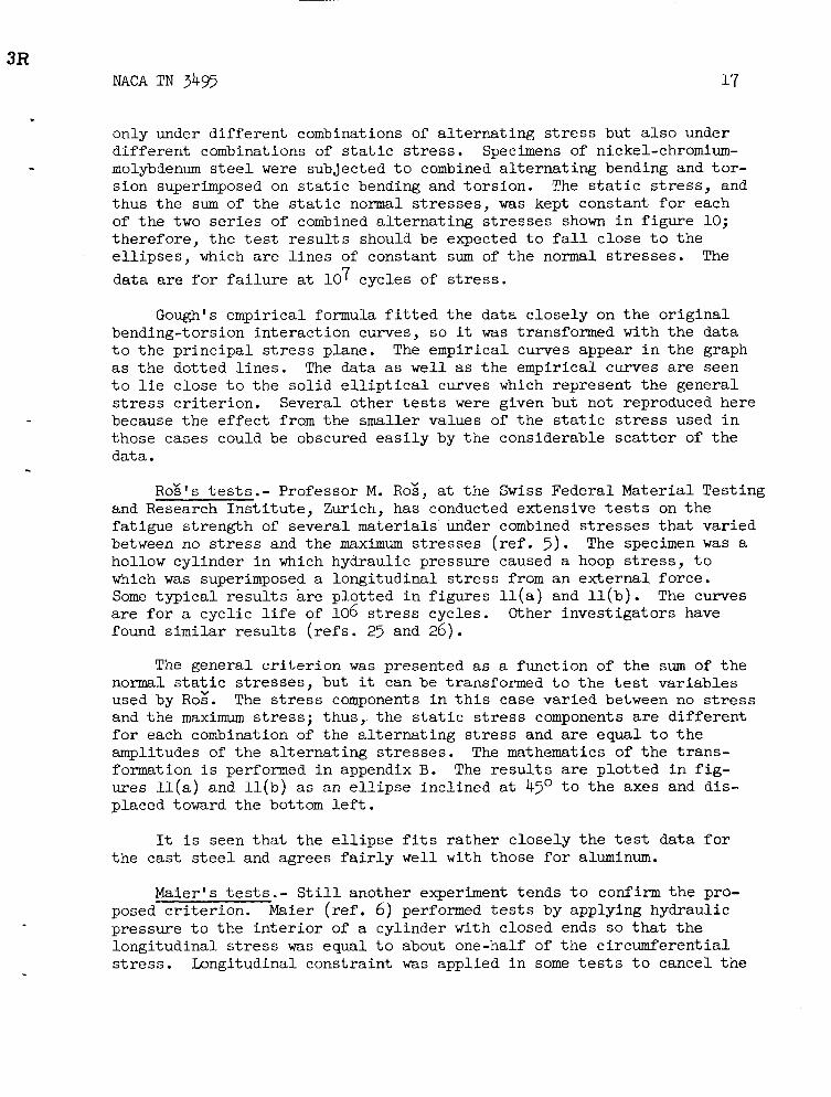
only under d i f fe ren t combinations of a l t e r n a t i n g s t r e s s but a l s o under d i f fe ren t combinations of s t a t i c stress. Specimens of nickel-chromium- molybdenum s t e e l were subjected t o combined a l t e r n a t i n g bending and t o r - s ion superimposed on s t a t i c bending and tors ion . The s t a t i c stress, and thus t h e sum of t h e s t a t i c normal stresses, w a s kept constant f o r each of t h e two series of combined a l t e r n a t i n g s t r e s s e s shown i n f igure 10; therefore , t h e tes t r e s u l t s should be expected t o f a l l c lose t o t h e e l l i p s e s , which are l i n e s of constant sum of t h e normal stresses. The data are f o r f a i l u r e a t 10 7 cycles of stress.
Gough's empirical formula f i t t e d t h e data c lose ly on t h e o r i g i n a l bending-torsion in te rac t ion curves, s o it was transformed w i t h t h e data t o t h e p r i n c i p a l s t r e s s plane. as t h e dotted l i n e s . The data as w e l l as t h e empirical curves are seen t o l i e c lose t o t h e s o l i d e l l i p t i c a l curves which represent t h e general s t r e s s c r i t e r i o n . Several other tes ts were given but not reproduced here because t h e e f f e c t from t h e smaller values of t h e s t a t i c stress used i n those cases could be obscured e a s i l y by t h e considerable s c a t t e r of t h e data.
The empirical curves appear i n t h e graph
ROE'S t e s t s . - Professor M. Roz, a t t h e Swiss Federal Material Testing and Research I n s t i t u t e , Zurich, has conducted extensive t es t s on t h e fa t igue s t rength of several mater ia ls under combined s t r e s s e s t h a t var ied between no stress and t h e maximum s t r e s s e s (ref. 3 ) . hollow cylinder i n which hydraulic pressure caused a hoop s t r e s s , t o which w a s superimposed a longi tudinal s t r e s s from an ex terna l force. Some t y p i c a l r e s u l t s a r e p lo t ted i n figures l l ( a ) and l l ( b ) . a r e f o r a cycl ic l i f e of 106 s t r e s s cycles. found s i m i l a r r e s u l t s (refs. 23 and 26).
The specimen was a
The curves Other inves t iga tors have
The general criterion w a s presented as a funct ion of t h e sum of t h e normal s t a t i c stresses, but it can be transformed t o t h e t es t var iables used by ROE. and t h e maximum s t r e s s ; thus, t he s t a t i c stress components are d i f fe ren t f o r each combination of t h e a l t e r n a t i n g s t r e s s and are equal t o t h e amplitudes of t h e a l t e r n a t i n g s t r e s s e s . The mathematics of t h e t rans- formation i s performed i n appendix B. The r e s u l t s are p l o t t e d i n f i g - ures l l ( a ) and U ( b ) as an e l l i p s e incl ined at 4 5 O t o t h e axes and d is - placed toward t h e bottom l e f t .
The stress components i n t h i s case var ied between no stress
It i s seen tha t t h e e l l i p s e f i t s r a t h e r c lose ly t h e t es t data f o r the cas t s t e e l and agrees f a i r l y w e l l w i t h those f o r aluminum.
Maier's t e s t s . - S t i l l another experiment tends t o confirm t h e pro- posed c r i t e r i o n . Maier (ref. 6) performed tests by applying hydraulic pressure t o t h e i n t e r i o r of a cylinder with closed ends so t h a t t h e longi tudinal stress was equal t o about one-half of the circumferent ia l stress. Longitudinal constraint was applied i n some tes ts t o cancel t h e

18 NACA TN 3495
longi tudina l stress, so t h a t only circumferent ia l s t r e s s w a s present . The stress cycle w a s between zero s t r e s s and maximum stress ( the same as Roz's), thus making the mean stress ( the s t a t i c stress) equal t o the amplitude of the a l t e rna t ing s t r e s s . Maier's experiments showed that t h e cons t ra in t had no e f f e c t on circumferent ia l fa t igue s t rength .
I n appendix B, t h e general c r i t e r i o n i n which the permissible ampli- tude of octahedral shear s t r e s s i s a l i n e a r funct ion of t he s t a t i c stress i s transformed f o r t h e stress cycle, which var ies from zero t o maximum. If one i n s e r t s i n t o the transformed c r i t e r i o n a f a i r l y t y p i c a l value f o r t h e zero-to-compression f a t igue s t rength, t h a t is , a value one and one- half t i m e s as grea t as t h a t f o r zero-to-tension fa t igue strength, then it is found t h a t t h e superimposition of t h e circumferent ia l stress on a longi tudina l stress equal t o one-half t h e circumferent ia l results i n a predicted f a t igue s t rength no d i f f e ren t from t h a t found where no longi- t u d i n a l stress i s applied. if a l i n e were passed p a r a l l e l t o the abscissa through t h e point of i n t e r - sec t ion of t h e e l l i p s e w i t h t he ordinate (ul = 0,
i n t e r s e c t t h e e l l ipse again a t u = 14, u = 28. Thus, Maier's data
agree c lose ly w i t h t h e general c r i t e r i o n .
This can a l s o be seen i n f igu re l l ( a ) where,
a2 = 28), it would
1 2
Maier in te rpre ted h i s t e s t s t o ind ica te t h a t the maximum-shear c r i t e r i o n f o r s t a t i c failure applied instead of the octahedral, because t h e maximum-shear c r i t e r i o n i s independent of t he intermediate stress ( i n t h i s case t h e longi tudina l ) and the octahedral c r i t e r i o n i s a function of the intermediate s t r e s s . Certainly ne i ther t he simple octahedral c r i - t e r i o n nor a simple maximum-shear c r i t e r i o n tha t contains only one set of stresses can be appl ied t o a case where s t a t i c s t r e s ses are superimposed upon the a l t e r n a t i n g ones, because the c r i t e r i o n must be a funct ion of both the a l t e r n a t i n g and s t a t i c s t r e s ses .
Se lec t ion of t e s t var iab les f o r complex-stress tes ts . - Attent ion should be paid t o t h e se l ec t ion of t h e tes t parameters f o r f a t igue tes ts under combined stresses, s o t h a t the r e s u l t s w i l l have as grea t an appl i - c a b i l i t y as possible f o r t h e pred ic t ion of behavior.
One choice of parameters would be t o f i x t h e r a t i o of minimum t o maximum s t r e s s f o r t he a l t e rna t ing p r inc ipa l s t r e s s e s f o r each series of stress combinations. Assuming t h a t t he general stress c r i t e r i o n pro- posed does pred ic t t he behavior, i t s transformation t o t h i s set of param- e t e r s i s calculated i n t h e appendix f o r a given cyc l ic l i f e and appears graphica l ly i n figure 12(a).
A s e r i e s of combined-alternating-stress tes ts could be performed with another s e l ec t ion of parameters i n which the s t a t i c stress was main- t a ined constant f o r each combination of t he s e r i e s and changed f o r each series. These t e s t s would appear as the e l l i p s e s shown i n figure 12(b) .

NACA TN 34.95 19
F The two methods f o r obtaining and presenting t h e information are equally good so long as both pr inc ipa l stresses have t h e same r a t i o G f minimum t o maximum stress; however, i f t h e r a t i o i s d i f f e r e n t , then the f irst p lo t has no u t i l i t y . The usefulness of t h e second method i s even grea te r because t h e e l l i p s e s are not only l i n e s of constant s t a t i c stress but l i n e s of constant sum of t h e orthogonal s t a t i c stress components. Thus, it would be more general t o take data by t h e second method using t h e s t a t i c stress as a parameter, holding it constant f o r individual a l t e r n a t i n g stress combinations and changing it from one s e r i e s t o t h e next.
Limitations of c r i te r ion . - The general c r i t e r i o n proposed i s not useful as a design c r i t e r i o n f o r cas t iron, hypereutectoid steels, or other metals t h a t a l s o might contain f lake l ike inclusions o r microcracks; t h e impossibi l i ty of obtaining de ta i led information concerning t h e cracks and inclusions prevents t h e appl icat ion of t h e general c r i t e r i o n . and others showed t h a t a maximum-normal-stress c r i t e r i o n i s applicable t o the aggregate (see ref. 1).
Gough
Also, t h e a x i a l fa t igue s t rength of cas t i r o n i s not a l i n e a r func- t i o n of t h e s t a t i c stress; compressive stress improves t h e fatigue strength more than t e n s i l e stress reduces it. The r a t h e r complicated r e l a t i o n w a s shown by Ro: and Eichinger (ref. 2).
Discussion of Previously Proposed C r i t e r i a f o r Fatigue Fa i lure
An attempt w a s made by Bailey ( r e f . 27) t o predict t h e e f f e c t s of combined a l t e r n a t i n g and s t a t i c stresses. A t t h a t time, 1917, most of t he data presented i n t h e der ivat ion of t h e general c r i t e r i o n had not been taken. Bailey decided from examination of Stanton and Batson's r e s u l t s (ref. 28) from tes ts under a l t e r n a t i n g bending and a l t e r n a t i n g t o r s i o n t h a t " i n t h e absence of evidence t o the contrary, then, t h e most reasonable assumption t o make i n pursuing t h e object i n view i s that under a l l combinations of bending moment and twis t ing moment, e i t h e r var iable o r constant i n magnitude, the f a i l u r e of a d u c t i l e material i s by shear, uninfluenced by t h e presence of normal stress on t h e plane of failure . "
The statement t h a t failure of a d u c t i l e mater ia l i s by shear agrees with t h e l a t e r data; however, examination of data summarized i n figure 9 shows t h a t t h e normal component of t h e s t a t i c stress did influence the permissible amplitude of a l t e r n a t i n g shear stress.
Bailey's method of analysis might be judged inva l id because one of t h e basic assumptions, t h a t i s , t h a t s t a t i c normal stresses are of no influence, has been refuted; however, it deserves c lose inspection because, with h i s analysis , he made t h e predict ion t h a t s t a t i c t o r s i o n

20 NACA TN 3493
below a c e r t a i n l i m i t would have no e f f e c t on a l t e r n a t i n g bending, which 1
w a s substant ia ted by Ono's t e s t r e s u l t s ( r e f . 20). when applied t o t h e e f f e c t of s t a t i c t o r s i o n on a l t e r n a t i n g t o r s i o n ( r e f . 29) did not predict t h e known r e s u l t s presented i n figure 6.
However, t h e analysis
Other c r i t e r i a f o r f a i l u r e under combined a l t e r n a t i n g and s t a t i c They are a l l based upon t h e s t r e s s e s are summarized i n reference 30.
"Soderberg s t r a i g h t l i n e l aw," which r e l a t e s t h e permissible maximum t o t h e absolute value of t h e mean stress s t r e s s I s m i : 'max
where p i s defined as t h e r a t i o of t h e reversed fa t igue s t rength Se t o the y i e l d s t rength Syp.
The maximum-normal-stress c r i t e r i o n as presented i n t h e present report cons is t s of i n s e r t i n g each of t h e three pr inc ipa l stresses i n t o t h e Soderberg law- to see i f t h e grea tes t p r inc ipa l s t r e s s i s less than t h e expression on t h e right.
For t h e maximum-shear c r i t e r i a , t h e Soderberg l a w i s rewri t ten i n terms of t h e shear s t r e s s e s , and t h e m a x i m u m shear stress i s l imited:
I n t h e t h i r d c r i t e r i o n , t h e value of t h e d i s t o r t i o n energies cor- responding t o t h e maximum stress, mean stress, and t h e reversed fa t igue s t rength are inser ted i n t o t h e Soderberg l a w i n place of t h e respect ive s t r e s s e s .
The Soderberg l a w expresses t h e maximum of t h e stress cycle as a funct ion of t h e absolute value of t h e mean s t ress ; thus, it indicates t h a t a s t a t i c compressive stress reduces t h e permissible range of al ter- nating stress as much as a s t a t i c t e n s i l e stress does. The data pre- sented i n figure 3 show t h a t a s t a t i c compressive stress improves t h e permissible range of a l t e r n a t i n g stress instead of reducing it. a l l th ree of t h e above c r i t e r i a , f o r t h e case of simple a l t e r n a t i n g a x i a l stress superimposed upon a s t a t i c stress, reduce t o t h e statement of t h e Soderberg l a w , which has been shown not t o agree with t h e
Since

NACA TN 34% 21
experimental data, t h e i r v a l i d i t y i s questioned. The c r i t e r i a do have u t i l i t y i n very conservative machine-design pract ice , but they mask t h e behavior present i n t h e fa t igue phenomenon.
EXPERIMENTAL CHECK ON PROPOSED CRITERION
Choice of Experimental Test
I n t h e process of formulating t h e general stress c r i t e r i o n f o r fa t igue , t e s t r e s u l t s f o r various combinations of a l t e r n a t i n g s t r e s s e s were examined and a l s o those f o r combinations of simple s t a t i c s t r e s s e s with simple a l t e r n a t i n g s t resses . Examination of t h e t es t r e s u l t s sum- marized i n f i g u r e 9 reveals one notable absence, t h e e f f e c t of s t a t i c compressive stress on a l t e r n a t i n g tors ion. T e s t r e s u l t s w e r e presented f o r t h e e f f e c t of s t a t i c t e n s i l e stress on t h e permissible range of a l t e r n a t i n g t o r s i o n i n f igure 8 and were extrapolated i n t o t h e compres- s ive region; t h e dotted l i n e s show t h e an t ic ipa ted behavior.
It was decided t o augment t h e ex is t ing data and t o t es t t h e c r i t e r i o n by an experimental program. and manufactured f o r t h e t e s t i n g of two s e r i e s o f ' specimens, one with a l t e r n a t i n g t o r s i o n only and t h e other with s t a t i c compressive stress superimposed on t h e a l t e r n a t i n g tors ion .
Specimens and a s t r e s s i n g system were designed
Material
The material used f o r t h e tes t was 6061-~6 (61s-~6) aluminum a l loy . T h i s material w a s chosen f o r t h e t es t because i t s r a t i o of y ie ld s t rength t o f a t i g u e s t rength i s high; t h e occurrence of yielding from t h e combi- nation of t h e applied t o r s i o n and compressive stresses would complicate t h e analysis of t h e r e s u l t s . The nominal propert ies ( r e f . 31) of t he mater ia l are :
Ultimate t e n s i l e s t rength, p s i . . . . . . . . . . . . . . . . 43,000 Yield s t rength, 0.2-percent o f f s e t , p s i . . . . . . . . . . . . 40,000 Elongation i n 2 in . , percent . . . . . . . . . . . . . . . . . . . 17 B r i n e l l hardness, 500-kg load, 10-mm b a l l . . . . . . . . . . . . . 95 Shear s t rength, p s i . . . . . . . . . . . . . . . . . . . . . . 30,000
Reversed bending fatigue strength . . . . . . 17,000 p s i at lo7 cycles
The measured hardness was 89, which, when compared with t h e nominal value of 95, indicates t h a t t h e y i e l d s t rength might a l s o be s l i g h t l y less than t h e nominal.

22 NACA TN 3495
Four specimens, approximately 3/4 inch square, w e r e machined from the width of 1- by 4-inch r o l l e d p la te .
Specimen
The specimen used t o determine t h e e f f e c t of s t a t i c compressive stress on a l t e r n a t i n g t o r s i o n i s shown i n a drawing ( f i g . 13) and i n a photograph ( f i g . 14) . The t e s t sections are t h e two c y l i n d r i c a l sur- faces t h a t are separated by t h e short square length i n t h e center. a l t e r n a t i n g twis t ing moment i s applied by t h e torque lever t h a t clamps on t h i s center section. The surfaces have a square cross sect ion so t h a t they can be clamped t o r e s i s t t h e t o r s i o n a l moment. area of t h e tes t sect ion i s less than t h a t of t h e clamped surfaces so t h a t failure occurs i n the t e s t sect ion and not a t a region under t h e influence of the unknown clamping s t resses . The device used t o apply t h e s t a t i c compressive s t r e s s requires t h a t a longi tudinal hole be bored through t h e specimen.
The
The cross-sectional
For t h e convenience of holding t h e specimen i n a c o l l e t chuck during machining, both ends of t h e specimen are turned t o a diameter of 3/4 inch for a 1/2-inch length.
The square clamped surfaces were t rued by scraping and d r a w f i l i n g ; t h e i r accuracy w a s checked by t h e t r a n s f e r of bluing from a surface p l a t e .
The f inal l a t h e cut w a s l e s s than 0.005 inch and made w i t h a sharp Minnesota Mining and Manufacturing Co. Wetordry No. 240-, 32O-,
Every specimen w a s polished circumferentially i n a l a t h e and
t o o l . 400-, and 600-grit polishing paper was used with water t o pol i sh t h e t e s t surface. then longi tudinal ly by hand with each g r i t . were removed each time by t h e next f i n e r paper, so t h a t no scratches exis ted on the polished surface coarser than w e r e l e f t by the f i n a l paper, which had No. 600 g r i t .
The longi tudinal scratches
Apparatus
S t a t i c compressing device. - The assembled device f o r applying t h e s t a t i c compressive s t r e s s i s presented i n cross sect ion i n f igure 15 and t h e disassembled components a r e shown i n a photograph ( f i g . 14) . stress rod passes through t h e B e l l e v i l l e spring assembly and t h e hollow specimen. The spring and t’ie specimen are compressed by t ightening t h e hexagonal nut on t h e drawscrew. during t h e t ightening of t h e nut by a key t h a t f i t s i n t o a keyway on the drawscrew. All t h e p a r t s are highly s t ressed, necess i ta t ing t h e use of hardened t o o l s t e e l s . The B e l l e v i l l e springs were machined i n t o conical shape and then hardened before the f i n a l grinding t o dimension.
The
The outer d i sk i s prevented from r o t a t i n g
The

NACA TN 3495 23
dimensions of t h e springs t h a t a re shown i n f igure 13 were calculated t o give t h e desired range of compressive forces ( r e f . 3 2 ) .
A number of advantages a r e derived f r o m t h i s appl icat ion of B e l l e v i l l e springs because of t h e i r nonlinear force-def lect ion character- i s t i c s . The c a l i b r a t i o n curve f o r t h e spring assembly i s given i n f i g - ure 16. and springs between t h e compression heads of a Baldwin universal t e s t i n g machine and measuring t h e def lect ion. The slope of t h e curve a t t h e point of operation i s very small; a 0.01-inch def lec t ion corresponds t o a change of only 30 pounds a t t h e operating force of 2,720 pounds. This low slope permits a s u f f i c i e n t l y accurate s e t t i n g of t h e load with- out resor t ing t o precise measurements i n s e t t i n g t h e def lect ion. If t h e r e should be any yielding of t h e project ing i r r e g u l a r i t i e s on t h e contacting surfaces of t h e end of t h e specimen or a t t h e threads o r any changes i n r e l a t i v e length of t h e specimen and rod assembly from thermal or other causes, t h e low slope insures t h a t only a negl igible change i n t h e load w i l l r e s u l t . I t s nonl inear i ty and t h e mechanical s implici ty permits t h e load t o be set by using only a wrench, a sca le divided i n sixty-fourths of an inch, and outside ca l ipers .
The c a l i b r a t i o n was performed by put t ing t h e assembled disks
A danger inherent i n applying an a x i a l compressive load t o a speci-
Stressing by means of a stress rod passing men i s t h a t an acc identa l e c c e n t r i c i t y of t h e load w i l l cause la rge undesired bending stresses. through t h e center hole of t h e specimen i s used t o avoid eccentr ic loading; t h e clearance between t h e rod and t h e hole bored through t h e specimen a t the ends i s l e s s than 0.003 inch. t h e load i s applied were a l s o machined within close tolerance t o be square t o t h e ax is .
The ends of t h e specimen onto which
To insure against introducing bending by t h e clamping of t h e speci- men i n t h e f a t i g u e machine and t o cancel any bending s t r e s s e s t h a t might have been caused by eccentr ic loading, the clamped and clamping surfaces were f in i shed s t r a i g h t and i n l i n e t o within O.OOO5 inch.
Fatigue t e s t i n g machine.- The a l t e r n a t i n g t o r s i o n a l stress w a s applied t o t h e specimen by a h o u s e plate-bending f a t i g u e machine modi- f i e d t o perform t h i s p a r t i c u l a r t es t . A photograph of t h e modified machine i s shown i n f igure 17 and t h e p a r t s a r e i d e n t i f i e d i n a sketch of t h e loading linkage ( f i g . 18). The adjustable crank i s fastened t o t h e shaf t of a 1,750-rpm induction motor. A connecting rod appl ies t h e crank e c c e n t r i c i t y t o a horizontal torque arm, t h e other end of which clamps t o the center of t h e t o r s i o n specimen. The v ise t h a t g r ips t h e ends of t h e t o r s i o n specimen i s seen a t t h e l e f t i n t h e photograph, behind which can be seen the disk-shaped B e l l e v i l l e springs used t o apply t h e compressive pres t ress .
A t t h e top of t h e specimen v i s e i s a screw used t o adjust t h e v e r t i - c a l distance between t h e specimen and t h e motor. This dis tance determines t h e s t a t i c torque t h a t i s applied t o the specimen.
24 NACA TN 3495
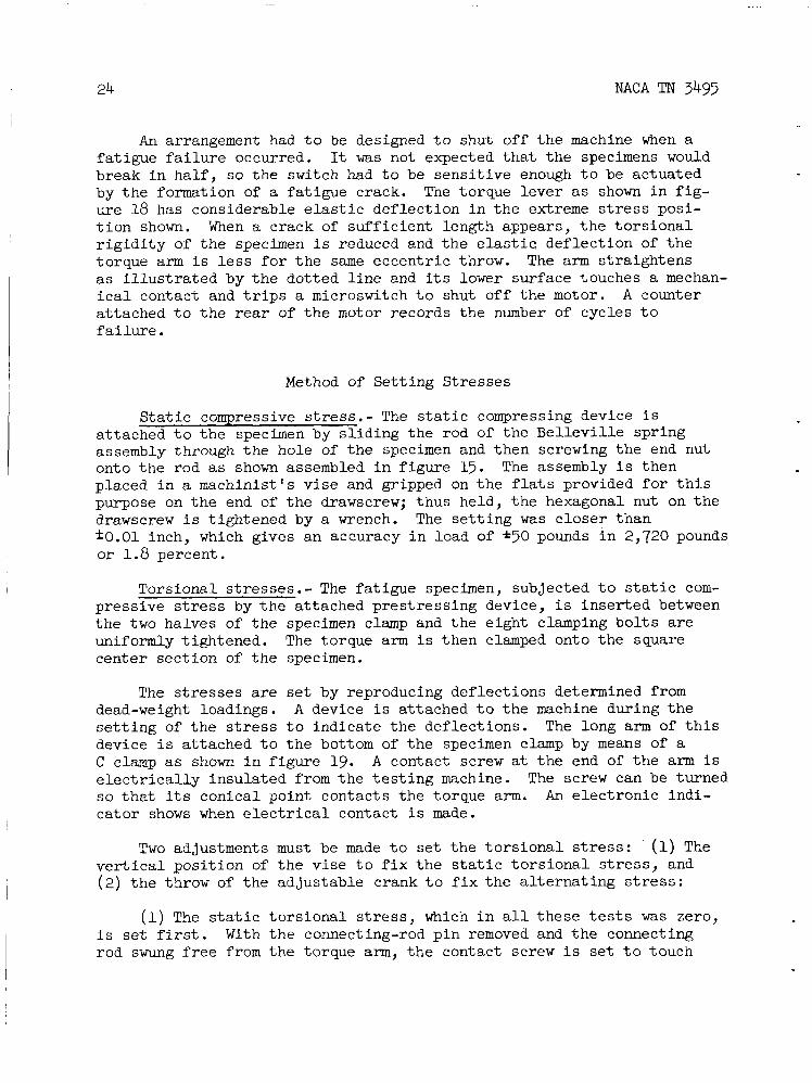
An arrangement had t o be designed t o shut off t h e machine when a fa t igue f a i l u r e occurred. It was not expected tha t t h e specimens would break i n h a l f , so t h e switch had t o be sens i t ive enough t o be actuated by t h e formation of a fa t igue crack. The torque lever as shown i n f i g - ure 18 has considerable e l a s t i c def lect ion i n t h e extreme s t r e s s posi- t i o n shown. When a crack of suf f ic ien t length appears, t h e t o r s i o n a l r i g i d i t y of t h e specimen i s reduced and t h e elastic, def lec t ion of t h e torque arm i s l e s s f o r t h e same eccentr ic throw. The arm straightens as i l l u s t r a t e d by t h e dotted l i n e and i t s lower surface touches a mechan- i c a l contact and t r i p s a microswitch t o shut off t h e motor. at tached t o t h e rear of t h e motor records t h e number of cycles t o f a i l u r e .
A counter
Method of Se t t ing Stresses
S t a t i c compressive stress.- The s t a t i c compressing device i s attached t o t h e specimen by s l i d i n g the rod of the B e l l e v i l l e spring assembly through t h e hole bf the specimen and then screwing t h e end nut onto the rod as shown assembled i n f igure 15. The assembly i s then placed i n a machinist 's v i s e and gripped on t h e f la t s provided fo r t h i s purpose on t h e end of t h e drawscrew; thus held, the hexagonal nut on t h e drawscrew i s t ightened by a wrench. The s e t t i n g w a s c loser than f O . O 1 inch, which gives an accuracy i n load of * 5 O pounds i n 2,720 pounds o r 1.8 percent.
Torsional stresses.- The fa t igue specimen, subjected t o s t a t i c com- pressive s t r e s s by t h e attached pres t ress ing device, i s inser ted between t h e two halves of t h e specimen clamp and t h e eight clamping b o l t s a r e uniformly t ightened. center sect ion of t h e specimen.
The torque arm i s then clamped onto the square
The stresses are set by reproducing def lect ions determined from dead-weight loadings. A device i s attached t o t h e machine during t h e s e t t i n g of t h e stress t o indicate t h e def lect ions. device i s attached t o t h e bottom of t h e specimen clamp by means of a C clamp as shown i n figure 19. e l e c t r i c a l l y insulated from t h e t e s t i n g machine. so t h a t i t s conical point contacts the torque arm. A n e lec t ronic indi- cator shows when e l e c t r i c a l contact i s made.
The long arm of t h i s
A contact screw at t h e end of t he arm i s The screw can be turned
Two adjustments must be made t o s e t the t o r s i o n a l stress: (1) The v e r t i c a l pos i t ion of t h e v i s e t o f i x t h e s t a t i c t o r s i o n a l s t r e s s , and (2) t h e throw of t h e adjustable crank t o f i x the a l t e r n a t i n g stress:
(1) The s t a t i c t o r s i o n a l s t r e s s , which i n a l l these t e s t s was zero, i s set f i rs t . With t h e connecting-rod p i n removed and t h e connecting rod swung f r e e from t h e torque arm, t h e contact screw i s s e t t o touch

4R NACA TN 3493 25
t h e torque arm. i f t h e s t a t i c t o r s i o n a l stress desired i s other than zero, a weight t o
With t h e crank set f o r zero throw, the connecting rod i s at tached t o t h e torque arm by inser t ing t h e connecting-rod pin. The height of t h e v ise i s then adjusted so t h a t contact i s j u s t made with t h e screw. The v ise locking screws are then t ightened t o hold t h e setting.
(2) The a l t e r n a t i n g stress i s set next.
This def lec t ion corresponds t o a zero s t a t i c stress;
- give t h a t stress i s hung from t h e torque arm a t t h e connecting-rod pin.
The connecting-rod p i n i s disconnected and swung aside and t h e weight pan i s at tached t o t h e torque arm at t h e connecting-Pod pin. Using t h e weight corresponding t o t h e maximum t o r s i o n a l stress of t h e fa t igue cycle, t h e contact screw i s set t o make contact. The weight pan i s removed and t h e connecting rod attached. determined from t h e appl icat ion of dead weight. crank i s t ightened t o hold t h i s adjustment.
The crank throw i s adjusted t o reproduce t h e d e f l e c t i o n as A locking screw on t h e
The stresses having been s e t , t h e indicator arm and screw are removed. After t h e cycle counter i s read, t h e machine i s turned on and t h e shutoff switch set . The switch i s set so t h a t contact is not qui te made between it and the torque arm but so t h a t a f e w pounds of force (e.g., t h e weight of a hand placed on t h e center of t h e torque arm) w i l l cause enough def lec t ion t o t r i p the switch.
T e s t Results
The r e s u l t s of t h e f a t i g u e tes ts are presented i n table 1, and i n f i g u r e 20 t h e amplitude of t h e a l t e r n a t i n g t o r s i o n a l stress i s p l o t t e d against the logarithm of t h e number of stress cycles t h a t caused f a i l u r e . Two p a r a l l e l s t ra ight l i n e s n ice ly f i t t h e two s e r i e s of f a t i g u e data. The curves are separated s u f f i c i e n t l y so tha t the s c a t t e r f o r t h e two curves does not overlap. A t 10 cycles, which i s a l i f e t i m e commonly used f o r comparison, the amplitude of t he t o r s i o n a l stress i s 13,000 p s i (probable e r r o r , f300 p s i ) and when the s t a t i c compressive stress of 21,700 p s i w a s superimposed on t h e t o r s i o n a l stress, i t s amplitude was increased t o 13,000 p s i (probable e r r o r , *?OO p s i ) .
7
The specimens d id not f a i l by complete rupture but by the formation of very narrow longi tudinal cracks i n t h e t es t sect ion. A crack of about 1/4 inch i n length w a s s u f f i c i e n t t o shut off t h e machine. w e r e so f i n e t h a t they could scarcely be seen with t h e naked eye. Some of t h e specimens cracked i n both tes t sect ions. The t e s t on specimen 2 was continued u n t i l t h e crack extended i n t o t h e f i l l e t a t t h e end of t h e t es t sect ion. I n t h e f i l l e t , t h e crack branched i n t o a circumferent ia l crack and a l s o continued longi tudinal ly . Black powder formed by a t t r i - t i o n of t h e surface of the crack marked t h e i n t e r s e c t i o n of t h e crack with t h e bore, thus revealing t h a t the cracks extended through t h e tes t sect ion.
The cracks

26 NACA TN 3495
Discussion of Test Results
It is i n t e r e s t i n g t h a t t h e fa t igue cracks formed along planes of maximum a l t e r n a t i o n of shear stress because t h e combined-alternating- s t r e s s data c i t e d earlier i n t h e report indicate tha t it i s t h e alter- nation of shear stress t h a t causes t h e failure. However, t h i s observa- t i o n of t h e d i rec t ion of propagation of t h e fa t igue crack can hardly be taken as an indicat ion of t h e f r a c t u r e mechanism, f o r other invest igators (refs. 33 and 34) have observed t h a t cracks caused by t o r s i o n a l s t r e s s e s of ten propagate normal t o t h e maximum normal stress. Perhaps it i s the or ien ta t ion of t he f l a w from which t h e crack i n i t i a t e s t h a t determines t h e d i rec t ion of t he propagation and t h e f l a w s might have acquired a preferred or ien ta t ion during t h e r o l l i n g process.
The formation of a longi tudinal crack w a s delayed by a longi tudinal compressive s t r e s s , although it has no component on t h e plane of t h e crack. Th i s lends support t o t h e c r i t e r i o n which s t a t e s t h a t it i s t h e sum of t h e orthogonal components of t h e normal s t a t i c stress t h a t i s e f fec t ive , because no d i rec t ion can be a t t r i b u t e d t o t h e ar i thmetic sum.
. The presence of microscopic res idua l stresses i n t h e specimen is
unl ikely because t h e t es t sec t ion of 0.50-inch outside diameter and 0.30-inch ins ide diameter was machined from t h e 1- by 4-inch stock. i s d i f f i c u l t t o imagine res idua l -s t ress gradients a t t h e center of t h e 1-inch thickness so s teep t h a t they would not be re l ieved by t h e machining.
It
The experimental r e s u l t s f o r t h e e f fec t of s t a t i c compressive s t r e s s are compared i n figure 21 with t h e curves f o r the e f f e c t of s t a t i c stress t h a t have been extrapolated i n t h e way predicted by t h e general s t r e s s c r i t e r i o n . It i s seen t h a t the data agree closely with the predicted behavior, although t h e t e s t s under compression were performed on a m e t a l d i f f e r e n t from t h a t t e s t e d under tension.
Most of the t e s t data examined have been l imited t o cases i n which t h e y ie ld s t rength was not exceeded. The behavior revealed by t h e t es t data may be very d i f f e r e n t from t h a t predicted by t h e general c r i t e r i o n i f yielding occurs, as can be seen by t h e sudden drop of permissible a l t e r n a t i o n of stress shown i n f i g u r e s 6 and 7(b), where t h e y i e l d s t rength was exceeded under other combinations of s t r e s s e s .
MODIFICATION OF OROWAN THEORY OF FATIGUE
TO INCLUDE EFFECT OF STATIC STRESS
The experimental information on t h e e f f e c t of s t a t i c s t r e s s e s on t h e permissible range of a l t e r n a t i n g stress i s generalized by t h e mathematical

NACA TN 3495 27
statement of t h e c r i t e r i o n . A val id theory of f a t i g u e should agree with t h i s general izat ion OY the known behavior. t a t i v e theory of fa t igue i n 1939, which w i l l be examined t o see whether the mechanism of f a i l u r e advanced i n it i s compatible with t h e c r i t e r i o n
Orowan proposed a semiquanti-
4 (ref. 3 5 ) .
Orowan's ana lys i s pred ic t s many aspects of t h e behavior of metals under repeated stress; he out l ines them as follows:
"(1) The quas i -br i t t l e nature of fatiwe frac ture . A metal, however duc t i le , can break i n a fa t igue t e s t without any appreciable ex terna l deformation, l i k e a b r i t t l e material. A f u r t h e r s i m i l a r i t y t o b r i t t l e f r a c t u r e i s t h a t f i n e cracks and other f a u l t s , which would not influence noticeably t h e s t a t i c s t rength of a d u c t i l e material, s u b s t a n t i a l l y impair i t s f a t i g u e endurance.
" ( 2 ) I n t e r n a l d i s t o r t i o n s . I n s p i t e of t h e possible absence of any ex terna l deformation, heavy l o c a l d i s t o r t i o n s can be observed microscopi- c a l l y on a material subjected t o a f a t i g u e t e s t . n a l d i s t o r t i o n s has been extended by t h e X-ray work of Gough and h i s col laborators , who found t h a t X-ray photographs of fa t igue-fractured metals show, i n t h e immediate neighbourhood of t h e f a t i g u e crack, quali- t a t i v e l y and quant i ta t ive ly t h e same a l t e r a t i o n s as those of metals f r a c - tured i n s t a t i c t e s t s .
The evidence f o r i n t e r -
"(3) Existence of safe ranges. The algebraic difference between t h e maximum and t h e minimum s t r e s s of t h e cycle i s ca l led t h e range of stress. For a f ixed mean stress of t h e cycle, t h e number of cycles t h a t t h e material can withstand increases rapidly with decreasing range of stress. For appl icat ions i n engineering it is of t h e highest importance t h a t , i n most cases, a l imi t ing range of stress e x i s t s below which t h e material w i l l withstand any number of cycles. By p l o t t i n g t h e r e s u l t s of fa t igue t e s t s as log S-log N curves a c h a r a c t e r i s t i c f ac t i s revealed: I n general, t h i s curve cons is t s of two s t r a i g h t p a r t s , one incl ined (representing t h e unsafe ranges) and one p r a c t i c a l l y hor izonta l ( repre- senting t h e behavior of t h e mater ia l a t t h e l imi t ing safe range). t r a n s i t i o n between t h e two s t r a i g h t p a r t s i s more or less rounded off."
The
However, t h e theory predic t s t h a t s t a t i c stress should have no e f f e c t on t h e permissible range of a l t e r n a t i n g s t r e s s . evidence, which indicates t h a t t h e e f f e c t of t h e s t a t i c stress i s very small or even negl igible , i s c i t e d i n t h e paper, t h e la rge c o l l e c t i o n of experimental evidence presented i n e a r l i e r sect ions of t h e present paper reveals an appreciable e f f e c t of the s t a t i c stress.
Although some experimental
Orowan's ana lys i s
%he e f f e c t of mean s t r e s s has a l ready been considered i n another theory of fa t igue presented by Shanley i n reference 36. evidence t o dis t inguish which of these two t h e o r i e s more c lose ly describes t h e phenomenon i s not ex is ten t .
Experimental

28 NACA TN 3495
w i l l be discussed b r i e f l y t o see whether it i s amenable t o a modifica- t i o n t h a t w i l l introduce t h e e f f e c t of t h e s t a t i c stress.
Orowan's theory is based upon the r e l a t i o n between t h e stress and t h e p l a s t i c s t r a i n e x i s t i n g a t microscopic inhomogeneities within t h e mater ia l . He c i t e s severa l experiments t ha t show t h a t local ized p l a s t i c s t r a i n does occur under repeated s t r e s s e s t h a t are beneath t h e y ie ld s t rength of t h e material. A stress t h a t would not cause yielding of the bulk of t h e material may cause the stress produced by a microscopic inhomogeneity t o reach t h e y ie ld s t rength and cause p l a s t i c flow, because of t h e stress concentration of t he homogeneity. The p l a s t i c flow l i m i t s t h e stress t o t h a t s t r e s s at which the flow occurs f o r t h e material i n t h a t region. A s t h e stress i s repeated, t h e p l a s t i c region work-hardens and the stress t o cause t h e yielding must increase. If the a b i l i t y t o flow i s exhausted and if t h e applied stress and the s t r e s s concentration of t h e inhomogeneity are great enough, t h e stress on t h e microscopic region w i l l exceed i t s rupture s t rength and a crack will form. After t h e p l a s t i c deformation stops, t h e local ized stress may not have exceeded t h e rupture s t rength and then the stress can be applied repeatedly with- out leading t o failure.
Orowan idea l izes t h e ac t ion of t h e microscopic p l a s t i c region embedded i n i t s e l a s t i c surroundings by t h e following model:
4
Sketch 2
The model cons is t s of a p l a s t i c element a i n s e r i e s with a . s p r i n g c , t h e assembly being i n p a r a l l e l with t h e springs b, which represent t h e elas- t i c surroundings.
From t h e two considerations (1) t h a t t h e t o t a l u n i t stress i s t h e sum of t h e forces on t h e p l a s t i c element and t h e p a r a l l e l e l a s t i c ele- ment and (2) t h a t t h e elongation of t h e s e r i e s element a together with c must equal t h a t of b, a l i n e a r equation between the p l a s t i c s t r a i n of t h e element E and t h e s t r e s s uc ac t ing upon it can be derived. This r e l a t i o n i s
P

NACA TN 3495 29
akl = uc + k E 2 P
I n which kl and -k2 are constants and u i s t h e appl ied s t r e s s . This func t iona l r e l a t i o n can be p lo t t ed i n t h e following manner:
Sketch 3
The work-hardening curve f o r t h e hypothet ical p l a s t i c element gives
€P: another r e l a t i o n between t h e stress uc and t h e p l a s t i c s t r a i n
I - € P
0 Sketch 4
These two r e l a t i o n s between t h e s t r a i n and stress f o r t h e p l a s t i c element must be s a t i s f i e d when a l t e r n a t i n g s t r e s s e s a r e appl ied t o t h e material. When a pe r iod ica l ly reversed, un iax ia l stress u i s applied t o a specimen, the s t r e s s and s t r a i n f o r t h e p l a s t i c element follow t h e work-hardening curve in t e r sec t ion w i t h l i n e BZ which represents t h e o ther r e l a t i o n between t h e stress and s t r a i n . Assuming t h a t s t r e s s i n g i n compression causes t h e same work-hardening as s t r e s s i n g i n tension, t he appl ica t ion of t he
OYF of sketch 5 , u n t i l ha l t ed at point p, t h e

30 NACA TN 3495
reversed s t r e s s causes t h e s t r e s s t o rise, and t h e s t r a i n t o reverse, over path PPI. (The ordinate represents t h e absolute value of t h e s t r e s s
t uc F
I I I I I I
A M \ 7.11
I C 0
I I I I I I .)
En \ B G c
Sketch 5
on t h e p l a s t i c element.) about a v e r t i c a l l i n e passing through P. On t h e next cycle, t h e t e n s i l e stress increases and t h e s t r a i n increases u n t i l P" i s reached; P'P" i s t h e segment of t h e strain-hardening curve t h a t had been r e f l e c t e d about t h e v e r t i c a l through P through P I . During subsequent cycles, t h e stress rises along a zigzag curve enclosed between t h e l i n e s of t h e t r i a n g l e ZB and ZC, which express t h e stress-strain r e l a t i o n , equation (1). hardening curve may be, t h e zigzag curve cannot r ise above t h e apex of t h e t r i a n g l e , point Z. OZ, then no f a i l u r e can occur no matter how many cycles of stress are applied. However, i f the amplitude of the applied a l t e r n a t i n g stress u i s great enough s o t h a t OZ exceeds t h e f r a c t u r e s t rength FG, then, a f t e r
Path PP' i s t h e strain-hardening curve re f lec ted
and i s now again r e f l e c t e d about t h e v e r t i c a l
Whatever t h e shape of t h e s t r a i n -
If t h e f r a c t u r e s t rength of t h e element i s grea te r than

NACA TN 3493
a c e r t a i n number of repe t i t ions , t h e s t r e s s w i l l exceed the f r a c t u r e s t rength and a fa t igue crack w i l l s tart (sketch 6 ) .
Sketch 6 Without the i n s e r t i o n of any addi t iona l information on the var ia t ion
of any of' t h e parameters with s t a t i c stress, t h e theory i s shown by Orowan t o predict t h a t s t a t i c s t r e s s e s should have no e f f e c t on t h e permissible range of stress below the e l a s t i c l i m i t . The t e s t s quoted i n an earlier sec t ion of t h e paper, and p a r t i c u l a r l y those of Ros' and Eichinger ( r e f . 3 ) and S m i t h (ref. 14), show t h a t t h i s i s t h e case when t h e s t a t i c stress i s shear but t h a t s ta t ic normal stresses have no appreciable e f f e c t .
Orowan's statement tha t the l imi t ing safe range depends only on the s t rength of the p l a s t i c region and on t h e "stress concentration" f a c t o r should be emphasized. More spec i f ica l ly , t h e mechanism of f a t i g u e out- l i n e d by Orowan states t h a t the safe range i s determined by the s t rength a t t a i n e d by t h e , p l a s t i c region i n the most severely work hardened condi- t i o n t h a t can be obtained by t h e ac t ion of a l t e r n a t i n g s t r a i n s t o a region confined by the e l a s t i c surroundings and the nature of t he inhomo- geneity. The question now arises as t o what gross s t a t i c measurement i s most c lose ly associated w i t h t h i s s t rength property of the p l a s t i c ele- ment of t h e model.
The ult imate s t rength, which i s the maximum s t a t i c load divided by the o r i g i n a l undeformed cross-sect ional area, seems t o have l i t t l e con- nection with the mechanism because there may be considerable reduction i n cross-sectional a rea before f r a c t u r e occurs. The " t rue strength," which i s defined as load a t f r a c t u r e divided by t h e a c t u a l f ractured

NACA TN 3495 32
area, has more significance; however, t h e s i t u a t i o n i s complicated by the complex stress condition present across t h e necked sect ion. Bridgman (ref. 37) removes t h e complication by introducing the concept of "final flow stress," which he defines as t h e longi tudinal normal stress on t h e outer surface of t h e neck at t h e t i m e of rupture. mathematical considerations, he obtains t h e s t r e s s - s t r a i n conditions present i n t h e neck t h a t are needed t o calculate the flow stress.
From experimental and
The f inal-f low-stress descr ipt ion of t h e s t rength property of a mater ia l has more significance than t h e others because, i n it, considera- t i o n has been taken of t h e a c t u a l stresses present a t the failure region i n the s t a t i c t es t . However, it s t i l l i s not exact ly t h e "s t rength of t h e p l a s t i c region" mentioned i n Orowan's analysis because i t s work- hardened state was obtained by a s ingle appl icat ion of a unid i rec t iona l load and it underwent necking, while t h e p l a s t i c region was subjected t o a l t e r n a t i n g s t r a i n s and was confined. A corre la t ion between the two propert ies seems l i k e l y .
h e n i f the f i n a l flow s t r e s s ms t h e rupture s t rength of t h e p l a s t i c region, computation of t h e fa t igue s t rength from t h e f i n a l f l o w s t r e s s f o r various materials would not be possible because t h e nature of the inhomo- genei ty e f f e c t i v e i n the f a t i g u e f a i l u r e i s not known. However, f a c t o r s t h a t cause a v a r i a t i o n i n t h e flow stress without a f f e c t i n g t h e s t ruc ture of t h e material should a l s o cause a comparable change i n t h e l imi t ing safe f a t i g u e s t rength.
The ul t imate s t rength, t r u e rupture s t rength, and t h e f i n a l flow stress are a l l influenced by hydrostat ic pressure i n a manner similar t o t h a t i n which s t a t i c normal stresses affect fa t igue failure. I n t a b l e 2 some t y p i c a l t es t r e s u l t s f o r t h e e f f e c t of hydrostat ic pressure on t h e t r u e s t rength and t h e f i n a l flow stress are presented. The values ca l led t h e "pressure coeff ic ients"5 given i n t h e t a b l e are t h e r a t i o s of t h e change i n t r u e s t r e s s corresponding t o a change i n hydrostat ic pressure and of t h e change i n f i n a l flow stress corresponding t o t h e change i n hydrostat ic pressure. These were obtained by p l o t t i n g t h e data , f i t t i n g a s t r a i g h t l i n e t o t h e points , and measuring t h e slope. The data have considerable s c a t t e r , but a d e f i n i t e funct ional r e l a t i o n with t h e hydro- s t a t i c pressure i s evident.
The changes i n f i n a l flow stress corresponding t o t h e changes i n hydrostat ic pressure f o r t h e s t e e l s presented i n t a b l e 2 are 0.90, 0.90, 0.60, and 0.80, which average 0.80 f 0.08. The changes i n permissible s t r e s s amplitude corresponding t o the applied uniax ia l mean stress a r e 0.22, 0.24, and 0.25 f o r Nishihara 's s t e e l s (see f i g . 5 ) , averaging 0.237 iO.009; 0.23 f o r Roz's low-carbon s t e e l s ; and 0.20 f o r Newmark's t e s t s on 2024-T (24s-T) aluminum. These numbers a r e values f o r a, t h e
5Note t h a t t h i s "pressure coeff ic ient" i s d i f fe ren t from t h a t com- monly used i n t he f i e l d of high-pressure physics.

NACA TN 3493 33
coefficient: of t h e sum of t h e orthogonal s t a t i c stress components, which appears i n t h e proposed stress c r i t e r i o n f o r fa t igue . If t h e s t a t i c s t r e s s i s expressed, i n terms of the hydrostat ic pressure, t h e new coef f i - c ien t i s 3 x a, thus making t h e average value f o r t h e hydrostat ic pressure coeff ic ient coeff ic ient f o r f a t i g u e i s close t o t h e value of 0.80 f o r t h e pressure coef f ic ien t f o r t h e f i n a l flow stress f o r a similar material. This may indicate t h a t t h e f i n a l flow stress ( the ref ined rupture s t rength defined by Bridgman) has a close r e l a t i o n t o t h e "strength of t h e p l a s t i c region" appearing i n Orowan's analysis .
3 x 0.237 = 0.71 *0.03. The value of 0.71 f o r t h e p r e s s w e
Although t h e comparison was made using hydrostat ic stress, it i s not intended t o l i m i t t h e e f f e c t t o t h e ac t ion of t h e hydrostat ic (equi- t r i a x i a l ) stress s t a t e . The flow on t h e plane on which s l i p occurs i s affected by t h e normal stress on t h a t plane and the normal stress can r e s u l t from t h e appl icat ion of e i t h e r uniaxial , b i a x i a l , or t r i a x i a l s t a t i c stresses. Bridgman suggested (pr iva te correspondence) t h a t t h i s can be shown by t h e data i n chapter 15 of h i s book ( r e f . 37). Here t h e e f f e c t of a uniax ia l compressive stress on maximum t o r s i o n a l s t rength i s presented. The uniax ia l pressure coef f ic ien t , t h e change i n maximum shear s t rength corresponding t o t h e change i n compressive stress, i s Q.21. mum shear stress.) the uniax ia l pressure coef f ic ien ts f o r fa t igue of 0.22, 0.24, 0.25, and 0.20 mentioned above. Pressure coef f ic ien ts cannot be obtained from t h e other tests on t h e e f f e c t of a uniaxial compressive stress on t o r s i o n presented i n Bridgman's book because of t h e uncertainty i n t h e diameter of t h e t es t sec t ion caused by t h e yielding.
(The f i n a l flow s t r e s s i n t h e t o r s i o n a l t es t i s equal t o t h e maxi- This coef f ic ien t 0.21 can be compared d i r e c t l y with
The above considerations make it reasonable t o i n s e r t t h e dependence of t h e s t rength of t he p l a s t i c region upon t h e s t a t i c normal stress i n t o t h e Orowan theory. When s t a t i c compressive s t r e s s e s a r e applied during p l a s t i c deformation, t h e f r a c t u r e s t rength of t h e p l a s t i c element repre- sented by GF i n sketch 6 i s increased, thereby r a i s i n g t h e f a t i g u e s t rength. It is inferred t h a t deformation under t e n s i l e stress reduces GF and thereby t h e fa t igue s t rength. With t h i s modification, t h e theory predic t s the experimentally revealed e f f e c t t h a t s t a t i c stress has upon t h e permissible amplitude of a l t e r n a t i n g stress.
University of California, Los Angeles, Calif., March 24, 1954.

34 NACA TN 3495
APPENDIX A
ANALYSIS OF STRESSES AT CRACKS OF VARIOUS ORIENTATIONS
An examination will be made of cracks or iented at d i f f e ren t angles under seve ra l combinations of s t r e s s t o f ind the maximum local ized stresses t h a t occur i n each case. The shape of t h e crack i s assumed t o be a much elongated e l l i p t i c a l hole, because the stresses about t h i s shape have been solved by Neuber and are presented i n a graphical form i n h i s book (ref. 38) and because t h i s shape i s a reasonable idea l iza- t i o n of a flakelike hole . He has solved the case i n which the volume containing t h e hole i s subjected t o pure shear (1) and a l s o the case f o r tens ion ( 2 ) . of t h e hole . )
(The dimensions of t h e volume are la rge compared with those
Lc
7
(1) Sketch 7 The general s t r e s s state applied t o t h e body containing t h e hole
can be expressed by shear and normal stresses, which a c t on planes enclosing t h e hole and a r e or iented p a r a l l e l and perpendicular t o i t s axes : t
- I \ \ \ \ I - + A t t h e hole, t he loca l ized stresses caused by the shear component
can be superimposed on those a r i s i n g from t h e normal component; t h i s superposit ion i s permissible by t h e theory of e l a s t i c i t y because t h e deformations are small.
The shear and normal components S s and N which a c t on t h e enclosing planes i n the above sketch were found graphical ly by use of t h e Mohr c i r c l e (ref. 2 3 ) f o r severa l d i f f e ren t or ien ta t ions and stress states. The normal stress p a r a l l e l t o t h e major a x i s of t h e hole was not found

NACA TN 3495 35
because it makes no appreciable contr ibut ion t o t h e stress at t h e end of t h e hole.
Figure 22(a) shows t h e value of t h e normal stress at t h e surface of t h e hole, p a r a l l e l t o i t s surface, which r e s u l t s from a t e n s i l e stress applied t o t h e element. Note t h a t t h e surface stress reaches a maximum a t t h e end of t h e hole on the x-axis. The normal stress on t h e x-axis i s shown on t h e r i g h t as a funct ion of t h e dis tance away f r o m t h e edge of t h e hole.
The s t r e s s e s caused by pure shear applied t o t h e element are shown i n figure 22(b) . maximum a t a point on it t h a t i s 45' t o the axes. t h e maximum shear t h a t a c t s on t h e x-axis. However, t h i s i s not t h e grea tes t shear stress; it occurs a t t h e same point on the surface where t h e normal stress i s grea tes t .
The normal stress p a r a l l e l t o t h e surface reaches a On t h e r i g h t is shown
The l o c a l stress, which r e s u l t s from t h e superposit ion of the l o c a l stresses caused by t h e applied shear and normal stress components, i s great a t two points . One point i s on t h e x-axis, a short dis tance beneath t h e surface, where t h e maximum shear s t r e s s caused by t h e applied shear stress component adds t o t h e local ized normal s t r e s s caused by t h e applied normal stress component. The other highly s t r e s s e d point i s at t h e surface of t h e hole, near t h e end of t h e hole, where t h e sum of t h e local ized normal stresses caused by t h e applied shear and applied normal stress components reaches a maximum. The l o c a l combined shear and nor- m a l stresses f o r the f irst point were calculated by means of t h e Mohr c i r c l e and t h e combination was found t o be less than t h a t f o r t h e other point , which i s on t h e surface.
The maximum stresses were found by t h e following method and are presented i n t a b l e 3 . The e f f e c t of stress state A, i d e n t i f i e d i n t h e table, on t h e crack or iented i n pos i t ion 2 w i l l be determined as an example.
The s t r e s s e s caused by u1 on planes enclosing t h e hole, p a r a l l e l The and normal t o i t s axes, were found by means of the Mohr c i r c l e .
normal s t r e s s N, which i s given i n t h e second column, i s equal t o 0.85ul, and t h e shear stress t o 0.35al. f i g u r e 22(a) and those caused by t h e normal component given i n figure 22(b) were mult ipl ied by these f rac t ions , 0.85 and 0.35, respect ively, and then added graphical ly t o f i n d the maximum l o c a l stress a t t h e notch. maximum stress f o r t h i s case wits found t o be on a plane whose normal makes about a 20° angle with t h e x-axis, and t h i s maximum sum was llal. The shear stress at t h e surface i s equal t o one-half t h e normal stress, t h a t i s , 5 . 5 O l .
Ss, which i s i n t h e t h i r d column, i s equal The l o c a l stresses caused by the shear components given i n
The

36 NACA TN 3495
This process was repeated f o r t h e f i v e crack or ientat ions and t h e I n a l l cases, except f o r or ientat ions 2 and 4 w i t h t h r e e stress s t a t e s .
stress state C, t h e grea tes t value of s t r e s s w a s the same (1101 f o r t h e normal and 5 . 5 ~ ~ f o r t h e shear). t ransverse and longi tudinal stress were equal i n magnitude, t h e maximum s t r e s s e s were s l i g h t l y higher (normal s t r e s s equal t o 13al and t h e shear s t r e s s equal t o 6.501).
For t h e one exception, i n which t h e
Thus, it i s seen t h a t t he maximum of t h e local ized s t r e s s e s a t t h e elongated holes i s determined by t h e grea te r i n magnitude of t h e applied pr inc ipa l stresses and i s but s l i g h t l y influenced by the secondary s t r e s s .

NACA T N 3495 37
APPENDIX B
TRANSFORMATION OF GENERAL CRITERION INTO TERMS OF
MAXIMUM AND MINIMUM STRESS RATIO
The transformation of t h e general c r i t e r i o n i n t o terms of maximum and minimum stress r a t i o i s as follows:
Sketch 9
‘stati
Commonly, t h e stress cycle i s described by R:
‘min ‘maX
R E -
The ha l f range u i s given by
= ‘nax ‘min 2
and t h e mean stress S is
‘max + urnin S = 2
1 + R 0- - 2 -- 1 - R 2

38
Define
1 + R m=- 1 - R
NACA TN 3495
The normal form of t h e general c r i t e r i o n i s as follows, where u ' s a r e t h e amplitudes of t he a l t e r n a t i n g pr inc ipa l normal s t resses :
2 -/(ul 1 3
- u2)2 + (u2 - u5)2 + (01 - 03) = A - a(s, + % + sz)
A t t h e surface u3 = 0 so t h a t
Now
where
- = A - a(S, + S y + Sz) 3 1 1 2
S = mu
1 + R m E - 1 - R
and
2 2 L i2u 3 1 - 20 1 2 u + 2a2 = A - m(u1 + u2)
2 u 1 - u 1 2 u + u 2 = q 4 2 - m(O1 + 02)]
= [. - bm(ul + u 2 g 2
where
3 a = - A E

.
NACA T N 3493
Reduced t o standard form f o r conic sections,
Au12 + Bula2 + CuZ2 + Dal + Ea2 + F = 0
where
A = C = 1
2 a F = 2 2
39
For the s t r e s s cycle where u = S,, u2 = Sy, and u3 = S,, m i s
uni ty . 1

40
REFERENCES
NACA TN 3493
1. Gough, H. J . : Some Experiments on t h e Resistance of Metals t o Fatigue Under Combined St resses . R . & M. No. 2522, B r i t i s h A.R.C., 19%.
2. Findley, W. N.: Fatigue of 7 6 ~ ~ 6 1 Aluminum Alloy Under Combined Bending and Torsion. Proc. A.S.T.M., vol . 52, 1952, pp. 818-833.
3. Puchner, 0.: Zur Dauerhaltbarkeit von Formelementen der Welle b e i ueberlagerter wechselnder Beige- und Verdrehbeanspruchung. Archiv angewandte Wiss. und Technik, Bd. 14, N r . 8, Aug. 198,
Schweizer
pp. 217-229.
4. Sawert, Walter: Verhalten der Baustghle b e i wechselnder mehrachsiger Beanspruchung. Z.V.D.I . , Bd. 87, N r . 39/40, Oct. 2, 1943, pp. 609-615.
D i e Bruchgefahr f e s t e r K6rper b e i wiederhalten Beanspruchung-Ermcdung. Metalle. Bericht 173, Eidgenos s i s che M a t erialprufungs- und Versuchsans t a l t fGr Indus t r i e, Bauwesen und Gewerbe (Zurich), Sept. 1950.
5. Roz, M., and Eichinger, A.: I
6. Maier, A . F.: Wechselbeanspruchung von Rohren unter Innendruck. S t ah l und Eisen, Bd. 54, Heft 50, Dec. 13, 1934, pp. 1289-1291.
7. Sachs, G.: Zur Ableitung e iner Fliessbedingung. Z.V.D.I . , Bd. 72, N r . 22, June 2, 1928, pp. 734-736.
8. Hencky, Heinrich: Zur Theorie p l a s t i s che r Deformationen und der hierdurch i m Mater ia l hervorgerufenen Nachspannungen. Bd. 4, Heft 4, Aug. 1924, pp. 323-334.
Z.a.M.M.,
9. B a t t e l l e Memorial I n s t i t u t e : Prevention of t h e Fa i lure of Metals Under Repeated S t r e s s . John Wiley b Sons, Inc. , 1941, pp. 115-117.
10. Turner, I,. B.: The Strength of S tee l s i n Compound S t r e s s and Endurance Under Repet i t ion of S t ress . Engineering, vo l . X C I I , Aug. 25, 1911, pp. 247-250.
11. Sisco, Frank T.: Modern Metallurgy f o r Engineers. Second ed., Pitman Pub. Corp. (New York) , 1948.
12. Thum, A. , and Petersen, C . : The Fatigue Strength of Cast Iron. Archiv Eisenhiittenwesen, Bd. 16, Heft 8, Feb. 1943, pp. 309-312.
13. Nishihara, Toshio, and Sakurai, Tadakazu: Fatigue Strength of S t e e l for Repeated Tension and Compression. Trans. SOC. Mech. Eng. (Japan), vol . 5, no. 18, Feb. 1939, pp. 1-27 - 1-29. English summary, pp. S-8 - S-9.)
(Text in Japanese.
6R NACA TN 3495 41
14. Smith, James 0.: The Effect of Range of S t r e s s on t h e Fatigue Strength of Metals. Ill., vol. 39, no. 26, Feb. 17, 1942.
Bul l . No. 334, Eng. Exp. S ta t ion , Univ. of
15. Newmark, N. M., Mosberg, R. J., Munse, W. H., and El l ing , R . E.: Fatigue Tests i n Axial Compression. Proc. A.S.T.M., vol. 51, 1951, pp. 792-803; discussion, pp. 803-810.
16. Ludwik, P. , and Krystof, J.: Einf luss der Vorspannung auf d i e Dauerfestigkeit . Z . V . D . I . , Bd. 77, N r . 24, June 17, 1933, PP. 629-635.
17. Moore, H. F., and Lewis , R. E.: Fatigue Tests i n Shear of Three Non-Ferrous Metals. Proc. A.S.T.M., vol . 31, p t . 2, 1931, pp. 236-242.
18. Gough, H. J., and Pol lard, H. V.: bined Alternat ing S t resses . Proc. I n s t i t u t i o n Mech. Eng. (London), vol . 131, Nov. 1935, pp. 1-103.
The Strength of Metals Under Com-
19. Lea, F. C. , and Budgen, H. P.: Combined Torsional and Repeated Bending St resses . pp. 242-245.
Engineering, vol . C X X I I , Aug. 20, 1926,
20. Ono, Akimasu: Fatigue of S tee l s Under Combined Bending and Torsion. Memoirs, College of Eng., Kyushu Imperial Univ., vo l . 11, no. 2, 1921, pp. 117-142.
21. Nimhanminne, S. K.: The Fa i lure of Material Under Constant Torsion and Alternat ing Bending. Master's Thesis, Bat tersea Polytechnic Ins t . , 1931.
22. Huit t , W. J.: The Fai lure of Nickel Alloy S t e e l Under Torsion by t h e Addition of Alternat ing Bending. Master's Thesis, Bat tersea Polytechnic Ins t . , May 1935.
23. Timoshenko, S.: Theory of E l a s t i c i t y . McGraw-Hill Book Co., Inc. , 1934, P. 187.
24. H i l l , R . : The Mathematical Theory of P l a s t i c i t y . The Clarendon Press (Oxford), 1950, p. 17.
25. Marin, Joseph, and Shelson, W i l l i a m : B iax ia l Fatigue Strength of 24s-T Aluminum Alloy. NACA TN 1889, 1949.
26. Morikawa, G. K., and Griff is , L.: The Biaxia l Fatigue Strength of Low-Carbon Stee ls . pp. 167-s - 174-s.
The Welding Jour . , vo l . 24, Mar. 1945,

42 NACA TN 3495
27. Bailey, R. W.: Ductile Materials Under Variable Shear S t ress . Engineering, vol . C I V , Ju ly 27, 1917, pp. 81-83.
28. Stanton, T . E., and Batson, R . G. : On the Fatigue Resistance of Mild S t e e l Under Various Conditions of S t ress Distr ibut ion. Engineering, vol. C I I , Sept. 15, 1916, pp. 269-270.
29. Sines, George: Fa i lure of Materials Under Combined Repeated S t resses With Superimposed S t a t i c Stresses . Ph. D. Thesis, Univ. of Calif., Los Angeles, Aug. lB3.
30. Marin, J.: Engineering Materials. Prentice-Hall, Inc. , 1952.
31. Anon.: Alcoa Aluminum and I ts Alloys. Aluminum Co. of Am. (P i t t sburgh) , 1950.
32. Anon.: Handbook of Mechanical Spring Design. Associated Spring Corp. ( B r i s t o l Corn.), 1951.
33. Southwell, R . V. , and Gough, H. J.: On t h e Concentration of S t r e s s i n t h e Neighbourhood of a Small Spherical Flaw; and on t h e Propagation of Fatigue Fractures i n " S t a t i s t i c a l l y Isotropic" Materials. London, Dublin, and Edinburgh Ph i l . Mag. and Jour . Sci . , ser. 7, vo l . 1, no. 1, Jan. 1926, pp. 71-97; a l s o R. €i M. No. 1003, B r i t i s h A.R.C., 1926.
34. Smith, James 0.: The Effect of Range of S t r e s s on t h e Torsional Fatigue Strength of S tee l . Univ. of Ill., vol . 33, 1939.
Bull . No. 316, Eng. Exp. Stat ion,
35. Orowan, E.: Theory of t h e Fatigue of Metals. Proc. Roy. SOC. (London), ser. A, vol. 171, no. 944, May 1, 1939, pp. 79-1-06.
36. Shanley, F. R . : A Theory of Fatigue Based on Unbonding During Reversed S l ip . P-350, The Rand Corp., Nov. 11, 1952; Supplement, May 1, 1953.
37. Bridgman, P. W.: Studies i n Large P l a s t i c Flow and Fracture With F i r s t Special Emphasis on t h e Effec ts of Hydrostatic Pressure.
ed., McGraw-Hill Book Co., Inc. , 1952, Ch. 1.
38. Neuber, H.: Theory of Notch Stresses: Pr inc ip les f o r Exact S t r e s s Calculation. J . W. Edwards (Ann Arbor, Mich.), 1946.
39. Nishihara, Toshio, and Kojima, Kohei: Diagram of Endurance L i m i t of Duralumin f o r Repeated Tension and Compression. Trans. SOC. Mech. Eng. (Japan), vol . 5 , no. 20, Aug. 1939, pp. 1-1 - 1-2. Japanese. English summary, p. s-67.)
(Tex t i n

NACA TN 3493 43
40. Hankins, G. A.: Torsional Fatigue Tests on Spring Steels. Special Rep. No. 9, Ehg. Res., Dept. Sci. and Ind. Res. ( G r . Brit.), 1929.
41. Pomp, A., and Hempel, M.: Das Verhalten von Gusseisen unter Zug- Druck-Wechselbeanspruchung. Stahl und Eisen, Bd. 37, Heft 40, OCt. 1937, pp. 1125-1127.
42. Johnson, J. B. : Fatigue Characteristics of Helical Springs. The Iron Age, vol. 133, no. 11, Mar. 15, 1934; no. 12, Mar. 22, 1934, pp. 24-26.
43. Moore, H. F., and Jasper, T. M.: An Investigation of the Fatigue of Metals. Bull. No. 142, Eng. Exp. Station, Univ. of Ill., vol. 21, no. 37, May 26, 1924, p. 60.
44. McAdam, D. J., Jr.: The Endurance Range of Steel. Proc. A.S.T.M., V O ~ . 24, pt. 2, 1924, pp. 574-600.
45. Hohenemser, K., and Prager, W.: Under Complex Stresses. June 2b, 1933, pp. 342-343.
The Problem of Fatigue Strength Metallwirtschaft, Ed. XII, Heft 24,

44
Spec imen
1
2
3
4
5
6
7
8
9
10
11
12
13
TABLE 1
TEST RESUETS
[Inside dim., 0.298 in.] L
Outside d i m . ,
in.
0.4974
4983
.4980
4983
-4967
.4961
.4954
4975
.4964
De st royed
4975
.4@6
.4965
Weight at 20-in. lever arm,
lb
17
15
19
19 (compressed)
17 (compressed)
15 (compressed)
16 (compressed)
14
18 (compressed)
----------------
1% (compressed)
16
1%
NACA TN 3495
Cycles to failure
2,082,000
4,354,000
390, 000
1,066,000
4,241 , 0 00
15 , 436,000
7,038 , 000
14,552,000
2,103,000
----------
8,756,000
2,190,000
4,813,000

NACA TN 3495
Applied pressure, psi: Atmospheric . . . . . . . . 169 40 x 103 . . . . . . . . . 219 140 . . . . . . . . . 385
Pressure coefficient . . . . 1.60
. ~~
45
146 164 284
0.90
TABLE 2
Applied pressure, psi: . . . . . . . . Atmospheric 174 58 x 103 . . . . . . . . . 213 201 422
Pressure coefficient . . . . 1.30
EFFECT OF HYDROSTATIC PRESSURE ON TRUE RUPTURE STRENGTH
150 170 314 0.80
LData from ref. 371
True strength Final flow stress
Applied pressure, psi: Atmospheric . . . . . . . . 54 x 103 . . . . . . . . .
117 . . . . . . . . . 188 . . . . . . . . .
Pressure coefficient . . . .
191 250 314 470 1.50
169 204 236 340 0.90
2-1 steel,b normalized at 1,650~ F for 1/2 hr I I
Applied pressure, psi: Atmospheric . . . . . . . . 53 x 103 . . . . . . . . . 87 . . . . . . . . . 168 . . . . . . . . .
Pressure coefficient . . . .
166 204 247 221 0.60
Composition:
bComposition:
0.34 carbon, 0.75 molybdenum, 0.017 phosphorus,
0.45 carbon, 0.83 molybdenum, 0.016 phosphorus,
a
0.033 sulfur, and 0.18 silicon.
0.035 sulfur, and 0.19 silicon.
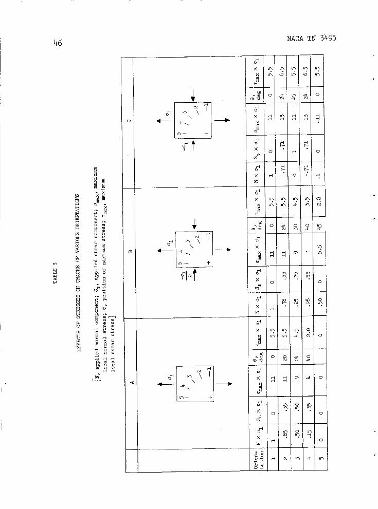
46 NACA TN 3495
d 0
t-
d b
f-
N d
* \ ' \
In- t
+

NACA TN 3495
I
Z W
I- cn 3
g 1.0
(r: .8
w .6
.4 (3
0 .2
m o
z z W
47
MAX. SHEAR STRESS OCTAHEDRAL SHEAR STRESS TOTAL STRAIN ENERGY -
MAX. PRINCIPAL - -
- -
- -
- -
I l l l l l l l l -
STRESS CRITERIA (3
Z W
z n
m z 0 U LL
cn cn W U I- cn U W I cn
a
(3 z Z W
a m z 0 a LL
cn u7 W U I- cn U W I cn
a
I I-
Z W a I- cn W 3 (3
l- L L
z W
cu \
( 3 1
- a 0
m
-
~~
MAX. SHEAR STRESS OCTAHEDRAL SHEAR STRESS TOTAL STRAIN ENERGY
-
- .4
.2
-
-
TORSIONAL SHEAR STRESS 1/2 BEND. FATIGUE STRENGTH
( a ) Chrome-vanadium s t e e l .
STRESS CRITERIA
( b ) "Si la l" cas t i ron.
Figure 1.- In terac t ion of bending and tors ion i n fa t igue . (Data from r e f . 1.)

48 NACA TN 3495
f I
I .2
I .o .8
I Y n n I t
I
b A A
i I
STRESS CRITERIA PRINCIPAL
.8 STRESS - I
i STRESS CRITERIA
*6 A t 4t-K PRINCIPAL
Y I I 8 L . W W
1 MAX. SHEAR STRESS
SHEAR STRESS . OCTAH E D R A L
1 1 I ALT. TRANSVERSE (PRINCIPAL) STRESS
n ~ x i m FATlGlJ ' STRENGTH 12 p .-.In*--
-.4 t I / /
- 1.2 L: fl f I v
Figure 2.- Comparison of Sawert's data (ref. 4) with failure criteria. Annealed mild steel; fatigue strength at 107 cycles of reversed stress.

'R NACA TN 3495 49
I I- (3 z W K I- Cn c
I .2
I .o .8
.6
4
.2 0 -
a d
m
-.2
w * -4
-.6
-.8
- 1.0
-1.2
STRESS CRITERIA
PRINCIPAL STRESS
MAX. SHEAR STRESS
SHEAR STRESS
-
-
- OCTAHEDRAL
ALT. PRINCIPAL STRESS, p, -
BEND. FAT. STRt
A I
-t
NGTH I +4-*rJ4-k+
PURE BENDING
A I
J n
1 I
U V
! 0 'ISILAL" CAST IRON 4 + Cr-Va STEEL
Figure 3.- Comparison of Gough's combined bending and torsion data Fatigue strength at 107 cycles (ref. 1) with failure criteria.
of reversed stress.

NACA TN 3495
>- o 7 W 3 0 W K L L
w K 3 J
LL a
K
W I cn
a
J
X a
O F 8
K
W I cn J
K D W 1 I- o 0
a
a
a
>- (3 K w z W
7
K I- cn -J
0 I-
- a
6
4
2
0 1.0 1.2 1.4 I .6 1.8 2.0 v 1.0 1.2 1.4 I .6 1.8 2.0
MAXIMUM SHEAR IN TORSION TEST .. .
MAXIMUM SHEAR N BEND TEST Figure 4.- Compazison of t o r s ion and bending fa t igue t e s t s w i t h f a i l u r e
c r i t e r i a . (Data from r e f . 1. )

NACA TN 3495
.- v) a 0000000 0000000
In b-b-cu 00 b eLoInLommd-
O-OnO 0 oao-on
.- v) a
i 3 a h
Y
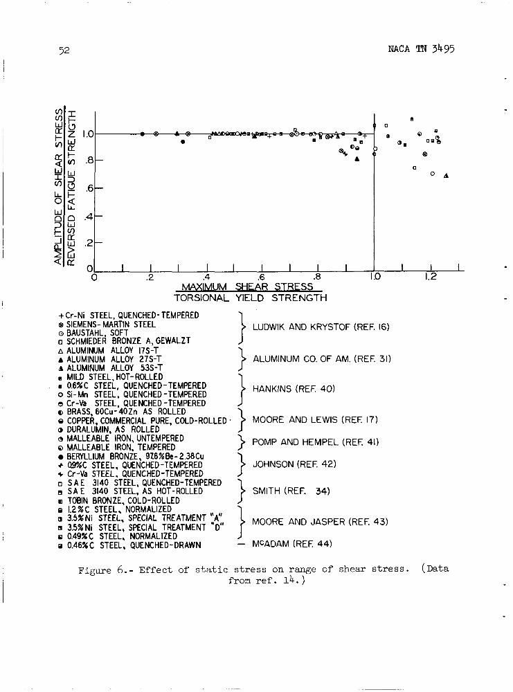
52 NACA !FN 3495
I .o
.8
.6
.4
.2
0 0 .2 .4 .6 .8 I .o 1.2
IMUM SHEAR STRESS TORSIONAL YIELD STRENGTH
+ Cr-Ni STEEL, QUENCHED- TEMPERED
a BAUSTAHL, SOFT o SCHMIEDER BRONZE A, GEWALZT A ALUMINUM ALLOY 17s-T A ALUMINUM ALLOY 27s-T A ALUMINUM ALLOY 53s-T a MILD STEEL, HOT-ROLLED
0.6% C STEEL, QUENCHED - TEMPERED o Si-Mn STEEL, QUENCHED -TEMPERED e Cr-Va STEEL, QUENCHED -TEMPERED o BRASS, 60Cu-40Zn AS ROLLED o COPPER, COMMERCIAL PURE, COLD-ROLLED @ DURALUMIN, AS ROLLED o MALLEABLE IRON, UNTEMPERED Q MALLEABLE IRON, TEMPERED
+ 09%C STEEL, QUENCHED-TEMPERED + Cr-Va STEEL, QUENCHED-TEMPERED o S A E 3140 STEEL, QUENCHED-TEMPERED 0 S A E 3140 STEEL, AS HOT-ROLLED m TOBIN BRONZE. COLD-ROLLED E 1.2XC STEEL, NORMALIZED m 3.5%Ni STEEL, SPECIAL TREATMENT "A" E 35XNi STEEL, SPECIAL TREATMENT "D" o 0.49%C STEEL, NORMALIZED o 0.46XC STEEL, QUENCHED-DRAWN
SIEMENS- MARTIN STEEL
BERYLLIUM BRONZE, 976XBe-2.3BCu
LUDWIK AND KRYSTOF (REF. 16)
ALUMINUM CO. OF AM. (REF. 31)
HANKINS (REF 40) 1 } MOORE AND LEWIS (REF: 17) . ) POMP AND HEMPEL (REF; 41)
} JOHNSON (REF. 42)
SMITH (REF. 34)
MOORE AND JASPER (REF. 43) i - MCADAM (REF. 44)
Figure 6.- Effect of s t a t i c s t r e s s on range of shear s t r e s s . (Data from r e f . 14. )

NACA TN 3495
0 b 0 X - L 1.0 I +
I
.
O X
m m W U I- tn
z W
0'
rn t; .75
b MATERIAL FATIGUE EST. SHEAR
+0.078 C STEEL 34,000 psi 24,000 psi .25 - x .251 C STEEL 37,000 psi 54,000 psi
.304 C STEEL 32,000 psi 40,000 psi
z # .50 STRENGTH YIELD
W 3
I I
LL 0
--
FA I LU R E -- W
0 3 != id 5 a
h b 0 0
I .75
W 50.
; L O ( x Y
I- (3
.
x - +
+
LL 0 W 0 3
J k a 5 a
U I- tn .25- W
0
- MATERIAL FATIGUE EST. SHEAR STRENGTH YIELD
0.32C STEEL 37,500 psi 26,000 psi - .35 C CR-NI STEEL 44,500 psi 38,000 psi -
.I4 C STEEL 36,500psi 22,000 psi FAILURE i 1 '4.5X I06
( a ) Data from reference 20.
( b ) Data from reference 19.
Figure 7.- Effect of s t a t i c shear on permissible amplitude of a l t e rna t ing bending s t r e s s .
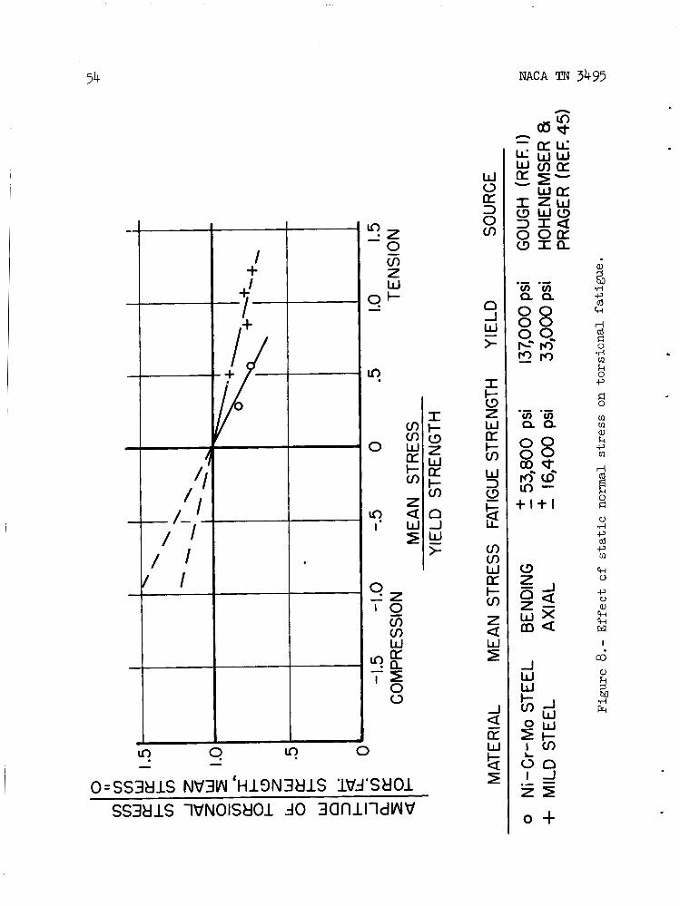
O=SS3kjlS NV3W ' H l 9 N 3 t l l S Wd'SHO1 SS3kjlS 1VNOIStlOl do 30flllldVUW
NACA TN 3495
A
I o +
rn rn e, k
k 0
I
a3

NACA TN 3495
STRESS COMBINATION
STATIC STRESS Dm
55
STATIC STRESS ON PLANES OF
MAX. ALTERNATION OF SHEAR STRESS
ALTERNATING STRESS AMPLITUDE Ca
ct-, ( 1 ) (0-
c m TENSILE C- AXIAL
4-w - (2) 0
Om COMPRESSIVE Ca AXIAL
Om TORSION ob BENDING
(5)- <d
Om TENSION TORSION
PERMISSIBLE ALTERNATING STRESS FOR SAME
FATIGUE LIFE
-+(Fig'5)
TFig'5)
TFi 0 Crn g'7
Figure 9.- Summary of e f f e c t of d i f f e r e n t combinations of s t a t i c and a l t e rna t ing s t r e s s e s on fa t igue l i f e .
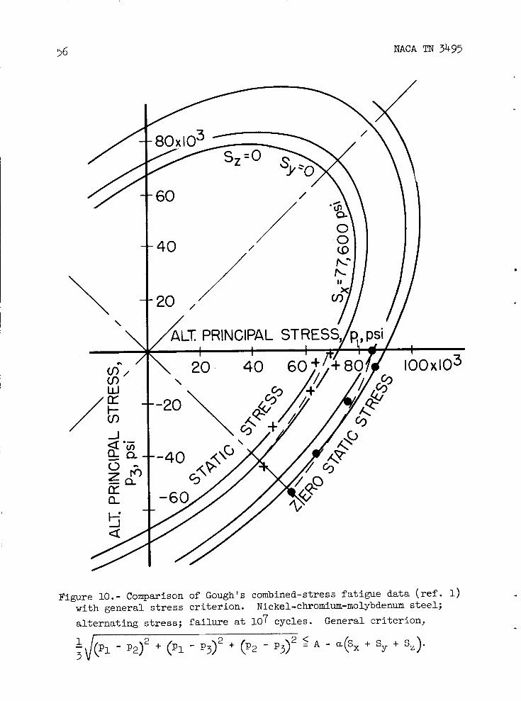
NACA TN 3495
Figure 10.- Comparison of Gough's combined-stress fa t igue data ( r e f . 1) w i t h general s t r e s s c r i t e r i o n . a l t e r n a t i n g s t r e s s ; f a i l u r e a t lo7 cycles.
Nickel-chromium-molybdenum s t e e l ; General c r i te r ion ,
-J(P1 1 - P2)2 + (PI - P3)2 + (p2 - p3) 5 A - a ( S , + sy + sz)- 3

8R NACA TN 3495 57
0
T R A N S V E ~ ~
-I 0 an / m/ W
-20
\
( a ) Cast s t e e l . Yield s t r e s s , 30 kg/IIIm2j f a i l u r e a t 10 6 cycles.
Figure 11. - Comparison of ROE and Eichinger 's combined-stress fa t igue data ( r e f . 5 ) with general s t r e s s c r i t e r i o n transformed f o r f luc tu- a t ing cycle. Minimum s t r e s s , 0.

NACA TN 3495
CI
7
cn 7 w t-
2
T R A N S V E R ~ ' cn cc
' t -
A
/
(b) Aluminum a l loy "Avional D." Yield stress, 33 kg/m2; failure a t 6 10 cycles.
Figure 11.- Concluded

NACA TN 3495
h + U
59
- \ I Y

60 NACA TN 3495
I (3 3 0 111
I- r W az
x n
1 I I I I
cl I I w 1 % a 1 0

NACA TN 3495
a al
I
3 rl
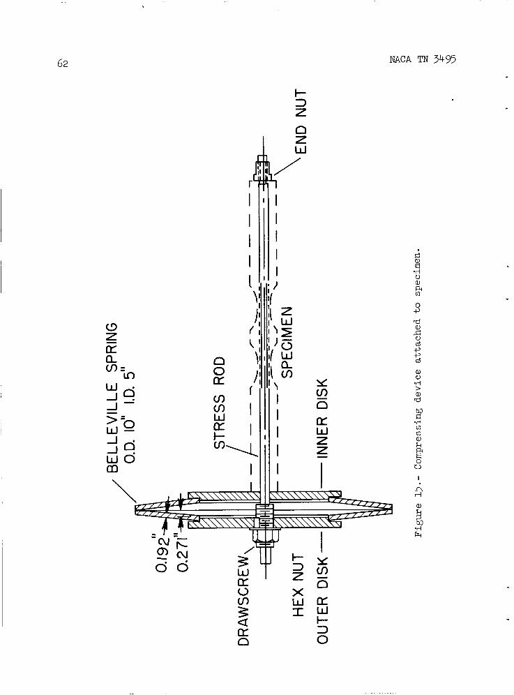
62 NACA TN 3495
I
Ln r i

NACA TN 3495 63
3,OOC
2,72C
4
m 1
I I - - - t-- + - -
I + LOADING 0 UNLOADING
- - - - - - - -
INITIAL CONDITION
C 0 .IO0 ,200 ,300 400 ,500
DEFLECTION, IN.
Figure 16.- Cal ibrat ion of B e l l e v i l l e spr ing assembly. Load held for 5 minutes a t each point; h = 1.390 inches for zero load.

64 NACA 'I" 3495
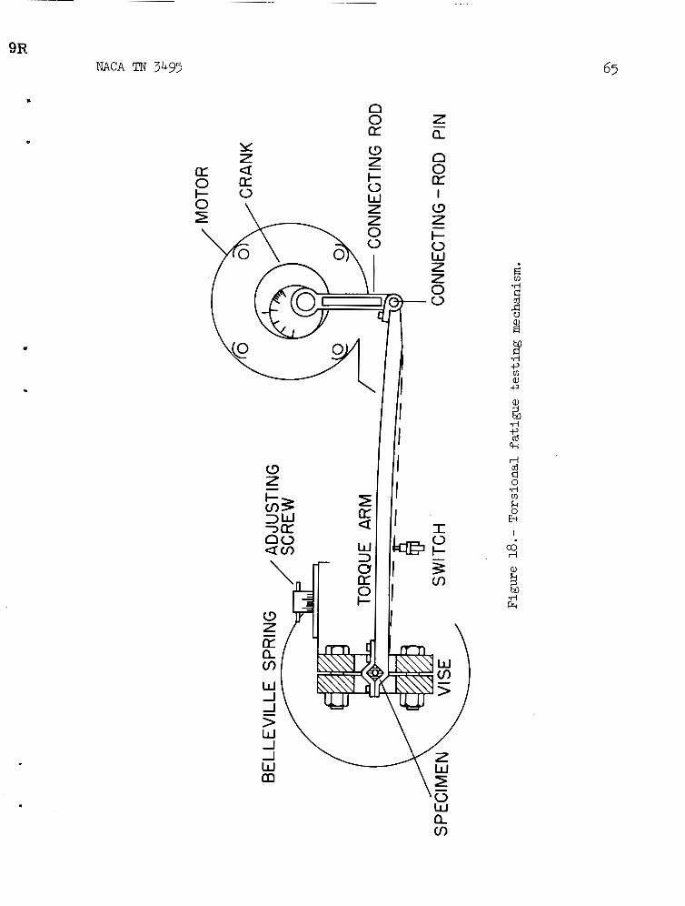
9R
I I I
NACA 'I" 3495
1L (3
z Z m a + O K 0 I - 0
(3 z t tx
W
a
w \
m
1 1 W
n 0 az I
(3 z I- 0 W z z 0 0
-
.d f, cd k
k 0 B
I
co rl
a. cn

66 NACA TN 3495
I

NACA TN 3495
0 0
0 0,
0 0 0 0-
0 0 0 0"
o + I
0 0 0 0"
0
- - c\1
!Sd 'ss3 8 1 s 1 W NOlStlOl 9N IN N8311W

68 NACA TN 3495
cn cn U I- cn
o w
O=SS3tllS NV3W 'Hl9N3t l lS 1Vd 'SUO1 SS3tllS 1VNOISttOl do 3 O f l l l l d W V
I I- (3 Z W K I- m
J W >
n
-
n m N li W U cn w Z
U
5
*iz 0 0
cf
Q
8 .- v) a 0 0 0 r6
+I -
J
X 5 a
i a
t
3 J
(D
(D -
*
a, 9 ho .rl +J
cd k
rl cd
.rl m k 0 c, d 0
m m a, k -P m
1 8 L l 0 .d c, cd c, m k 0
c, 0 a, k CH w I
rl cu
.rl $3
Frc

OR NACA TN 3495
t P
P=CURVATURE
( a ) Under tension.
V t= 2 5 I
P=2bd P
( b ) Under pure shear.
Figure 22.- Local s t r e s s e s a t elongated e l l i p t i c a l hole. (Data from r e f . 38.)
NACA - Langley Field, Va.