national advisory committee for aeronautics · r i, nati0k
TRANSCRIPT

.%
\
, ,, i i i
t
NACA TN 1311
NATIONAL ADVISORY COMMITTEE
FOR AERONAUTICS
TECHNICAL NOTE
No. 1311
FRICTION COEFFICIENTS IN A VANELESS DIFFUSER
By W. Byron Brown
Flight Propulsion Research LaboratoryCleve_nd, Ohio
YWashington
May 1947
i , ,
REPRODUCEDBYNATIONAL TECHNICALINFORMATION SERVICE
U.S.DEPARTMENTOFCOMMERCESPRINGFIELD,VA. 22161

r
i,
NATI0k<L ADVISORY C0}(_ilTTEE FOR AERONAUTICS
TECTINiC,AL EOTE NO. 1311
FRICTION CO]:LPFICIg]NTS IN A VANELESS DI_'FUSER
By W. Byron Bromn
SU_.]4ARY
Friction coe,.._-,zc_en_sfor three consta_o-area vaneless diffusers,+_-;_ _,-_, _m_,_ 7_ were deberm:'.nf:,d 2::._ :mused in conjunction with a cen ....... u:_ ......... _......... ,
static-- and total-.,._e_u .... surveys taken at sovaral ","aGm_ and from
the usual over-all me__.sureme_ts of te'.._perature_ pressure_ arJ air
.p] ._......ow, The average value of the friction coefficient through the
entire di["i'es_z _ ,,,_as a?,proximately 50 percent higher than that for
- LOWfu]_J.$,d_,,e£c_>..,,tuz'bulent _'_- in slt',oothpipes Friction coeffic:<ents
at the ........ ' ,: . 'd_.z_user entrance were about three times t1'.eoipe values In
the middle of the ......._"" " ....dz,±t_s_.L, the fz'iction coefzlclen_s agreed well with
,smooth-pipe value s,
IHTRODUCTION
The conversion of k'netic _-_"-._,......_.:.into pressv, re _-ise__in a diffuser
is accompamied by si_nificant !.osses. For certain applications -for
exam;)le, in the design of diffusers - these losses are usually cxpressed
in terms of a friction coefficient that is a m:aa.sure of' the loss .in
total pressure through the Gz:zuser.
The available data on friction coefficients in vaneless diffusers
are meager and show a rather wide scatter_ partly because of thedifficulties inherent in the determination of such coefficients and
partly because of diversity in their definition. Writers differ bya factor of 2 or &, McAdams' definition (re£erence i, p. 119) is
used in this paper. Skubatchevsky (reference 2) gives values for the
friction coefficient in conical diffusers ranging from 0.052 to 0.I00"
these values were found by the calculation of the kinetic-energy losses
between successive sections of the diffuser. These diffusers were
straight and of circular_ square, and flat-rectangular cross section.
Two ooe_fzclents were suggested in 19&l by H. W. _mons and co-workers
of Pratt & Whitney Aircraft as a measure of diffuser losse,s" one coef-
ficient was based on angt_lar momentum and the other, which is the same
as the one considered herein, was determined from the increase in
entropy e_ t.be i'luid. The entropy change was found from total- and
static-nr_-:_suro surveys in the diffuser, The data gave "entropy"
coeffici_en-t,s that covered an approximate range of 0.001 to 0,0Sg.

NACATN No. 1311
Because the avail.able data on diffuser friction coeffzcients arescarce and have a rather wide scatter and becauoe more accuratevalues would be useful in diffuser design, additional informationwas considered desirable. In the present invest_gation_ static andtotal pressures were measuredat several stations along the radiusof three constant-area vanoless diffusers, and these data were usedto determine velocity, and pressure chang_:_s.The friction coefficientwas then calculated from these changes _id the hydraulic diameter.The investigation was conducted with a centrifugal impeller of con-ventional design, and the three constant.-area diffusers_ formed bytwo successive diameter reductions of the original diffuser.
l
PROCEDURE AND APPARATUS
The experimental work was done in a variable-component compressor
_n accordance with the recommendations of reference 5, with the ex.-
ception that one radial outlet pipe was used instead of two. Data
were obtained at actual impeller tip speeds _' 800, i000, and
1200 feet per second. At speeds of S00 and lO00 feet per second,
the discharge pressure was held at i0 inches of mercury above at-
mospheric. At a speed of 1200 feet per second_ power limitations
prevented a complete load range at this discharge pressure; there-
fore each run at this speed was begun near sur_e and the load was
increased until the power limit was reached. All runs were made at
ambient-air temperature.
A conventional centrifugal impeller of 12.35-inch diameter was
used with three vanelcss diffusers in which the area perpendicular
to the radius had the constant value of 57o4 square inches. The
three diffusers were formed by successively cutting down the original
27-inch-diameter diffuser to a 24-inch and then a 20-inch diameter.
The first one-half inch of the diffuser wall was faired to make a
smooth front shroud.
The 9ver-.all measurements were made with standard instruments
at the locations recommended in reference 4. For the pressure sur-
veys in the diffuser_ static pressures were measured at points oppo-site each other on the front and rear diffuser walls_ and the arith-
metic mean of the two rGadings was taken as the static pressure atthat location. Inasmuch as the curvature of the diffuser profile is
small_ this procedure should give a satisfactory value for the static
pressure at the point. The static-pressure taps were 0.020 inch in
di_metQr and their radial location, as well as that of the total-
pressure tubos, is shown in f_gure I. The total-pressure tubes were0.094 inch in diameter with one end plugged and rounded off and a
hole 0.020 inch in diameter drilled in the side near the plugged end.

NACATN No. 1311
A total-pressure reading was taken by rotating the tubeabout its axis until a maximumreading was obtained. For eachrun, rGadings were taken with each tube at four stations that wereone-eighth, three-elghths_ five-eighths, and seven--eighths of thetotal distance from the front to the rear diffuser walls. Thetotal pressure used in the calculations is the arithmetic meanof these four readings.
l
SYM_0LS
The following symbols are used in the report:
b passage width
Cp specific heat of air at corstant pressure
D impeller diameter
I1h hydraulic diameter
f friction coefficient
g acceleration of gravity
H work done on air per unit mass
L length of flow path of air
M moment of momentln_ of air
N rotational speed
P total pressure
p static pressure
Q volume flow of air at impeller outlet
R gas constant
Re Reynolds number
r distance from axls of rotation
T total t emperaturc

NACATN No. ISII
t
U
Ur
Ut
V
W
" OC
7
AU t
P
The subscript
static temperature
resultant air velocity
radial component of a_r :'elocity
tangential component of air velocity
'impeller tip speed
weight flow of air
angle between absolute velocity a_id tangential compon6nt
ratio of' specific heat at constant pressure to specific heat
at constant volume
windage loss expressed as a decrease in U t
viscosity of air
weight density of air
o indicates the diffuser outlet.
THE ORY
Derivation of Equation _ .r Friction Coefficient
If the energy losses in a vaneiess diffuser are combined into
a single term and considered as a loss in presm_re d!e to friction,
an exter_ded form of Bernoulli's equation _ay bu u_,e6 for _,)s_-"deter-
mination of friction coefI'ic_ents. The oquatior (@:iven _n reference i_
p. ]27, in slightly di.fferent notation) is
+ :raS-+ ...... = o
where the hydraulic diameter Dh is defir:_ed as
4 X cross-sec_ior_l area
Dh = wetted perimeter
McAdams states that the pressure drop due to friction in rectangular
ducts may be calculated as for circular pipes, by using an equivalent
NACATN No. 1311 5
diameter equal to four times the hydraulic radius (reference i,p. 123). If the v_ueless diffuser is considered as a passage oflargQ aspect ratio, the application of this equation seemsappro,priate for the determination of diffuser friction coefficients.
At any radius r in the diffuser, the cross.-sectional areanormal to the flow path is 2_rb sin _ and the vetted perimeter2(2_r) sin _. Therefore,
4 _2_rb sin _) = 2bDh = 4_r sin o_ -
Also_ for flow through the diffuser,
dL = dr csc
and from the general gas equation
P
Substitution of the foregoing values for Dh, dL, and p inequation (i) and solving for f gi_ves
U dU i do°.._.
"Rgt dr p dr
f _ U 2 csc _ (2)
Rgb t
Equation (2) can be modified to give values of' f in terms of total
instead of static pressures.
Friction Coefficients from Static Pressures
The value of (l/p) (dp/dr) used in e_ation (2), is found from
the curves for the static-pressure surveys. Figure B shows a typical
curve. The velocity U is found for any radius r from its compo-
nents U r and Ut. The value of Ur is determined from the conti-
nuity equation, _ud that of the U t from the equation for angular
momentum with no heat transfer and no recirculation assu_ed.
At the impeller outlet_ the tangential velocity corrected for
windage losses is (reference 5)
6 NACATN No. 1311
,i
Ut gH . AU t= V
which becomes in dimensionless form
ut = g. _utV V 2 V
For the impeller used in this study,
AUt 25.9 ND3
V - ]_04 Q
where Q is measured at the impeller outlet. Thus, for this _mpeller,
ut _ @. _ _3.9 ND3 (3)V V2 _04 Q
With this value as a datum. U t at any other point may be foundfrom the relation derived in re_erence 6, which in the notation of
this paper is
d_MM= _ f cso_____dr (4)M b
where
M = rU t
Calculation of the friction coefficient by equation (2) for a
given set of experimental data and calculated values of U obtained
by assuming widely different values of f in equation (4) demon-
strated that the value of f from equation (2) was quite insensitive
to changes in the value of f assumed for equation (4). The value
given by the yon K_n_n equation (reference 1j pc ll9)_
I _ lO%o (ReUf) 0.40
was therefore considered sufficiently accurate for use in equation (4).
The Reynolds ntunber is expressed as
UDh0Re -

NACATN _Tc._.,_ 1511
Because U = Ur/sin % W = oUr 2_rb, and I_n = 2b, the Reynolds
number may also be written
WRe -
_r sin
A step-by-step procedure using radial increments of one-half
inch was employed in finding the values of U t and U_. Inr_smuchas the change in the quantity (csc _,)/b of equation _-4) _s small
through tile diffuser_ the value at the diffuser entrance was used
for the first increment of radius in a polnt-to-point solution,,
Then; when U t and Ur wore found for this radius_ the w_lue of
(csc _)/b was found for the end of the increment and used in the
next step.
Substitution of th_ value of p from the gon,3ral gas equation
in the continuity equation
yields
W = p2zrbU r
p2_rbU r
l_t
or
(s)Ur- g_rb
where
2
UrZ (G)U t +
t =T O_.gCp
Between the impeller and thc_ outlet measur:ng statio%
assumed cons _ant.
T o is
NACATNNo. 1511
Friction Coefficients from Total Pressures
In addition to the static-pressure surveys that were taken fo_
all runs, total-pressure surveys were taken for several runs. In_s-
much as these total-pressure readings provided independent data for
the calculation of friction factors_ they were used as a check on
the results calculated from static pressure.
The relatlon between total and static pressures may be _itten
_L_
= 2_cp%y (7)
If the value of TO (equation (6)) is substituted in equation (7)
and the resul_ is logarithmically differentiated,
dp dP 7 !__U
p - P 7-i gCpt
When Cp is replaced by 7R/(7-I)
dp dP UdU
p - P gRt
When this value of dD/p is substituted in equation (2)
Because U = (Msoc _)/r,
]_ dP
P drf _
U 2 csc
Rgbt
equation 8) can "be written
(s)
__g_t__L_- b aP
M2 8e02 _ cso _ P
f .... dr (S)r _
CO_,_UTATIONS
Friction cooffici,_nts wore determined from the static-pressure
surveys by equation (2) as foz_lows: The term (I/p)(dp/dr) was eval-
uated from the curve of the average values of the static pressure
NACATN No. 1311
throu,z!._the diffuser by dividing the pressure difference corre..s))onding to the two end points of the interval_ under considerationby [-,hcp:Le,'3su,reat the midpoint of the interval° The evaluation
•was carried out for <_u.c..:_' _,'2...i_-.ch, interval ",,radia].].yj betwe<-_'n
r = 6,5 inches and r = ro - 0.5 inch.
l{!quations (5) a_d (G) may be combined to give a quad.ratic
equation in JrJ b_t tl..esolution of this equation is long and
comp]._cated. Because the same solution can be obtained more
ossi]..F from. e,]u.;._tion(5) by successive appz'oximation.s_ this pro-
cedure ;,,asused, By use of a value of U t given by equations (3)
and (%) and with a trial value for Ur_ the equation was solved
for t, This val.ue of t was then used to obtain a revised value
of U r and. if necessary_ the process was repeated, One or two
trials were usually s_zfficient. For any one run_ U r chan_ed so
slowly through the dii'fusez _ 1:hat the value determined for the
previous .I/2-incli interv-_l could be used to find t for the next.
The va].ue of Ci_ at the im<_e].ler exit was found from
equation ('_), For points in the diffuser; the value of Ut was
dete]:.,_iued (for the sa<',m!./2._in. :i.nte:.:-valsas Ur) from the
value at the im-ge]..]erexit and equation (4.). The angle _ and
resultant velocity U were then easily found,
In the evaluation of friction coefficients from total-pressure
readings; equation (9) written in the foi-m
" r2 [" P2dr / _Rt b _\ dP
r° ,t :2see2 osoV PJrl Jh
(where the subscripts ! and 2 indicate two successive stations) was
integrated between ].imits fixed by the location of the total-
_)ressure tubcs. Because the quantities inside the parentheses are
eitb.(_r constant or change slow]_y with the radius and because each
of the successive integrations covers a rather small radial dis-
tance, the error introduced by leaving these quantities outside
the integration sign should be quite small. Integration gives
= f gl_ h L-'_ .... " <log Pl'h rlr2fl-2 _M--2_-.D _-so "_') p_ _ rl-r 2

i0 NACATN No. 1311
where the bars indicate that average values of sec2 a_ t, and(b/csc a) were used in the numerical calculations of each of theintervals. The radius with which fl-2 is associated is the averageof r I and r 2,
RESULTSANDDISCUSSION
The following table presents the radial variation in the fric-.tion coefficient computedfrom static-pressure data for the threediffusers:
"-[---_ffFh's'_F ...........................................""-,, diameter
Rad- "',,,. (in•)
ius i "'" " -)
(in.). .?:=,7.0
7.5
8.0
8.5
9.0
9.5i0.0
10•5
ii.0
11.5
12.0
12.5
Friction coefficient
a0.0098 I0.01_i,0.0093
.0071 i .0074 .0068
.0071 .005] °0047
.0024 .0040
.0031 _0033
.0031
.0033
.0031
•0032
•0033
• 0(33 0
• 0031
• 0035
• 0037
.0040
.0044
.0051
.0060
L & ".........................bAverage of 20 runs.
CAvorage of 25 runs.
For each diffuser the values of the friction coefficient at the in-
dicated radii were calculated for all tip speeds and all loads except
those in the region of flow cut-off where the data were unreliable.
Values near surge were included, though their accuracy is in some
doubt. In this region temperatur.e values probably are abnormally
high because of recirculation and therefore give abnormal values of
Ut, and therefore of f. The values shown in the table arc averages.
Average values of the friction coefficient determined from total
pressures are shown in the following table for the eight runs of the
27-inch diffuser_ in which total pressures were observed (no total-
pressure readlngs were taken in the other diffusers):
NACATN No. 1311 ii
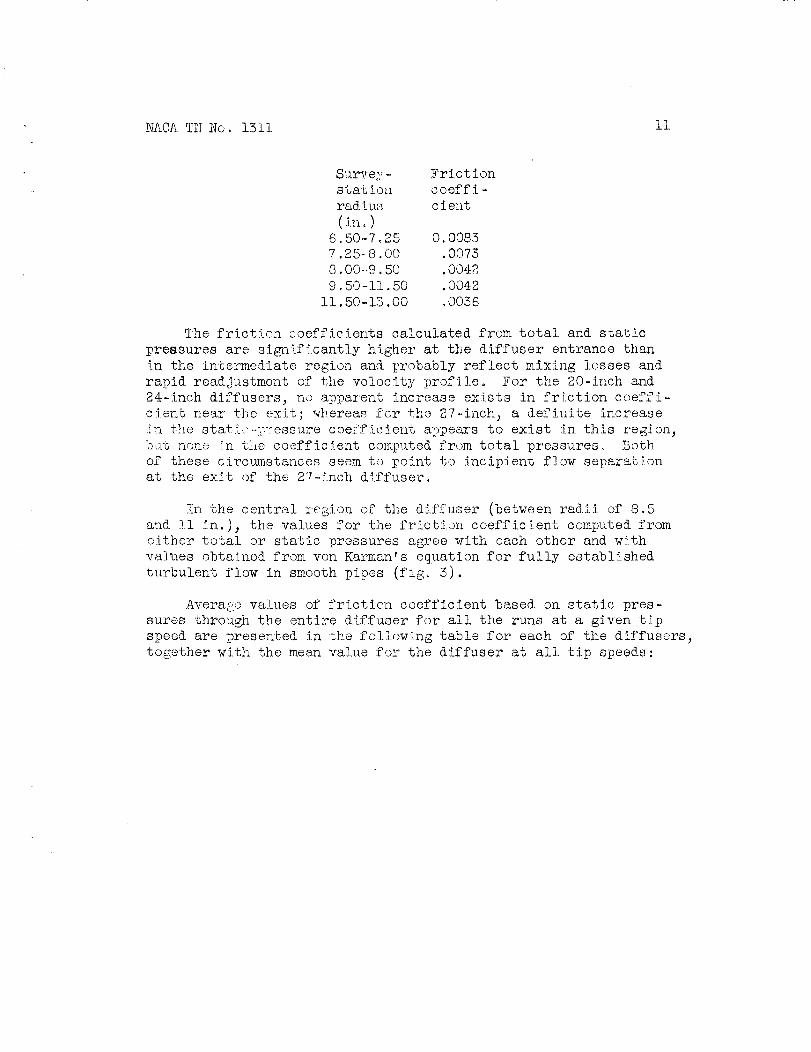
Surge?'- Frictionstatiol_ coeffi -radius cient(m.)
6,50,-7_25 O. 0085
7.25-8.00 .0075
8.00.-9.50 .004:2
9,50-11,50 .004:2
ii.50-15.00 _0056
The friction coefficients calculated from total and static
pressures are siga_ificant].y higher at the diffuser entrance than
in the intermediate region and probably reflect mixing losses and
rapid readjustment of the velocity profile, For the 20-inch and
24-inch diffusers, no apparent increase exists in friction coeffi-
cient near tLe exit; ,_hereas for %he 27-.inch_ a defiuite increase
5_._uthe stati.'-->--_'essurecoez'ficient appears to exist in this region_
bat none _n the coefficient computed from total pressures° Both
of these circumstances seem to point to incipient flow separation
at the exit of the 27-inch diffuser.
_,n the central region of the diffuser (oev_.,en radii of 8.5
and !i in.), the values for the friction coefficient computed from
either total or static pressures agree with each other and with
va]._es obtained from von I{arman's equation for fully established
turbulent flow in smooth pipes (fig. 5).
Avera_c values of friction coefficient based on static pres-
sures through the entire diffuser for all the runs at a given tip
speed are presented in the followi_ng table for each of the diffusers,
together with the mean value for the diffuser at all tip speeds:

12 NACATN No. 1511
Averagefrictioncoeff i-ci,_nt
Actual J Numbertip i ofspeed I runs(ftlsec)i
Diffuser diameter, 20 in.• i
0.0047i 800 I 8
• 0057 I 1000 1 8!
....... _0959.;.....&.?_92__4............._6Mean 0.0054 i _Total 22
Diffuser diameter_ 24 In.
o.oo 2! soo i,OOSlt lOOO 7.OOb5_ 1200 ! 6
Mean O:O05-"_t ........ [Total 20....----........... L............... L.
.......2_}_f}_22£_}L_.22_r, _7 in.0 00551 800 I i0
°0049 i tO00 t 9.0058 # 1200 i 6
•_ .
As might be expected_ the mean values of the friction coefficient
increase as the diffuser diameter decreases because the region of high
friction coefficients occupies a larger percentage of the total area
in the small diffusers than in the large. For the range of diameters
investigated in this study, the average friction coefficient for all
the diffusers was approximately 50 percent hi_er than the smooth-
pipe values.
SU_9_ARY OF RFSULTS
Friction coefficients calculated from total- and static-pressure
surveys in the three constant-area diffusers used in conjunction with
a centrifugal impeller indicated'comparatively large total-pressure
losses (three times pipe values) at the diffuser entrance, smaller
losses near the exit, and minimum losses (approximately those for
smooth-plpe flow) in the intermediate section of the diffuser. Fric-
tion coefficients computed from total pressures were significantly
larger than smooth-pipe values only at the diffuser entrance. Losses
in the flow in the midsection of the diffuser apparently were about
the same as in smooth pipes.

NACATN No. 1511 13
Average values of the static-pressure friction coefficient overthe entire flow path in the diffuser were about 50 percent higherthan those found from yon K_r_n's equation for turbulent, sm_)oth-pipe flow. The over-all friction coefficient increased with decrcaslngdiameter.
Flight Propulsion Research Laboratory,National Advisory Committeefo!' Aeronautics,
Clevelal_j Ohio, March ll_ 1947.
REFERENCES
l. McAdams_ William H.: Heat Transmission. McGraw-Hill Book Co.,
Inc., 2d ed., 1942.
, 2. Skubatchevsky, G.: Design of Supercharger Diffusers Taking into
Account the Friction Coefficients. Air Ministry Trans. No. 655.
(From Aero. Eng. (U.S.S.R.), no. 9, Sept. 1937, pp. 52-67.)
3. Ellerbrock_ Herman H., Or._ and Goldstein, Arthur W.: Principles
and Methods of Rating and Testing Centrifugal Superchargers.
NACAARR, Feb. 1942.
4. NACA Subcommittee on Supercharger Compressors: Standard Procedures
for Rating and Testing Centrifugal Compressors. NACA ARR
No. E5F13, 19A5.
5. Brown, W. Byron: Computation of the Mean Tangential Velocity
of the Air Leaving the Blade Tips of a Centrifugal Supercharger.
NACA RB No. E5G21, 19A8.
6. Polikovsky, V., and Nevelson, M.: The Performance of a Vaneless
Diffuser Fan. NACA TM No. 1058, 19A2.

O_
NACA TN No. 1 31 1
Diffuser(ino)
[]0 _3.o
0 Io. 5
KI
Fig.
0 St at i c-p ressu re tap
E] Total-pressure tube
NATIONAL ADVISOR', _C_ITTEE FOR AERONAUTICS
t-t,1
Fi gu re I. - Ai r-passage
fu ser showing
pel ler radius,
_/p11.
i
profile in impeller and
di ffuseri nst rumen t at i on
6..J 15 inches.
along
Tot al-l
p re_su re'tube
: IL
vanel ess
rad i u s.
dif-
Im-

NACA TN No. 131 1 Fig. 2
4o
39
38
o_ 37..r
&
o 36I/)
U
_' 35oO
34
33
NATIONAL ADVISORY
COMMITTEE FOR AERONAUTICS I i t
It
; 1i " i
i'" ! I
' I
i ! I i /'_
fi
/
/
/7
II
/
J I
i iI
J.I
f
J
326 8 9 I0 I1 12I_adi us, in.
fl
Figure 2. - Typical static-pressure distribution through
constant-area vaneless diffuser.
f
13

732
Z (_
Z
.012
N--
_a E
008
°_•
U 0 C 0 .-- _
.004
U °_
NA
TO
NA
LA
DV
ISO
RY
CO
fA_I
TT
EE
FO
RA
ER
ON
AU
TIC
S
06
7
X
Fric
tion
coef
ficie
nts
OS
tar
ic-p
ress
ure
surv
eys
XT
ota
I-p
ress
ure
surv
eys
....
Sm
ooth
-pip
esu
rfac
e{y
on
K_r
man
)
l/_-t
r_4
Io91
0(R
evq
r)-0
.40
__
___
___
T__
,--_
___-
-_-_
-___
89
I0
Rad
iuB
,in
.
._.._
__..I
0
I
i
I _213
Z O LN
Fig
ure
3.-
Var
iatio
nof
fric
tion
coef
fici
ents
with
radi
usin
cons
tant
-are
ava
nele
ssd
iffu
ser.
m _° L_