nasa technical note · plane waveguides radiating through a ... phased array antennas have...
TRANSCRIPT

NASA TECHNICAL NOTE NASA TN D-5914 --- L. I
REDUCTION OF MUTUAL COUPLING
N A T I O N A L AERONAUTICS A N D SPACE A D M I N I S T R A T I O N W A S H I N G T O N , D. C. M A R C H 1971
https://ntrs.nasa.gov/search.jsp?R=19710010688 2018-06-09T21:13:31+00:00Z

TECH LIBRARY KAFB, NM
19. Security Classif. (of this report)
Unclassified
1. Report No. 'IrlAsA TN D-5914
20. Security Classif. (of this page) 21. No. of Pages 22. Pr ice*
Unclassified 27 $3 -00
2. Government Accession No. I 4. T i t l e and Subtitle . Reduction of Mutual Coupling Using Perfectly Conducting Fences
7. Author(s) R. J. Mailloux
9. Performing Organization Noms and Address
Electronics Research Center Cambridge, Mass.
2. Sponsoring Agency Name and Address
National Aeronautics and Space Administration
5. Supplementary Notes
16. Abstract
3. Recipient's Cotolog No.
5. -Report Date March 1971
6. Performing Orgonization Code
8. Performing Orgonization Report No. C-132
10. Work Unit No. - - -
11. Contract or Grant No.
13. Type of Report and Period Covered
Technical Note
14. Sponsoring Agency Code
This technical note describes a theoretical and experimental study of the use of thin perfectly conduct- ing fences to reduce the mutual coupling of two parallel plane waveguides radiating through a ground plane. The two cases which are studied are E-plane coupling of parallel planes with TEM mode propagation, and H-plane coupling of parallel planes with the fundamental TE mode propagation.
The analysis presented accounts for a number of higher order modes in the waveguide apertures and uses a Fourier series approximation to the fence currents. Close agreement with experiment is demonstrated.
17. Key Words
Mutual coupling Conducting fences E-plane H-plane
18. Distribution Stotement
Unclassified - Unlimited
For sale by the National Technical Information Service, Springfield, Virginia 22151

REDUCTION OF MUTUAL COUPLING USING PERFECTLY CONDUCTING FENCES
By R. J. Mailloux NASA/Electronics Research Center
Cambridge, Massachusetts
SUMMARY
This technical note describes a theoretical and experimental study of the use of thin perfectly conducting fences to reduce the mutual coupling of two paraliel plane waveguides radiating through a ground plane. The two cases which are studied are E-plane coupling of parallel planes with TEM mode propagation, and H-plane coupling of parallel planes with the fundamental TE mode propagation.
The analysis presented accounts for a number of higher order modes in the waveguide apertures and uses a Fourier series approxi- mation to the fence currents. Close agreement with experiment is demonstrated.
INTRODUCTION
The adverse effects of mutual coupling between elements of phased array antennas have stimulated interest in methods of compensating for these effects (refs. 1-9). One of the oldest techniques for reducing mutual coupling between waveguide fed slots (ref. 10) or dipole antennas (ref. 11) is the use of thin metallic fences perpendicular to the ground plane and located between the radiating elements. Studies of thin paraliel planes extending beyond a ground plane and therefore in a fence-like arrangement have been performed by mode matching (ref. 12) for an infinite periodic structure and experimentally for a finite array (ref. 1 3 ) .
This paper presents a theoretical and experimental study of E-plane and H-plane coupling between two parallel plane wave- guides which radiate through a common ground plane. A conducting fence is placed half-way between the waveguides and the fence height is varied to determine its effect on coupled power. The analysis itself is rigorous within the limits of the mathematical model of a filimentary fence current and therefore implies the use of thin fences with rounded edges. Aside from this, the results themselves are approximate only because the series expres- sions for the aperture fields and fence current were truncated. A sufficient number of terms were taken to assure convergence of the coupled signal.

The E-plane experimental results describe the coupling bet- ween flared horns, and are of interest because of the close similarities between the coupling of these structures and the parallel planes which are studied theoretically. Though agree- ment between theory and experiment is excellent, the horns were resistively loaded to eliminate moding effects and so are best interpreted as qualitative verification of the theory. To avoid this problem, the H-plane experiment was conducted in a parallel plane simulator. These results can be compared directly with the theory and once again the agreement is excellent.
The author thanks Mr. Ronald Levenson of Northeastern University and M r . Ted Kelly of Service Technology Corporation for their help in performing the numerical computations, and Mr. F. J. LaRussa and C. L. Dunne for their work on the experi- mental phase of this study.
MATHEMATICAL FORMULATION AND SOL'JTIONS
The analysis presented in this paper consists of writing the fields in the half space in terms of contributions from the electric field in each waveguide aperture and from the current induced in the conducting fence. A mode matching technique similar to that used by Mailioux (ref. 14) for rectangular wave- guides and by Wu (ref. 15) for parallel planes is used to require field continuity at the apertures. In addition, the fence cur- rent is expanded in terms of a set of independent functions which satisfy the boundary conditions at the base and at the top of the fence. These expansions reduce the integral equations to sets of matrix equations which are solved in the general case using the method of symmetric components.
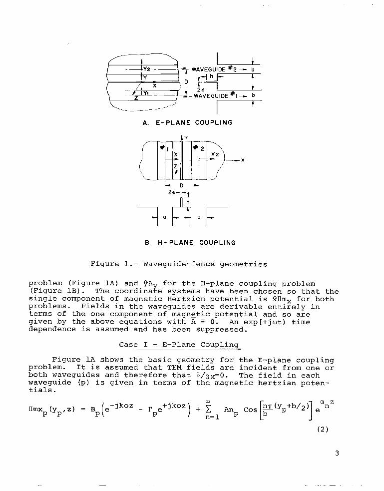
The basic geometries studied in this report are shown in Figure 1. Because of their two-dimensional nature the electro- magnetic field for each of these problems can be expanded in terms of scalar Greens functions. The half space fields are written in terms of one component of the magnetic hertzian potential de- rived from the aperture fields and a single component of the vector potential derived from the fence current and its image (see Appendix A).
- B ( r ) = V x + V(V*Fm) + ko2rm - - E(r) = -jw - [V (V-A) + ko2 A] -jwV x rm
ko
Only one component of vector potential is present in each of these problems; that component is 2AZ for the E-plane coupling
2
7 WAVEGUIDE #2 -- b
b
I I
A. E-PLANE COUPLING
B. H - P L A N E COUPLING
Figure 1.- Waveguide-fence geometries
problem (Figure 1A) and PA for the H-plane coupling problem (Figure 1 B ) . single component of magnetic Hertzion potential is 2llm, for both problems. Fields in the waveguides are derivable entirely in terms of the one component of magnetic potential and so are given by the above equations with A 3 0. An exp[+jwt) time dependence is assumed and has been suppressed.
The coordinaxe systems have been chosen so that the
Case I - E-Plane Coupling
Figure 1A shows the basic geometry for the E-plane coupling problem. It is assumed that TEM fields are incident from one or both waveguides and therefore that a / a x = O . The field in each waveguide (p) is given in terms of the magnetic hertzian poten- tials.

where
This expression includes all of the propagating and non- propagating higher order modes. In many of the cases considered the dimension b < - A , therefore all of the higher order modes are non-propagating, but one higher order mode (q=l) is allowed to propagate in one of the cases which was verified experimentally.
2
In the external space (z>O) the magnetic Hertzian pot'ential, the vector potential and the electromagnetic fields are given by:
h Az(y,z) = - -j I dz' IZ ( 2 ' ) [Ho (2) (koJ(z-z')2 + y2
2vcJ 0
Ex = By = Bz = 0
where H o ( ~ ) (r) is the Hankel function of zero order and of the second kind.
-7 In addition, - - - PO = IT x 10 henry/meter and all para- vO meters are given in terms of MKS practical units.
The aperture electric field which is used in Eq. ( 3 ) is de- rived from the magnetic potential inside the waveguides Eq. (2)
4

at z = 0. The fence current used in Eq. ( 4 ) is assumed to be concentrated at the center of the fence and to flow entirely in the 2 direction. This is consistent with the assumption of a thin fence with the top edge rounded to form a semi-cylinder.
the fence yields the integrodifferential equations (at y = +-E and z = 0 to h).
Equating the tangential electric field (Ez) to zero along
Because the fence is thin compared to any of the characteris- tic dimensions of the problem, including wavelength, these two equations are nearly identical and only the equation at Y=+E need be considered. This is equivalent to the assumption that the fence is sufficiently thin that with the two waveguides driven antisymmetrically one could insert or remove the fence without changing the fields.
This equation has a solution in the form of an integral equation.
(E ,B ) sinko (z-B)dB Z a n " Az ( E , z ) = A coskoz t B sinkoz + ko I 0 ay
The constant B is zero because of the boundary condition Ey=O at z=O. The constant A is required so that the current be set equal to zero at the top of the fence.
Continuity of the tangential electric field is assured because of the nature of the Greens functions, and continuity of the tangential magnetic field (Bx) results in the integral equa- tion below. At each aperture
This formulation has therefore resulted in a set of three coupled integral equations which describe the general problem of two parallel plane waveguides radiating through a common ground plane and with a perfectly conducting fence between the two guides.
5

SOLUTION BY THE METHOD OF SYMMETRIC COMPONENTS
Since the geometry of the fence and apertures is symmetric about y=O, the general coupling problem can be formulated in terms of the solution to the problems of coupling under symmetric and antisymmetric incident fields. The incident fields will be normalized to unity and therefore the symmetric excitation case is defined by the situation wherein both waveguides are driven with equal and opposite incident fields BS = 1 = B1 = -B2 and the antisymmetric case is defined by BA = 1 = B1 = B2. The resulting aperture equations reduce to a single equation for each of these conditions using the following relations: for the symmetric case Ani = -(-l)nAn2 E Ans and = I'2 = I'S, and for the antisymmetric case Ani = (-l)nAn2 : AnA and rl = r2 = I'A. With these definitions the fence current is zero for the case of the antisymmetric equation, and since the fence is thin its presence does not disturb the field. Therefore, only the single aperture equation remains for the antisymmetric condition. Fence and aperture equations remain coupled for the symmetric excita- tion case, but again because of symmetry only one aperture equa- tion (in addition to the fence equation) is necessary.
In order to arrive at a set of equations normalized to the incident wave of the Hertzian potential, the fence current is written in terms of the parameter CZf(z) according to the follow- ing definition:
Iz ( z ) = i2voko2Czf (z) ( 9 )
Ey is zero at z=O and so the z-derivative of the current is zero at that point. Since the current is zero at z=h it is therefore written as a truncated Fourier series of cosine func- tions.
MT c f (z) = Cmfm (z 1 Z
m= 1
where
In the case of a fence with zero thickness, the z-derivative of the current is infinite at z=h, but for the fence model used here the charge remains finite though large.
6
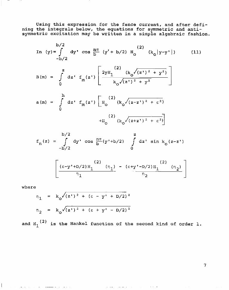
Using this expression for the fence current, and after defi- ning the integrals below, the equations for symmetric and anti- symmetric excitation may be written in a simple algebraic fashion.
(2) h a ( m ) = / dz' fm(z') [Ho (ko/(z-z')2 + c 2 )
0
b/2 Z
nn fn(z) = J dy' cos ,(y'+b/2) / dz' sin ko(z-z') -b/2 0
where
'I1 = ko/(z')2 + ( E - y' + D/2)2
and H1 (2) is the Hankel function of the second kind of order 1.
7

Symmetric Aperture Equation:
NT + A: r- cos F(y' + b/2) + f anIn(y) - f anIn(D-y)l
L -I n=l
m=l
Symmetric Fence Equation:
S 1 anfn(z)An - ko 3 fo(z) = ko 3 fo(z)r + jko n=l
MT - 2Ako cos koz + 2ko 1 Cma(m)
m= 1
Antisymmetric Aperture Equation:
L- n=l
In this form the equations are dimensionless. There are a total of Mt+Nt+2 unknowns f o r the case of symmetric excitation, where Nt is the upper limit of the terms actually used to represent the waveguide fields. coupled to the fence equation and therefore has only Nt+l unknowns. Both sets of equations are solved by requiring them to be satis- fied at Nt+l equally spaced points in the aperture (including
The antisymmetric aperture equation is not
8

y=+b/2); and for the symmetric excitation case the fence equation is required to be satisfied at Mt+l evenly spaced points on the fence (including z=O and h) .
The solution for this waveguide-fence problem for the case of arbitrary excitation (BZ # B1 # 1) can be solved in terms of the solution presented here. To accomplish this, one merely multiplies the symmetric and antisymmetric solutions by appro- priate constants in order to match the incident signals. All boundary conditions remain satisfied and so the general solution is found by multiplying the symmetric and antisymmetric solutions by the same constants and adding the results.
The most important case to consider is that of an incident wave of amplitude unity in waveguide 1 and with waveguide 2 terminated in a matched load. This case is important because the results are the coefficients of the network scattering matrix and are the most conveniently measured parameters of the coupled waveguide problem. These incident conditions are matched b taking B1 = 1 = BS + BA in Waveguide 1 and B2 = 0 = -BS + BI in Waveguide 2. Taking BS = BA = 1/2 and summing these two solu- tions completes the solution for this parasitic case. The coef- fieient of the wave propagatingtin the negative z direction in Waveguide 1 is therefore the reflection coefficient.(Sll) of this waveguide and in Waveguide 2, it is the transmission coefficient through the two port network (S12). According to the super- position principle described earlier, the complete solution to this parasitic problem is given below.
P = 1/2(rs + rA) = sll r2 = s12 = 1/2(-rs + rA) P
1 2 A = 1/2(An + An Aril and Cnp = 1/2Cn
1 S A =(1/2)(-1)n (-An + An 2 An
Because of symmetry and reciprocity, the remaining coefficients of the two-port scattering matrix are obtained directly using s22 = Sll and S21 - - S12.
case is y =
The input admittance for this parasitic
, and the power coupled into Waveguide 2 - sll 11 1 + Sll
is 20 log S12, in decibels with respect to the incident power in Waveguide 1. These parameters are of prime importance throughout this paper.
9

Case I1 - H-Plane Coupling ..
Figure 1B shows the basic geometry for the H-plane coupling problem. It is assumed that the lowest order (dominant) TE mode field is incident from the parallel plane waveguide, and there- fore that a / a = 0. This symmetry is maintained by the aperture and fence geozetry and so the entire field is independent of the coordinate y.
The field in each waveguide is therefore given in terms of the magnetic Hertzian potential:
03
+ c m= 2
where
1 amz mn a Am sin [ - (xp + a/2) e
P
and
a m =@$r - ko2 for m > 1
It is assumed that all higher order modes are attenuating; this is true for the range of a/A chosen, 1/2 < a/A < 1. Since W a r : 0, and given the existing symmetries, the only non-zero fie d components are Bx, Bz and EY. Using the same assumptions as before for this electromagnetic model of a thin fence, one obtains the half-space fields derived from the potential functions below.
J -a/2
10

(ko/(z-zt) + x2)
I ( 2 ) -H 0
(ko/(z+z')2 + x2)]
a2rrmxi 2 aA + ko IImx' - 2 -
2 Bx - ax az
-jwaII X I m - j w A az Y
E = Y
The aperture field to be used in Eq. (17) is derived from the magnetic potential inside the waveguides (Eq. 16) at z=O. Equat- ing the tangential electric field (Ey) to zero along the fence at X=E yields the following integral equation.
-a IT lmx ( E, Z )
az A (E,z) = Y
Again requiring continuity of the tangential B fields at the aper- ture yields the integrodifferential equation (evaluated at z=O).
A particular integral can be found for this equation which results in the general solution below; itself an integral equa- tion.
+ 2P
K sin k x O P 1 - kO
aAy az sin ko(Xp -X p ')dxp'
11
L . ~- -. . . . ..

Both constants K2P and K2 -1 are needed at each aperture in
This formulation has therefore resul f ed in a set of order to assure that singularigies at the edges x integrable. three coupled integral equations which describe the general problem of two parallel plane Waveguides with incident TElo modes radiating through a ground plane and with a perfectly conducting fence between the guides.
= 'a/2 are
As for the E-plane coupling problem, one can formulate the case of H-plane coupling with arbitrary incident fields in terms of the solutions of coupling under symmetric and antisymmetric incident fields. The symmetric case is defined by the situation wherein both waveguides are driven with equal incident fields BS = 1 = B1 = B2 and in the antisymmetric case by equal and opposite incident fields = 1 = B 1 = -B2. The resulting aper- ture equations reduce to a single equation for each of these conditions using the following relations: for the summetric case:
= Am1 = -(-l)mAm2, KS = K1 = K3, K! = K2 = ~5 and r s = r l = r2 , and for the antisymmetrlc case: AmA = h l = (-l)mAm2, K; = K1
for the antisymmetric case and the fence equation is neglected for this case. This procedure has reduced the set of three simul- taneous integral equations to a pair of simultaneous integral equations for the symmetric case and a single integral equation for the antisymmetric case.
The normalization of BS and BA to unity is carried through
- - -K3, K: = K2 = -K5 and rA = Y1 = r2. The fence current is zero
to the fence current by defining Cyf(z) in a manner equivalent to Eq. 9.
This current is hereAwritten as a truncated Fourier series of sine functions in the z co-orginate because the current is zero at z = 0. It flows in the y direction and so is not zero at the edge of the fence ( z = h) . In the case of a zero thickness fence this current is singular at z = h, but for the finite thick- nesses with cylindrical top studied here the current remains finite though large.
where fn(z) = sin [(2n-1) E] The integral equations are re-cast using the following definitions for numerical purposes.
12

Gn(x) = -2ko lx dx' sin ko(x-x') - 4 2
(ko,/z 2 +(&-x'+D/,) ') sin mn - (xl + a/2)) ZH1 (2)
2 2 a dx' ( koJz +(E-x'+D/~)
Ym(x,z) =
- Ho (2) (koJ(z+z')2 + E
With these definitions, one may re-write the symmetric and anti- symmetric equations as:
Symmetric Aperture Equation:
Nt + c: cos kox + Cf s i n kox + 1 CnGn(x)
n= 1
13

Symmetric Fence Equation:
I A 0
Mt 3 Jamlm j amIm + L2 At[-s in[F(x+a/2) + ~ ( x ) - -(D-x) 2 + C1 cos k x + C: s i n kox
The equations are dimensionless. There is a total of Mt + Nt + 2 unknowns for the case of symmetric equation (Mt is the total number of terms used to represent the aperture fields). The antisymmetric aperture equation is not coupled to the fence equation and so has only Mt + 2 unknowns. Both sets of equations are required to be satisfied at Mt + 2 equally spaced points in the aperture, including x = _+ a/2; and for the symmetric case the fence equation is also required to be satisfied at Nt evenly spaced points on the fence, excluding z = 0.
As for the E-plane, the solution for the case of arbitrary excitation may be obtained from the symmetric and antisymmetric solutions. The solution for an incident wave of amplitude unity in waveguide 1 and waveguide 2 terminated in a matched load is obtained by setting B1 = 1 = in waveguide 2. Taking BS = BA = 1/2 and summing the two solutions gives the solution for this parasitic case which leads to the same expressions as in equation 15 for the mode coefficients in waveguide 1 €or the E-plane case, and the coefficients T$ and Ag2 are the negative of those of Eq. 15.
Theoretical and Experimental Results
E-Plane Case.- An experiment was conducted to verify the analytical results. H-plane flared horns were used to approximate the coupled parallel planes, and because the horn 'IB" dimension was large enough to support a higher order mode, an attenuating vane was inserted in the center of each horn parallel to the H- plane and across the entire horn. This vane was found to attenuate the fundamental mode horn transmission by 3 . 7 dB, and it effec- tively eliminated all difficulties with propagation of the higher
14
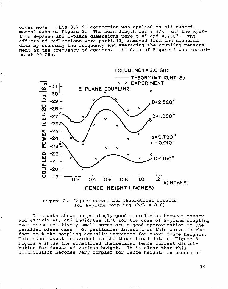
order mode. This 3.7 dB correction was applied to all experi- mental data of Figure 2 . The horn length was 8 3/4" and the aper- ture H-plane and E-plane dimensions were 5.0" and 0.790". The effects of reflections were partially removed from the measured data by scanning the frequency and averaging the coupling measure- ment at the frequency of concern. The data of Figure 2 was record- ed at 90 GHz.
N --311 v)
FREQUENCY = 9.0 GHz
THEORY (MT=13,NT=8 1 N o o EXPERIMENT --31 -
E-PLANE COUPLING 0 v)
01 0
-30 - 0
- -29-
0 0
3 -20- 0 0 0 -19 I I I 1-
~ ~~
1.0 1.2 h( INCHES 1 0.2 0.4 0.6 0.8
FENCE HEIGHT (INCHES)
- o o EXPERIMENT
E-PLANE COUPLING 0 0 01 -3v-
- -29- 0
0 0
3 -20- 0 0 0 -19 I I I 1-
~ ~~
1.0 1.2 h( INCHES 1 0.2 0.4 0.6 0.8
FENCE HEIGHT (INCHES)
Figure 2.- Experimental and theoretical results for E-plane coupling (b/X = 0.6)
This data shows surprisingly good correlation between theory and experiment, and indicates that for the case of E-plane coupling even these relatively small horns are a good approximation to the parallel plane case. Of particular interest on this curve is the fact that the coupling actually increases for short fence heights. This same result is evident in the theoretical data of Figure 3 . Figure 4 shows the normalized theoretical fence current distri- bution for fences of various height. It is clear that this distribution becomes very complex for fence heights in excess of
15

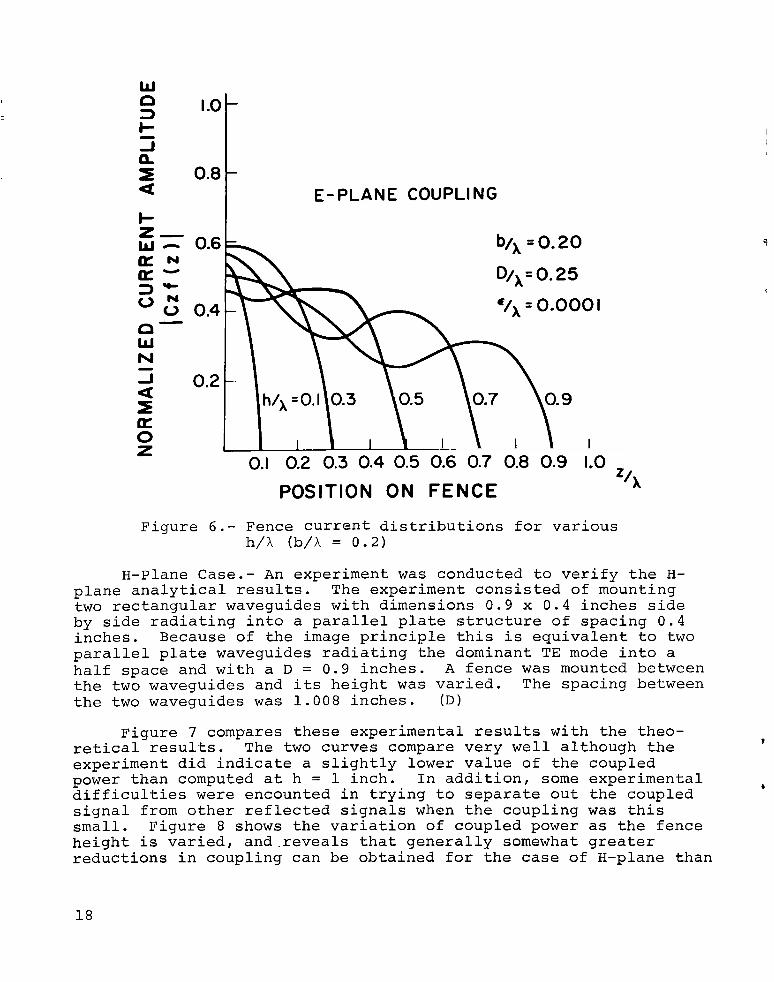
0.3 A. Figure 5 shows the coupled power for the case of much narrower parallel plane apertures. The solution is fundamentally quite different for this situation from that of Figure 3 , and the metallic fence can bring about a significant reduction in coupling for some plane separations. Figure 6 shows the fence current distribution for various fence heights and with b/A = 0.2 and D/A = 0.25. the larger h/A values are very different from those of Figure 4 for the case of much wider slot separation. In each of these cases the number of terms in the Fourier series expressions was tested for convergence of both the coupling and the fence current distribution. The values MT = 13, NT = 8 , were used for the figures and appear to guarantee convergence to within the reading accuracy of these curves.
It is noteworthy that the current distributions for
6 -16- 0
- I E- PLANE COUPLING
I 1 I I I
fi -28 v) - -27 4 -26
-25 0
-24 n n n -23 u - -22 a w -21 5 t -20 e -19 0
L
E -18 J e -17 -
D/x = 1.5
0.6
i / x = 0.OOOl
n NORMALIZED FENCE HEIGHT
Figure 3 . - Theoretical coupled power for E-plane coupling (b/X = 0.6)
16

c
- E -30-
v)
- CI
Y N
w- N
W E - PLANE COUPLING 3 n i
b/h=0.6 O / X = 1.0 €/x=o.0001
,o laor
0 0.1 0.2 0.3 0.4 0.5 0.6 0.7 0.8 0.9 1.0 z Z / X
POSITION ON FENCE
Figure 4.- Fence current distributions for various h/X (b/X = 0.2)
-16
E-PLANE COUPLING
b /X =0.2 € /A =0.0001
-10' I 1 I I 0 0.2 0.4 0.6 0.8 1.0
NORMALIZED FENCE HEIGHT
Figure 5.- Theoretical coupled power for E-plane coupling (b/A = 0.2)
W
3 I-
=E 0.8
CI I .o
n a
-
I- z- - 0.6 a~ a-
J 0.2 a
E-PLANE COUPLING
b/x = 0.20
0.1 0.2 0.3 0.4 0.5 0.6 0.7 0.8 0.9 1.0 z/x POSITION ON FENCE
Figure 6.- Fence current distributions for various h/X (b/A = 0.2)
H-Plane Case.- An experiment was conducted to verify the H- plane analytical results. two rectangular waveguides with dimensions 0.9 x 0.4 inches side by side radiating into a parallel plate structure of spacing 0.4 inches. Because of the image principle this is equivalent to two parallel plate waveguides radiating the dominant TE mode into a half space and with a D = 0.9 inches. A fence was mounted between the two waveguides and its height was varied. The spacing between the two waveguides was 1.008 inches. (D)
The experiment consisted of mounting
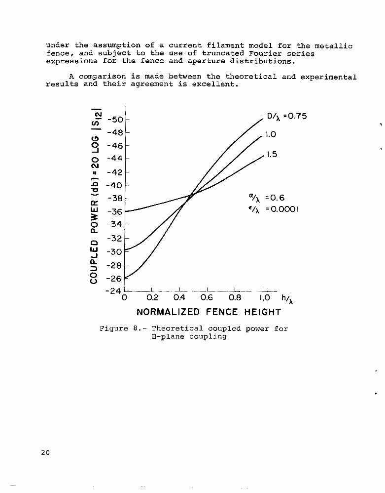
Figure 7 compares these experimental results with the theo- retical results. The two curves compare very well although the experiment did indicate a slightly lower value of the coupled power than computed at h = 1 inch. In addition, some experimental difficulties were encounted in trying to separate out the coupled signal from other reflected signals when the coupling was this small. Figure 8 shows the variation of coupled power as the fence height is varied, and.reveals that generally somewhat greater reductions in coupling can be obtained for the case of H-plane than
t
e
18

P
for a comparable E-plane case. After observing the convergence of coupled power with MT and NT, these H-plane results were obtained using MT = 3 and NT = 13. The fence current is nearly singular at the top of the fence and since this distribution is difficult to approximate by a truncated Fourier series there remain small oscillations in the fence current distribution. Since the coupled power depends only on the integral of the current no difficulties were encountered in obtaining convergence of thi’s coupled power computation.
FREQUENCY = 9.0 G Hz
ooooo THEORY ( NT=13,MT=3) EXPE R I M E N T
-
0
D - 4 0 1
a 0 n -341- / - 3 2
D = 1.008 INCHES d = 0.900 INCHES ~=0.010 INCHES
i I 1 -1 I I - 24 i 0 0.2 0.4 0.6 0.8 1.0 1.2
FENCE HEIGHT h ( I N C H E S )
Figure 7.- Experimental and theoretical results for H-plane coupling
0
Conclusion b
This study has shown that under certain conditions the use of metallic fences perpendicular to the ground plane can result in significant decreases in coupled power when placed half-way between parallel plate waveguides. The solutions are rigorous
19
I.
under the assumption of a current filament model for the metallic fence, and subject to the use of truncated Fourier series expressions for the fence and aperture distributions.
results and their agreement is excellent. A comparison is made between the theoretical and experimental
v) ‘ -501 -48 C -
-I -461
0 cu -441 1.5
-40 -
-32
-30
-28
-26 -24‘- I I I I I
0 0.2 0.4 0.6 0.8 1.0 hIX
NORMALIZED FENCE HEIGHT
Figure 8.- Theoretical coupled power for H-plane coupling
20

APPENDIX A
Expressions for the electromagnetic fields in a volume v' bounded by a surface s' are given by Levine and Schwinger in terms of the tangential electric and magnetic fields on the enclosing surface s'. The volume v' lies in the half space z 2 0 and a perfectly conducting screen divides space at the plane z = 0. The end results are given below.
The dyadic greens functions I? and r ( 2 ) are chosen to satisfy the boundary conditions at the conzucting plane
for r on the conducting plane z = 0. electric and magnetic current are given by
The surface densities of
- A - - Km(r) = -q x E(r) 1
A
where q is the normal pointing into s ' .
interpreted in terms of the image principle)
The dyadic greens L functions are given by Levine and Schwinger (and are easily
21

- - where r(O) (r,r') is the free space dyadic greens function and is written:
where
and
and - u is the unit dyad.
These equations may be written in a more convenient form using the relation
and
+ [ V G ( r , F * ) x K(F') + V G ( r , r " ) x KIM (F)] ds'
where
--IM K (F') = K (F') (E - 229 - 299)
22

and
- (3) (U -284) Em*M(:') = Km -
and
= 4 x - x ' ) 2 + (y-y'I2 + ( z + z ' ) 2
These relations are in a form which allow interpretation in terms of conventional potential functions. In doing this, it is convenient to restrict the formulation immediately to the case in point; wherein apertures are cut into the ground plane. When this is done, the contributions from the electric current on the ground plane vanish because of the form of the Greens Functions and the only electric current contributions which remain are due to the integrals over the fence and its image. The magnetic cur- rent contributions arise from the tangential electric field in the apertures where the magnetic current and its image current add in phase. One may therefore define the following potential functions for the half plane z 2 0. -
- - -jko I r-r' I
dSp ' e 1 ---I r r 1
' ( 2 x E ( r ' ) ) -
2lTw p sp nm(F) =
where
2 2 Ir-r'l = Jz2 + (x-x') + (y-y')
and
r
-I- r
- - -ik Ir-rl I fi x E(?) e o IF-? I
J
23
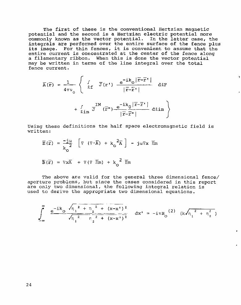
The first of these is the conventional Hertzian magnetic potential and the second is a Hertzian electric potential more commonly known as the vector potential. integrals are performed over the entire surface of the fence plus its image. entire current is concentrated at the center of the fence along a filamentary ribbon. may be written in terms of the line integral over the total fence current.
In the latter case, the
For thin fences, it is convenient to assume that the
When this is done the vector potential
A(F) =
Using these written:
1 4 5
r Rf
- - e -ikolr-r' I
d RF
definitions the half space electromagnetic field is
0
2 - V x Z + V(V Em) + ko IIm
The above are valid for the general three dimensional fence/ aperture problems, but since the cases considered in this report are only two dimensional, the following integral relation is used to derive the appropriate two dimensional equations.
+ (X-X')2 + (X-xq2
-iko /q12 + T12 2
dx' = - i n H 0 2
n2
24

REFERENCES
1. Hannan, P. W.; Lerner, D. S . ; and Knittel, G. H.: Impedance Matching a Phased-Array Antenna over Wide Scan Angles by Connecting Circuits. IEEE Transactions on Antennas and Propagation, Vol. AP-13, No. 1, January 1965, pp. 28-34.
2. Magill, E. G.; and Wheeler, H. A.: Wide Angle Impedance Matching of a Planar Array Antenna by a Dielectric Sheet. IEEE Transactions on Antennas and Propagation, AP-14, January 1966, pp. 49-53.
3. Wong, N. S. et al: Investigation of Use of Superimposed Surface Wave Modes. AD-631 936, Final Report on Contract AF 19 (628) - 4984, Technical Report, AFCRL-66-200-1, February 28, 1966.
tion through Contiguous Element Coupling. IEEE Transactions on Antennas and Propagation, Vol. AP-14, No. 5, September
4 . Amitay, N.: Improvement of Planar Array Match by Compensa-
1966, pp. 580-585. 5. Lee, S. W.: Impedance Matching of an Infinite Phased Array
by Dielectric Sheets. Electronics Letters 2, October 1966, pp. 366-368.
Rectangular Waveguide Phased Array. International Symposium on Antennas and Propagation, Palo Alto, California, December 1966.
7. Amitay, N.; Butzien, P. E.; and Heidt, R. C.: Match Opti- mization of a Two-Port Phased Array Antenna Element. IEEE Transactions on Antennas and Propagation, Vol. AP-16, No. 1, January 1968, pp. 47-57.
8 . Wu, C. P.; and Galindo, V.: Surface-Wave Effects on Di- electric Sheathed Phased Arrays of Rectangular Waveguides. The Bell System Technical Journal, January 1968, pp. 117-142.
9. Hannan, P. W.; and Litt, S. P.: Capacitive Ground Plane for a Phased Array Antenna. 1968 IEEE Professional Group on Antennas and Propagation, International Symposium, September 9, 1968.
6. Galindo, V.; and Wu, C. P.: Dielectric Loaded and Covered
10. Edelberg, S . ; and Oliner, A. A.: Mutual Coupling Effects
Transactions on Antennas and Propagation, Vol. AP-8, July 1960, pp. 360-367.
11. Brennecke, N. R.; and Moule, W. N.: Use of Fences to Opti- mize Operating Impedance of Phase Arrays, Using an Improved Measuring Technique. PTGAP International Symposium Digest, September 21, 1964, pp. 134-142.
4 in Large Antenna Arrays 11: Compensation Effects. IRE
25
I

1 2 . Dufor t , E . C . : Design of Corrugated P l a t e s f o r Phased Array Matching. IEEE Transac t ions on Antennas and Propaga- t i o n , V o l . AP-16, N o . 1, January 1968, pp. 37-46.
13. Al len , C . C. : Mutual Coupling E f f e c t s i n Phased Array Antennas. T h i r t e e n t h Annual Symposium, U S A F Antenna Research and Development Program, U n i v e r s i t y of I l l i n o i s , October 1 4 , 1963.
1 4 . Mailloux, R. J.: Radia t ion and Hear-Field Coupling Between Two C o l l i n e a r Open-Ended Waveguides. IEEE Transac t ions on Antennas and Propagat ion, V o l . AP-17, N o . 1, January 1 9 6 9 , pp. 49-55.
Waveguides i n F i n i t e Arrays. Radio Sc ience , V o l . 4 , No. 3, March 1 9 6 9 , pp. 245-254.
15 . Wu, C . P . : Numerical So lu t ions f o r t h e Coupling Between
,
2 6 NASA-Langley, 1971 - 7 C-132

NATIONAL AERONAUTICS AND SPACE ADMINISTRAI ION
WASHINGTON, D. C. 20546
OFFICIAL BUSINESS PENALTY FOR PRIVATE U S E $300 \
FIRST CLASS MAIL
POSTAGE A N D FEES PAID NATIONAL AERONAUTICS AND
SPACE ADMINISTRATION
05U 001 32 5 1 30s 71070 00903 A I R F O R C E WEAPONS LABORATORY /WLOL/ KIRTLAND AFBI NEW M E X I C O 87117
ATT E. LOU BOWMAN, CHIEFpTECH. L I B R A R Y
If Undeliverable (Section 158 Postal Manual) Do Not Return
__ _ -
“The aeronautical and space activities of the United States shall be conducted so as t o contribute , . . t o the expansion of hunzan knowl- edge of phenoniena in the atiiiosphere and space. T h e Adniinistration shall provide f o r the widest practicable and appropriate dissemination of inforiiiation concerning its activities and the resalts thereof.”
-NATIONAL AERONAUTICS A N D SPACE ACT OF 1958
NASA SCIENTIFIC AND TECHNICAL PUBLICATIONS
TECHNICAL REPORTS: Scientific and technical information considered important, complete, and a lasting contribution to existing knowledge.
TECHNICAL NOTES: Information less broad in scope but nevertheless of importance as a contribution to existing knowledge.
TECHNICAL MEMORANDUMS : Information receiving limited distribution because of preliminary data, security classifica- tion, or other reasons.
TECHNICAL TRANSLATIONS: Information published in a foreign language considered to merit NASA distribution in English.
SPECIAL PUBLICATIONS: Information derived from or of value to NASA activities. Publications include conference proceedings, monographs, data compilations, handbooks, sourcebooks, and special bibliographies.
TECHNOLOGY UTILIZATION PUBLICATIONS: Information on technology used by NASA that may be of particular interest in commercial and other non-aerospace applications. Publications include Tech Briefs, Technology Utilization Reports and Technology Surveys.
CONTRACTOR REPORTS: Scientific and technical information generated under a NASA contract or grant and considered an important contribution to existing knowledge.
Details on the availability of these publications may be obtained from:
SCIENTIFIC AND TECHNICAL INFORMATION OFFICE
NATIONAL AERONAUTICS AND SPACE ADMINISTRATION Washington, D.C. PO546
1