stimulated brillouin scattering in nanoscale silicon step...
TRANSCRIPT
Stimulated Brillouin scattering innanoscale silicon step-index waveguides:a general framework of selection rules
and calculating SBS gain
Wenjun Qiu,1 Peter T. Rakich,2 Heedeuk Shin,2 Hui Dong,3 MarinSoljacic,1 and Zheng Wang3,∗
1Department of Physics, Massachusetts Institute of Technology, Cambridge, MA 02139 USA2Department of Applied Physics, Yale University, New Haven, CT 06520 USA
3Department of Electrical and Computer Engineering, University of Texas at Austin, Austin,TX 78758 USA
Abstract: We develop a general framework of evaluating the StimulatedBrillouin Scattering (SBS) gain coefficient in optical waveguides via theoverlap integral between optical and elastic eigen-modes. This full-vectorialformulation of SBS coupling rigorously accounts for the effects of bothradiation pressure and electrostriction within micro- and nano-scale waveg-uides. We show that both contributions play a critical role in SBS couplingas modal confinement approaches the sub-wavelength scale. Throughanalysis of each contribution to the optical force, we show that spatialsymmetry of the optical force dictates the selection rules of the excitableelastic modes. By applying this method to a rectangular silicon waveguide,we demonstrate how the optical force distribution and elastic modal profilesjointly determine the magnitude and scaling of SBS gains in both forwardand backward SBS processes. We further apply this method to the study ofintra- and inter-modal SBS processes, and demonstrate that the couplingbetween distinct optical modes are necessary to excite elastic modes with allpossible symmetries. For example, we show that strong inter-polarizationcoupling can be achieved between the fundamental TE- and TM-like modesof a suspended silicon waveguide.
© 2013 Optical Society of America
OCIS codes: (190.2640) Stimulated scattering, modulation, etc.; (220.4880) Optomechanics;(190.4390) Nonlinear optics, integrated optics; (130.2790) Guided waves.
References and links1. R. Y. Chiao, C. H. Townes, and B. P. Stoicheff, “Stimulated Brillouin scattering and coherent generation of
intense hypersonic waves,” Phys. Rev. Lett. 12, 592–595 (1964).2. P. Dainese, P. Russell, N. Joly, J. Knight, G. Wiederhecker, H. Fragnito, V. Laude, and A. Khelif, “Stimulated
Brillouin scattering from multi-ghz-guided acoustic phonons in nanostructured photonic crystal fibres,” Nat.Phys. 2, 388–392 (2006).
3. A. Kobyakov, M. Sauer, and D. Chowdhury, “Stimulated Brillouin scattering in optical fibers,” Adv. Opt. Pho-tonics 2, 1–59 (2010).
4. M. S. Kang, A. Nazarkin, A. Brenn, and P. S. J. Russell, “Tightly trapped acoustic phonons in photonic crystalfibres as highly nonlinear artificial raman oscillators,” Nat. Phys. 5, 276–280 (2009).
#197459 - $15.00 USD Received 12 Sep 2013; revised 18 Nov 2013; accepted 18 Nov 2013; published 12 Dec 2013(C) 2013 OSA 16 December 2013 | Vol. 21, No. 25 | DOI:10.1364/OE.21.031402 | OPTICS EXPRESS 31402
5. R. Pant, C. G. Poulton, D.-Y. Choi, H. Mcfarlane, S. Hile, E. Li, L. Thevenaz, B. Luther-Davies, S. J. Madden,and B. J. Eggleton, “On-chip stimulated Brillouin scattering,” Opt. Express 19, 8285–8290 (2011).
6. M. Tomes and T. Carmon, “Photonic micro-electromechanical systems vibrating at x-band (11-ghz) rates,” Phys.Rev. Lett. 102, 113601 (2009).
7. A. Byrnes, R. Pant, E. Li, D. Choi, C. G. Poulton, S. Fan, S. Madden, B. Luther-Davies, and B. J. Eggleton,“Photonic chip based tunable and reconfigurable narrowband microwave photonic filter using stimulated Bril-louin scattering,” Opt. Express 20, 18845–18854 (2012).
8. Z. Yu and S. Fan, “Complete optical isolation created by indirect interband photonic transitions,” Nat. Photonics3, 91–94 (2009).
9. M. S. Kang, A. Butsch, and P. S. J. Russell, “Reconfigurable light-driven opto-acoustic isolators in photoniccrystal fibre,” Nat. Photonics 5, 549–553 (2011).
10. C. G. Poulton, R. Pant, A. Byrnes, S. Fan, M. J. Steel, and B. J. Eggleton, “Design for broadband on-chipisolator using stimulated Brillouin scattering in dispersion-engineered chalcogenide waveguides,” Opt. Express20, 21235–21246 (2012).
11. Z. Zhu, D. J. Gauthier, and R. W. Boyd, “Stored light in an optical fiber via stimulated Brillouin scattering,”Science 318, 1748–1750 (2007).
12. Y. Okawachi, M. S. Bigelow, J. E. Sharping, Z. Zhu, A. Schweinsberg, D. J. Gauthier, R. W. Boyd, and A. L.Gaeta, “Tunable all-optical delays via Brillouin slow light in an optical fiber,” Phys. Rev. Lett. 94, 153902 (2005).
13. K. Y. Song, M. Herraez, and L. Thevenaz, “Observation of pulse delaying and advancement in optical fibersusing stimulated Brillouin scattering,” Opt. Express 13, 82–88 (2005).
14. K. Y. Song, K. S. Abedin, K. Hotate, M. G. Herraez, and L. Thevenaz, “Highly efficient Brillouin slow and fastlight using As2Se3 chalcogenide fiber,” Opt. Express 14, 5860–5865 (2006).
15. R. Pant, M. D. Stenner, M. A. Neifeld, and D. J. Gauthier, “Optimal pump profile designs for broadband sbsslow-light systems,” Opt. Express 16, 2764–2777 (2008).
16. R. Pant, A. Byrnes, C. G. Poulton, E. Li, D. Choi, S. Madden, B. Luther-Davies, and B. J. Eggleton, “Photonic-chip-based tunable slow and fast light via stimulated Brillouin scattering,” Opt. Lett. 37, 969–971 (2012).
17. T. Kurashima, T. Horiguchi, and M. Tateda, “Distributed-temperature sensing using stimulated Brillouin scatte-ring in optical silica fibers,” Opt. Lett. 15, 1038–1040 (1990).
18. A. Schliesser, R. Riviere, G. Anetsberger, O Arcizet, and T. J. Kippenberg, “Resolved-sideband cooling of amicromechanical oscillator,” Nat. Phys. 4, 415–419 (2008).
19. G. Bahl, M. Tomes, F. Marquardt, and T. Carmon, “Observation of spontaneous Brillouin cooling,” Nat. Phys. 8,203–207 (2012).
20. W. C. Jiang, X. Lu, J. Zhang, and Q. Lin “High-frequency silicon optomechanical oscillator with an ultralowthreshold,” Opt. Express 20, 15991–15996 (2012).
21. H. O. Hill, B. S. Kawasaki, and D. C. Johnson, “CW Brillouin laser,” Appl. Phys. Lett. 28, 608–609 (1976).22. I. V. Kabakova, R. Pant, D. Choi, S. Debbarma, B. Luther-Davies, S. J. Madden, and B. J. Eggleton, “Narrow
linewidth Brillouin laser based on chalcogenide photonic chip,” Opt. Lett. 38, 3208–3211 (2013).23. Y. R. Shen, N. Bloembergen, “Theory of stimulated Brillouin and Raman scattering,” Phys. Rev. 137, A1787–
A1805 (1965).24. R. Boyd, Nonlinear Optics, 3rd ed. (Academic, 2009).25. G. Agrawal, Nonlinear Fiber Optics, 4th ed. (Academic, 2006).26. J. Botineau, E. Picholle, and D. Bahloul, “Effective stimulated Brillouin gain in singlemode optical fibres,”
Electron. Lett. 31, 2032–2034 (1995).27. J. Wang, Y. Zhu, R. Zhang, and D. J. Gauthier, “FSBS resonances observed in a standard highly nonlinear fiber,”
Opt. Express 19, 5339–5349 (2011).28. A. H. McCurdy, “Modeling of stimulated Brillouin scattering in optical fibers with arbitrary radial index profile,”
J. Lightwave Technol. 23, 3509 (2005).29. X. Huang and S. Fan, “Complete all-optical silica fiber isolator via stimulated Brillouin scattering,” J. Lightwave
Technol. 29, 2267–2275 (2011).30. M. S. Kang, A. Brenn, and P. S. J. Russell, “All-optical control of gigahertz acoustic resonances by forward
stimulated interpolarization scattering in a photonic crystal fiber,” Phys. Rev. Lett. 105, 153901 (2010).31. P. T. Rakich, C. Reinke, R. Camacho, P. Davids, and Z. Wang, “Giant enhancement of stimulated Brillouin
scattering in the subwavelength limit,” Phys. Rev. X 2, 011008 (2012).32. H. Shin, W. Qiu, R. Jarecki, J. A. Cox, R. H. Olsson III, A. Starbuck, Z. Wang, and P. T. Rakich, “Tailorable
stimulated Brillouin scattering in nanoscale silicon waveguides,” Nat. Commun. 4, 1944 (2013).33. R. Van Laer, D. Van Thourhout, and R. Baets, “Strong stimulated Brillouin scattering in an on-chip silicon slot
waveguide,” in CLEO: Science and Innovations, San Jose, CA, 9–14 June 2013 .34. P. T. Rakich, M. A. Popovi, M. Soljacic, and E. P. Ippen, “Trapping, corralling and spectral bonding of optical
resonances through optically induced potentials,” Nat. Photonics 1, 658–665 (2007).35. M. Eichenfield, C. P. Michael, R. Perahia, and O. Painter, “Actuation of micro-optomechanical systems via
cavity-enhanced optical dipole forces,” Nat. Photonics 1, 416–422 (2007).36. T. J. Kippenberg and K. J. Vahala, “Cavity optomechanics: Back-action at the mesoscale,” Science 321, 1172–
#197459 - $15.00 USD Received 12 Sep 2013; revised 18 Nov 2013; accepted 18 Nov 2013; published 12 Dec 2013(C) 2013 OSA 16 December 2013 | Vol. 21, No. 25 | DOI:10.1364/OE.21.031402 | OPTICS EXPRESS 31403
1176 (2008).37. M. Eichenfield, J. Chan, R. M. Camacho, K. J. Vahala, and O. Painter, “Optomechanical crystals,” Nature 462,
78–82 (2009).38. G. S. Wiederhecker, L. Chen, A. Gondarenko, and M. Lipson, “Controlling photonic structures using optical
forces,” Nature 462, 633–636 (2009).39. M. Eichenfield, J. Chan, A. H. Safavi-Naeini, K. J. Vahala, and O. Painter, “Modeling dispersive coupling and-
losses of localized optical andmechanical modes in optomechanicalcrystals,” Opt. Express 17, 20078–20098(2009).
40. M. Li, W. H. P. Pernice, and H. X. Tang, “Tunable bipolar optical interactions between guided lightwaves,” Nat.Photonics 3, 464–468 (2009).
41. J. Roels, I. D. Vlaminck, L. Lagae, B. Maes, D. V. Thourhout, and R. Baets, “Tunable optical forces betweennanophotonic waveguides,” Nat. Nanotechnol. 4, 510–513 (2009).
42. Q. Lin, J. Rosenberg, D. Chang, R. Camacho, M. Eichenfield, K. J. Vahala, and O. Painter, “Coherent mixing ofmechanical excitations in nano-optomechanical structures,” Nat. Photonics 4, 236–242 (2010).
43. D. Royer and E. Dieulesaint, Elastic Waves in Solids I: Free and Guided Propagation (Springer, 2000).44. Z. Yu and S. Fan, “Complete optical isolation created by indirect interband photonic transitions,” Nat. Photonics
3, 91–94 (2008).45. P. T. Rakich, P. Davids, and Z. Wang, “Tailoring optical forces in waveguides through radiation pressure and
electrostrictive forces,” Opt. Express 18, 14439–14453 (2010).46. M. L. Povinelli, M. Loncar, M. Ibanescu, E. J. Smythe, S. G. Johnson, F. Capasso, and J. D. Joannopoulos,
“Evanescent-wave bonding between optical waveguides,” Opt. Lett. 30, 3042–3044 (2005).47. P. T. Rakich, Z. Wang, and P. Davids, “Scaling of optical forces in dielectric waveguides: rigorous connection
between radiation pressure and dispersion,” Opt. Lett. 36, 217–219 (2011).48. W. Qiu, P. Rakich, M. Soljacic, and Z. Wang, “Stimulated Brillouin scattering in slow light waveguides,”
arXiv1210.0738 (2012).49. S. Chandorkar, M. Agarwal, R. Melamud, R. Candler, K. Goodson, and T. Kenny, “Limits of quality factor in
bulk-mode micromechanical resonators,” in IEEE 21st International Conference on Micro Electro MechanicalSystems, 2008. MEMS 2008 (2008), pp. 74–77.
50. E. Dieulesaint and D. Royer, Elastic Wvaes in Solids II: Generation, Acousto-Optic Interaction, Applications(Springer, 2000).
51. J. P. Gordon, “Radiation forces and momenta in dielectric media,” Phys. Rev. A 8, 14–21 (1973).52. P. W. Milonni and R. W. Boyd, “Momentum of light in a dielectric medium,” Adv. Opt. Photonics, 2, 519–553
(2010).53. S. G. Johnson, M. Ibanescu, M. A. Skorobogatiy, O. Weisberg, J. D. Joannopoulos, and Y. Fink, “Perturbation
theory for Maxwell’s equations with shifting material boundaries,” Phys. Rev. E 65, 066611 (2002).54. M. A. Hopcroft, W. D. Nix, and T. W. Kenny, “What is the Youngs Modulus of silicon?,” J. Microelectromech.
Syst. 19, 229–238 (2010).55. L. S. Hounsome, R. Jones, M. J. Shaw, and P. R. Briddon, “Photoelastic constants in diamond and silicon,” Phys.
Status Solidi A 203, 3088–3093 (2006).56. R. Shelby, M. Levenson, and P. Bayer, “Guided acoustic-wave Brillouin scattering,” Phys. Rev. B 31, 5244–5252
(1985).57. R. Shelby, M. Levenson, and P. Bayer, “Resolved forward Brillouin scattering in optical fibers,” Phys. Rev. Lett.
54, 939-942 (1985).58. R. Pant, A. Byrnes, C. G. Poulton, E. Li, D.-Y. Choi, S. Madden, B. Luther-Davies, and B. J. Eggleton, “Photonic-
chip-based tunable slow and fast light via stimulated Brillouin scattering,” Opt. Lett. 37, 969–971 (2012).59. A. Byrnes, R. Pant, E. Li, D.-Y. Choi, C. G. Poulton, S. Fan, S. Madden, B. Luther-Davies, and B. J. Eggle-
ton, “Photonic chip based tunable and reconfigurable narrowband microwave photonic filter using stimulatedBrillouin scattering,” Opt. Express 20, 18836–18845 (2012).
60. J. Li, H. Lee, T. Chen, and K. J. Vahala, “Characterization of a high coherence, Brillouin microcavity laser onsilicon,” Opt. Express 20, 20170–20180 (2012).
1. Introduction
Stimulated Brillouin Scattering (SBS) is a third-order nonlinear process that produces efficientcoupling between traveling-wave photons and phonons [1,2]. Nonlinear coupling through SBShas been widely studied, yielding applications such as optical frequency conversion [3–5], ra-dio frequency signal processing [6, 7], optical isolators [8–10] stopped light [11], slow light[12–16], distributed temperature sensing [17], cooling [18,19], oscillator [20], and novel laserssources [21, 22]. Brillouin nonlinearities, which are known to be among the strongest nonlin-earities in optical fibers, also show promise as the basis for a number of chip-scale signal pro-
#197459 - $15.00 USD Received 12 Sep 2013; revised 18 Nov 2013; accepted 18 Nov 2013; published 12 Dec 2013(C) 2013 OSA 16 December 2013 | Vol. 21, No. 25 | DOI:10.1364/OE.21.031402 | OPTICS EXPRESS 31404
cessing applications through the use of highly nonlinear chalcogenide waveguides [5,7,10,16].At a basic level, the versatility of Brillouin processes springs from our ability to understandand manipulate this powerful form of photon-phonon coupling in a large variety of waveguidesystems.
Over the past several decades, various conceptually simple and useful methods have beenemployed to predict the strength of SBS coupling within guided-wave systems based on modaloverlap integrals [4, 9, 23–30]. Through these treatments, which have proven remarkably ac-curate for the prediction of SBS in microscale waveguides and fibers, one is often able viewBrillouin coupling as arising from intrinsic (or bulk) material nonlinearities. Note that the bulkBrillouin nonlinearity is conventionally defined by a combination of the dispersive, mechani-cal, and photoelastic properties of a given nonlinear medium [23–25]. This leads to the simpleand intuitive notion that Brillouin nonlinearities may be viewed as an intrinsic third-ordernonlinearity, akin to Raman and electronic nonlinearities. Within this paradigm, one expectsSBS coupling to scale inversely with waveguide modal area, yielding higher nonlinearities aswaveguide dimensions are reduced. This paradigm works remarkably well in predicting SBSnonlinearities in a wide variety of fiber and waveguide systems. However, these conventionalnotions of Brillouin coupling (as a bulk material nonlinearity) fail to predict SBS couplingwithin nanophotonic silicon waveguides. Despite the radical enhancement of both Raman andelectronic nonlinearities in silicon nanophotonics, stimulated Brillouin scattering has entirelyeluded observation in silicon waveguides for over a decade, due to the more complex nature ofphonon confinement and photon-phonon coupling within nanoscale silicon waveguides [31].
Only recently, with the realization of hybrid photonic-phononic waveguides, has it been pos-sible to demonstrate radically enhanced and engineerable forms of stimulated Brillouin scat-tering in silicon nanophotonics [32]. Within such nanoscale silicon waveguides, strong light-boundary interactions were found to have a significant impact on photon-phonon coupling. Forexample, sub-wavelength confinement within high-index-contrast silicon waveguides give riseto new radiation pressure mediated forms of SBS [31–33]. Moreover, elastic wave displace-ments at the discontinuous boundaries of high-index-contrast waveguides also give rise to non-linear polarization-currents that yield significant contribution to the overall Brillouin nonlinear-ity [31]. These new contributions to SBS coupling require a treatment that accurately capturesthe full-vectorial nature of these boundary interactions [31], and accounts for the emergence ofstrong radiation pressure induced couplings, which have been shown to play a crucial role inthe dynamics of a range of recent nano-optomechanical systems [34–42].
In this article, we present a general method of calculating SBS gain that accurately capturesthese physics of SBS coupling due to electrostriction and boundary induced radiation pres-sures in nanoscale silicon photonics. More generally, this method is applicable to the studyof Brillouin nonlinearities in any system consisting of transparent dielectric media with anycharacteristic length-scale. Through this treatment, we develop the general form of the opticalforce distributions produced by the two interacting optical eigen-modes (e.g. pump and Stokesmodes) and the elastic eigen-modes which mediate photon-phonon coupling. Most previousformulations of SBS treat the optical modes as linearly polarized and often simplify the elasticmode as a scalar density wave. However, we show that the vector nature and the nontrivialspatial distribution of both optical and elastic eigenmodes have to be fully considered. In whatfollows, the time dependent forms of the electrostrictive and radiation pressure induced forcesare used to formulate analytical expressions for the overall Brillouin gain via an overlap in-tegral with the guided elastic-wave eigenmodes. Full-vectorial formulations of the elastic andelectromagnetic fields allow the use of the most general form of dielectric and elastic tensors,necessary to treat complex nanophotonic systems in this paper. Both forward-SBS (FSBS) andbackward-SBS (BSBS) geometries are explicitly treated, and both intra-modal and inter-modal
#197459 - $15.00 USD Received 12 Sep 2013; revised 18 Nov 2013; accepted 18 Nov 2013; published 12 Dec 2013(C) 2013 OSA 16 December 2013 | Vol. 21, No. 25 | DOI:10.1364/OE.21.031402 | OPTICS EXPRESS 31405
coupling examples are given in what follows.Throughout this paper, we refer to radiation pressure induced forces as those derived from the
Maxwell stress-tensor (or resulting from the scattering or reflection of light off of boundaries).Whereas electrostrictive forces are defined as those resulting from the coupling of electromag-netic energy to strain degrees of freedom through nonzero photoelastic constants. We show thatthe boundary induced nonlinearities, derived from these two effects, can dominate as the modeis confined to subwavelength- or nano-scales. With such confinement, boundary interactions(or boundary induced nonlinearities) have a larger role to play than in microscale waveguidesdue to the large fields produced at the nanoscale boundaries of high-index contrast waveguidesystems.
Armed with this formalism, we study the SBS process in a silicon rectangular waveguide.We show that the optical forces responsible for driving FSBS processes are almost entirelytransverse. The constructive combination of electrostrictive forces and radiation pressure occursfor certain elastic modes with matching symmetries, and results in large FSBS gain. In contrast,the electrostrictive optical forces in the BSBS configuration are largely longitudinal, yieldingnontrivial interference between radiation pressure and electrostrictive couplings as a function ofwaveguide dimension. Additionally, we show that this formulation of SBS converges perfectlywith conventional scalar SBS theories in the plane-wave limit. We further apply this formalismto the study of inter-modal SBS processes involving inter-polarization coupling between TE-like and TM-like modes of a silicon waveguide. Moreover, we show that by coupling opticalmodes with distinct spatial symmetries, optical forces with a variety of possible symmetriescan be generated. These new degrees of freedom offer great flexibility, enabling the generationof elastic modes with a wide range of spatial symmetries, and new forms of Brillouin coupling.
It should be noted that the existence of reflecting material boundaries within a waveguidesystem can result in hybridization between transverse and longitudinal elastic waves [43]. Thiselastic-mode hybridization can produce coupling to a large number of complicated eigenmodeswith disparate spatial profiles through Brillouin interactions. The following theoretical frame-work offers a powerful and simple way to link the excitations of individual elastic mode with theproperties of pump and Stokes waves. On one hand, this framework elucidates the contributionsfrom individual elastic modes to the overall SBS gain coefficient. This allows for straightfor-ward conceptualization and design of traveling-wave structures that deliberately enhance orsuppress SBS for particular elastic modes. On the other hand, this knowledge also enables oneto devise optical fields that target the generation of specific phonon modes, when considered inthe context of efficient transduction of coherent signals between optical and acoustic domains.
2. Calculating the SBS gain via overlap integral
The interference between pump and Stokes waves generates a time-varying and spatially-dependent optical force distribution that drives excitation of Brillouin active phonons. On reso-nance, the optical force is simultaneously frequency-matched and phase-matched to an elasticmode, resulting in strong elastic-wave excitations in the waveguide, and efficient coupling be-tween pump and Stokes-wave photons. We start with a general framework of calculating theSBS gain from the field profiles of both the optical and elastic eigen-modes of a waveguide.The axial direction of the axially invariant waveguide is designated as the x direction. In a typi-cal SBS process, a pump wave Epei(kpx−ωpt) and a Stokes wave Esei(ksx−ωst) generate travelingoptical forces that vary in space with a wavevector q = kp− ks, and oscillate in time at the beatfrequency Ω = ωp−ωs.
Depending on the launching conditions, SBS can be categorized into forward SBS (FSBS)and backward SBS (BSBS). In FSBS, the pump and Stokes waves are launched in the samedirection, generating nearly axially-invariant optical forces, which excite standing-wave-like
#197459 - $15.00 USD Received 12 Sep 2013; revised 18 Nov 2013; accepted 18 Nov 2013; published 12 Dec 2013(C) 2013 OSA 16 December 2013 | Vol. 21, No. 25 | DOI:10.1364/OE.21.031402 | OPTICS EXPRESS 31406
elastic modes [4,32]. In BSBS, the pump and Stokes waves propagate along opposite directions,generating axially-varying optical forces, which excite traveling-wave elastic modes. Besideslaunching the pump and Stokes waves into the same spatial optical mode of the waveguide,SBS can also occur with the pump and Stokes waves in disparate spatial modes, for example,by launching into modes with different polarizations [30]. Such inter-modal SBS are importantfor optical signal isolation [9, 29, 44] and Brillouin cooling of mechanical devices [19]. Thesedifferent launching conditions will be individually addressed in the later part of the article.
The optical forces that mediate SBS includes the well-known electrostriction force [19, 45],and radiation pressure whose contribution is only recently recognized [31]. Electrostriction isan intrinsic material nonlinearity, which arises from the tendency of materials to become com-pressed in regions of high optical intensity. Conventionally, only the electrostriction in the formof a body force is considered as the dominant component [24,25]. However, the discontinuitiesin both optical intensities and photoelastic constants generate electrostriction pressure on ma-terial boundaries, abundant in nanostructures. Radiation pressure is another boundary nonlin-earity, arising from the momentum exchange of light with the material boundaries with discon-tinuous dielectric constant [46, 47]. Radiation pressure is also radically enhanced in nanoscalestructures, exemplified in a wide variety of optomechanics applications [34–42]. In this for-malism, by considering the superposition of all three forms of optical forces, not only can theSBS gain coefficient be more accurately evaluated for nanoscale waveguides, one can also takeadvantage of the coherent interference between these three components, to gain new degree offreedoms of tailoring SBS process.
This total optical force, i. e. the coherent superposition of all three components mentionedabove, can excite mechanical vibrations which enable the parametric conversion between pumpand Stokes waves. Power transfer between guided pump and Stokes waves along the axis ofpropagation (x) can be describe by the following relation [24]
dPs
dx= gPpPs−αsPs. (1)
Here, Pp and Ps are the guided power of the pump and Stokes waves, and g is the SBS gain.Through particle flux conservation, SBS gain can be expressed as [31]
g(Ω) =ωs
2ΩPpPsRe⟨
f,dudt
⟩, (2)
where f is the total optical force generated by pump and Stokes waves, and u describes theelastic deformation of the waveguide induced by f. The inner product between two vector fieldsis defined as the overlap integral over the waveguide cross-section
〈A,B〉,∫
A∗ ·Bds. (3)
The optical power of a waveguide is given by P = vg〈E,εE〉/2, where vg is the optical groupvelocity. Therefore, we have
g(Ω) =2ωs
vgpvgs
Im〈f,u〉〈Ep,εEp〉〈Es,εEs〉
. (4)
To further simply Eq. (4), we consider the equation governing the elastic response ue−iΩt
#197459 - $15.00 USD Received 12 Sep 2013; revised 18 Nov 2013; accepted 18 Nov 2013; published 12 Dec 2013(C) 2013 OSA 16 December 2013 | Vol. 21, No. 25 | DOI:10.1364/OE.21.031402 | OPTICS EXPRESS 31407

under external forces fe−iΩt . We begin with the ideal case, neglecting the elastic loss [43]
−ρΩ2ui =
∂
∂x jci jkl
∂ul
∂xk+ fi. (5)
Here ρ is the mass density, and ci jkl is the elastic tensor. ci jkl has two important properties: itis symmetric with respect to the first two and last two indices (ci jkl = c jikl , ci jlk = ci jkl); theinterchange of the first two indices and the last two does not affect the value of ci jkl : ckli j = ci jkl[43]. In the absence of a driving force f, the equation above becomes the eigen-equation ofelastic waves. Using the symmetry properties of ci jkl , we can show that the operator in the lefthand side of the eigen-equation is Hermitian [48]. Therefore, the eigen-mode ume−iΩmt satisfiesorthogonality condition
〈um,ρun〉= δmn〈um,ρum〉. (6)
When f is present, u can be decomposed in terms of eigen-modes u = ∑m bmum. Using theorthogonality condition, we have
bm =〈um, f〉〈um,ρum〉
1Ω2
m−Ω2 . (7)
We now consider the more general and practical cases, where elastic loss is present. The com-monly encountered elastic loss mechanisms are air damping, thermoelastic dissipation, andclamping losses [49]. The first-order effect of loss can be captured by changing Ωm to a com-plex value, Ωm− iΓm/2. Assuming quality factor Qm = Ωm/Γm is well above 1, we have,
bm =〈um, f〉〈um,ρum〉
1ΩmΓm
Γm/2Ωm−Ω− iΓm/2
. (8)
Inserting Eq. (8) into Eq. (4), we can see that the total SBS gain is the sum of SBS gains ofindividual elastic modes, expressed as
g(Ω) = ∑m
Gm(Γm/2)2
(Ω−Ωm)2 +(Γm/2)2 . (9)
The SBS gain of a single elastic mode has a Lorentzian shape and a peak value of
Gm =2ωQm
Ω2mvgpvgs
|〈f,um〉|2
〈Ep,εEp〉〈Es,εEs〉〈um,ρum〉. (10)
where we have used the fact that Ω ωp,ωs and ωp ≈ ωs = ω .Equation (10) provides a general method to calculate the SBS gain of a waveguide with arbi-
trary cross-section. For example, with the finite element method, one can numerically calculatethe pump and Stokes optical modes at a given ω and the elastic modes at the phase-matchingwavevector q= kp−ks. The SBS of each elastic mode can then be calculated by taking the over-lap integral between the derived optical forces and the elastic displacement. Here, body forcesare integrated over the waveguide cross-section, while pressures are integrated over the waveg-uide boundaries. Overall, Eq. (10) shows that the SBS gain is determined by the frequencyratio, the elastic loss factor, the optical group velocities, and the overlap integral between opti-cal forces and elastic eigen-modes. In addition, Eq. (10) provides a convenient way to separatethe effects of various optical forces. Specifically, the overlap integral is the linear sum of all
#197459 - $15.00 USD Received 12 Sep 2013; revised 18 Nov 2013; accepted 18 Nov 2013; published 12 Dec 2013(C) 2013 OSA 16 December 2013 | Vol. 21, No. 25 | DOI:10.1364/OE.21.031402 | OPTICS EXPRESS 31408
optical forces, which becomes〈f,um〉= ∑
n〈fn,um〉. (11)
The amplitudes of individual overlap integrals determine the maximal potential contributionfrom each form of optical forces, while their relative phases produce the interference effect.
A key step of applying Eq. (10) is to calculate optical forces from pump and Stokes waves.Electrostriction forces are derived from electrostriction tensor, with an instantaneous elec-trostriction tensor is given by [45]
σi j =−12
ε0n4 pi jklEkEl . (12)
where n is the refractive index, and pi jkl is the photoelastic tensor [50]. In a waveguide sys-tem, the total electric field is given by (Epei(kpx−ωpt) + Esei(ksx−ωst))/2 + c.c. Inserting thisexpression to Eq. (12), and filtering out the components with frequency Ω, we arrive at thetime-harmonic electrostrictive tensor of the form σi jei(qx−Ωt), with components
σi j =−14
ε0n4 pi jkl(EpkE∗sl +EplE∗sk). (13)
Since common materials used in integrated photonics have either cubic crystalline lattice (e.g.silicon) or are isotropic (e.g. silica glass), and most waveguide structures are fabricated to bealigned with the principal axes of the material, we consider the crystal structure of the waveg-uide material to be symmetric with respect to plane x = 0, plane y = 0, and plane z = 0. There-fore, pi jkl is zero if it contains odd number of a certain component. In the contracted notation,Eq. (13) can be written as
σxxσyyσzzσyzσxzσxy
=−12
ε0n4
p11 p12 p13p12 p22 p23p13 p23 p33
p44p55
p66
EpxE∗sxEpyE∗syEpzE∗sz
EpyE∗sz +EpzE∗syEpxE∗sz +EpzE∗sxEpxE∗sy +EpyE∗sx
. (14)
The electrostrictive force is given by the divergence of electrostrictive tensor. In a system con-sisting of domains of homogeneous materials, electrostrictive forces can exist inside each ma-terial (producing an electrostriction body force), and at interfaces where discontinuous stressesare present (yielding an electrostrictive pressure). From the divergence of Eq. (14), the elec-trostrictive body force becomes fESei(qx−Ωt), with vector components
f ESx = −iqσxx−∂yσxy−∂zσxz
f ESy = −iqσxy−∂yσyy−∂zσyz (15)
f ESz = −iqσxz−∂yσzy−∂zσzz.
Similarly, the electrostrictive pressure on the interface between material 1 and 2 is given byFESei(qx−Ωt), with components
FESi = (σ1i j−σ2i j)n j. (16)
Above, we assume that normal vector n points from material 1 to material 2. With a partic-ular choice of phase, an optical mode of the waveguide, Eei(kx−ωt), can be expressed as animaginary-valued Ex and real-valued Ey, Ez. From Eq. (14), we can see that σxx, σyy, σzz, and
#197459 - $15.00 USD Received 12 Sep 2013; revised 18 Nov 2013; accepted 18 Nov 2013; published 12 Dec 2013(C) 2013 OSA 16 December 2013 | Vol. 21, No. 25 | DOI:10.1364/OE.21.031402 | OPTICS EXPRESS 31409
σyz are real while σxy and σxz are imaginary. From Eqs. (15) and (16), we can also see that forboth electrostriction body force and electrostriction pressure, the transverse component is realwhile the longitudinal component is imaginary.
The radiation pressure contribution to the optical force is derived from Maxwell Stress Tensor(MST). For a dielectric system (µ = 1) without free charges (ρ = 0,J = 0), radiation pressureis localized where the gradient of ε is nonzero [51–53]. For a heterogeneous system consistingof regions of homogeneous materials, radiation pressure only exists on the interfaces where thegradient of ε is nonzero. Since the magnetic fields are continuous at the dielectric boundary, onecan show that only the electric part of MST contributes to radiation pressure in this dielectricsystem. The electric part of instantaneous MST is
Ti j = ε0ε(EiE j−12
δi jE2). (17)
The instantaneous pressure on the interface between material 1 and 2 is
FRPi = (T2i j−T1i j)n j. (18)
By decomposing the electric field into its normal and tangential components with respect to thedielectric interface E = Enn+Et t, and using the boundary condition ε1E1n = ε2E2n = Dn andE1t = E2t = Et , we can show that
FRP =−12
ε0E2t (ε2− ε1)n+
12
ε−10 D2
n(ε−12 − ε
−11 )n. (19)
Inserting the total electric field (Epei(kpx−ωpt)+Esei(ksx−ωst))/2+ c.c to the expression above,and filtering out the components with frequency Ω, we have a time-harmonic radiation pressureof the form FRPei(qx−Ωt), where FRP is of the form
FRP =−12
ε0EptE∗st(ε2− ε1)n+12
ε−10 DpnD∗sn(ε
−12 − ε
−11 )n. (20)
Equation (20) reveals that radiation pressure is always normal to the dielectric interface, point-ing from high to low index medium. For axially invariant waveguide, this also means radiationpressure is transverse and real.
Combining Eq. (10) with the calculation of optical forces, we are ready to numericallyexplore the SBS nonlinearity of nanoscale waveguides. Before that, it is instructive to com-pare Eq. (10) with the conventional BSBS gain [25]. We can show that Eq. (10) converges tothe conventional BSBS gain under the plane-wave approximation for both optical and elas-tic modes. Specifically, consider the coupling between two counter propagating optical plane-waves through an elastic plane-wave. The optical plane-wave is linearly polarized in y direc-tion. The elastic plane-wave is purely longitudinal traveling at velocity VL. Under this setup,nonzero optical forces include the longitudinal electrostriction body force, and the transversecomponents of electrostriction pressure and radiation pressure. In the plane-wave limit, only thelongitudinal electrostriction body force contributes nonzero overlap integral. This longitudinalforce component reduces to
f ESx =−iqσxx =
12
iqε0n4 p12E2y . (21)
Inserting this expression into Eq. (10), and using the fact that Ω = qVL and q = 2k, we have an
#197459 - $15.00 USD Received 12 Sep 2013; revised 18 Nov 2013; accepted 18 Nov 2013; published 12 Dec 2013(C) 2013 OSA 16 December 2013 | Vol. 21, No. 25 | DOI:10.1364/OE.21.031402 | OPTICS EXPRESS 31410
overall Brillouin gain
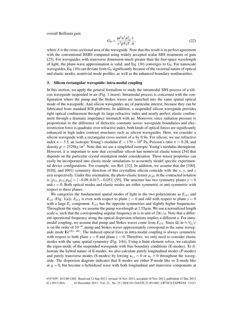
G0 =ω2n7 p2
12c3ρVLΓ
1A, (22)
where A is the cross-sectional area of the waveguide. Note that this result is in perfect agreementwith the conventional BSBS computed using widely accepted scalar SBS treatments of gain[25]. For waveguides with transverse dimension much greater than the free-space wavelengthof light, the plane-wave approximation is valid, and Eq. (10) converges to G0. For nanoscalewaveguides, Eq. (10) can deviate from G0 significantly because of the vectorial nature of opticaland elastic modes, nontrivial mode profiles, as well as the enhanced boundary nonlinearities.
3. Silicon rectangular waveguide: intra-modal coupling
In this section, we apply the general formalism to study the intramodal SBS process of a sili-con waveguide suspended in air (Fig. 1 insert). Intramodal process is concerned with the con-figuration where the pump and the Stokes waves are launched into the same spatial opticalmode of the waveguide. And silicon waveguides are of particular interest, because they can befabricated from standard SOI platforms. In addition, a suspended silicon waveguide providestight optical confinement through its large refractive index and nearly perfect elastic confine-ment through a dramatic impedance mismatch with air. Moreover, since radiation pressure isproportional to the difference of dielectric constants across waveguide boundaries and elec-trostriction force is quadratic over refractive index, both kinds of optical forces are significantlyenhanced in high index contrast structures such as silicon waveguides. Here, we consider asilicon waveguide with a rectangular cross-section of a by 0.9a. For silicon, we use refractiveindex n = 3.5, an isotropic Young’s modulus E = 170×109 Pa, Poisson’s ratio ν = 0.28, anddensity ρ = 2329kg/m3. Note that we use a simplified isotropic Young’s modulus throughout.However, it is important to note that crystalline silicon has nontrivial elastic tensor [54] thatdepends on the particular crystal orientation under consideration. These tensor properties caneasily be incorporated into elastic-mode simulations to accurately model specific experimen-tal device configurations. For example, see Ref. [32]. In addition, we assume that the [100],[010], and [001] symmetry direction of this crystalline silicon coincide with the x, y, and zaxis respectively. Under this orientation, the photo-elastic tensor pi jkl in the contracted notationis [p11, p12, p44] = [−0.09,0.017,−0.051] [55]. The structure has two symmetry planes y = 0and z = 0. Both optical modes and elastic modes are either symmetric or anti-symmetric withrespect to these planes.
We categorize the fundamental spatial modes of light in the two polarizations as Ey11 andEz11 (Fig. 1(a)). Ey11 is even with respect to plane z = 0 and odd with respect to plane y = 0with a large Ey component. Ez11 has the opposite symmetries and slightly higher frequencies.Throughout the study, we assume the pump wavelength at 1.55µm. We use a normalized lengthscale a, such that the corresponding angular frequency ω is in unit of 2πc/a. Note that a differ-ent operational frequency along the optical dispersion relations implies a different a. For intra-modal coupling, we assume that pump and Stokes waves come from Ey11. Since Ω/ω ≈ VL/cis on the order of 10−4, pump and Stokes waves approximately correspond to the same waveg-uide mode Eei(kx−ωt). The induced optical force in intra-modal coupling is always symmetricwith respect to both plane y = 0 and plane z = 0. Therefore, we only need to consider elasticmodes with the same spatial symmetry (Fig. 1(b)). Using a finite element solver, we calculatethe eigen-mode of the suspended waveguide with free boundary conditions (E-modes). To il-lustrate the hybrid nature of E-modes, we also calculate purely longitudinal modes (P-modes)and purely transverse modes (S-modes) by forcing uy,z = 0 or ux = 0 throughout the waveg-uide. The dispersion diagram indicates that E-modes are either P-mode like or S-mode likeat q = 0, but become a hybridized wave with both longitudinal and transverse components at
#197459 - $15.00 USD Received 12 Sep 2013; revised 18 Nov 2013; accepted 18 Nov 2013; published 12 Dec 2013(C) 2013 OSA 16 December 2013 | Vol. 21, No. 25 | DOI:10.1364/OE.21.031402 | OPTICS EXPRESS 31411
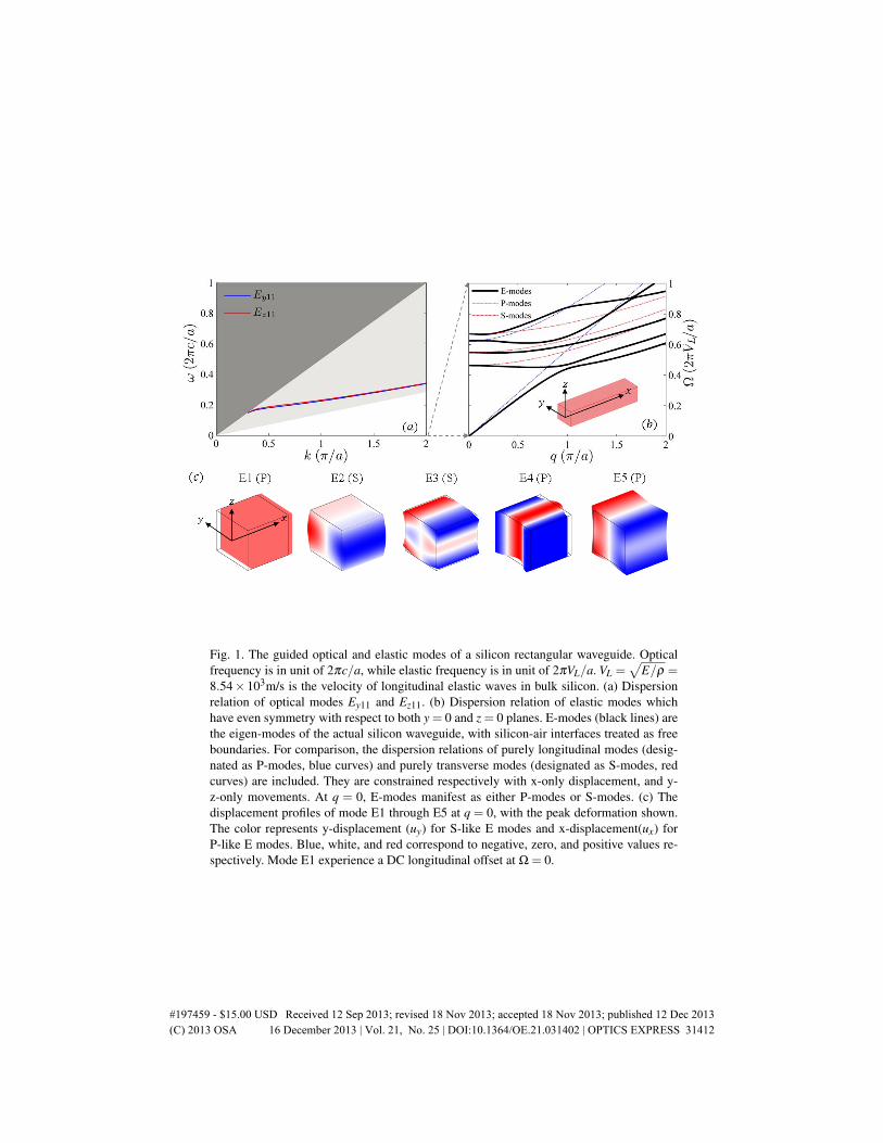
Fig. 1. The guided optical and elastic modes of a silicon rectangular waveguide. Opticalfrequency is in unit of 2πc/a, while elastic frequency is in unit of 2πVL/a. VL =
√E/ρ =
8.54× 10³m/s is the velocity of longitudinal elastic waves in bulk silicon. (a) Dispersionrelation of optical modes Ey11 and Ez11. (b) Dispersion relation of elastic modes whichhave even symmetry with respect to both y = 0 and z = 0 planes. E-modes (black lines) arethe eigen-modes of the actual silicon waveguide, with silicon-air interfaces treated as freeboundaries. For comparison, the dispersion relations of purely longitudinal modes (desig-nated as P-modes, blue curves) and purely transverse modes (designated as S-modes, redcurves) are included. They are constrained respectively with x-only displacement, and y-z-only movements. At q = 0, E-modes manifest as either P-modes or S-modes. (c) Thedisplacement profiles of mode E1 through E5 at q = 0, with the peak deformation shown.The color represents y-displacement (uy) for S-like E modes and x-displacement(ux) forP-like E modes. Blue, white, and red correspond to negative, zero, and positive values re-spectively. Mode E1 experience a DC longitudinal offset at Ω = 0.
#197459 - $15.00 USD Received 12 Sep 2013; revised 18 Nov 2013; accepted 18 Nov 2013; published 12 Dec 2013(C) 2013 OSA 16 December 2013 | Vol. 21, No. 25 | DOI:10.1364/OE.21.031402 | OPTICS EXPRESS 31412
q 6= 0. At q = 0, the mirror reflection symmetry with respect to plane x = 0 is conserved . Odd(even) modes with respect to x = 0 are purely longitudinal (transverse), separating E-modesinto P-modes and S-modes. At nonzero q, silicon-air boundaries hybridize the P-modes and theS-modes, resulting in E-modes with both longitudinal and transverse movement. Similar to theoptical mode, we can choose a proper phase so that ux is imaginary while uy,z are real.
3.1. Forward SBS
Spontaneous forward -Brillouin light scattering (i.e. or scattering from thermally populatedphonons) was first observed in optical fiber in 1985 [56, 57]. However, in conventional op-tical fibers forward stimulated Brillouin scattering (forward-SBS) processes are exceedinglyweak (typically orders of magnitude weaker than backward SBS). This is due to poor confine-ment (or delocalization) of the slow-group velocity phonon modes that mediate photon-phononcoupling in the forward scattering geometry [4, 27, 31]. However, waveguides with nanoscalefeature sizes can efficiently produce FSBS, for example, in photonic crystal fibers [4] and sus-pended silicon waveguides [31]. The frequency of the excitable elastic modes in FSBS is pinnedby the structure, independent of the incident optical frequency. Both structures provide strongtransverse phonon confinement, and such optical-phonon-like elastic modes are automaticallyphase-matched to higher orders of Stokes and anti-Stokes optical waves. The cascaded genera-tion of such elastic modes through an optical frequency can enable efficient phonon generationwith large quantum efficiency [4].
In FSBS, Ep = Es = E and q = 0. Equation (14) can be simplified toσxxσyyσzzσyzσxzσxy
=−12
ε0n4
p11 p12 p13p12 p22 p23p13 p23 p33
p44p55
p66
|Ex|2|Ey|2|Ez|2
2Re(EyE∗z )00
. (23)
Apparently, σxy = σxz = 0. From Eqs. (15) and (16), we conclude that f ESx = FES
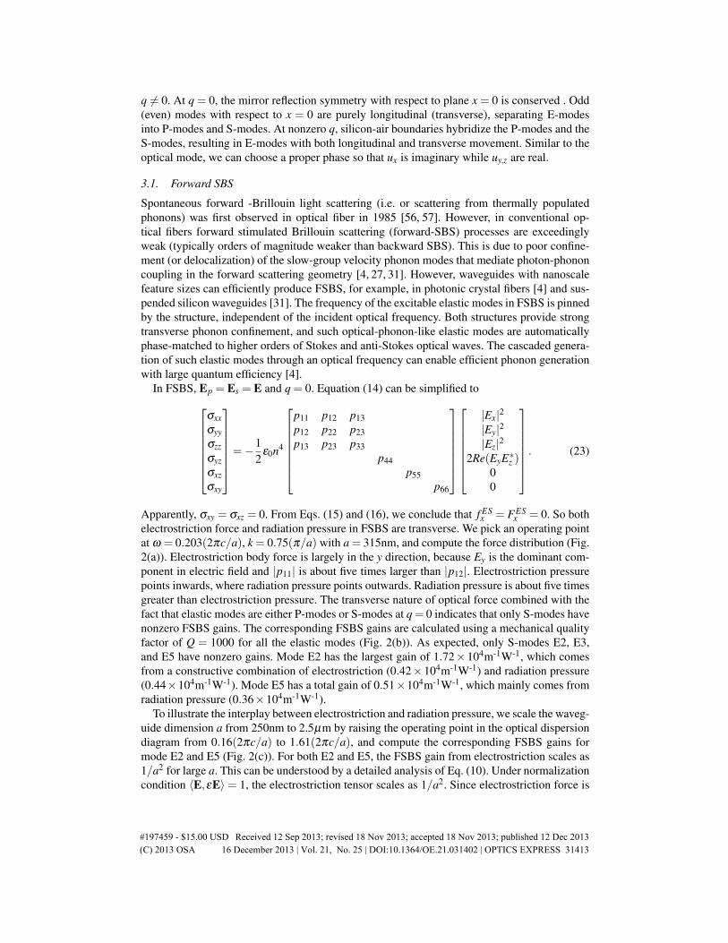
x = 0. So bothelectrostriction force and radiation pressure in FSBS are transverse. We pick an operating pointat ω = 0.203(2πc/a), k = 0.75(π/a) with a = 315nm, and compute the force distribution (Fig.2(a)). Electrostriction body force is largely in the y direction, because Ey is the dominant com-ponent in electric field and |p11| is about five times larger than |p12|. Electrostriction pressurepoints inwards, where radiation pressure points outwards. Radiation pressure is about five timesgreater than electrostriction pressure. The transverse nature of optical force combined with thefact that elastic modes are either P-modes or S-modes at q = 0 indicates that only S-modes havenonzero FSBS gains. The corresponding FSBS gains are calculated using a mechanical qualityfactor of Q = 1000 for all the elastic modes (Fig. 2(b)). As expected, only S-modes E2, E3,and E5 have nonzero gains. Mode E2 has the largest gain of 1.72× 10⁴m-1W-1, which comesfrom a constructive combination of electrostriction (0.42×10⁴m-1W-1) and radiation pressure(0.44×10⁴m-1W-1). Mode E5 has a total gain of 0.51×10⁴m-1W-1, which mainly comes fromradiation pressure (0.36×10⁴m-1W-1).
To illustrate the interplay between electrostriction and radiation pressure, we scale the waveg-uide dimension a from 250nm to 2.5µm by raising the operating point in the optical dispersiondiagram from 0.16(2πc/a) to 1.61(2πc/a), and compute the corresponding FSBS gains formode E2 and E5 (Fig. 2(c)). For both E2 and E5, the FSBS gain from electrostriction scales as1/a2 for large a. This can be understood by a detailed analysis of Eq. (10). Under normalizationcondition 〈E,εE〉 = 1, the electrostriction tensor scales as 1/a2. Since electrostriction force is
#197459 - $15.00 USD Received 12 Sep 2013; revised 18 Nov 2013; accepted 18 Nov 2013; published 12 Dec 2013(C) 2013 OSA 16 December 2013 | Vol. 21, No. 25 | DOI:10.1364/OE.21.031402 | OPTICS EXPRESS 31413
Fig. 2. Optical force distributions and the resultant gain coefficients of the Forward SBS. Inpanels (a) and (b), the width of the waveguide is a = 315nm, and the incident optical waveshave ω = 0.203(2πc/a), and k = 0.75(π/a). The elastic waves are generated at q = 0. (a)The force distribution of electrostriction body force density, electrostriction surface pres-sure, and radiation pressure respectively. All three types of optical forces are transverse. (b)Calculated FSBS gains of the elastic modes, assuming mechanical Q= 1000. Blue, red, andgreen bars represent FSBS gains under three conditions: electrostriction-only, radiation-pressure-only, and the combined effects. Only the S-like E modes have non-zero gains. (c)The scaling relation of FSBS gains as the device dimension a is varied from 0.25µm to2.5µm. Solid and dotted curves correspond to the gain coefficients for mode E2 and E5respectively.
#197459 - $15.00 USD Received 12 Sep 2013; revised 18 Nov 2013; accepted 18 Nov 2013; published 12 Dec 2013(C) 2013 OSA 16 December 2013 | Vol. 21, No. 25 | DOI:10.1364/OE.21.031402 | OPTICS EXPRESS 31414
essentially the divergence of electrostriction tensor, the total electrostriction force that apply tothe right half of the waveguide scales as 1/a3. Under normalization condition 〈um,ρum〉 = 1,um scales as 1/a. So the overlap integral scales as 1/a2. Under a fixed quality factor, the FSBSgain from electrostriction scales as 1/a2.
Unlike the electrostriction contributions that run parallel in different modes, the FSBS gainfrom radiation pressure scales as 1/a6 for mode E5 and 1/a8 for mode E2. This can also beunderstood from a breakdown of Eq. (10). Given the input power, the sum of average radiationpressure on the horizontal and vertical boundaries of the rectangular waveguide is proportionalto (ng−np)/A, where ng (np) is the group (phase) index, and A is the waveguide cross-section[47]. When the waveguide scales up, ng− np shrinks as 1/A. As a result, the sum of averageradiation pressure scales as 1/a4, and the FSBS gain from radiation pressure should scale as1/a6. For mode E2, however, radiation pressures on the horizontal and vertical boundariesgenerate overlap integrals with opposite signs. It is the difference rather than the sum betweenthe horizontal and vertical radiation pressures that determines the scaling of the FSBS gainsfrom radiation pressure. A closer examination reveals that although the overlap integral fromradiation pressure on the horizontal/vertical boundaries scales as 1/a4, the net overlap integralfrom radiation pressure scales as 1/a5, resulting in the 1/a8 scaling of FSBS gain from radiationpressure for mode E2.
3.2. Backward SBS
In traditional optical fibers, BSBS process is the qualitatively different from FSBS, as it is theonly configuration that allows strong photon-phonon coupling. Recent studies have demon-strated on-chip BSBS on chalcogenide rib waveguide [5]. Chip-based BSBS process has beenapplied in tunable slow light [58], tunable microwave photonic filter [59], and stimulated Bril-louin lasers [60].
In BSBS, Ep = E, Es = E∗, and q = 2k. Equation (14) can be simplified toσxxσyyσzzσyzσxzσxy
=−12
ε0n4
p11 p12 p13p12 p22 p23p13 p23 p33
p44p55
p66
E2
xE2
yE2
z2EyEz2ExEz2ExEy
. (24)
All components of σi j are nonzero, generating electrostriction force with both longitudinaland transverse components. We pick an operating point at ω = 0.203(2πc/a), k = 0.75(π/a)with a = 315nm, and compute the force distribution (Fig. 3(a)). Electrostriction body forcehas large longitudinal component over the waveguide cross-section, which mainly comes fromthe −iqσxx term in Eq. (15). The hybrid nature of optical forces combined with the fact thatall elastic modes are hybrid at nonzero q indicates that all elastic modes have nonzero BSBSgains. We compute the corresponding BSBS gains using a quality factor Q = 1000 for all theelastic modes (Fig. 3(b)). For mode E1 and E2, electrostriction force and radiation pressure addup destructively, resulting in small BSBS gains of 0.089×10⁴m-1W-1 and 0.086×10⁴m-1W-1
respectively.Next, we vary a from 250nm to 2.5µm and compute the corresponding BSBS gains for mode
E1 (Fig. 3(c)). For comparison, we also compute the conventional BSBS gain G0. The BSBSgain from electrostriction of mode E1 decays very quickly. In contrast, G0 scales as 1/a2 asrequired by Eq. (22). The reason is that, although mode E1 starts as a longitudinal plane wavefor q ≈ 0, it quickly evolves into surface-vibrating wave as q increases. There are two waysto recover the scaling of G0. First, we can force purely longitudinal movement by consider-
#197459 - $15.00 USD Received 12 Sep 2013; revised 18 Nov 2013; accepted 18 Nov 2013; published 12 Dec 2013(C) 2013 OSA 16 December 2013 | Vol. 21, No. 25 | DOI:10.1364/OE.21.031402 | OPTICS EXPRESS 31415
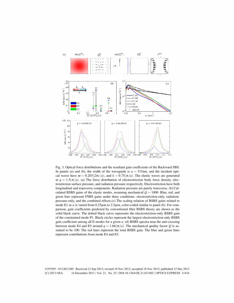
Fig. 3. Optical force distributions and the resultant gain coefficients of the Backward SBS.In panels (a) and (b), the width of the waveguide is a = 315nm, and the incident opti-cal waves have ω = 0.203(2πc/a), and k = 0.75(π/a). The elastic waves are generatedat q = 1.5(π/a). (a) The force distribution of electrostriction body force density, elec-trostriction surface pressure, and radiation pressure respectively. Electrostriction have bothlongitudinal and transverse components. Radiation pressure are purely transverse. (b) Cal-culated BSBS gains of the elastic modes, assuming mechanical Q = 1000. Blue, red, andgreen bars represent FSBS gains under three conditions: electrostriction-only, radiation-pressure-only, and the combined effects.(c) The scaling relation of BSBS gains related tomode E1 as a is varied from 0.25µm to 2.5µm, color-coded similar to panel (b). For com-parison, gain coefficients predicted by conventional fiber BSBS theory are shown as thesolid black curve. The dotted black curve represents the electrostriction-only BSBS gainof the constrained mode P1. Black circles represent the largest electrostriction-only BSBSgain coefficient among all E-modes for a given a. (d) BSBS spectra near the anti-crossingbetween mode E4 and E5 around q = 1.66(π/a). The mechanical quality factor Q is as-sumed to be 100. The red lines represent the total BSBS gain. The blue and green linesrepresent contributions from mode E4 and E5.
#197459 - $15.00 USD Received 12 Sep 2013; revised 18 Nov 2013; accepted 18 Nov 2013; published 12 Dec 2013(C) 2013 OSA 16 December 2013 | Vol. 21, No. 25 | DOI:10.1364/OE.21.031402 | OPTICS EXPRESS 31416
ing P-modes in Fig. 1(b). Mode P1, the fundamental P-mode, is exactly the longitudinal planewave, characterized by uniform longitudinal vibrations across the waveguide cross-section andan approximately linear dispersion relation. The BSBS from electrostriction for mode P1 doesconverge to G0 (Fig. 3(c)). Second, the dispersion curve of mode P1 intersects with the dis-persion curves of many E-modes as q increases. For a given q, the E-modes which are closeto the intersection point become P1-like with approximately uniform longitudinal vibrationsacross the waveguide cross-section. The BSBS gain of these E-modes should be much largerthan other E-modes, and close to the gain of mode P1. To verify this point, we compute theBSBS gains of a large number of E-modes. The maximal gain from electrostriction among allthe E-modes does converge to G0 as a exceeds several microns (Fig. 3(c)).
In BSBS, the operating point in the elastic dispersion diagram can be tuned by varying theoperating point in the optical dispersion diagram through phase-matching condition q = 2k.One unique feature about the elastic dispersion diagram is the abundance of anti-cross betweenthe hybridized elastic modes. The two elastic modes involved in an anti-crossing point typi-cally have disparate spatial distributions and quite different BSBS gains. These two modes willexchange their spatial distributions and corresponding BSBS gains when q is scanned throughthe anti-cross region, as demonstrated in Fig. 3(d). Figure 3(d) also show that the total gainspectrum can have complex shapes. The frequency response method in [31] can only calculatethe aggregated gain. The eigen-mode method developed here can not only separate the contri-butions from different elastic modes, but also parameterize the gain of individual modes withsimple physical quantities.
4. Silicon rectangular waveguide: inter-modal coupling
In this section, we explore inter-modal coupling of the same silicon rectangular waveguide[30]. In inter-modal SBS, pump and Stokes waves can have distinct spatial distributions, whichessentially double the degree of freedoms of tailoring optical force distributions. In addition,pump and Stokes waves can have different or even orthogonal polarizations so that the twowaves can be easily separated with a polarizing beam splitter. For the rectangular waveguidediscussed above, the optical force in intra-modal coupling is always symmetric with respect toy = 0 and z = 0, exciting elastic modes with the matching symmetry. In inter-modal coupling,however, optical forces with all possible symmetries can be generated, and elastic modes withall possible symmetries can be excited. For instance, we consider the coupling between Ey11(pump) and Ez11 (Stokes). The operating point is ω = 0.203(2πc/a), kp = 0.750(π/a), ks =0.665(π/a), and q = 0.085(π/a) with a = 315nm. Because Ey11 and Ez11 have the oppositesymmetries with respect to both y = 0 and z = 0, the induced optical force is anti-symmetricwith respect to both planes (Fig. 4(a)). Both electrostriction body force and radiation pressuretry to pull the waveguide in one diagonal and squeeze the waveguide in the other diagonal.Electrostriction pressure has the opposite effect, but is much weaker than the radiation pressure.
Under such optical force, elastic modes which are odd with respect to both y = 0 and z = 0(O-modes) are excited. We calculate the SBS gains of mode O1 through O5 using a mechanicalquality factor Q = 1000 for all the modes (Fig. 4(b)). Mode O1 represents a rotation aroundx axis. The overlap integral is proportional to the torque. The y component and z componentof the optical forces generate torques with opposite signs, which significantly reduces the totaloverlap integral. Mode O1 still has a sizable SBS gains because of its small elastic frequencyΩ = 0.024(2πVL/a). Mode O2 represents a breathing motion along the diagonal. Its modalprofile coincides quite well with the optical force distribution. The constructive combinationbetween electrostriction force and radiation pressure results in large gain of 1.54×10⁴m-1W-1.Mode O3 only have small SBS gains since it is dominantly longitudinal while the optical forcesare largely transverse. The SBS gains of O4, O5 and higher order modes are close to zero
#197459 - $15.00 USD Received 12 Sep 2013; revised 18 Nov 2013; accepted 18 Nov 2013; published 12 Dec 2013(C) 2013 OSA 16 December 2013 | Vol. 21, No. 25 | DOI:10.1364/OE.21.031402 | OPTICS EXPRESS 31417
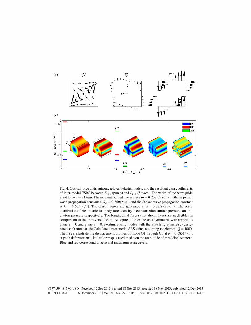
Fig. 4. Optical force distributions, relavant elastic modes, and the resultant gain coefficientsof inter-modal FSBS between Ey11 (pump) and Ez11 (Stokes). The width of the waveguideis set to be a= 315nm. The incident optical waves have ω = 0.203(2πc/a), with the pump-wave propagation constant at kp = 0.750(π/a), and the Stokes-wave propagation constantat ks = 0.665(π/a). The elastic waves are generated at q = 0.085(π/a). (a) The forcedistribution of electrostriction body force density, electrostriction surface pressure, and ra-diation pressure respectively. The longitudinal forces (not shown here) are negligible, incomparison to the transverse forces. All optical forces are anti-symmetric with respect toplane y = 0 and plane z = 0, exciting elastic modes with the matching symmetry (desig-nated as O-modes). (b) Calculated inter-modal SBS gains, assuming mechanical Q = 1000.The insets illustrate the displacement profiles of mode O1 through O5 at q = 0.085(π/a),at peak deformation. ”Jet” color map is used to shown the amplitude of total displacement.Blue and red correspond to zero and maximum respectively.
#197459 - $15.00 USD Received 12 Sep 2013; revised 18 Nov 2013; accepted 18 Nov 2013; published 12 Dec 2013(C) 2013 OSA 16 December 2013 | Vol. 21, No. 25 | DOI:10.1364/OE.21.031402 | OPTICS EXPRESS 31418
mainly because the complicated mode profiles is spatially mismatched with the optical forcedistribution: the rapid spatial oscillation of the elastic modes cancels out the overlap integralsto a large extent.
5. Concluding remarks
In this article, we present a general framework of calculating the SBS gain via the overlap inte-gral between optical forces and elastic eigen-modes. Our method improved upon the frequencyresponse representation of SBS gains [31]. By decomposing the frequency response into elasticeigen-modes, we show that the SBS gain is the sum of many Lorentzian components which cen-ter at elastic eigen-frequencies. The SBS gain spectrum is completely determined by the qual-ity factor and maximal gain of individual elastic modes. Therefore, our method is conceptuallyclearer and computationally more efficient than the frequency response method. Through thestudy of a silicon waveguide, we demonstrate that our method can be applied to both FSBS andBSBS, both intra-modal and inter-modal coupling, both nanoscale and microscale waveguides.Both analytical expressions and numerical examples show that SBS nonlinearity is tightly con-nected to the symmetry, polarization, and spatial distributions of optical and elastic modes. Theoverlap integral formula of SBS gains provides the guidelines of tailoring and optimizing SBSnonlinearity through material selection and structural design.
Acknowledgments
The authors acknowledge support from the MesoDynamic Architectures program at theDARPA under the direction of Dr Jeffrey L. Rogers. Z.W acknowledges support from theAlfred. P. Sloan Research Fellowship. We are grateful to Whitney Purvis Rakich for carefulreading and critique of this manuscript.
#197459 - $15.00 USD Received 12 Sep 2013; revised 18 Nov 2013; accepted 18 Nov 2013; published 12 Dec 2013(C) 2013 OSA 16 December 2013 | Vol. 21, No. 25 | DOI:10.1364/OE.21.031402 | OPTICS EXPRESS 31419