nasa aeronautics research institute active truss for fast
TRANSCRIPT
NASA Aeronautics Research Institute
Active Truss for Fast Response Tip Clearance Modulation
NASA Aeronautics Research Mission Directorate (ARMD) FY12 LEARN Phase I Technical Seminar
Nov 13-15, 2013
Fanping Sun, Zaffir Chaudhry, Hailing Wu,
Lee Hoffman and Huan Zhang
United Technologies Research Center
NASA Aeronautics Research Institute
Outlines
•The innovation •Technical approach •Impact of the innovation •LEARN Phase I Results •Summary •Next steps
Nov 13–15, 2013 NASA Aeronautics Research Mission Directorate FY12 LEARN Phase I Technical Seminar 2
NASA Aeronautics Research Institute
Need for Innovation
Nov 13–15, 2013 NASA Aeronautics Research Mission Directorate FY12 LEARN Phase I Technical Seminar 3
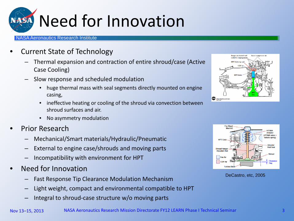
• Current State of Technology – Thermal expansion and contraction of entire shroud/case (Active
Case Cooling) – Slow response and scheduled modulation
• huge thermal mass with seal segments directly mounted on engine casing,
• ineffective heating or cooling of the shroud via convection between shroud surfaces and air.
• No asymmetry modulation
• Prior Research – Mechanical/Smart materials/Hydraulic/Pneumatic – External to engine case/shrouds and moving parts – Incompatibility with environment for HPT
• Need for Innovation – Fast Response Tip Clearance Modulation Mechanism – Light weight, compact and environmental compatible to HPT – Integral to shroud-case structure w/o moving parts
DeCastro, etc, 2005

NASA Aeronautics Research Institute
Impact of Innovation
A Fast Response Tip Clearance Modulation •Enable turbine tip clearance set to “optimal” during longest flight segment (cruise) •Reduce specific fuel burn (SFC) and exhaust gas temperature (EGT)
•0.01” in turbine blade tip clearance equals: –1 % in SFC –10° C in EGT
•Low CO2 emission •More time on wing
Nov 13–15, 2013 NASA Aeronautics Research Mission Directorate FY12 LEARN Phase I Technical Seminar 4

NASA Aeronautics Research Institute
Innovation-Active Truss Modulation
Nov 13–15, 2013 NASA Aeronautics Research Mission Directorate FY12 LEARN Phase I Technical Seminar 5
Approach: • Variable geometry active truss for tip clearance modulation • Truss actuation by thermally induced strains • Low thermal mass and large surface area for heat exchange Benefits: • Sustain beauties of thermal expansion approach • Fast Response-one order of magnitude improvement • Light weight and Integral to shroud-case structure • Asymmetric and symmetry clearance modulation

NASA Aeronautics Research Institute
Active Truss Modulation (ATM)
Nov 13–15, 2013 NASA Aeronautics Research Mission Directorate FY12 LEARN Phase I Technical Seminar 6
Engine Case Truss Actuators Tip Clearance
Interlock Tabs
Segmented Shrouds
Cooling Air Pressure Differential
Electric Connection

NASA Aeronautics Research Institute
Nov 13–15, 2013 NASA Aeronautics Research Mission Directorate FY12 LEARN Phase I Technical Seminar 7
Dual Tetrahedron Dual Pyramid
Parallel Theta Ring (2D)
Prime Movers
Core Elements of Truss Actuation
•Actuation by linear thermal expansion •Structural amplification of displacement •Multiple inputs and single output actuation •Low thermal mass and volume density (<0.1) •One order of magnitude faster response than engine case cooling (ACC)

NASA Aeronautics Research Institute
Principle of Truss Actuation
ω22
2 cos123
2 −=−= db
d lllH
For thermally induced actuation •Displacement •Stiffness •Response •Temperature
D
α
∆H
ω
F
H
)(cos1
)cos(3
32
3/32
222 ω
ω
−
−=
−
−=
∂∂
bd
b
b ll
l
lH
)(cos12
3/2
222 ω−=
−=
∂∂
bd
d
d lll
lH
ib
iib
jd
jj
dt dl
lHdl
lHH ∑∑
== ∂∂
−∂∂
=∆9~76~1
Thermal expansion in each members
dlteddj
d ΔTCldl =
bltebbi
b ΔTCldl =
Actuation displacement
Tip clearance modulation
Nov 13–15, 2013 NASA Aeronautics Research Mission Directorate FY12 LEARN Phase I Technical Seminar

NASA Aeronautics Research Institute
Principle of Truss Actuation
Member buckling (L/r slenderness)
Nov 13–15, 2013 NASA Aeronautics Research Mission Directorate FY12 LEARN Phase I Technical Seminar
bd
bdD kk
kkK
6cos4sin92
2
+=
ωω
Structural stiffness
2
2
)/(4
dLE
bcr
πσ =
22
)/()tan(
)cos/323(bld
ωωπρ +=
Volume density (weight)
Dt K
FHH +∆=∆
Total displacement modulation
D
α
∆H
ω
F
H

NASA Aeronautics Research Institute
10
A
E
B
C
D
α
∆H
ω
F
H
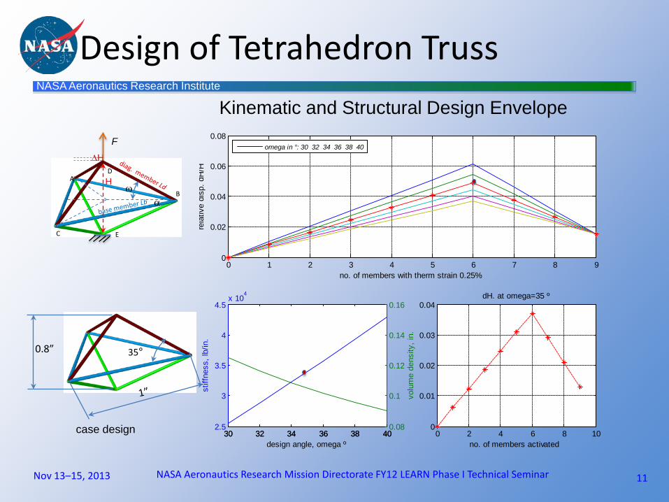
Kinematic and Structural Design Envelope
Nov 13–15, 2013 NASA Aeronautics Research Mission Directorate FY12 LEARN Phase I Technical Seminar
Design of Tetrahedron Truss
25 30 35 40 452
2.5
3
3.5
4
4.5
5
ampl
ifica
tion
design angle, omega º
25 30 35 40 451
2
3
4
5
6x 10
4
stiff
ness
, lb/
in.
design angle, omega º
dH/dLddH/dLb
25 30 35 40 450.4
0.6
0.8
1
1.2
1.4
heig
ht, i
n.
NASA Aeronautics Research Institute
Design of Tetrahedron Truss
11
A
E
B
C
D
α
∆H
ω
F
H
Nov 13–15, 2013 NASA Aeronautics Research Mission Directorate FY12 LEARN Phase I Technical Seminar
35° 0.8”
case design
0 1 2 3 4 5 6 7 8 90
0.02
0.04
0.06
0.08
rela
tive
disp
. dH
/H
no. of members with therm strain 0.25%
30 32 34 36 38 402.5
3
3.5
4
4.5x 10
4
stiff
ness
, lb/
in.
design angle, omega º0 2 4 6 8 10
0
0.01
0.02
0.03
0.04dH. at omega=35 º
no. of members activated
omega in °: 30 32 34 36 38 40
30 32 34 36 38 400.08
0.1
0.12
0.14
0.16
volu
me
dens
ity, i
n.
Kinematic and Structural Design Envelope

NASA Aeronautics Research Institute
∆ T=300 °F applied to 1 diag. member Thermal expansion field
FEM Model
Nov 13–15, 2013 NASA Aeronautics Research Mission Directorate FY12 LEARN Phase I Technical Seminar
Design of Tetrahedron Truss
∆ T=300 °F applied to 3 diag. members Thermal expansion field
NASA Aeronautics Research Institute
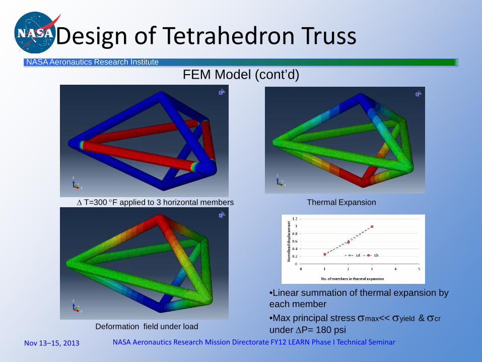
FEM Model (cont’d)
Nov 13–15, 2013 NASA Aeronautics Research Mission Directorate FY12 LEARN Phase I Technical Seminar
Thermal Expansion
•Linear summation of thermal expansion by each member •Max principal stress σmax<< σyield & σcr under ∆P= 180 psi
Design of Tetrahedron Truss
∆ T=300 °F applied to 3 horizontal members
Deformation field under load

NASA Aeronautics Research Institute
Electric Activation of Truss Matrix
14
Direct resistive heating topologies •Heating each member individually •Group collective heating (base and diagonal) •Combination of series and parallel heating •Intelligent heating-Wheatstone bridge effect Challenge: Large current and low voltage
V+ V-
I=0
Nov 13–15, 2013 NASA Aeronautics Research Mission Directorate FY12 LEARN Phase I Technical Seminar
•Cell to cell series connection •Full actuation •Fail safe •Embedded wiring in case

NASA Aeronautics Research Institute
V+
V-
V+
V-
Series connection and partial grouping (2/3 activation)
Parallel/series connection and partial grouping (1/2 activation)
Nov 13–15, 2013 NASA Aeronautics Research Mission Directorate FY12 LEARN Phase I Technical Seminar
Electric Activation of Truss Matrix

NASA Aeronautics Research Institute
16
Air Cooling Modeling • Steady state heating/cooling • Transient cooling
inlet
outlet periodic
Top wall
Bottom wall
truss
Air Cooling- Activation and Deactivation
Remain activated, electric power on
Deactivated, electric power off
Nov 13–15, 2013 NASA Aeronautics Research Mission Directorate FY12 LEARN Phase I Technical Seminar

NASA Aeronautics Research Institute
17
•Six members being electrically heated at 899 ºC (1650°F) while being air cooled •Three members being air cooled to 732ºC (1350°F)
To maintain temperature difference while electrically heated
Member temperature contours
Air flow (m/s) 0.1 0.1 10
Temperature difference between heated and unheated wires (°C)
100 110 180
Heat dissipation rate (W) 7.04 6.9 42.2
Air Cooling- Activation Mode
Nov 13–15, 2013 NASA Aeronautics Research Mission Directorate FY12 LEARN Phase I Technical Seminar
NASA Aeronautics Research Institute
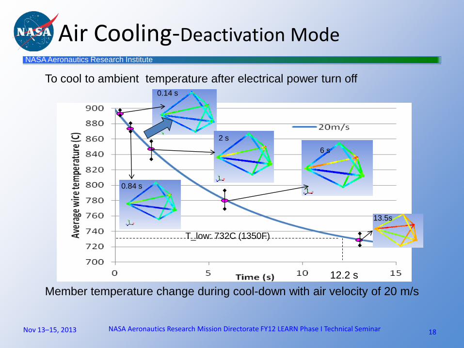
18
Member temperature change during cool-down with air velocity of 20 m/s
T_low: 732C (1350F)
12.2 s
0.14 s
2 s
0.84 s
6 s
13.5s
Air Cooling-Deactivation Mode
To cool to ambient temperature after electrical power turn off
Nov 13–15, 2013 NASA Aeronautics Research Mission Directorate FY12 LEARN Phase I Technical Seminar
NASA Aeronautics Research Institute
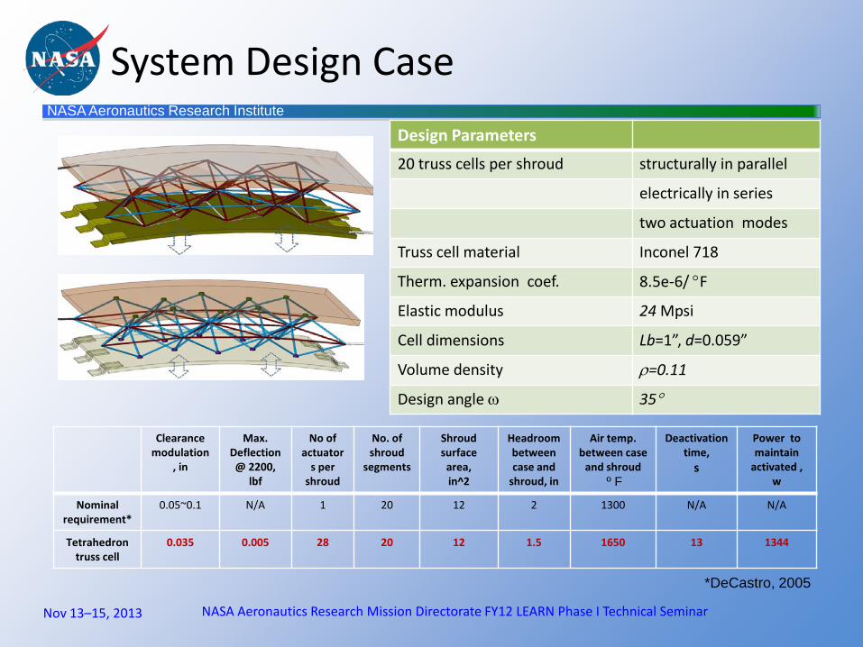
System Design Case
Clearance modulation
, in
Max. Deflection @ 2200,
lbf
No of actuator
s per shroud
No. of shroud
segments
Shroud surface
area, in^2
Headroom between case and
shroud, in
Air temp. between case
and shroud º F
Deactivation time,
s
Power to maintain
activated , w
Nominal requirement*
0.05~0.1 N/A 1 20 12 2 1300 N/A N/A
Tetrahedron truss cell
0.035 0.005 28 20
12
1.5 1650
13 1344
*DeCastro, 2005
Nov 13–15, 2013 NASA Aeronautics Research Mission Directorate FY12 LEARN Phase I Technical Seminar
Design Parameters 20 truss cells per shroud structurally in parallel
electrically in series
two actuation modes
Truss cell material Inconel 718
Therm. expansion coef. 8.5e-6/ °F
Elastic modulus 24 Mpsi
Cell dimensions Lb=1”, d=0.059”
Volume density ρ=0.11
Design angle ω 35°
NASA Aeronautics Research Institute
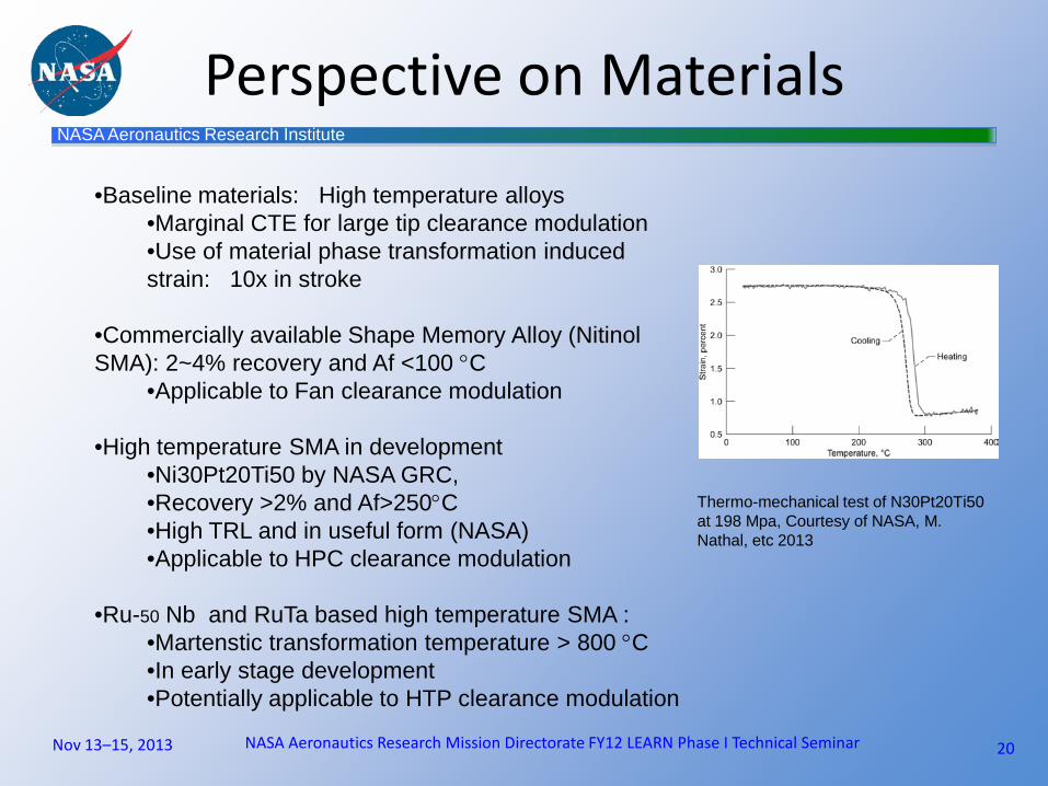
Perspective on Materials
20
Thermo-mechanical test of N30Pt20Ti50 at 198 Mpa, Courtesy of NASA, M. Nathal, etc 2013
•Baseline materials: High temperature alloys •Marginal CTE for large tip clearance modulation •Use of material phase transformation induced strain: 10x in stroke
•Commercially available Shape Memory Alloy (Nitinol SMA): 2~4% recovery and Af <100 °C
•Applicable to Fan clearance modulation
•High temperature SMA in development •Ni30Pt20Ti50 by NASA GRC, •Recovery >2% and Af>250°C •High TRL and in useful form (NASA) •Applicable to HPC clearance modulation
•Ru-50 Nb and RuTa based high temperature SMA :
•Martenstic transformation temperature > 800 °C •In early stage development •Potentially applicable to HTP clearance modulation
Nov 13–15, 2013 NASA Aeronautics Research Mission Directorate FY12 LEARN Phase I Technical Seminar

NASA Aeronautics Research Institute
Nov 13–15, 2013 NASA Aeronautics Research Mission Directorate FY12 LEARN Phase I Technical Seminar
Proof of Concept Experiment In progress
Qualitatively Evaluation of •Displacement output
•Linear and binary thermal expansion •Response time in cooling •Structural stiffness
Nitinol Tetrahedron Actuator •Thermal expansion : 6.1e-6 /°F •Electrical resistivity : 39 mΩ-in
Anticipated results
Test apparatus
NASA Aeronautics Research Institute
Summary
22
•Active truss tip clearance modulation by thermal expansion is conceptually viable
•kinematically, structurally and thermally •Fast response is analytically verified to be within tens of seconds at HPT environment •Modulation by material linear thermal expansion is adequate for small and mi-size engines •Experimental validation of tetrahedron truss actuation in progress
•Challenges identified in materials •High induced strain for large transport engine •High temperature to enable HPT •High resistivity to ease direct electric heating
Nov 13–15, 2013 NASA Aeronautics Research Mission Directorate FY12 LEARN Phase I Technical Seminar

NASA Aeronautics Research Institute
Next Steps
NASA Aeronautics Research Mission Directorate FY12 LEARN Phase I Technical Seminar 23
•LEARN Phase I •Enhance modeling fidelity of single cell-truss actuation
•Structural FEM model close loop with air cooling models •Air cooling models close loop with electric heating
•Experimental validation of Tetrahedron Actuation in room temperature. •LEARN Phase II •Expanding structural and air cooling models to large scale repetitive Active Truss Matrix structure •Notional design and analysis of tip modulation on a notional engine •Electric heating and control of truss modulation •High temperature shape memory alloy (HTSMA)
Nov 13–15, 2013

NASA Aeronautics Research Institute
Distribution/Dissemination
NASA Aeronautics Research Mission Directorate FY12 LEARN Phase I Technical Seminar 24
In 2012, NARI awarded ARMD LEARN Fund grants to make deliberate investments in early-stage and potentially revolutionary aviation concepts and technologies that are aligned with NASA's mission. These grants went to teams external to NASA. The objectives of this three-day seminar are to increase awareness of LEARN activities within NASA projects, to provide technical feedback to LEARN principal investigators, and educate/inform the public. This will help facilitate transfer of LEARN-developed technologies within NASA and disseminate LEARN findings to the external aeronautics community, including academia, industry, and the general public.
Distribution and dissemination are unlimited
Nov 13–15, 2013