n5126v familiarization - connecticut flight …...n5126v familiarization rev - 12/01/2019 david...
TRANSCRIPT
N5126V Familiarization
Rev - 12/01/2019 David Chapdelaine Page 1
This document is to highlight some of the aircraft systems in N5126V. All pilots must be intimate with the POH and weight and balance for the Cutlass 172RG.
Usable Fuel:
o Full tanks: 2x 33 gal ...................... 66 gal
o Usable Fuel .................................. 62 gal
Oil Capacity ........................................ 5 -9 qt
Tire Pressure ....................... POH page 8-14
o Nose ................................... 40 - 50 lbs
o Main .................................. 60 - 68 lbs
VR Rotate 55 KIAS
VX Best Climb Rate 67 KIAS POH = pg 4-3
Chk List
VY Best Rate of Climb 84 KIAS POH = pg 4-3
Chk List
VA Maneuvering Speed
2,650 lb = 105 KIAS
POH = 2-5 & 4-3 Chk List
2,250 lb = 96 KIAS POH = 2-5 & 4-3
1,850 lb = 87 KIAS POH = 2-5 & 4-3
Chk List
VFE Max Flap Extend Speed 10° = 130 KIAS
POH = 2-5 Chk List
>10° = 100 KIAS POH = 2-5
Chk List
VSO Stall Speed Dirty 42 KIAS Chk List
VS1 Stall Speed Clean 50 KIAS Chk List
VNO Max Structural Speed 145 KIAS Chk List
VNE Never Exceed 164 KIAS POH = 2-5
Chk List
VLO Max Landing Gear Operating
140 KIAS POH = 2-5
VLE Max Landing Gear Extend
164 KIAS POH = 2-5
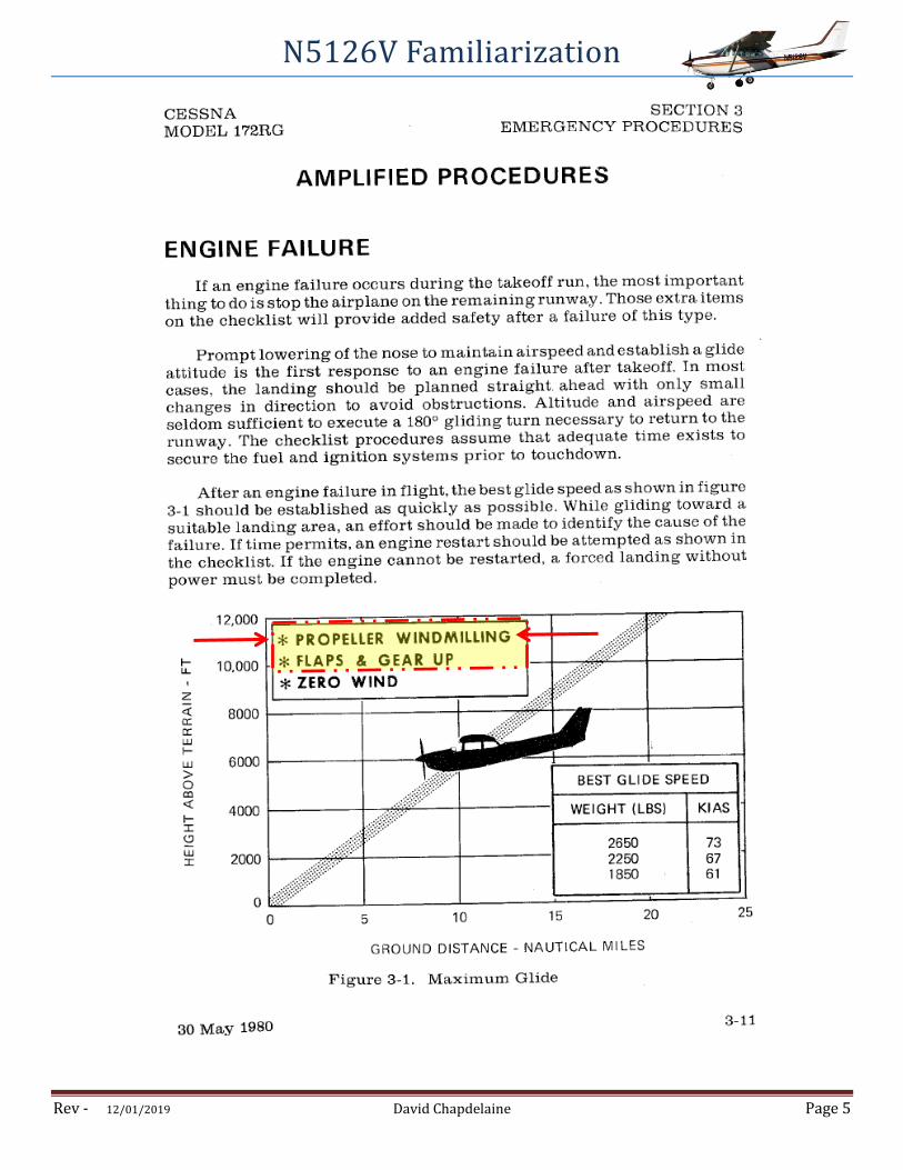
VG Best Glide - Clean
2,650 lb = 73 KIAS POH = 3-3 & 3-
11 Chk List
2,250 lb = 67 KIAS POH = 3-3 & 3-
11
1,850 lb = 61 KIAS POH = 3-3 & 3-
11
Cross Wind 15 KIAS POH = 4-3
Climb
Normal Climb out 70KIAS - 80KIAS POH = 4-3
Enroute (Best Rate) 85KIAS - 90KIAS POH = 4-3 & 4-9
Enroute (Best Angle) 67KIAS POH pg 4-3
Approach
Final w/ flaps up 65KIAS - 75KIAS
Final w/ flaps down 60KIAS - 70KIAS
N5126V Familiarization
Rev - 12/01/2019 David Chapdelaine Page 2
Landing Gear
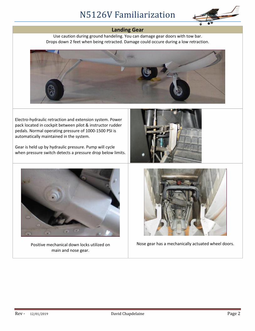
Use caution during ground handeling. You can damage gear doors with tow bar. Drops down 2 feet when being retracted. Damage could occure during a low retraction.
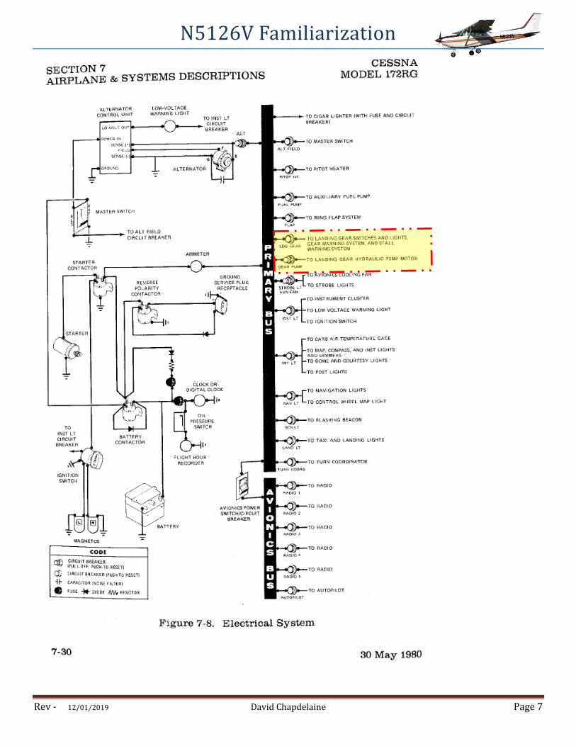
Electro-hydraulic retraction and extension system. Power pack located in cockpit between pilot & instructor rudder pedals. Normal operating pressure of 1000-1500 PSI is automatically maintained in the system.
Gear is held up by hydraulic pressure. Pump will cycle when pressure switch detects a pressure drop below limits.
Positive mechanical down locks utilized on main and nose gear.
Nose gear has a mechanically actuated wheel doors.
N5126V Familiarization
Rev - 12/01/2019 David Chapdelaine Page 3
Landing Gear
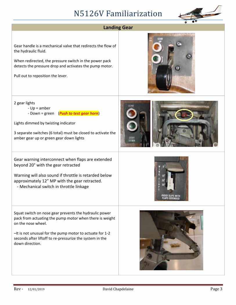
Gear handle is a mechanical valve that redirects the flow of the hydraulic fluid.
When redirected, the pressure switch in the power pack detects the pressure drop and activates the pump motor.
Pull out to reposition the lever.
2 gear lights - Up = amber - Down = green (Push to test gear horn)
Lights dimmed by twisting indicator
3 separate switches (6 total) must be closed to activate the amber gear up or green gear down lights
Gear warning interconnect when flaps are extended beyond 20° with the gear retracted
Warning will also sound if throttle is retarded below approximately 12” MP with the gear retracted. - Mechanical switch in throttle linkage
Squat switch on nose gear prevents the hydraulic power pack from actuating the pump motor when there is weight on the nose wheel.
–It is not unusual for the pump motor to actuate for 1-2 seconds after liftoff to re-pressurize the system in the down direction.
N5126V Familiarization
Rev - 12/01/2019 David Chapdelaine Page 4
Landing Gear
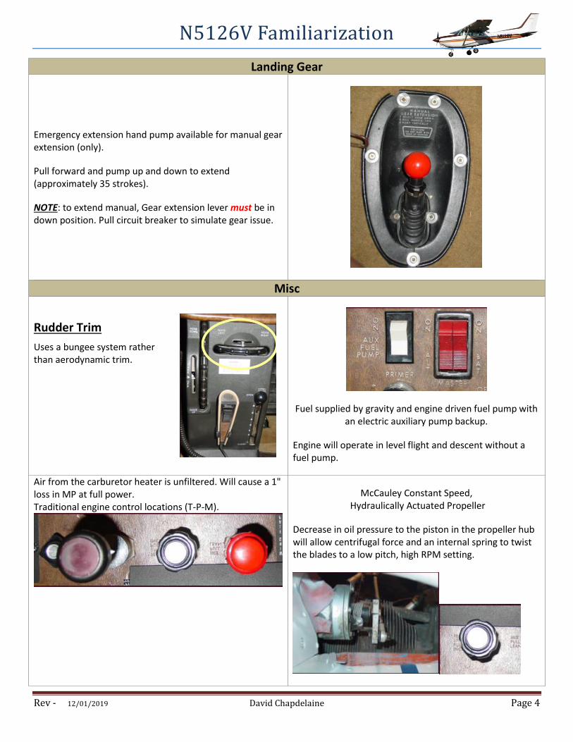
Emergency extension hand pump available for manual gear extension (only).
Pull forward and pump up and down to extend (approximately 35 strokes).
NOTE: to extend manual, Gear extension lever must be in down position. Pull circuit breaker to simulate gear issue.
Misc
Rudder Trim
Uses a bungee system rather than aerodynamic trim.
Fuel supplied by gravity and engine driven fuel pump with an electric auxiliary pump backup.
Engine will operate in level flight and descent without a fuel pump.
Air from the carburetor heater is unfiltered. Will cause a 1" loss in MP at full power. Traditional engine control locations (T-P-M).
McCauley Constant Speed, Hydraulically Actuated Propeller
Decrease in oil pressure to the piston in the propeller hub will allow centrifugal force and an internal spring to twist the blades to a low pitch, high RPM setting.
N5126V Familiarization
Rev - 12/01/2019 David Chapdelaine Page 5

N5126V Familiarization
Rev - 12/01/2019 David Chapdelaine Page 6
N5126V Familiarization
Rev - 12/01/2019 David Chapdelaine Page 7
N5126V Familiarization
Rev - 12/01/2019 David Chapdelaine Page 8
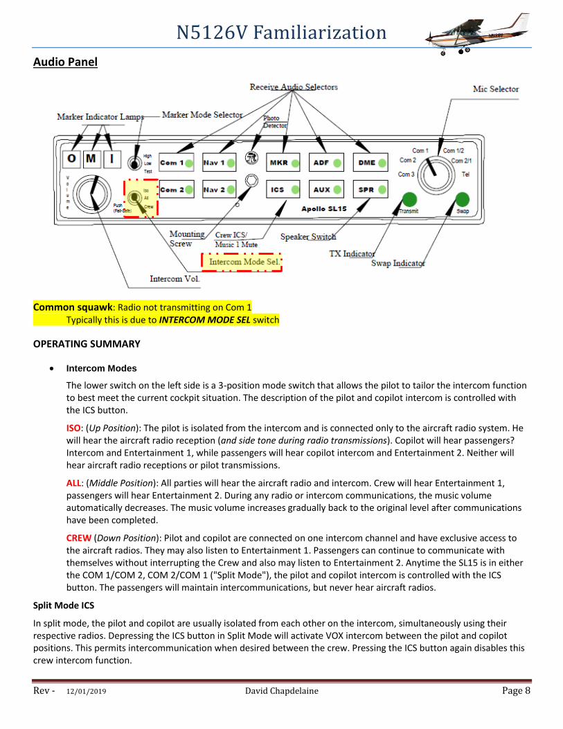
Audio Panel
Common squawk: Radio not transmitting on Com 1 Typically this is due to INTERCOM MODE SEL switch
OPERATING SUMMARY
Intercom Modes
The lower switch on the left side is a 3-position mode switch that allows the pilot to tailor the intercom function to best meet the current cockpit situation. The description of the pilot and copilot intercom is controlled with the ICS button.
ISO: (Up Position): The pilot is isolated from the intercom and is connected only to the aircraft radio system. He will hear the aircraft radio reception (and side tone during radio transmissions). Copilot will hear passengers? Intercom and Entertainment 1, while passengers will hear copilot intercom and Entertainment 2. Neither will hear aircraft radio receptions or pilot transmissions.
ALL: (Middle Position): All parties will hear the aircraft radio and intercom. Crew will hear Entertainment 1, passengers will hear Entertainment 2. During any radio or intercom communications, the music volume automatically decreases. The music volume increases gradually back to the original level after communications have been completed.
CREW (Down Position): Pilot and copilot are connected on one intercom channel and have exclusive access to the aircraft radios. They may also listen to Entertainment 1. Passengers can continue to communicate with themselves without interrupting the Crew and also may listen to Entertainment 2. Anytime the SL15 is in either the COM 1/COM 2, COM 2/COM 1 ("Split Mode"), the pilot and copilot intercom is controlled with the ICS button. The passengers will maintain intercommunications, but never hear aircraft radios.
Split Mode ICS
In split mode, the pilot and copilot are usually isolated from each other on the intercom, simultaneously using their respective radios. Depressing the ICS button in Split Mode will activate VOX intercom between the pilot and copilot positions. This permits intercommunication when desired between the crew. Pressing the ICS button again disables this crew intercom function.

N5126V Familiarization
Rev - 12/01/2019 David Chapdelaine Page 9
ENGINE COOLING SYSTEMS
The burning fuel within the cylinders produces intense heat, most of which is expelled through the exhaust system. Much of the remaining heat, however, must be removed, or at least dissipated, to prevent the engine from overheating. Otherwise, the extremely high engine temperatures can lead to loss of power, excessive oil consumption, detonation, and serious engine damage.
While the oil system is vital to the internal cooling of the engine, an additional method of cooling is necessary for the engine’s external surface. Most small aircraft are air cooled, although some are liquid cooled.
Air cooling is accomplished by air flowing into the engine compartment through openings in front of the engine cowling. Baffles route this air over fins attached to the engine cylinders, and other parts of the engine, where the air absorbs the engine heat. Expulsion of the hot air takes place through one or more openings in the lower, aft portion of the engine cowling.
The outside air enters the engine compartment through an inlet behind the propeller hub. Baffles direct it to the hottest parts of the engine, primarily the cylinders, which have fins that increase the area exposed to the airflow.
The air cooling system is less effective during ground operations, takeoffs, go-arounds, and other periods of high-power, low-airspeed operation. Conversely, high-speed descents provide excess air and can shock cool the engine, subjecting it to abrupt temperature fluctuations. In order to give you more control over engine cooling, some airplanes are equipped with cowl flaps. Opening the cowl flaps creates a larger path for air to escape from the engine compartment, increasing the cooling airflow.

N5126V Familiarization
Rev - 12/01/2019 David Chapdelaine Page 10
One propeller, many options
Confusion about operation of a constant-speed propeller no doubt begins with the name. Although the intent is to
optimize the propeller’s efficiency to maintain constant rpm, it’s done by varying the pitch of the blades.
A fixed-pitch propeller operates at peak performance in only one phase of flight—usually climb, cruise, or something in
between. Selecting one requires tradeoffs from the others. Not so with a constant-speed propeller, which utilizes a
central hub that connects the individual blades. Inside the hub, oil is used to provide pressure against a cylinder and
spring mechanism that either increases or decreases the pitch of each blade. Operating a constant-speed propeller is
only slightly more challenging than operating a fixed-pitch propeller, and it can be easily learned with only an hour or
two of training.
Control
Throttle (left)—Just as with a fixed-pitch propeller,
throttle controls the amount of fuel going into the engine,
which either increases (by pushing forward) or decreases
(by pulling back) the power. Power is measured by a
manifold pressure gauge, graduated in inches of mercury.
Propeller (center)—Pull back and the blades increase in
pitch, which lowers rpm. Push forward and they go flat,
which increases rpm. In a multiengine airplane, if you pull
the propeller control back all the way the blades will
feather, or go horizontal, to reduce drag. Mixture—
Controls the fuel/air mixture, just as in a fixed-pitch
airplane.

N5126V Familiarization
Rev - 12/01/2019 David Chapdelaine Page 11
1. RUN-UP
Taking a constant-speed airplane through its pre-takeoff routine is a bit
more involved. The propeller control must be pulled back all the way at
least once, and more may be required to check manifold pressure, rpm,
and oil pressure—all of which will change as the propeller pitch changes.
2. TAKEOFF
Assuming a normally aspirated engine, the engine controls will almost always be full forward for takeoff. The fuel flow gauge should be added to the scan to ensure the airplane is developing full power.
3. CLIMB
Every engine is a bit different, but in most cases initial climb is the time to bring the rpm back from peak to around max continuous rpm. In some engines you can leave full power while doing this (called over-squared), and with other engines you’ll have to pull the throttle back to 25 inches before bringing the propeller back. Matching 25 inches of manifold and 2,500 rpm is common in a climb (called “25 squared,” which is how over-squared is derived).
4. CRUISE
Cruise is where the real benefits of constant-speed come into play. There
are dozens of different combinations of throttle and propeller that produce
varying degrees of speed, range, and efficiency. Pilot’s operating
handbooks generally cover a wide range of choices, and it’s up to you to
determine which variable is most desirable.
5. DESCENT
Descent offers the same choices as fixed-pitch, but with a few caveats.
First is to pay attention to the rise in rpm. As you descend, the manifold
reading will increase about one inch per thousand feet.
6. FINAL APPROACH
Final approach is the time to move the propeller to full forward. This is done so that, in the event of a go-around, only the addition of power is required.