murthl - nopr: home
TRANSCRIPT
Indian 10urnal of Chemical Technology Vol. 10, September 2003, pp. 477-482
Articles
Development of a model for drying of solids in a continuous fluidized bed dryer
Y Pydi Setty·· & J V Ramana Murthl *aDepartment of Chemical Engineering, I>oepartment of Mathematics & Humanities
National Institute of Technology, Warangal, India
Received 18 January 2002; revised received 7 July 2003; accepted 14 July 2003
Drying describes the process of thermally removing volatile substances (moisture) to yield a solid product. Moisture held in loose chemical combination, present as a liquid solution within the solid Of even trapped In the microstructure of the solid, which exerts a vapour pressure less than that of a pure liquid, is called bound moisture. When a wet solid is subjected to thermal drying, two processes occur simultaneously: (i) transfer of energy (mostly as heat) from the surrounding environment to evaporate the surface moisture and (ii) transfer of internal moisture to the surface of the solid and its subsequent evaporation due to process(i).
The rate at which drying is accomplished is governed by the rate at which the two processes proceed. Energy transfer as heat from the surroundings to the wet solid can occur as a result of conduction, convection and radiation and in some cases as a result of combination of these effects. Industrial dryers differ in type and design, depending on the principal method of heat transfer employed. In most cases heat is transferred to the surface of the wet solid and then to the interior. However, in dielectric or microwave freeze drying, energy is supplied to generate heat internally within the solid and flows to the exterior surfaces.
In process (i), the removal of water as vapour from the material surface, depends on the external conditions of temperature, air humidity and flow and area of exposed surface. In process (ii), the movement of moisture internally within the solid is a function of
·For correspondence (E-mail: [email protected] ; Fax: (0870) 2459547)
the physical nature of the solid. the temperature and its moisture content. In a drying operation anyone of these processes may be the limiting factor governing the rate of drying, although both of them proceed simultaneously throughout the drying cycle.
The use of fluidized bed drying for granular materials is well-established. Fluidized bed drying has the advantages of high intensity of drying and high thermal efficiency with uniform and close control of temperature in the bed. It requires less drying time due to high rates of heat and mass transfer and provides a wide choice in the drying time of the material. In addition. fluidized bed drying also offers other advantages like:
(i) The even flow of fluidized particles permits continuous, automatically controlled large-scale operation with ease in handling of feed and product.
(ii) There are no mechanically moving parts. thus requiring less maintenance.
(iii) Heat transfer rates between fluidized bed and immersed objects are high.
(iv) Rapid mixing of solids to nearly isothermal conditions throughout the fluidized bed and reliable control of the drying process can be achieved easily.
In spite of several advantages mentioned above, fluidized bed drying suffers from disadvantages like high pressure drop and attrition of solids, erosion of containing surfaces and non-uniform moisture content in the product as a result of the distribution of residence times of the individual particles in a continuous fluidized bed.

Articles
Drying kinetics in a continuous fluidized bed is different from that of a batch dryer as variation of residence times are involved in a continuous fluidized bed. To overcome this drawback internal baffles have been provided in the industrial fluidized bed dryers of circular cross-section2•3 and of rectangular crosssection4,5. Vanceck et a1.6, approximated solids mixing in a continuous bed to ideal mixing during their studies on drying kinetics. Beran and Lutcha4 approximated solids mixing to a finite axial Peclet number in a rectangular fluidized bed. The authors4 studied literature on drying of crystalline ammonium sulphate, assuming constant rate period preceding the falling rate period for the drying kinetics. Suzuki et al. 7 from .their experimental data on vibratory fluidized bed indicated that the single falling rate period following the constant rate period, would suffice to describe the drying kinetics.
Chandran et al. 8 developed a kinetic model for the drying of solids in fluidized beds assuming a falling rate period following a constant rate period. Experimental data using batch and continuous single and spiral fluidized beds are satisfactorily matched with the · assumed drying kinetics. The authors8 developed drying kinetic models for both flat fluidized bed and a spiral fluidized bed. For a flat fluidized bed, drying model was developed · by the authors8 using ideal mixing model of Vanecek et al. 9 and for a spiral fluidized bed dryer, a model was developed using the axial dispersion model of Setty 1 0.
Vanecek et al. 9 has compared the performance of batch and continuous fl�lidized beds and made an observation that for a given drying time, the batch operation gives lower average moisture content in the product than the contiQuous operation. Similar conclusion was made by Beran and Lutcha4 for a rectangular fluidized bed dryer. Romankovl l , however reported improved performance under mixed flow conditions as compared to batch drying.
Babu and Setty 12 reported experimental investigation in a continuous fluidized bed dryer and the development of a drying kinetic model using RTD kinetic models like tanks-in-series model and fractional tank extension model. The authors 12 developed generalized expressions, which can be used to predict the average moisture content of solids in a continuous fluidized bed dryer.
The present work involves development of a mathematical model to describe the drying kinetics in a continuous fluidized bed dryer using the RTD
478
Indian J. Chern. Technol., September 2003
model proposed by Setty et al. I , known as CSTRPFR-in-serie'i model. Generalized expressions are developed, which can be used to predict the average moisture content of solids in a continuous fluidized bed dryer. Derivation of these equations are given in Appendix.
Experimental Procedure The experimental set-up consists of a fluidization
column of 89 mm i.d. and 1 280 mm in height made up of iron. It consists of fluidization and air chamber separated by a perforated plate with 3 mm perforations arranged on 6 mm triangular pitch. The plate is provided with a stainless steel wire mesh of 1 00 mesh size with a vertical baffle fixed to it. Air passes from the compressor through the rotameter into the fluidization column through the air chamber.
Heating arrangement was provided by a heating coil rounded along the outside surface of the column and connected to a variac, which in tum is connected to an electric source. Copper-Constantan thermocouples were used for temperature measurement and the instrument was calibrated for temperature correction.
The wet solids were admitted into the column through a down flow pipe located at the column periphery from the hopper at a known flow rate. The solids fed at one end of the column, fluidize, get dried and move along the distributor plate and exit through the distributor weir at the other end which protrudes through the air chamber and the samples were collected at the outlet. The samples were analyzed for moisture content. Table 1 shows the data of a typical experimental run 1 3. Schematic dia�am of the experimental set-up is given elsewherel . \3 .
Results and Discussion Assumptions (i) The drying rate curve has either constant rate
period and/or falling rate period. (ii) The falling rate period is linear and is
represented by a single line from the critical moisture content to the equilibrium moisture content.
(iii) The feed conditions of the gas remain unaltered during the drying process. The experiments were performed under constant drying conditions.
Model development The average moisture content in the product
relative to the initial moisture content for continuous
Setty & Murthy: Model for drying of solids
drying of solids with distribution of residence times for the solids may be written asS :
� (clco ) = J(CICO )b E(8)d8 . . . ( 1 ) o where (c!CO)b denotes the moisture content in the product relative to the initial moisture content under batch operation. E(8) is the exit age distribution, which accounts for the residence time distribution of solids resulting due to mixing characteristics within the bed. In the present work, the RTD model, namely, CSTR-PFR-in-series-model l is used to obtain a generalized expression to predict the average moisture content for the product in a continuous fluidized bed dryer. CSTR-PFR-in-series-model l describes the RTD of solids in a continuous fluidized bed dryer provided with some sort of internals like baffles or a spiral internal, etc. In this model CSTR accounts for the fluidization (mixing) phenomena, while PFR accounts for the diffusional movement of solids induced by the baffle plates. The present drying kinetic model can also be used for a similar type of fluidized bed provided with internals. In a continuous operation, different individual particles take individual travel paths during their travel from inlet to the exit. Age distribution E( 8) describes the distribution of residence times of particles in a continuous operation. Hence, E( 8) can be used to predict the drying data in a continuous dryer using the data in a batch dryer applying Eq. (l) .
E(8) according to CSTR-PFR-in-series-modell is given. by :
E(8) = 0
(nl p)" (8 - I + p t (e -<ntp)(9-I+P» ) E(8) =
( ) n - I !
Batch drying
for e < ( 1 -p)
for e � ( l -p)
. . . (2)
Expressions for batch drying are given as follows:
COlL'ltant rate period
Articles
Falling rate period
. . . (4)
Continuous drying of solids.. A verage moisture content relative to initial
moisture content is given by:
(A) Assuming integer values for n
COIL'itant rate period Using Eq. (2), (c I co ) is obtained as:
(c le. )� + -��) [1-e .... F(n.nal p) J RTp (na I p)" -na/p + e
Falling rate period
(c I Co )falling
. . . (5)
= - F(n,an l p) + e p [C+ (cc - c+ )F(n, {lTa + nal P)] -nat
Co Co (1 + (lTpI n)" . . . (6)
Combining Eqs (5) and (6), a generalized expression for drying kinetics in a continuous fluidized bed dryer is obtained for the entire period, which is given by :
C ( RT) [ ] Rip (an I p )" - = 1 - - l - e-anlpF(n,an lp) + , e-anip Co Co Co n .
[C+ (cc - c+ )F(n, ({lTa+ nal P)) ] + -F(n,anlp) + -!..-..:..----!....-------Co Co (1 + (lTpln)"
• • • (7)
Eq. (7) can be modified as follows to obtain expressions for a system exhibiting only constant rate
1= (co-c)IR or c = Co -Rt and c � Ce and t � te . . . (3) period or only falling rate period.
479
Articles
(i) For a system exhibiting only constant rate period,
as a � oc, (c I Co)r.uiD& � 0 and
(cICo) = (I- RTlco ) . . , (8) (ii) As a � 0 corresponds to a system exhibiting only
falling rate period. (c I co)...-�O and
Indian J. Chern. Technol., September 2003
For a system showing only constant rate period, a � oc, T4 � 0 and (c Ico ) = (1 - RTlco )
For a system showing only falling rate period, a � 0 ,
T3 � 0 and Eq. (9) is obtained.
The models developed in A and B for a system exhibiting only falling rate periods were tested with a
. . . (9) typical experiment in the laboratory on drying kinetics in a continuous fluidized bed dryer provided with an internal vertical baffle 13 • It was found that the
(8) .bsuming BOO-integer values for D Let (n-1 ) = m = integral part of (n-l ) and k = (n-1 -
m) = fractional part of (n- 1):
� = (nl pt [(1 - RT)jeoflvlpvt-1dv_ {(I _ RT(l - P» ) r(k) Co 0 Co
F(m + I,ap) -'::'IF(m+ 2,apll}]e-a' lk
and T. =
. . . ( 10)
c· [1- (nl p t {eoflv!Pvt-ldv_e-m(pat F(m + 1 ap)1 k }]+ Co r(k) ,
(cc -c· )iill [.!._ (nl p t CoXm+1 Xk r(k)
U e-v'-'dv -eo-a' F(m + Laxnl p)1 k }] . . . ( 1 1 )
• Here, v=O+p-l and a =9c+P -1 and f e-flV/Pvt-1dv is an
indefinite Gamma functionl4, F(m.s) = 1 +
S S2 -- + -----
k + l (k + 1Xk + 2) Sm-I
o
+--+---------
(k + lXk + 2) .... (k +m- 1)
and x=(l+lli pin)
480
predicted value of (c I co ) agreed well with the
experimental value as seen from Table 1 . Value of
(c I CO )e ' obtained from the experimental c(t) versus t data is calculated as :
( c ) = f[c(t) /co ]dt Co e f dt
. . . (12)
Conclusions The present work involves development of a drying
kinetic model for a continuous fluidized bed dryer using the RTD model of Setty et al. I . Generalized equations have been developed for integer (A) and
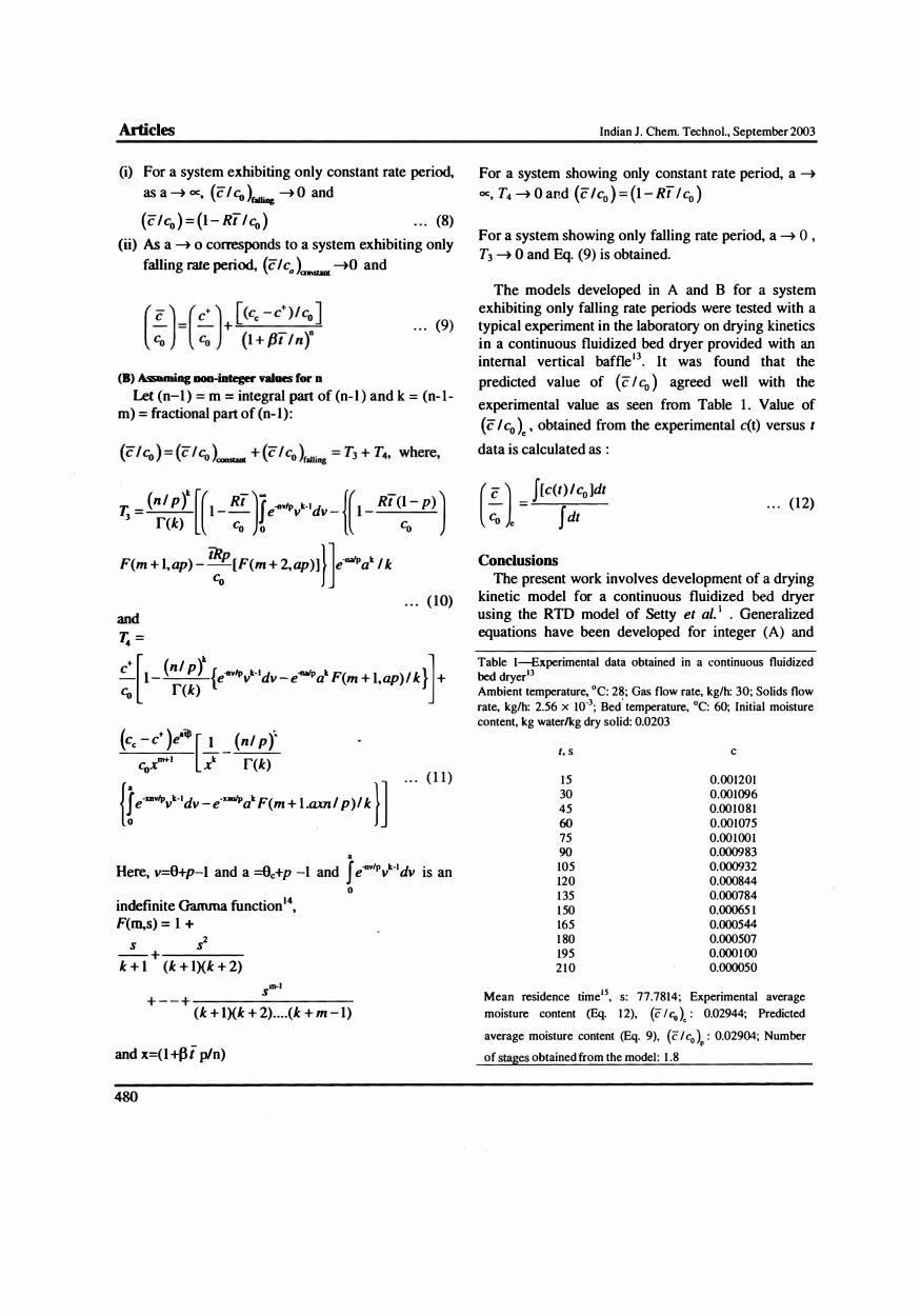
Table l�xperimental data obtained in a continuous fluidized bed dryerl3
Ambient temperature, °C: 28; Gas flow rate, kg/h: 30; Solids flow rate, kg/h: 2.56 x 10⁻³; Bed
'temperature, °C: 60; Initial moisture
content, kg waterlkg dry solid: 0.0203
t. s c
15 0.001201 30 0.001096 45 0.001081 60 0.001075 75 0.001001 90 0.000983 105 0.000932 120 0.000844 1 35 0.000784 1 50 0.00065 1 165 0.000544-1 80 0.000507 195 0.0001 00 2 1 0 0.000050
Mean residence timels• s: 77.7814; Experimental average moisture content (Eq. 1 2), (c I co). : 0.02944; Predicted
average moisture content (Eq. 9). (c I cO )p : 0.02904; Number
of stages obtained from the model: 1 .8
Setty & Murthy: Model for drying of solids
non-integer values (B) of 'n' considering both constant rate period and falling rate period and also for the limiting cases of a system exhibiting only constant rate period or only falling rate period for both cases of A and B. There is perfect agreement of predicted value of (Z I co ) for both cases of A and B with the experimental value. Hence the generalized equations can be used to predict the values of average moisture content relative to the initial moisture content, (Z I co ) . Nomenclature
c moisture content of the solid at time. t, kg
moisturelkg dry solid average moisture content .of the product, kg
waterlkg dry solid equilibrium moisture content, kg waterlkg dry solid critical moisture content of the solids. kg waterlkg dry solid
Co initial moisture content of the solids. kg waterlkg dry solid
R constant drying rate. kg waterlkg dry solid-s clock time. s mean residence time. s
time corresponding to critical moisture content, s
Greek Letters � = RI(cc - c+). sol
p, density of solids. kg/mJ
8 dimensionless time. (tl t ) 8c dimensionless time corresponding
moisture content. (II T )c
References
to critical
1 Pydi Setty Y, Kaushal Rege & Chandramouli Sastry. Indian Chem Eng, 44 (4) (2002) 246
2 Jobes C W. Chem Eng, 6 1 ( 1 ) ( 1954) 1 66 3 Frolov V F. Romankov P G & Rashkovskaya N B. Zh Priki
Khim. 37 (4) ( 1964) 824; Chem Abstr, 6 1 ( 1 964) 2747 4 Beran Z & Lutcha J. The Chem Eng. ( 1 975) 678 5 Reay D. Proc Int Symp on Drying. Montreal. Canada, 1978 6 Vanecek V. Markvart M & Drbohlav R. Fluidized Bed
Drying (Leonard Hill. London. UK). 1 966 7 Suzuki K, Fugigami A. Yamazaki R & Jimbo G, J Chem Eng
Jpn. 1 3 (6) ( 1 980) 493 8 Chandran A N, Subba Rao S & Varma Y B G. A1ChE J,
36( 1 ) ( 1 990) 29 9 Vanecek V. Markvart M. Drbohlav R & Hummel R L. Chem
Eng Prog Symp Series. 66 ( 105) ( 1970) 243 10 Pydi Setty Y, Axial mixing of solids in a spiral fluidized bed.
Ph. D. Thesis, Indian Institute of Technology. Madras. 1 983 1 1 Romankov P G, Drying, in Fluidization. edited by Davidson
J F & Harrison B. Chap. 12 (Academic Press. London). 1 97 1 1 2 Lenin Babu K & Pydi Setty Y . J Energy, Heat & Mass
Transfer. 23 (2) (2001 ) 1 35
Articles
1 3 Satish S . Modelling and simulation of a continuous fluidized
bed dryer using artificial neural networks. M Tech Thesis, Regional Engineering College, Warangal. 2000
14 Abromovitz Z M & Stegun I A, Handbook of Mathematical Functions with Formulae, Graphs and Mathematical Tables (Dover Puhlications, New York, USA), 1972. 253
15 Levenspiel O. Chemical Reaction Engineering. 2nd ed. (Wiley Eastern Limited, New Delhi). 1975. 261
Appendix
Expressions for (c I co ) can be obtained by substituting the
expression for E(O) (Eq. 2) and respective expressions for (C!cO)b for different cases.
Continuous drying of solids
(A) Assuming integer values for n For constant rate and fal1ing rate periods ( c I Co ) is obtained by
substituting Eq. (2) in Eq. ( 1 ) as:
Let T, = (c I Co )consr.n, T, = �:/��! 1 (1 - RTo I co )(O + p - It e-(nlpx9+p-I )dO
where v = (8 + p- l) and a = (8c + p - 1 ).
. . . (AI) Consider.
j Vn-Ie-(nlp)' dv o
- e + + + + . . . . . + ---':--'--_ -(nip). (n - I) ! [1 vn (vni (vn)J (vn)"- I ]
(nl p)" p l2 ! pJ3 ! p"- I (n - I) !
= (n - I)! [1 - e-(nalp)F (na I )] (A2) (n l p)"
a P . . .
where F(n.s) = Fn(s) = [1 + s + t..- + !..- + .. . + �] 2 ! 3! (n - l) !
combination of Eqs ( A I ) and (A2) yields,
On simplification. Eq. (5) can be obtained.
481
Articles
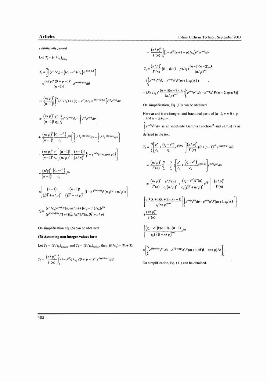
Falling rate period
Let T. = (c I c ) 2 0 falling
0. = f[ (c+ I CO) + {(c� - c+ )1 Co }e·Pt(G.j),) ] o
x (n l p)" (e + p _ l)n.1 e-(n1PXG+p-' )de (n - I) !
(nI P)" c+ [ (n - l)! (n - l)! { .nalp }] = --- --n - --n l - e F(n, anl p) (n - l)! co (n I p) (nI p)
x . . (l - e-(�la+anlp)F(n, f3r + n l p»
[ (n - l)' (n - I)1 -1 (f3r + n l p )" (f3t + n l p)"
On simplification Eq. (6) can be obtained.
(B) Assuming non.integer values for n
( I )n G T = �f' (l - Rte lc )(e + p _ I)n- ' e·(n1pX9+p-')de
3 r(n) 0 I·p
482
Indian J. Chern. Techno!., September 2003
T. = (n l P)" [(l - Rt(l - )/c ) (n - l)(n - 2) . . . k
3 r(n) p 0 (n l prl
(j e·nvlpvk· 'dv - e·nalpak F(m + l , ap)1 k ) o
On simplification, Eq. ( 10) can be obtained.
Here m and k are integral and fractional parts of (n- l ), v = 9 + P -1 and a = 9c+ p -l
j e·nvIPvk.ldv is an indefinite Gamma function l4 and F(m,s) is as o
defined in the text.
(nl p)" +-r (n)
( (Cc - c+ )k (k + l) .. . (n - I) eiJla
co (tf3 + nl pr l
On simplification, Eq. ( 1 1 ) can be obtained.