multiswitch 2012 07 19 english - aqua...
TRANSCRIPT

MULTISWITCH
Owner’s ManualOwner’s ManualOwner’s ManualOwner’s Manual
multiswitch™ 1.41Firmware-Version 1.06OS- Version 1.02
The information contained in this manual is subject to change without prior notice. All rights reserved.Current as of: Juli 19th 2012
© 2005-2012 Aqua Computer GmbH & Co. KG - 1 -Gelliehäuser Str. 1, 37130 Gleichen

MULTISWITCH
Table of ContentsTable of ContentsTable of ContentsTable of Contents
1. Contents of package.......................................................3
2. Preface..........................................................................3
3. Safety precautions...........................................................4
4. Connecting external components......................................54.1. Overview.....................................................................................54.2. Power connector...........................................................................54.3. USB.............................................................................................54.4. aquabus (I2C-Bus)........................................................................64.5. Jumpers.......................................................................................64.6. Power outputs 1/2........................................................................64.7. LED-outputs.................................................................................74.8. Relay...........................................................................................84.9. aquastream..................................................................................8
5. Configuration.................................................................9Jumper position 1: aquabus-address.....................................................9Jumper position 2: Save configuration...................................................9Jumper position 3: Deactivate PWM function .........................................9Jumper position 4: Button function......................................................10Jumper position 5: USB/aquabus........................................................10
6. Initial operation............................................................11
7. Further details...............................................................127.1. Changing the front plate..............................................................12
8. Technical Data.............................................................12
- 2 - Aqua Computer GmbH & Co. KG © 2005-2012Gelliehäuser Str. 1, 37130 Gleichen

MULTISWITCH
1. Contents of package1. Contents of package1. Contents of package1. Contents of package
1x multiswitch™ (assembled)1x internal USB-cable (5-pin), length approx. 70 cmMounting material
1x this manual
2. Preface2. Preface2. Preface2. Preface
Dear customerDear customerDear customerDear customer,
We congratulate you on the purchase of a multiswitch from Aqua Computer. We are one of the oldest manufacturers in Germany of PC water-cooling systems. Our products are made from materials of the highest quality. We hope you enjoy your new cooling system. Should you have any questions, we would like to ask you to first look at the "FAQ" area and "forum" on our homepage www.aqua-computer.de. If you should not find an answer to your question there, please email to [email protected]. Considering the fast technical development, we reserve the right to be able to perform alterations to the products at any time. It therefore is possible that your product does not correspond precisely to the descriptions or especially the illustrations in this manual.
Your Aqua Computer Team
© 2005-2012 Aqua Computer GmbH & Co. KG - 3 -Gelliehäuser Str. 1, 37130 Gleichen

MULTISWITCH
3. Safety precautions3. Safety precautions3. Safety precautions3. Safety precautions
Before we get into the specifics of the system, we would like you to follow these basic precautions which should be obeyed at all times.
1. Read this manual thoroughly and completely!
2. Backup your data before working on the hardware!2. Backup your data before working on the hardware!2. Backup your data before working on the hardware!2. Backup your data before working on the hardware!
3. The aquaero may only be used completely assembled in a3. The aquaero may only be used completely assembled in a3. The aquaero may only be used completely assembled in a3. The aquaero may only be used completely assembled in a computer case!computer case!computer case!computer case!
4. Never touch, connect or separate cables or electronic4. Never touch, connect or separate cables or electronic4. Never touch, connect or separate cables or electronic4. Never touch, connect or separate cables or electronic components while in use!components while in use!components while in use!components while in use!
5. Do not turn on your computer unless you are absolutely certain5. Do not turn on your computer unless you are absolutely certain5. Do not turn on your computer unless you are absolutely certain5. Do not turn on your computer unless you are absolutely certain that all cables are securely and correctly connected to thethat all cables are securely and correctly connected to thethat all cables are securely and correctly connected to thethat all cables are securely and correctly connected to the aquaero!aquaero!aquaero!aquaero!
6. 6. 6. 6. Maintenance notes:Maintenance notes:Maintenance notes:Maintenance notes: Use only soft, damp cloths to wipe the Use only soft, damp cloths to wipe the Use only soft, damp cloths to wipe the Use only soft, damp cloths to wipe the device. Do not use benzene, paint thinner, detergents, ordevice. Do not use benzene, paint thinner, detergents, ordevice. Do not use benzene, paint thinner, detergents, ordevice. Do not use benzene, paint thinner, detergents, or chemically treated wiped cloths, and do not place vinyl, plastic, orchemically treated wiped cloths, and do not place vinyl, plastic, orchemically treated wiped cloths, and do not place vinyl, plastic, orchemically treated wiped cloths, and do not place vinyl, plastic, or rubber objects on the device to avoid the risk of malfunction orrubber objects on the device to avoid the risk of malfunction orrubber objects on the device to avoid the risk of malfunction orrubber objects on the device to avoid the risk of malfunction or damage to surface of the device!damage to surface of the device!damage to surface of the device!damage to surface of the device!
7. The relay-output may be powered at max. 12 V! The current7. The relay-output may be powered at max. 12 V! The current7. The relay-output may be powered at max. 12 V! The current7. The relay-output may be powered at max. 12 V! The current must not exceed 1 Ampere!must not exceed 1 Ampere!must not exceed 1 Ampere!must not exceed 1 Ampere!
8. All statements in this manual are subject to the fast8. All statements in this manual are subject to the fast8. All statements in this manual are subject to the fast8. All statements in this manual are subject to the fast technological development. Our products are constantlytechnological development. Our products are constantlytechnological development. Our products are constantlytechnological development. Our products are constantly enhanced. Technical changes, misprints and errors are reserved! enhanced. Technical changes, misprints and errors are reserved! enhanced. Technical changes, misprints and errors are reserved! enhanced. Technical changes, misprints and errors are reserved!
9. This product is not designed for use in life support appliances,9. This product is not designed for use in life support appliances,9. This product is not designed for use in life support appliances,9. This product is not designed for use in life support appliances, devices, or systems where malfunction of this product candevices, or systems where malfunction of this product candevices, or systems where malfunction of this product candevices, or systems where malfunction of this product can reasonably be expected to result in personal injury. Aquareasonably be expected to result in personal injury. Aquareasonably be expected to result in personal injury. Aquareasonably be expected to result in personal injury. Aqua Computer customers using or selling this product for use in suchComputer customers using or selling this product for use in suchComputer customers using or selling this product for use in suchComputer customers using or selling this product for use in such application do so at their own risk and agree to fully indemnifyapplication do so at their own risk and agree to fully indemnifyapplication do so at their own risk and agree to fully indemnifyapplication do so at their own risk and agree to fully indemnify Aqua Computer GmbH & Co. KG for any damages resulting fromAqua Computer GmbH & Co. KG for any damages resulting fromAqua Computer GmbH & Co. KG for any damages resulting fromAqua Computer GmbH & Co. KG for any damages resulting from such application.such application.such application.such application.
10. Do not rest your weight on or place heavy objects on the10. Do not rest your weight on or place heavy objects on the10. Do not rest your weight on or place heavy objects on the10. Do not rest your weight on or place heavy objects on the ddddevice, and do not apply excessive force to the buttons, switches,evice, and do not apply excessive force to the buttons, switches,evice, and do not apply excessive force to the buttons, switches,evice, and do not apply excessive force to the buttons, switches, or connectors to avoid the risk of damage to the device oror connectors to avoid the risk of damage to the device oror connectors to avoid the risk of damage to the device oror connectors to avoid the risk of damage to the device or personal injury.personal injury.personal injury.personal injury.
- 4 - Aqua Computer GmbH & Co. KG © 2005-2012Gelliehäuser Str. 1, 37130 Gleichen
!
!
!
!
!
!
!
!
!
!
!
!
!
!
!
MULTISWITCH
4. Connecting external components4. Connecting external components4. Connecting external components4. Connecting external components
4.1. Overview4.1. Overview4.1. Overview4.1. Overview
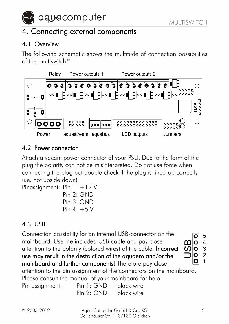
The following schematic shows the multitude of connection possibilities of the multiswitch™:
4.2. Power connector4.2. Power connector4.2. Power connector4.2. Power connector
Attach a vacant power connector of your PSU. Due to the form of the plug the polarity can not be misinterpreted. Do not use force when connecting the plug but double check if the plug is lined-up correctly (i.e. not upside down)Pinassignment: Pin 1: +12 V
Pin 2: GNDPin 3: GNDPin 4: +5 V
4.3. USB4.3. USB4.3. USB4.3. USB
Connection possibility for an internal USB-connector on the mainboard. Use the included USB-cable and pay close attention to the polarity (colored wires) of the cable. IncorrectIncorrectIncorrectIncorrect use may result in the destruction of the aquaero and/or theuse may result in the destruction of the aquaero and/or theuse may result in the destruction of the aquaero and/or theuse may result in the destruction of the aquaero and/or the mainboard and further componentsmainboard and further componentsmainboard and further componentsmainboard and further components!!!! Therefore pay close attention to the pin assignment of the connectors on the mainboard. Please consult the manual of your mainboard for help.Pin assignment: Pin 1: GND black wire
Pin 2: GND black wire
© 2005-2012 Aqua Computer GmbH & Co. KG - 5 -Gelliehäuser Str. 1, 37130 Gleichen

MULTISWITCH
Pin 3: D+ green wirePin 4: D- white wirePin 5: VCC red wire
4.4. aquabus (I4.4. aquabus (I4.4. aquabus (I4.4. aquabus (I2222C-Bus)C-Bus)C-Bus)C-Bus)
3-pin add-on connector for optional add-on components by aqua-computer. Only use cables specified by aqua-computer (not included in delivery)!Pin assignment: Pin 1: GND
Pin 2: SDAPin 3: SCL
4.5. Jumpers4.5. Jumpers4.5. Jumpers4.5. Jumpers
The five positions configure the different functions of the multiswitch™. Appropriate short-circuit-bridges, so-called „Jumpers“, are included in the delivery. The individual functions may be derived from chapter 5. Configuration.
4.6. Power outputs 1/24.6. Power outputs 1/24.6. Power outputs 1/24.6. Power outputs 1/2
Screw clamps that allow the connection of up to eight consumer loads to the power outputs of the multiswitch™. The outputs supply a maximum of 12 V at a maximal 1 amp per channel. The total load The total load The total load The total load mustmustmustmust notnotnotnot be higher than 40 Watts. be higher than 40 Watts. be higher than 40 Watts. be higher than 40 Watts. Incorrect use may result in the destructionIncorrect use may result in the destructionIncorrect use may result in the destructionIncorrect use may result in the destruction of the multiswitch™ and/or the mainboard and further components! of the multiswitch™ and/or the mainboard and further components! of the multiswitch™ and/or the mainboard and further components! of the multiswitch™ and/or the mainboard and further components!
Pin assignment: Terminal strip 1 contact 1: Output 8 +12 V enabledTerminal strip 1 contact 2: Output 8 GNDTerminal strip 1 contact 3: Output 7 +12 V enabledTerminal strip 1 contact 4: Output 7 GNDTerminal strip 1 contact 5: Output 6 +12 V enabledTerminal strip 1 contact 6: Output 6 GNDTerminal strip 1 contact 7: Output 5 +12 V enabledTerminal strip 1 contact 8: Output 5 GNDTerminal strip 2 contact 1: Output 4 +12 V enabledTerminal strip 2 contact 2: Output 4 GNDTerminal strip 2 contact 3: Output 3 +12 V enabled
- 6 - Aqua Computer GmbH & Co. KG © 2005-2012Gelliehäuser Str. 1, 37130 Gleichen
MULTISWITCH
Terminal strip 2 contact 4: Output 3 GNDTerminal strip 2 contact 5: Output 2 +12 V enabledTerminal strip 2 contact 6: Output 2 GNDTerminal strip 2 contact 7: Output 1 +12 V enabledTerminal strip 2 contact 8: Output 1 GND
NOTICE:NOTICE:NOTICE:NOTICE:
•When disabled the output voltage lies below 0,5 V
•When connecting inductive loads (e.g. motors), a self-induction recuperation diode (Schottky) and a 100 nF capacitor need to be connected to the consumer to prevent interferences with the multiswitch™ and other connected devices. In isolated cases further measures may be required.
•The outputs are notnotnotnot protected against overvoltage or short-circuits! When connecting capacitive and inductive loads appropriate precaution measures must be taken.
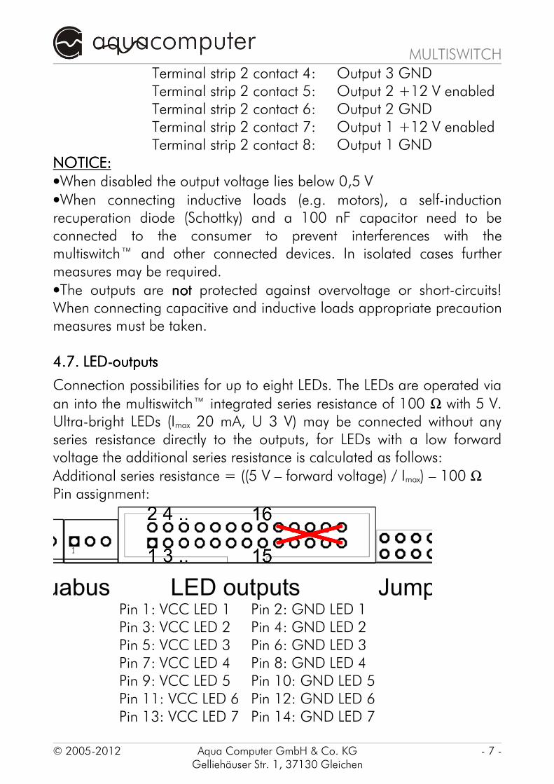
4.7. LED-outputs4.7. LED-outputs4.7. LED-outputs4.7. LED-outputs
Connection possibilities for up to eight LEDs. The LEDs are operated via
an into the multiswitch™ integrated series resistance of 100 Ω with 5 V. Ultra-bright LEDs (Imax 20 mA, U 3 V) may be connected without any series resistance directly to the outputs, for LEDs with a low forward voltage the additional series resistance is calculated as follows:
Additional series resistance = ((5 V – forward voltage) / Imax) – 100 ΩPin assignment:
Pin 1: VCC LED 1 Pin 2: GND LED 1Pin 3: VCC LED 2 Pin 4: GND LED 2Pin 5: VCC LED 3 Pin 6: GND LED 3Pin 7: VCC LED 4 Pin 8: GND LED 4Pin 9: VCC LED 5 Pin 10: GND LED 5Pin 11: VCC LED 6 Pin 12: GND LED 6Pin 13: VCC LED 7 Pin 14: GND LED 7
© 2005-2012 Aqua Computer GmbH & Co. KG - 7 -Gelliehäuser Str. 1, 37130 Gleichen

MULTISWITCH
Pin 15: VCC LED 8 Pin 16: GND LED 8All other pins (17-26) must notmust notmust notmust not be short circuited!
4.8. Relay4.8. Relay4.8. Relay4.8. Relay
Floating output. Freely usable, maximum breaking capacity 4 A at max. 12 V.Pin assignment: Pin 1: Opening contact (NC)
Pin 2: Common connectorPin 3: Breaking contact (NO)
4.9. aquastream4.9. aquastream4.9. aquastream4.9. aquastream
Connection possibility to the controller of the aquastream. A maximum of two aquastream-controller may be connected. The following chart shows the connection possibilities depending on the hardware revision of the controller:
Revision Controller 1Revision Controller 1Revision Controller 1Revision Controller 1 Revision Controller 2Revision Controller 2Revision Controller 2Revision Controller 2
1.0 or higher not possible1.5 or higher 3.0 or higher
- 8 - Aqua Computer GmbH & Co. KG © 2005-2012Gelliehäuser Str. 1, 37130 Gleichen

MULTISWITCH
5. Configuration5. Configuration5. Configuration5. Configuration
Via the five configuration-jumpers (see chapter 4.5.Jumper) you can permanently configure single functions of the multiswitch™. For this purpose the included short-circuit-bridges („jumper“) are either removed from the contact pins (position „open“) or set on the contact pins (position „closed“).The individual positions have the following functions:
Jumper position 1:Jumper position 1:Jumper position 1:Jumper position 1: aquabus-address aquabus-address aquabus-address aquabus-address
This jumper configures the aquabus-adress of the multiswitch™ when connected as a aquabus-device e.g. to the aquaero. When connected as a USB-device this function is ignored.Jumper open: Address multiswitch™ 1Jumper closed: Address multiswitch™ 2
Jumper position 2: Save configurationJumper position 2: Save configurationJumper position 2: Save configurationJumper position 2: Save configuration
When this jumper is set, the current condition of the outputs are saved with each keypress (supprted only in devices with buttons) and automatically loaded after a reset of the system . Additionally a save via the PC-software aquasuite is possible. If this function is deactivated, so is the function in the aquasuite software!Jumper open: Saving deactivatedJumper closed: Speichern activated
Jumper position 3: Deactivate PWM function Jumper position 3: Deactivate PWM function Jumper position 3: Deactivate PWM function Jumper position 3: Deactivate PWM function
This jumper configures the output of PWM signals at the outputs of the multiswitch™. In the default setting (jumper open) PWM signals are generated at the outputs which allow for instance LEDs to be controlled in brightness. You mustmustmustmust check if allallallall connected devices are able to
© 2005-2012 Aqua Computer GmbH & Co. KG - 9 -Gelliehäuser Str. 1, 37130 Gleichen

MULTISWITCH
handle PWM signals beforebeforebeforebefore you activate this function. Failure to do soFailure to do soFailure to do soFailure to do so may result in the destruction of the connected devices!may result in the destruction of the connected devices!may result in the destruction of the connected devices!may result in the destruction of the connected devices! If the multiswitch™ is used as an aquabus-device on the aquaero, the PWM function is always deactivated and the jumper setting is ignored.Jumper open: PWM activatedJumper closed: PWM deactivated
Jumper position 4: Button functionJumper position 4: Button functionJumper position 4: Button functionJumper position 4: Button function
This jumper configures the functions of the buttons on the front of the device (supprted only in devices with buttons). When the jumper is set, the condition (on/off) of the corresponding power output is switched. Additionally the outputs may be switched via the PC-software if the multiswitch™ is connected via USB (not possible if connected as an aquabus-device). With an open jumper setting the buttons have no direct influence on the outputs of the multiswitch™ and are only interpreted via the PC-software when connected as an USB-device. If the power outputs of the multiswitch™, when connected as an aquabus-device to the aquaero, should be switched, the jumper must be open!Jumper open: Interpret buttons only via the PC-softwareJumper closed: Buttons switch power outputs directly
Jumper position 5: USB/aquabusJumper position 5: USB/aquabusJumper position 5: USB/aquabusJumper position 5: USB/aquabus
This jumper configures which interface of the multiswitch is active.Jumper open: USB enabled, aquabus disabledJumper closed: aquabus enabled, USB disabled
- 10 - Aqua Computer GmbH & Co. KG © 2005-2012Gelliehäuser Str. 1, 37130 Gleichen

MULTISWITCH
6. Initial operation6. Initial operation6. Initial operation6. Initial operation
Depending on the hardware version either install the multiswitch™ in an available 5 ¼“-bay of your PC-case (version with buttons and LEDs) or in an available place in the interior of your case (version multiswitch™ LT without buttons and LEDs). Place close attention that the circuit board is securely fixed and has no conductive contact to parts of the PC-case!Now configure the functions of the multiswitch™ as described in chapter 5. Configuration.Make all desired connections to the multiswitch™ as described in chapter 4. Connecting external components and make sure that no short-circuits are present at the outputs of the multiswitch™.
The device may now be operated by starting the computer.
To conveniently operate the device the aquasuite software can be used.Software and updates may be found in the internet at http://www.aqua-computer.de in the section „Support“.
© 2005-2012 Aqua Computer GmbH & Co. KG - 11 -Gelliehäuser Str. 1, 37130 Gleichen

MULTISWITCH
7. Further details7. Further details7. Further details7. Further details
7.1. Changing the front plate7.1. Changing the front plate7.1. Changing the front plate7.1. Changing the front plate
The front plate of the multiswitch™ (not multiswitch LT™ version) can be exchanged for different colored plates (not included in delivery). To do this, simply unscrew the four mounting screws in the corners, change the front plate and carefully retighten the screws.
8. Technical Data8. Technical Data8. Technical Data8. Technical Data
Dimensions (WxHxD): approx. 148x42x64 mmCurrent consumption 5V: typ. 5 mACurrent consumption 12 V (plus power output): typ. 10/150 mA (LT/non LT)Load capacity per power output: max. 10 WTotal load capacity for all outputs: max. 40 WLoad capacity of the relay output: max. 12 V, max. 4 A
- 12 - Order code 93391 *AC93391* © 2005-2012