mucool status and plans - brookhaven national … · mucool overview and plans muon cooling r&d...
TRANSCRIPT

MUTAC 04 - April 28-29 2004A. Bross
MuCool Overview and Plans
Muon Cooling R&DMUTAC 04A. Bross
MUTAC 04 - April 28-29 2004A. Bross
This Review
• MuCool presentations for this afternoonOverview BrossNCRF LiRF Studies TorunLH2 Absorber Windows CummingsLH2 Absorber Tests IshimotoCooling Channel Instrumentation ErredeGaseous Cooling Johnson

MUTAC 04 - April 28-29 2004A. Bross
The MuCool Collaboration
• MissionDesign, prototype and test all cooling channel componentsPerform high beam-power engineering test of cooling sectionSupport MICE (cooling demonstration experiment)
• Consists of 18 institutions from the US, Europe, and Japan
RF DevelopmentANLFermilabIITJLABLBNLUniv. of Mississippi
Beam DiagnosticsANLFermilabIITPrincetonUniv. of Chicago
Absorber R&DFermilabIITKEKNIUOxfordUIUCUniv. of MississippiUniv. Osaka
Cooling Demonstration (MICE)ANLBNLFermilabFairfieldIITIowaJLabLBNLNIUUCLAUC RiversideUIUCUniv. of ChicagoUniv. of Mississippi
SolenoidsLBNL

MUTAC 04 - April 28-29 2004A. Bross
MuCooL Management Structure
• Spokesperson and Technical Area Leaders:
Spokesperson: Alan BrossTechnical Area Leaders:
RF: Al Moretti, FNALDerun Li, LBNL
RF Diagnostics: Yagmur Torun, IITAbsorbers: Mary Anne Cummings, NIUMuCooL Test Area: Milorad Popovic, FNAL

MUTAC 04 - April 28-29 2004A. Bross
SFOFO Cooling Lattice
• R&D Focus of MuCoolComponent testing Fermilab
High Power– Both RF and Beam
System test - MICE @ RAL
2001
2002
2003 2004
MUTAC 04 - April 28-29 2004A. Bross
Research and Development Challenges
• Can NCRF cavities be built that provide the required accelerating gradients?
AND operate in multi-tesla fields!• Can the heat from dE/dx losses be adequately removed from the
absorbers?On the order of 100’s W for a neutrino factory
• Can the channel be engineered with an acceptably low thickness of non-absorber material in the aperture?
Absorber, RF, & safety windows• Can the channel be designed & engineered to be cost effective?

MUTAC 04 - April 28-29 2004A. Bross
MuCool Test Area
The MuCooL Collaboration Enters a new Era“Escape from the Wilderness”
MUTAC 04 - April 28-29 2004A. Bross
MuCool Test Area
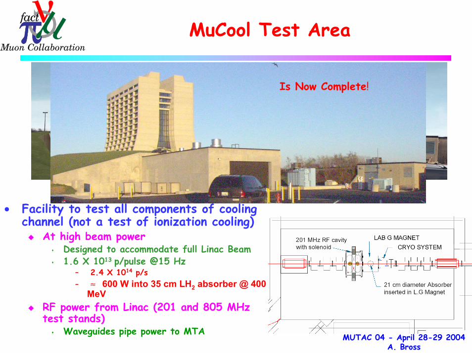
• Facility to test all components of cooling channel (not a test of ionization cooling)
At high beam powerDesigned to accommodate full Linac Beam1.6 X 1013 p/pulse @15 Hz
– 2.4 X 10¹⁴ p/s– ≈ 600 W into 35 cm LH2 absorber @ 400
MeVRF power from Linac (201 and 805 MHz test stands)
Waveguides pipe power to MTA
Is Now Complete!

MUTAC 04 - April 28-29 2004A. Bross
MTA
• The MTA is becoming our focus of ActivityLH2 Absorber testsRF testing (805 and 201 MHz)Finish Cryo-InfrastructureHigh pressure H2 gas absorbersHigh Intensity Beam

MUTAC 04 - April 28-29 2004A. Bross
MTA Tour
Compressor RoomAccess Pit

MUTAC 04 - April 28-29 2004A. Bross
MTA Tour
H2 Buffer TankH2 Manifold Room

MUTAC 04 - April 28-29 2004A. Bross
MTA Tour
Access Pit

MUTAC 04 - April 28-29 2004A. Bross
MTA Tour
MTA ExperimentalHall

MUTAC 04 - April 28-29 2004A. Bross
MTA Tour
KEK LH2 Absorber

MUTAC 04 - April 28-29 2004A. Bross
MTA Tour
MTA ExperimentalHall
From Linac(Lots of Activity)

MUTAC 04 - April 28-29 2004A. Bross
MTA Tour
View from Wilson HallRF Trench visible

MUTAC 04 - April 28-29 2004A. Bross
MTA – Near Term Schedule

MUTAC 04 - April 28-29 2004A. Bross
MTA – RF Configuration
Lab G Magnet
KEKAbsorber
Currently plan to operate either RF or LH2/H2 tests, but not bothsimultaneously. We are discussing with the Laboratory how we canwork in both modes simultaneously.

MUTAC 04 - April 28-29 2004A. Bross
Towards Experimental Hall
Refrigerator RoomRefrigerator Room
• Tevatron satellite refrigerator to be operated on 5 K mode and 14 K mode (3” DE, 3” WE)
• Helium and nitrogen Dewar
Compressor RoomCompressor Room• Two 400 HP 2-stage oil injected screw compressors
Transfer line connections to experimental hall which includes 5K, 20K, 80K circuits
Heat exchanger
MTA Cryo-Infrastruture
MUTAC 04 - April 28-29 2004A. Bross
MTA High Intensity Beam
ML -
0 3
ML-
0 2
ML-
0 1
TOR
OID
NO
.2
624
S 00-01-19.2 W
612.
459
600
576
552
528
504
480
456
432
408
384
360
R.F
LAN
GE
OU
T PO
RT
ML -
01
TUR
BO P
UM
P
PG
-MV1
LAM
BER
TSO
N
PORT
ML -
01
ION
PU
MP-
OU
T
537 .
80
449 .
7 753
367.
236
ENCLOSURES SHOWN AS APPROXIMATE ONLY
ND
B p
B AR
TR
I M
BEL
LOW
S 29
9899
MV
1
BEL
LOW
SB P
M5
Q4
TRIM
2
MW
2
BEL
L OW
S
BE
LLO
WS
MH
1
MV
0
BPM
4
Q3
200
Me V
TYP
E
TRI M
1
PUMPS OMITTED FROM PLAN VIEW.
29.689 29.481 15.52210°
8°
MTA
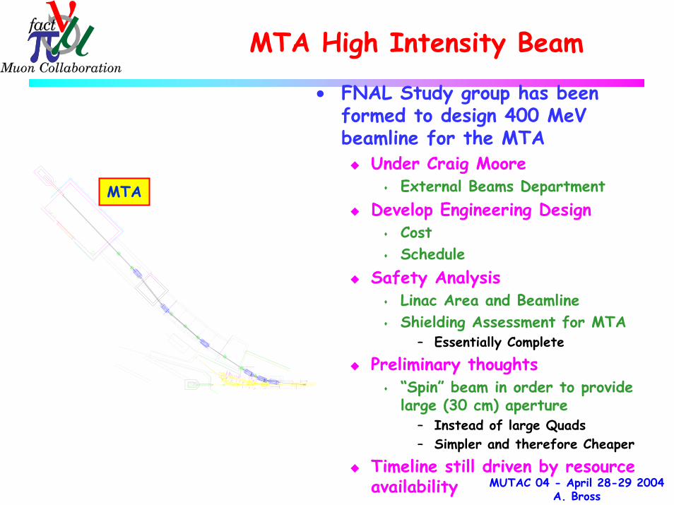
• FNAL Study group has been formed to design 400 MeVbeamline for the MTA
Under Craig MooreExternal Beams Department
Develop Engineering DesignCostSchedule
Safety AnalysisLinac Area and BeamlineShielding Assessment for MTA
– Essentially Complete
Preliminary thoughts“Spin” beam in order to provide large (30 cm) aperture
– Instead of large Quads– Simpler and therefore Cheaper
Timeline still driven by resource availability

MUTAC 04 - April 28-29 2004A. Bross
MTA Shielding Assessment
• Conclusions from Present StudyA credible beam accident at MTA is less severe than normal operation.At normal operation the following classification is suggested (Fermi RCM):• Berm above target hall –Controlled Area of minimal occupancy (0.25 – 5 mrem/hr);• Access pit – Radiation Area with rigid barriers/locked gates (5 – 100 mrem/hr);• Cryo room - Radiation Area with rigid barriers/locked gates (5 – 100 mrem/hr);• Compressor room - Controlled Area of minimal occupancy (0.25 – 5 mrem/hr);• Parking lot – Normal (not controlled) area (dose rate below 0.05 mrem/hr).
MUTAC 04 - April 28-29 2004A. Bross
RF Cavity R and D
ANL/FNAL/IIT/LBNL/UMiss

MUTAC 04 - April 28-29 2004A. Bross
RF Cavity R&D – Prototype Tests
• Work to date has focused on using 805 MHz cavities for test
Allows for smaller less expensive testing than at 201 MHzLab G work at Fermilab
• Unfortunately due to a Klystron failure in the Linac, the Lab G Klystron had to be moved back to the Linac
As of December 25, 2003 the Lab G facility ceased operation
• We are now moving as rapidly as possible (with a great deal of support from the Fermilab Beams Division) to bring up 805 and 201 MHz RF test capability to the MTA
Moving Vacuum, power, etc systems to MTAMove Magnet to MTA
Lab G RF Test Cave showing 5T SC Magnet44 cm bore
R.I.P.

MUTAC 04 - April 28-29 2004A. Bross
RF Cavity R&D – Quick Review
• Open cell cavity reached peak surface field of 54 MV/m (25 on axis)
Large dark currentsDamage to windowsPunctured Ti window in worst case
• Closed Cell (single) cavityB=0, Cu window – Low Bkg.
Reached 34MV/mWith B field
TiN coated Be window (0.01”)Initially conditioned to 16MV/m
– Dark currents then roseHowever, no damage in evidence to Be
– Copper contamination• From iris/flange surface
At 8MV/m dark currents very low– Acceptable for MICE
Closed CellCu window

MUTAC 04 - April 28-29 2004A. Bross
RF Cavity Closed Cell Magnetic Field Studies
• Data seem to follow universal curve
• Sparking limits max gradient
• Copper surfaces the problem
Peak Magnetic Field in T at the Window
Grad
ient
in
MV/
m

MUTAC 04 - April 28-29 2004A. Bross
RF R&D – 201 MHz Cavity Design
• Design Complete and Fabrication well under wayExpect Epk
surf = 19 MV/m (17 MV/m on axis)Now has curved windowsGoal is to have a 201 MHz cavity under test at Fermilab in the Fall
Cavities in Coupling Coil

MUTAC 04 - April 28-29 2004A. Bross
RF R&D – 201 MHz Cavity DesignTube-Grid Aperture Study
• Finite Element analysis of tube grid design
First applied to electromagnetic model of 805 MHz cavity
For Lab G test
Grid Model Electric Field Magnetic Field
Maximum Surface Field Enhancement
4x4-Connected 3.60
4x4 -Waffle2.30 1.80
6x6 -Waffle1.64 1.40 1.39
6x6 Middle-Concentrated/Waffle 1.40
Tube DIA (cm)Grid 0.50 1.00 1.25 1.50Thesis work of
Mohammad M. Alsharo’aIIT

MUTAC 04 - April 28-29 2004A. Bross
Absorber R and D
IIT/KEK/NIU/Osaka/Oxford/UIUC/UMiss

MUTAC 04 - April 28-29 2004A. Bross
Absorber Design Issues
• 2D Transverse Cooling
and
• Figure of merit: M=LRdEµ/dsM2 (4D cooling) for different absorbers
Absorber Accelerator Momentum loss is opposite to motion, p, px, py, ∆E decrease
Momentum gain is purely longitudinal
Large emittance
Small emittance
H2 is clearly Best -Neglecting Engineering Issues
Windows, Safety

MUTAC 04 - April 28-29 2004A. Bross
Absorber Design Issues
• Design CriteriaHigh Power Handling
Study II – few 100 W to 1 KW with “upgraded” (4MW) proton driver10 KW in ring cooler
– Must remove heat
Safety issues regarding use of LH2 (or gaseous H2)
Window design paramount– H2 containment
Proximity to RF adds constraints (ignition source)
Window material must be low Z and relatively thin in order to maintain cooling performance H2 implies engineering complexity

MUTAC 04 - April 28-29 2004A. Bross
Absorber R&D
• Two LH2 absorber designs are being studied Handle the power load differently
Forced-Convection-cooled. Has internal heatexchanger (LHe) and heater – KEK System
Forced-Flow with external cooling loop

MUTAC 04 - April 28-29 2004A. Bross
Convection Absorber
• Convection is driven by beam power and internal heaters
• LHe heat exchanger removes heat from absorber walls
• Two-dimensional Computational Fluid Dynamics calcs
Flow essentially transverseMax flow near beamHeaters required to setup convective loops

MUTAC 04 - April 28-29 2004A. Bross
Forced-Flow Absorber
• Heat removed with external heat exchanger
LH2 pumped from absorber to heat exchangerNozzles in flow path establish turbulent flowSimulation via 2D and 3D FEA

MUTAC 04 - April 28-29 2004A. Bross
Absorber Windows
Containment Windows
Vacuum
• Thin windows are required in all absorber designs
Critical design issuePerformanceSafety
First examples made with AL T6061Maybe even thinner with
Al-Li alloy - 2195
Absorber
Design IterationHemiSpherical – Inflected(Now also used for RF)
MUTAC 04 - April 28-29 2004A. Bross
Gaseous Absorber – Muons Inc
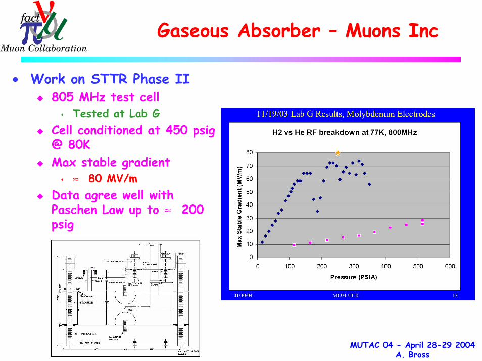
• Work on STTR Phase II805 MHz test cell
Tested at Lab GCell conditioned at 450 psig @ 80KMax stable gradient
≈ 80 MV/mData agree well with Paschen Law up to ≈ 200 psig

MUTAC 04 - April 28-29 2004A. Bross
Beam line Instrumentation
• CVD DiamondFor beam diagnostics can be very thin
Lots of charge – 36 e-h/µm-mipRad HardLow-quality (small mfp) might be useableFirst prototypes have been tested
Very Fast (limited by electronics)Large signalSome of the diamond is approx. linear over full intensity range (3 X 10¹¹ e-/cm2)
– Needs more study
• MTA InstrumentationIntrinsically safe solution
Temperatures, Magnet currents, BPMs.Local readout (PC) + ACNET

MUTAC 04 - April 28-29 2004A. Bross
Simulation Work
• Cooling Components as mentionedAbsorbers – 2D and 3D Finite Element Analysis (FEA)
2D Computational Fluid Dynamics (CFD)RF – Electromagnetic modeling of Be windows and grids
FEA modeling of window deflection/stress• Quad-focused cooling channel• Study II cooling channel
GEANT4 simulation including latest window design• MICE
GEANT4 framework developed

MUTAC 04 - April 28-29 2004A. Bross
MuCool and MICE
• Muon Ionization Cooling Experiment (MICE)Demonstration of “Study II” cooling channel concept
• MuCool Collaboration interface to MICEDesign Optimization/develop of Study II cooling channel
SimulationsDetailed engineering
Full component designSystems integrationSafety
RF cavity development, fabrication, and testAbsorber development, fabrication, and testDevelopment of beam line instrumentationMuCool will prototype and test cooling hardware including MICE pieces for which the collaboration is responsible
• High-intensity Beam Tests are responsibility of MuCool and are, of course, fully complementary to MICE
MUTAC 04 - April 28-29 2004A. Bross
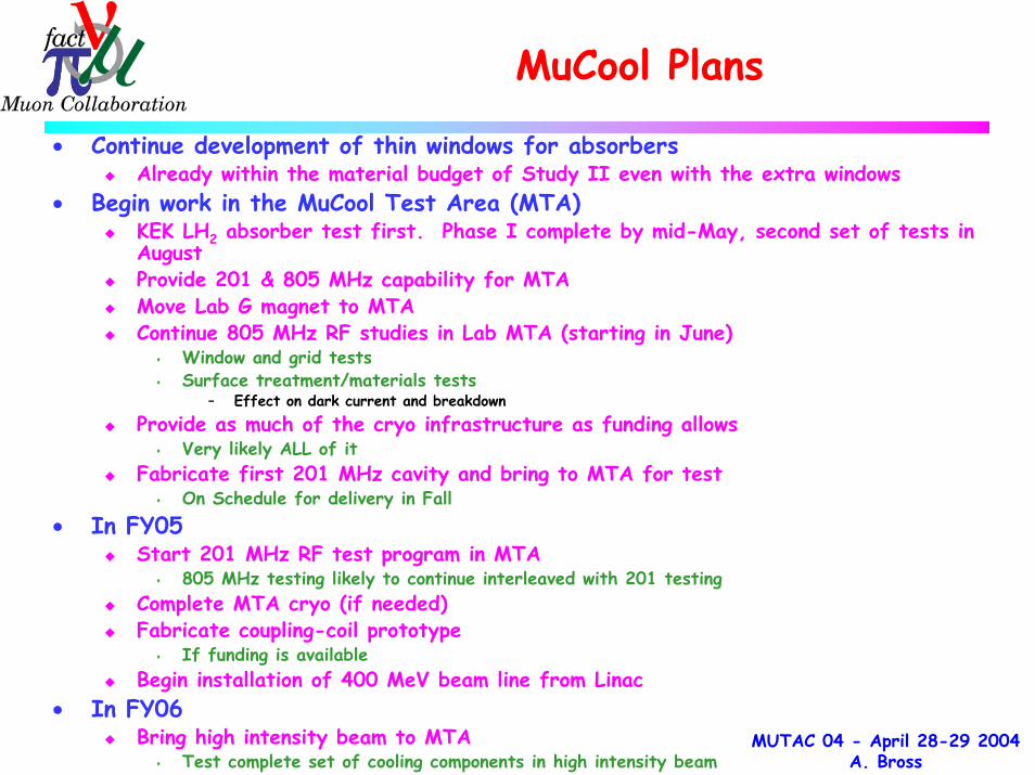
MuCool Plans
• Continue development of thin windows for absorbersAlready within the material budget of Study II even with the extra windows
• Begin work in the MuCool Test Area (MTA)KEK LH2 absorber test first. Phase I complete by mid-May, second set of tests in AugustProvide 201 & 805 MHz capability for MTAMove Lab G magnet to MTAContinue 805 MHz RF studies in Lab MTA (starting in June)
Window and grid testsSurface treatment/materials tests
– Effect on dark current and breakdown
Provide as much of the cryo infrastructure as funding allowsVery likely ALL of it
Fabricate first 201 MHz cavity and bring to MTA for testOn Schedule for delivery in Fall
• In FY05Start 201 MHz RF test program in MTA
805 MHz testing likely to continue interleaved with 201 testingComplete MTA cryo (if needed)Fabricate coupling-coil prototype
If funding is availableBegin installation of 400 MeV beam line from Linac
• In FY06 Bring high intensity beam to MTA
Test complete set of cooling components in high intensity beam

MUTAC 04 - April 28-29 2004A. Bross
Conclusion
• Excellent progress has been made in the last yearMTA is complete
On budget and on schedule– HVAC is late
Absorber testing underwayRF test program to begin in June (805 and then 201 in Fall)
– NCRF R&D has demonstrated High Gradient low dark current operation– R&D continues in order to continue to push HG Low DC operation in B field– Use of Be RF windows looks promising
Design of LH2 absorbers and windows has matured“Thin” window required spec appears to have been met
Detailed engineering of components has matured• MuCool is a thriving International Collaboration
Absorbers – JapanAbsorber/Window design – UKAddressing many of the needs of MICE