mr. trevor lloyd, senior planner december 15, 2017 mr
TRANSCRIPT

1
Mr. Trevor Lloyd, Senior Planner December 15, 2017
Mr. Dwayne Smith, Senior Engineer
Washoe County Planning Department
1001 E. 9th Street, Reno, NV 89512
Subject: Lumos Associates Field Geotechnical Investigation September/October 2017
Dear Trevor and Dwayne:
This letter transmits our professional observations of the limited geotechnical work done on the Ascenté
property last September/October in support of Condition for Approval 7.5 (Lumos and Associates, August
4, 2017). The professional geologists and geotechnical engineers living in the Callahan neighborhood have
concerns regarding the technical quality and accuracy of geologic and geotechnical data interpretation
being compiled by Lumos "in support" of this project's approval conditions. Specifically, we are concerned
that the data gathered is sparse and not adequate to map the existing faulting on the property and that
evidence of this faulting might be misinterpreted or be misleadingly discussed in their final reporting. We
won’t know for certain until Lumos submits their final report, however, as a community, we have no more
input in the approval process. We must rely on a knowledgeable review of the report by the County
Planners. The County must demand an accurate interpretation of the trenching, drilling, and logging data.
This may require expertise not available within the office.
Some of us have had conversations with the Lumos civil engineer and exploration geologist assigned to
conduct trenching, drilling and "soils surveys" on the Ascenté property. The civil engineer relayed that
the geologist logging the trenches, found a couple of faults but they are "over a million years old". We
find this incredulous for the reasons listed below. Additionally, we have noted several other professional
discrepancies and concerns during our observations of the field activity conducted by Lumos last fall that
we wish to relay to the Planning Department in advance of further Ascenté Project evaluations.
1) First and most importantly, we noted that there was no evidence that OSHA regulations pertaining
to trenching safety were being adhered to. The trenches we observed had not been shored and no
shoring material was evident on site. We also observed that the trenches were backfilled within a day,
with the exception of the two trenches we were able to view. This indicates to us that Lumos did not
take the time to shore these trenches and to log them according to accepted geologic/geotechnical
practices, as described further below. The OSHA regulations pertaining to trench digging and logging
safety requirements are detailed in the link below:
https://www.osha.gov/Publications/osha2226.pdf
2) Basic structural geology indicates that a fault that bisects geologic formation/formations must be
younger than the geologic material it bisects. The Mount Rose Piedmont or Fan is dated at Tahoe Age
or older (generally 100,000 years, according to Alan Ramelli's paper, as attached. Therefore, any faulting
logged within the Mt. Rose fan must be younger than Tahoe Age, and could quite possibly be Holocene,

2
particularly if it shows expression at or near the surface. It stands to reason that no fault in this area can
be "over a million years old" and be found in Tahoe Age and younger sediments at ground surface unless
it is still active, in which case it must be characterized as a Holocene fault, and thus be further located and
mapped on subject property.
3) Chip Porter and I visited the trench dug on the western property border along the dirt access road.
We could see the fault as evidenced by the change in lithology, as shown in the photos below and suggest
that it is the concealed fault previously identified by the NV Division of Mines and Geology. Chip noted
that the trench wall was not shored even though it was over 8 feet deep, and the wall was not scraped
smooth to better reveal the fault scarp and related geologic materials changes within it, as is professional
practice. We don't have the Lumos trench logs but we understand from our on-site conversations with
the Lumos contract geologist, Frank, that he logged several trenches in one day! Chip states that during
his professional practice as an engineering geologist, he logged around 100 feet of trench per day, given
good conditions and uncomplicated geology. It is not plausible that the trenches could be adequately
logged so quickly. Photos of the trench walls showing the observed fault are included below.
Photo 1 – South wall of trench along west side of Ascenté property boundary, showing fault trace, as
seen by change in sediment color. NOTE were not scraped smooth, as is good professional practice.

3
Photo 2 – Trench cuttings revealing lithology change at the central west side of property, just south of
Brushwood Way.

4
Photo 3 - Fault trace in trench just south of Brushwood Way on west side of Ascenté property. If the
trench walls had been scraped smooth, the changes in the rock facies would have been more apparent.
Below please find a list of procedures followed in conduct of geologic/geotechnical trench logging and
mapping:
Trenching Procedures
1 – Identification of active fault or active fault segment
2 – selection of trenching based on preliminary determination of possible fault locations from existing
mapping.
4 – Site and Trench Safety Procedures
*Shoring of trench walls
*Construction of fence surrounding trench site
5 – Prepare of trench walls for mapping by cleaning and smoothing trench walls
6 – Gridding of trench walls
7 – Marking sites of datable material for fault age-dating

5
8 – Marking sites of features be mapped with colored nails
9 – Measuring displacement along trench wall
10 – Mapping trench walls
11 – Precisely marking end points of faults
12 – Sampling and packaging of datable material. Send samples to a reliable laboratory for Cacrbon 14-
dating
13 – Backfilling trench
Photo 4 – Example photo of a trench wall with flagging and reference net. In this trench across the Irpinia fault (Southern Italy) the fault zone appears as a warping of sediments and ground surface. As shown in Photo 4, the trench wall is scraped or cleaned to reveal lithology and geologic features.
Important features are highlighted by painted nails or little colored flags, called “pinning or flagging”.
Another important step in preparing a trench for detailed geologic mapping is the setting of a horizontal

6
and vertical grid formed by squares of a pre-determined width (feet or meters) outlined by string or twine.
These serve as a reference for logging trench walls and for correlating features to other trenches at the
same site.
4) The northernmost trench, located up against the hillside on the northeast edge of the Ascenté
property was dug several feet to the west of the obvious dip in ground surface, a dip which could suggest
a fault zone, and thus would require further investigation. Also, to conduct an accurate and geologically-
sound trenching effort, the trench should have been dug right up against the hillside to reveal the geologic
material comprising the hillside, as well as the structural dip in the ground surface. It appeared that either
the geologist didn't study the area carefully enough, or didn't realize that geotechnical accuracy would
entail extending the trench up to the base of the hillslope (where, if a fault exists, the change in lithology
would be obvious). Effectively, the trenches are dug where the faults don’t appear to be. We suggest
that a trench be dug at the location of the proposed access road as it is planned to ascend the hillslope so
that the existence of a fault can be noted, or ruled out. This is very important as the proposed access
road is planned by Ascenté to be build up that hillslope and would be impacted by a Holocene fault.
5) On September 29, we observed the contents of a drill core box left at a drilling site on the
southwest corner of the property, about 200 feet south of the water tank access road. I took photos of
the core and noted that labeling on the boxes left much to be desired. The core rock labeling, and the
condition of the core itself indicates that drilling hit fault gouge at 8 feet, and then fresh fractured
diorite/andesite bedrock from 10 - 20 feet. Both of these features indicate the presence of a fault. No
core was collected after that depth but the core box doesn’t indicate that 20 feet is the final depth. The
hole was at least partially filled with bentonite chips and then the empty bag was stuffed over top. It
wasn't apparent whether the drillers poured water down hole to activate the bentonite and thus seal the
drillhole. Three photos of this core are shown below.

7
Photo 5 – Core Box from drillsite at southwest Ascenté property, south of Patti Lane.

8
Photo 6 – Core box contents at 8 feet depth, evidence of fault gouge.

9
Photo 7 – Core “loss” at 0 – 8 feet. Why was core not collected from the surface to 8 feet?
It appeared that some of the fractures in the core at the 8-foot zone had slick surfaces, suggesting
movement. Did or any of the other planer zones in this drillcore or core from the other drillholes contain
fractures and/or slickensides? A slickenside is a smoothly polished surface caused by frictional movement
between rocks along the two sides of a fault. Sometimes the drill bit hits a fracture zone or groundwater
fracture flow boundary and the drill rod washes out with no intact core. Did they core fractured rock from
0 to 8 feet, or soil, or solid rock? Detailed drilling and core logging records, if professionally done, will
record this information which is important for foundation planning.
6) Because this project requires a huge amount of blasting and rock removal, we do hope that rock
core was collected for strength testing, including laboratory tests such as P-wave, Schmidt Hammer, Point-
load, and direct shear testing (ASTM D5607). The final Lumos report should include clear identification
and classification of samples and specimens and photo documentation of samples and specimens sent for
laboratory testing. The samples must be representative of rock that is to be blasted and moved during
construction.
7) We strongly suggest that Lumos invite a State Geologist to the site and to aid them in accurately
interpreting the data collected this very important geotechnical field work. Additionally, the County
Planning department should employ an experienced engineering geologist, or geotechnical engineer to
direct all geotechnical investigations conducted in support of development planning for Washoe County.

10
The safety of current and future homeowners is dependent on a robust evaluation of seismic and
geotechnical conditions on this property (and all proposed development properties) and a complete and
accurate evaluation of seismic hazards due to the presence of Holocene faulting throughout Washoe
County. I am also attaching Chip Porter's letter to you dated December 10, 2016, in which he details
sound professional practice for geotechnical investigations.
Thank you for your time and attention to our concerns.
Sincerely,
Kris Hemlein
Attachments: Ramelli, R. "Paleoseismic studies of the Little Valley Fault" Final Technical Report
Edward Porter Letter to the County Commissioners December 10, 2016

11
U.S. Geological Survey Earthquake Hazards Reduction Program
Final Technical Report
Paleoseismic studies of the Little Valley fault Grant Award No. 02HQGR0103
Alan R. Ramelli, Craig M. dePolo, and John W. Bell
Nevada Bureau of Mines and Geology
University of Nevada, Reno, NV 89557
(775) 784-4151
(775) 784-1709 FAX [email protected]
Program Element: I
Key Words: Trench Investigations, Fault Segmentation,
Quaternary Fault Behavior, Paleoseismology
Background
The frontal fault system that bounds the northern Carson Range in western Nevada (referred to as
either the northern Carson Range fault system (NCRFS) or the Mt. Rose fault zone) is a major fault
system that poses the principal seismic hazard to Reno, the second most populous area in the state.
There is more than 5,000 ft (1,500 m) of topographic relief across the NCRFS, but only a part of this relief
occurs across the range-front fault trace. Much of this relief occurs across faults within the range, across
a highly distributed piedmont fault zone, or as warping. In this project, we tried to assess how activity is
distributed across the system.
The NCRFS extends from southernmost Washoe Valley northward into downtown Reno (figure 1), for an
overall length of ~34 km. In Washoe Valley, the zone includes an 11-km long frontal fault (Washoe
Valley fault) and a major, subparallel fault within the Carson Range (Little Valley fault); taken together,
these two faults have a length of ~17 km.
To the north, the fault system includes an 8-km long frontal fault, several synthetic faults within the
Carson Range, and a complex, distributed zone of nested graben in the hanging wall (total length of ~25
km, and a width of up to 10 km). The fault system extends to downtown Reno as a narrow graben,
sometimes referred to as the Virginia Lake fault zone.

12
13
Figure 1: Generalized map of the northern Carson Range fault system
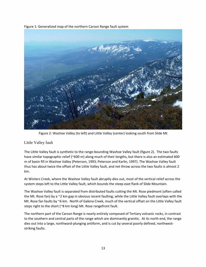
Figure 2: Washoe Valley (to left) and Little Valley (center) looking south from Slide Mt
Little Valley fault
The Little Valley fault is synthetic to the range-bounding Washoe Valley fault (figure 2). The two faults
have similar topographic relief (~600 m) along much of their lengths, but there is also an estimated 600
m of basin fill in Washoe Valley (Peterson, 1993; Peterson and Karlin, 1997). The Washoe Valley fault
thus has about twice the offset of the Little Valley fault, and net throw across the two faults is almost 2
km.
At Winters Creek, where the Washoe Valley fault abruptly dies out, most of the vertical relief across the
system steps left to the Little Valley fault, which bounds the steep east flank of Slide Mountain.
The Washoe Valley fault is separated from distributed faults cutting the Mt. Rose piedmont (often called
the Mt. Rose fan) by a ~2 km gap in obvious recent faulting, while the Little Valley fault overlaps with the
Mt. Rose fan faults by ~6 km. North of Galena Creek, much of the vertical offset on the Little Valley fault
steps right to the short (~8 km long) Mt. Rose rangefront fault.
The northern part of the Carson Range is nearly entirely composed of Tertiary volcanic rocks, in contrast
to the southern and central parts of the range which are dominantly granitic. At its north end, the range
dies out into a large, northward-plunging antiform, and is cut by several poorly defined, northwest-
striking faults.
14
Investigations undertaken
*Examined several geotechnical consultants’ trenches, and logged three trenches that yielded
radiocarbon age control on the most recent event.
*Constructed topographic profiles across faults within the northern Carson Range in order to estimate
relative offsets
*Constructed topographic profiles across the Mt. Rose piedmont fault zone and within the city of Reno
from two-foot contour data available from Washoe County
*Compiled and re-evaluated age constraints for the fault system as a whole
Results
Mt. Rose fan trenches
The Mt. Rose fan area is undergoing extensive development, mostly residential, and consulting
companies have excavated many trenches in the area for geotechnical studies associated with
development projects. Dozens of trenches have been examined in reconnaissance fashion over the
years. The vast majority of these trenches revealed little other than evidence of generally small (tens of
cm) recent offsets, but a few trenches have yielded datable material constraining the timing of the most
recent event.
Callahan Ranch trenches
Two out of 18 trenches excavated for a development project in the Callahan Ranch area revealed
fissures formed during the most recent surface rupturing event. These fissures are filled with dark,
organic-rich material, presumably derived from mollic soil horizons present at the time of faulting. If
mean residence time (MRT) uncertainties can be adequately accounted for, these dates should
approximate the age of the event.

15
Figure 3: Locations of the five trenches in the southern Mt. Rose fan area that have yielded datable
material. WC-1, excavated in the early 1980s (Schilling and Szescody, 1982; Bell and others, 1984),
yielded constraints on the MRE. WC-2, a consultants’ trench excavated in the 1990s, yielded two bulk
radiocarbon dates from colluvial deposits that at least generally indicate the fault’s rate of recent
activity. Trenches 12 and 15, consultants’ trenches excavated in the early 2000s, yielded radiocarbon
dates that support the estimated age of the MRE from WC-1. FT06, a consultants’ trench excavated in
2007, yielded detrital charcoal in a fissure formed during the MRE (results are pending).
Callahan Ranch Trench 15
Trench 15 was excavated across an antithetic fault scarp just west of Steamboat Hills. With a height of
~10 m (estimated vertical displacement of 8-12 m), this is one of the largest fault scarps in the Mt. Rose
fan area.
Trench 15 revealed relations that are fairly typical of fault scarps on the Mt. Rose piedmont, where fan
deposits generally have thick, well-developed argillic soils, indicating fairly old ages (>100 ka). The scarp
faces themselves also commonly have well-developed soils, indicating they have existed for a minimum

16
of several tens of thousands of years. The soil on the Trench 15 scarp is not as well-developed as in
some other locations, likely because the large, steep scarp face is not entirely stable. Similar to many
other Mt. Rose piedmont fault scarps, the scarpmantling soil is displaced by one or more recent faulting
events.
The deposits exposed in Trench 15 generally consisted of massive gravelly sands. The lack of distinct
stratigraphy limited interpretation of events, but relations nonetheless indicate several events with up
to a few meters of offset per event. The only datable material obtained from the trench was dark,
organic-rich material within a fissure formed by the most recent event, which yielded a radiocarbon date
of 1,060 + 70 ybp (figure 4).
Figure 4: Log of Callahan Ranch Trench 15. See figure 3 for trench location.
Callahan Ranch Trench 12
Trench 12 was excavated across a small, synthetic fault scarp in the central part of the Callahan Ranch
graben (figure 3). In contrast to the repeated events revealed in Trench 15, Trench 12 displayed only a
single recent event offsetting a well-developed argillic soil. However, similar to Trench 15, Trench 12
exposed dark, organic-rich material filling a fissure formed during the most recent event. The sample
yielded a radiocarbon date of 930 + 60 ybp, virtually identical to the date from Trench 15 and a prior
radiocarbon date from the mouth of Whites Creek canyon (Szecsody and Schilling, 1982).

17
Figure 5: Sketch log of Callahan Ranch Trench 12. See figure 3 for trench location.
Montreaux trench FT06
Trench FT06, excavated across an antithetic fault in the Montreaux area (figure 3) during Summer, 2007,
exposed detrital charcoal within a fissure formed during the most recent event. One of two charcoal
samples was submitted for dating, and results are pending. Dating of detrital charcoal avoids some of
the mean residence time (MRT) issues involved in dating bulk soil samples, so it is hoped that this
sample will either support the estimated age of the MRE based on results from the other trench sites, or
reveal whether the prior radiocarbon dates are significantly affected by MRT factors.
The event sequence in FT06 was complicated by both the bouldery nature of the fan deposits, and by
erosion and subsequent deposition caused by fault-parallel drainage, so no detailed attempt was made
to interpret event stratigraphy.

18
Figure 6: Sketch log of Montreaux trench FT06. See figure 3 for trench location.
Faults within the Northern Carson Range
Several subparallel faults cut the northern Carson Range (figure 7). These faults are within the footwall
of the range-front fault, and most strike NNW, slightly oblique to the range front. Most of these faults
are synthetic to the range front (down-to-the-east displacement), and in general, these faults decrease
in displacement away from the frontal fault.

19
Figure 7: Escarpment heights (in feet) along principal faults within the northern Carson Range.
The two largest faults (F and C) have maximum escarpment heights of about 900 ft (270 m) and 720 ft
(220 m), respectively, and cut alluvial deposits in Thomas Creek canyon. Blue shading – estimated
maximum extent of the late Pleistocene glacier in Thomas Creek canyon. Grey shading – major
Quaternary landslide areas.

20
Figure 8: Topographic profile 1, crossing faults within the northern Carson Range. Profile line is located
at ~39.4146 deg N, about 1 mi north of Thomas Creek canyon. For estimating vertical separations,
surfaces are projected horizontally because here the range is composed of volcanic rocks that are
presumed to have been originally flat lying. However, the volcanic rocks are moderately tilted, especially
toward the range front, and vertical separations are thus a combination of faulting and tilting. Vertical
exaggeration - 1.8X.

21
Figure 9: Locations of topographic profiles 2, 3, and 4 (see figure 10). Blue shading – estimated extent of
late Pleistocene glaciers in Whites Ck (top) and Galena Ck (bottom); eastern extents of both are
uncertain. Glaciation was more extensive than shown in the Mt. Rose summit area, but only the main
source area for Galena Creek is depicted. Dashed outline – Quaternary landslides.
Figure 10: Topographic profiles and estimated vertical separation (in feet) across faults within the
Carson Range. Profile 2 (top) and profile 3 (middle) cross the Little Valley fault at Slide Mt.
Profile 4 (bottom) extends along the crest of the right lateral glacial moraine at Whites Creek.
See figure 9 for profile locations. Vertical exaggeration – 1.8X.

22
Topographic Profiling in the Mt. Rose fan and Reno areas
The Mt. Rose piedmont (commonly called the Mt. Rose fan) is dominated by glacial outwash deposits of
Tahoe age or older (generally >100ka). The piedmont is broadly warped and cut by a series of
subparallel, nested graben (compare figures 1, 3, and 7). The southern part of the piedmont is
characterized by a 2.5-km wide nested graben separating Steamboat Hills from the Carson Range. North
of Steamboat Hills, the piedmont fault zone is about 7 km wide and includes at least five subparallel,
sygmoidal graben. These two sections appear to be separated by a northwest-striking, antithetic fault
zone. This northwest-striking fault has a left-stepping pattern, suggesting a right-lateral component, and
it may also truncate the range-front fault.
Figure 11: Low sun angle photograph of the Callahan Ranch area, southern Mt. Rose fan
A persistent feature of the Mt. Rose piedmont fault zone is a relatively narrow (~0.5 km wide), linear
zone of graben, generally located a little more than 1 km east of the range front. This discontinuous
zone includes the central part of the Callahan Ranch graben (figure 7) and extends north into Reno,
forming the Virginia Lake fault zone (figure 1).

23
The Mt. Rose piedmont fault zone includes both synthetic and antithetic faults. To evaluate net
displacements across the zone, more than 40 topographic profiles were constructed from twofoot
contour data available from Washoe County. http://www.washoecounty.us/gis
Profile locations are shown on figures 12-14, best-estimate displacement calculations are shown in Table
1, and representative profiles are shown in figures 15-20.
Limitations:
*Fan surfaces are not perfectly planar
*Many of the surfaces are relatively old (>100 ka) and thus variably eroded
*Surfaces are in places greatly altered by urban development
*Surfaces on either side of a fault (or graben) commonly have different slopes (with the up-slope surface
typically being steeper)
*Surface ages are poorly constrained
*Differing age surfaces are present on either side of faults in some locations *Further work
on ranges of uncertainty is needed
The topographic profiles generally reveal little to no net vertical displacement across the entire zone,
although locally net displacement appears to be down-to-the-west (i.e., antithetic to the range front) .
The largest fault scarps generally are antithetic faults forming the east side of the main graben zone, but
this is due at least in part to a lack of scarps on old surfaces along the range front. The one location
where old surfaces are preserved along (or near) the range front has comparable sized scarps (figure
19).
General observations:
1) Scarps on “Tahoe-aged” surfaces along the range-front fault trace show fairly similar offsets of
6-9 m (figure 15).
2) Profiles of the Callahan Ranch graben (figure 16) show little net displacement. The central part
of the graben generally has a small down-to-the-east displacement, but if the main antithetic
fault is included, displacement is down-to-the-west.
3) Profiles of the main antithetic fault (figures 17, 18) show significant down-to-the-west
displacement, but in most locations there is no comparable-age synthetic scarp along the range-
front trace, so net displacement is problematic.
4) The most complete set of profiles crossing (almost) the entire zone (figure 19) suggests there is
a small amount of down-to-the-east net displacement across the zone as a whole, but more
work to determine whether these profiles cross similar-aged surfaces, as mapped, is warranted.
5) To the north, profiles at Virginia Lake show slight down-to-the-east displacement, but even
further north there is clearly a larger amount of down-to-the-west displacement (figure 20).
Table 1: Mt Rose piedmont fault zone: profile summary
profile fault trace VS (ft) corr.*
net disp (ft)
net disp
(m) map surf
est age (ka) slip rate
(m/ka) Thomas Creek 2 range front 55 1.2 66 20.1 Qdm 300 0.067 Thomas Creek 1 range front 16 1.2 19.2 5.9 Qtm 100 0.059 Whites Creek 1 range front 18 1.2 21.6 6.6 Qtm 100 0.066

24
Whites Creek 2 range front 18 1.2 21.6 6.6 Qtm 100 0.066 Whites Creek 3 range front 20 1.2 24 7.3 Qtm 100 0.073 Galena 1-1 range front 25 1.2 30 9.1 Qmb 100 0.091 Galena 1-2 range front 21 1.2 25.2 7.7 Qgo2 100 0.077 Galena 2 antithetic 1 17 1.1 18.7 5.7 Qgo2 100 -0.057 Galena 3-1 antithetic 1 30 1.1 33 10.1 Qgo2 100 -0.101 Galena 3-2 antithetic 1 6 1.1 6.6 2.0 N/A 20 -0.101 Browns Creek 1 graben 22 1.1 24.2 7.4 Qgo2 100 -0.074 Browns Creek 2 graben 8 1.1 8.8 2.7 Qgo2 100 -0.027 Callahan Ranch 1 graben 12 1.1 13.2 4.0 Qtm 100 -0.040 Callahan Ranch 2 graben 18 1.2 21.6 6.6 Qgo2 100 0.066 Callahan Ranch 3B graben 19 1.2 22.8 6.9 Qtm 100 0.069 Lower Whites 1-1 graben 0 1.1 0 0.0 Qtm 100 0.000 Lower Whites 1-2 graben 12 1.2 14.4 4.4 Qtm 100 0.044 Callahan Ranch 1 antithetic 2 23 1.15 26.45 8.1 Qtm 100 -0.081 Callahan Ranch 2 antithetic 2 19 1.15 21.85 6.7 Qgo2 100 -0.067 Callahan Ranch 3A antithetic 2 34 1.15 39.1 11.9 Qtm 100 -0.119 Lower Whites 2 antithetic 2+3 60 1.1 66 20.1 Qdm? 300 -0.067 Saddlehorn 1 antithetic 3 40 1.1 44 13.4 Qdm 300 -0.045 Saddlehorn 2 antithetic 3 19 1.1 20.9 6.4 Qtm? 100 -0.064 Arrowcreek 1 antithetic 4 25 1.1 27.5 8.4 Qdm 300 -0.028 Dry Creek 1A antithetic 4 64 1.1 70.4 21.5 Qdm 300 -0.072 Dry Creek 1B antithetic 4 78 1.1 85.8 26.2 Qdm 300 -0.087 Dry Creek 2A antithetic 4 30 1.1 33 10.1 Qdm 300 -0.034 Dry Creek 2B antithetic 4 8 1.1 8.8 2.7 Qp 300 -0.009 Dry Creek 3 synthetic 12 1.2 14.4 4.4 Qp/Qoa 300 0.015 Windy Hill South antithetic 4 8 1.1 8.8 2.7 N/A 100 -0.027 Wolf Run 1 graben 16 1.2 19.2 5.9 Qdm 300 0.020 Virginia Lake 1 graben 10 1.2 12 3.7 Qdo 300 0.012 Virginia Lake 2 graben 5 1.2 6 1.8 Qdo 300 0.006 Holcomb 1 graben 40 1.1 44 13.4 Qdo 300 -0.045 Holcomb 2 graben 15 1.1 16.5 5.0 Qdo 300 -0.017 Holcomb 3 graben 35 1.1 38.5 11.7 Qdo 300 -0.039
*correction factor assuming 60 deg fault dip and 4 deg surface slope

25
Figure 12: Locations of topographic profiles, southern Mt. Rose fan.

26
Figure 13: Locations of topographic profiles, northern Mt. Rose fan.

27
Figure 14: Locations of topographic profiles, southwest Reno.

28
Figure 15: Topographic profiles across the Mt. Rose range-front fault trace.

29
Figure 16: Topographic profiles across antithetic fault and central graben, southern Mt. Rose fan

30
Figure 17: Topographic profiles across the main antithetic fault zone

31
Figure 18: Topographic profiles across the main antithetic fault in the vicinity of Dry Creek.

32
Figure 19: Topographic profile transect, generally parallel to Thomas Creek.

33
Figure 20: Topographic profiles across the northernmost CRFS in southwest Reno Summary of age
constraints
Age analyses for the Carson Range fault system as a whole were compiled and re-evaluated. The
radiocarbon dates interpreted to provide the closest constraints on timing of the two most recent
events on the Carson Range fault system are depicted in figure 21. These results suggest the most

34
recent event is somewhat older along the northern part of the system than to the south (i.e., Genoa
fault); alternatively, this apparent difference may be due to mean residence time (MRT) complications
in radiocarbon dating. The penultimate event is less well constrained, but the results nonetheless
show that the entire system has ruptured twice within the last couple thousands of years.
Figure 21: Summary of radiocarbon age-control for the Carson Range fault system.
Blue=samples postdating MRE; red=samples predating MRE; yellow=samples approximating MRE;
green=samples postdating penultimate event; orange=samples predating penultimate event. Dark
colors=1 sigma ranges; light colors=2 sigma ranges.
Non-technical Summary: The frontal fault system bounding the northern Carson Range in western
Nevada poses the principal seismic hazard to Reno, the second largest city in the state. In this area, the
fault system is broad and complex, and much of the more than 1,500 m (5,000 ft) of topographic relief
between the Carson Range and Truckee Meadows (Reno basin) occurs across faults within the range or
on the Mt. Rose alluvial fan, or as warping. In this project, we tried to assess how activity is distributed
across the system, and examined several trenches to better constrain ages of faulting.
Three consultants’ trenches yielded age constraints on the most recent event. Two of these support
prior data indicating an event ~1,000 yr ago; results from the third trench are pending. Topographic
profiling of faults within the Carson Range show that two faults generally account for most of the offset
within the range. With up to 270 m (900 ft) of displacement, these two faults have substantial offset,
but they are nonetheless much smaller than the range front fault. Profiling of faults on the Mt. Rose fan

35
and within Reno show only a small amount of down-tothe-east displacement, and locally displacement
may actually be down-to-the-west.
Reports published: None
Availability of seismic, geodetic, or processed data: Not applicable.
References
Bell, J.W., 1984, Quaternary fault map of Nevada - Reno sheet: Nevada Bureau of Mines and Geology
Map 79, scale 1:250,000.
Bell, J.W. and Garside, L.J., 1987, Geologic map of the Verdi 7½-minute Quadrangle: Nevada Bureau of
Mines and Geology Map 4Gg, scale 1:24,000.
Bell, J.W., Slemmons, D.B., and Wallace, R.E., 1984, Roadlog for Neotectonics of Western Nevada (Field
Trip 18), in J. Lintz, Jr. (editor), Geological Society of America, 1984 Annual Meeting Guidebook,
Western Geological Excursions, v. 4, p. 425-472.
Bingler, E.C., 1974, Earthquake hazards map - Reno Quadrangle: Nevada Bureau of Mines and Geology
Map 4Ai, scale 1:24,000.
Bonham, H.F., and Bingler, E.C., 1973, Geologic map of the Reno Quadrangle: Nevada Bureau of Mines
and Geology Map 4Ag, scale 1:24,000.
Peterson, R.C., 1993, Geophysical applications to the development of a groundwater model of Washoe
Valley, Nevada: unpublished M.S. thesis, University of Nevada, Reno.
Peterson, Ronald and Karlin, Robert, 1997, A hydrogeologic framework of Washoe Valley, Nevada from
joint gravity and magnetic modeling and terrain conductivity data: Proceedings of the
Symposium on the Application of Geophysics to Environmental and Engineering Problems
(SAGEEP), v. 1997, p. 511-521.
Ramelli, A., Bell, J., Caskey, S., dePolo, C., Guerrieri, L., and Yount, J., 2000, Belt-like behavior of surface-
rupturing earthquakes in the western Basin and Range Province: Geological Society of America,
Abstracts with Program, v. 32, p. A-462.
Ramelli, A.R., Bell, J.W., dePolo, C.M., and Yount, J.C., 1999a, Large-magnitude, late Holocene
earthquakes on the Genoa fault, west-central Nevada and eastern California: Seismological
Society of America Bulletin, v. 89, no. 6.
Ramelli, A.R., dePolo, C.M., and Bell, J.W., 1999b, Paleoseismic studies of the northern Sierra Nevada
frontal fault zone: final technical report to U.S. Geological Survey, National
Earthquake Hazards Reduction Program (NEHRP), award #1434-HQ-97-GR-03043.
Ramelli, A.R., and dePolo, C.M., 1997, Trenching and related studies of the northern Sierra Nevada
range-front fault system: final technical report to U.S. Geological Survey, National Earthquake
Hazards Reduction Program (NEHRP), award #1434-95-G-2606.

36
Reimer, P. J., Baillie, M. G. L., Bard, E., Bayliss, A., Beck, J. W., Bertrand, C. J. H., Blackwell, P. G., Buck, C.
E., Burr, G. S., Cutler, K. B., Damon, P. E., Edwards, R. L., Fairbanks, R.
G., Friedrich, M., Guilderson, T. P., Hogg, A. G., Hughen, K. A., Kromer, B.,
McCormac, F. G., Manning, S. W., Ramsey, C. B., Reimer, R. W., Remmele, S.,
Southon, J. R., Stuiver, M., Talamo, S., Taylor, F. W., van der Plicht, J., and
Weyhenmeyer, C. E., 2004, IntCal04 Terrestrial radiocarbon age calibration, 26 - 0 ka BP:
Radiocarbon, v. 46, p. 1029–1058.
Schilling, J. and Szecsody, G.C., 1982, Earthquake hazard maps, Mt. Rose NE and Reno NW
7½-minute quadrangles: Nevada Bureau of Mines and Geology, Final Technical Report, U.S.
Geological Survey National Earthquake Hazard Reduction Program, contract no. 14-08-0001-
19823, 63 p.
Soeller, S.A. and Nielsen, R.L., 1980, Geologic map of the Reno NW Quadrangle: Nevada Bureau of Mines
and Geology Map 4Dg, scale 1:24,000.
Stuiver, M., and Reimer, P. J., 1993, Extended 14C database and revised CALIB radiocarbon calibration
program: Radiocarbon, v. 35, p. 215–230.
Szecsody, G.C., 1983, Earthquake hazards map of the Mt. Rose NE Quadrangle: Nevada Bureau of Mines
and Geology Map 4Bi, scale 1:24,000.
Tabor, R.W., and Ellen, S., 1975, Geologic map of the Washoe City Folio: Nevada Bureau of Mines and
Geology Environmental Series, Washoe Lake Area, scale 1:24,000.
Tabor, R.W., Ellen, S., and Clark, M.M., 1978, Geologic Hazards Map of the Washoe City Folio: Nevada
Bureau of Mines and Geology Environmental Series, Washoe Lake Area, scale 1:24,000.

37
Edward Porter 5560 Wildwood Dr.
Reno, NV 89511 (775) 233-6691
December 10, 2016 Washoe County Commissioner’s c/o Bob Lucey 1001 East 9th Street Reno, NV 89512 Trevor Lloyd, Sr. Planner Washoe County Planning Department 1001 East 9th Street Reno, NV 89512 Subject: Objections to Ascent’e Tentative 635 Acre Development Plan This letter outlines my objections to the Ascent’e development plan that has been submitted by NNV1 Partners LLC for your review and consideration. I am a long time resident of Callahan Ranch having lived here since 1988. I am also a retired Geological Engineer and Environmental Manager in the State of Nevada and former owner of Porter Geotechnical a geotechnical engineering firm which has, as part of our routine work prepared geotechnical reports such as the one presented by Lumos and Associates for this development. As a retired engineer I have numerous concerns regarding the scope of technical reports prepared thus far which have not addressed significant geologic and engineering concerns with the project as it currently proposed. As a resident I am also concerned about the negative impact this project will have on the quality of life for residents of my community and on the negative impact this project will have on our property values. Technical Issues Fault Hazards: A 2011 Nevada Bureau of Mines and Geology (NBMG) Report has mapped several faults crossing the site . The west Steamboat Hills hill front fault based on its topographic expression as observed in Low Sun Angle Aerial Photography and some field checking. The fault is classified as concealed due to surface land disturbance (development). The exact location or activity has not been established with any studies to date. An older report prepared by NBMG in 1983 , Earthquake Hazards of the Mt Rose Quad shows several faults crossing the site area, see attached map. The inferred location of one of these faults passes directly thru the highest cluster of proposed home sites located at the south end of Fawn Lane. If in fact this is fault is found thru fault exploration trenching work to be an

38
active fault it will have a significant impact on how home sites can be built in this area given the required structural setback needed from the fault. Other potentially active, less than 100,000 yr old faults project into the site from the north. It should be noted that the recent Napa California earthquake was centered on what was believed to be a potentially active and not active fault. I have explored some of the faults in the Callahan area within the same tensional block that divides the subject property from the Mount Rose tectonic block. I have thru my exploration confirmed active faults in this region and have assigned building and utility setbacks from them. Later studies conducted by other consultants for The Estates Development also found active faults in the area just west of Fawn Lane. Clearly these faults need to have detailed exploration before any further consideration is given to approval of this project. Grading and Slope/Engineered Fill Stability: The June 2016 Geotechnical Research report prepared by Lumos is by there own descriptiona literature research report and does not include any site specific testing. Considering the steepness of the slopes proposed for development and the fact that almost all the higher portions of this site will be founded on bedrock, in a faulted setting, including very hard rock, the economic feasibility of this project remains in question. Lumos correctly states that excavation into the rock particularly for confined excavations for utilities could very will require blasting. Blasting could be in locations directly above existing residents. Continuous blast monitoring stations will be needed for the protection of existing residents located downhill of blast areas to assure no damage to them or their structure. Blasting and excavation in hard rock will generate a large quantity of angular rock boulders. These materials, because of the size cannot be used in engineered fill because of the problems with nesting and creation of large voids in any fill. At this point it is not known whether a sufficient quantity of fill soil of suitable size for use as engineered fill can be generated with on site excavation. If not, large quantities of soil may need to be imported in order to create proposed building pads. The import of these material would add greatly to construction traffic. Importing soil for fill could make the project financially unfeasible. Ripability studies should be conducted prior to site design to establish the extent that blasting will be necessary. It has been customary as of recent to use the large rock generated from rock slope excavations for retaining walls on the lower side of building pads and roads in areas that are graded for tracts in hillside developement. This should not be permitted. My firm had investigated numerous failures of Rock Retaining Walls in various hillside subdivisions in Sparks. The failures occur in one of two ways, either by movement of the rock itself, a particular concern given the seismic environment at this location. I have also observed failure where fines in the foundation fill soil hydraulic pipe down between the rocks creating soil movement (flow) toward downslope locations. The loss of foundation support resulted in cracking of flatwork and building foundations. There is no engineered standard for rock wall construction, such as there is for precast concrete structures. Rock wall performance depends to a large extent on the level of care in the placement of the rock. The walls are subject to failure placing existing structures including existing Calhan residents located below such walls at great risk particularly during a seismic event. Another concern is that the surface of areas retained by rock walls cannot be revegetated, thereby creating a far greater visual impact from the development. Washoe County should stipulate that no rock walls be used in the construction of this project. Runoff: The Ascent’e project will have a substantial impact on areas downslope from the increase in storm water runoff. Hard surfaces from roofed area, roadways and hard compacted soils will create a directed flow, which will place existing downslope properties at risk. Residents of Callahan have already been impacted by runoff from The Estates project forcing the engineer to comeback and redesign and

39
build a much larger storm water management system. My home was one of the homes that was impacted from that failure having lost my driveway culvert from the increased flows. The current plan for Ascent’e is considerably undersized. We have observed these so called infiltration basins recently built for The Estates. These basins were filled nearly to capacity with the one storm we had this past week. This occurred without any snow to melt on the ground surface. Design of storm water systems in this area must not be made using rainfall records alone as this will lead to a substantially under designed system. It must include a consideration for two scenarios. One is the combination of 100 yr rain event falling on a melting heavy snowpack. It must also take into account peaks from summer flash flood events which can yield several inches of rainfall in just a few hours or even minutes. For the protection of all downstream properties the proposed stormwater management system must be increased to account for peak flows that could be generated from either of these two scenarios. Personal Homeowner Issues As a longtime resident of this area I have observed the rural nature of life in the Callahan area continue to erode with each new large development built around us. While all of these projects have had some impact, none has had the impact this project will bring as the neighborhood clearly would no longer be rural in nature. The followings cites the major concerns I and many of my neighbors have with regard to this development. Public Land Access: For the people who live in Callahan and Fawn lay we access public lands in the Steamboat hills area thru three earth roads that all pass thru the development area. This area is the recreation backyard for us. We frequently either drive our quad, 4X4 truck, UTV or ride our horse or simply walk our dogs on these roads up to the public lands. One look at the heavily used earth roads will confirm this. The trail system Assent’e proposes is not practical and clearly is located up very steep slopes where it will not interfere with the marketing of the lots on their development. Such so called trails are too steep for horses and probably many hikers, and doesn’t accommodate the people who drive onto the mountain with trucks, quads or UTV’s. It also doesn’t provide for parking at the trailheads. The project will, in effect cut off our community from direct public land access and would force many people to drive to another access point. We will no longer be able to walk or ride directly from our home to access public land. The trail system, as proposed, is laid out to accommodate marketability of the project and will not meet the needs of all current users of the public lands. As such a plan that meets the needs of all users must be prepared prior to project approval. Property Values: Because of this project I have contacted a realtor about selling my home. I would prefer to stay in my home if the right measures are put in place to protect existing homeowner’s interest. My home has “great mountain views” of Steamboat Hills. I have been advised by my realtor that I must disclose to any prospective buyer about this project and that I will not be able to list as mountain views as this property will soon be developed. Therefore my property values and marketability has already been impacted by this development as we will no longer be able to advertise in our listing “mountain views”. Traffic: Development plans call for the construction of 32 foot wide road ways that funneles into streets that are as narrow as 24 feet in the Callahan area. This obviously will create a safety problem when faster moving traffic on the wider streets enters our narrow streets. In addition the pavement thickness for our streets is not designed for this increase in loading, leading to premature pavement failure. Residents of our development should not be subjected to this increase, particularly the heavy

40
truck traffic that is associated with construction. This project should have its own dedicated access directly off Mount Rose Highway, with only emergency access granted thru the Callahan area. If that for some reason is not possible our streets should be upgraded to the same standard used in the proposed development. Safety: Callahan residents were recently ordered to evacuate because of Washoe Valley fire. In the early 1980s fire actually burned brush in the corner of my lot. Fire is a real threat to this area and has threatened us several times since living here. Development has cut out all access roads but one, for residents to escape. It took some residents an hour to get out for this recent fire. Any additional traffic loads in time of emergency could easily result in the loss of life. If a fire is racing up the west slopes of the Steamboat hills residents at the top of the new development could be trapped. Safety above all is the most important reason that Ascent’e obtain direct access to the project off Mount Rose Highway. School and Public Service Funding: Washoe County residents soon will be paying extra sales tax to help fund development. I really believe placing the burden of development should be paid for by the developer. A Verdi developer has recently volunteered to pay an “impact fee” for each residential lot for his development. Why should existing residents continue to get stuck with paying for new development? The costs should be paid by the developer who will pass the cost to new residents of the area. The County should request a community service impact fee to offset cost for all expansion of public services for this project. Water: My well and many other wells in my neighborhood dried up due directly to pumping groundwater from deeper larger diameter community supply wells drilled in this neighborhood. I have been forced to connect up to public water supply. This is not just a local in must be a concern for all of southern Washoe County. We know that water rights on which so much of the development expansion is based on, is substantially over allocated in the times of extended draught such as we have experienced for many of the recent years. How can the County continue to approve projects of this size without first having real water not paper water in hand. Please call if you would like to discuss my concerns further. Edward “Chip” Porter Nevada Geological Engineer 7843 (Inactive) Nevada Environmental Manager EM-1035