movidrive mdx61b edition internal synchronous operation...
TRANSCRIPT
MOVIDRIVE® MDX61BInternal Synchronous Operation (ISYNC)
Edition
02/2004
Manual1125 2626 / EN

SEW-EURODRIVE

Manual – MOVIDRIVE® MDX61B Internal Synchronous Operation 3
1 Important Notes...................................................................................................... 4
2 System Description................................................................................................ 52.1 Application fields ............................................................................................ 52.2 Functional description .................................................................................... 52.3 State machine of internal synchronous operation.......................................... 62.4 Controlling internal synchronous operation.................................................... 7
3 Project Planning..................................................................................................... 83.1 Application examples ..................................................................................... 83.2 Requirements............................................................................................... 113.3 Project planning notes ................................................................................. 123.4 Synchronous start / stop .............................................................................. 13
4 Installation ............................................................................................................ 144.1 Software....................................................................................................... 144.2 Connection of encoder and resolver ............................................................ 154.3 Connecting incremental encoder master to MOVIDRIVE® slave................. 164.4 Connecting MOVIDRIVE® master to MOVIDRIVE® slave........................... 184.5 Connecting absolute encoder master to MOVIDRIVE® slave...................... 194.6 System bus connection of master/slave....................................................... 21
5 Operating principle and functions...................................................................... 225.1 Controlling internal synchronous operation.................................................. 225.2 Main state machine...................................................................................... 225.3 Startup cycle mode control........................................................................... 245.4 Synchronous operation ................................................................................ 305.5 Offset cycle type .......................................................................................... 345.6 Stop cycle state machine ............................................................................. 375.7 Virtual encoder ............................................................................................. 385.8 Important notes ............................................................................................ 42
6 Startup................................................................................................................... 456.1 General information ..................................................................................... 456.2 Preliminary work........................................................................................... 456.3 Starting up internal synchronous operation.................................................. 466.4 Internal synchronous operation startup interface......................................... 52
7 System Variables ................................................................................................. 63
8 Sample IPOSplus® Programs ............................................................................... 678.1 Example 1 .................................................................................................... 678.2 Example 2 .................................................................................................... 718.3 Example 3 .................................................................................................... 77
9 Index...................................................................................................................... 83
00
I
00
I
Pi
fkVA
Hz
n
4 Manual – MOVIDRIVE® MDX61B Internal Synchronous Operation
1 Important Notes
1 Important Notes
Documentation • Read through this manual carefully before you commence installation and startup ofMOVIDRIVE® drive inverters with internal synchronous operation.
• This manual was written assuming that the user has access to and is familiar with theMOVIDRIVE® documentation, in particular the MOVIDRIVE® system manual.
• In this manual, cross references are marked with "→". For example, (→ Sec. X.X)means: Further information can be found in section X.X of this manual.
• A requirement of fault-free operation and fulfillment of any rights to claim underguarantee is that you observe the information in the documentation.
Bus systems General safety notes on bus systems:
This communication system allows you to match the MOVIDRIVE® drive inverter to yourspecific application to a very high degree. As with all bus systems, there is a danger ofinvisible, external (as far as the inverter is concerned) modifications to the parameterswhich give rise to changes in the inverter’s behavior. This may result in unexpected (notuncontrolled) system behavior.
Safety and warning notes
Always observe the safety and warning notes in this publication!
• This manual does not replace the detailed operating instructions!
• Only electrical specialists are allowed to perform installation and startupobserving applicable accident prevention regulations and the MOVIDRIVE®
operating instructions!
Electrical hazardPossible consequences: Severe or fatal injuries.
Hazard Possible consequences: Severe or fatal injuries.
Hazardous situationPossible consequences: Slight or minor injuries.
Harmful situationPossible consequences: Damage to the unit and the environment.
Tips and useful information.

Manual – MOVIDRIVE® MDX61B Internal Synchronous Operation 5
2Application fieldsSystem Description
2 System Description2.1 Application fields
The internal synchronous operation function enables a group of motors to be operatedat a synchronous angle in relation to one another or with an adjustable proportionalrelationship (electronic gear). Internal synchronous operation is particularly suited to thefollowing sectors and applications:
• Beverage industry
– Filling stations
• Multiple column hoist
• Synchronous material transport
• Extruder applications, cutting to length material off the roll
– Flying saw– Rotating knife
• Packaging systems
Advantages of internal synchro-nous operation
• Possibility of position-dependent synchronization → smooth synchronizing withoutovershooting
• Possibility of position-dependent offset
• Signed input of the master gear factor
• Possibility of synchronizing with a virtual encoder
• Possibility of synchronized SBus connection between master and slave
• Software solution → no option card required
2.2 Functional description
The internal synchronous operation function is a special firmware/technology function,which only expects increments from a master. The master can either be
• the X14 input or
• any IPOSplus® variable (virtual master drive), for example in conjunction with theSBus or a virtual encoder.
Synchronization The time-controlled synchronization mechanism has been implemented. A variationbetween the angle of the slave drive and the master drive resulting from free running isreduced to zero.
In addition, a special type of synchronization can be employed. The slave drive movesat a synchronous angle to the master drive following a specified number of masterincrements (position-dependent synchronization). In this synchronization type, the slavedrive moves with a quadratic ramp.
Synchronous operation
Synchronous operation comprises various functions. For example, it is possible tooperate with a specified offset over a specific travel distance. The offset between themaster and slave drive comes into effect after a specified number of master increments.
Decoupling The slave exits synchronous operation. This process can be triggered manually bysetting a system variable, or event-driven by an external signal.
6 Manual – MOVIDRIVE® MDX61B Internal Synchronous Operation
2 State machine of internal synchronous operationSystem Description
2.3 State machine of internal synchronous operation
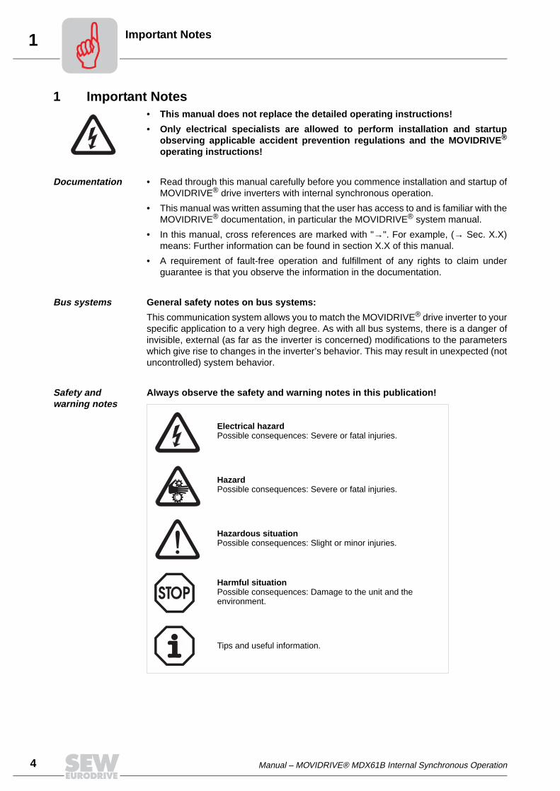
The individual functions of internal synchronous operation are controlled using a statemachine. The state machine has the six main states shown in the following figure (→Sec. 6 "Operating Principle and Functions").
6 Main states The state machine distinguishes between the six states Z0 to Z5 (→ Sec. 6 "OperatingPrinciples and Functions").
• State Z0 = Free mode n-control
The slave drive moves in free running mode with speed control. The reference to themaster drive can be stored in a difference counter.
• State Z1 = Free mode x-control
The slave drive stops with position control and therefore does not drift out of position.The reference to the master drive can be stored.
• State Z2 = Coupling state
The slave drive is synchronized to the master drive either time controlled or position-dependent.
06628AENFigure 1: Overview of the state machine for internal synchronous operation
Free moden-control
Z0
SynchronousdriveZ3
Free modex-control
Z1
Coupling stateZ2
Engaging control orIPOS program
Stop cycle stateZ5
Offset cycle stateZ4
Engaging control orIPOS program
Decoupling control orIPOS program
IPOS program
Decoupling control orIPOS program
Offset controlor IPOS program
Automatictransfer
Automatictransfer
Automatictransfer
Automatictransfer

Manual – MOVIDRIVE® MDX61B Internal Synchronous Operation 7
2Controlling internal synchronous operationSystem Description
• State Z3 = Synchronous drive
The slave drive moves synchronously with the master drive.
• State Z4 = Offset cycle state
In synchronous operation, an offset can be set either time-controlled or position-dependent.
• State Z5 = Stop cycle state
The slave drive exits synchronous operation.
2.4 Controlling internal synchronous operation
Internal synchronous operation is controlled using IPOSplus® variables within theIPOSplus® application program. All states can be viewed and set in a variable range fromH360 to H446, which is reserved for internal synchronous operation.
8 Manual – MOVIDRIVE® MDX61B Internal Synchronous Operation
3 Application examplesProject Planning
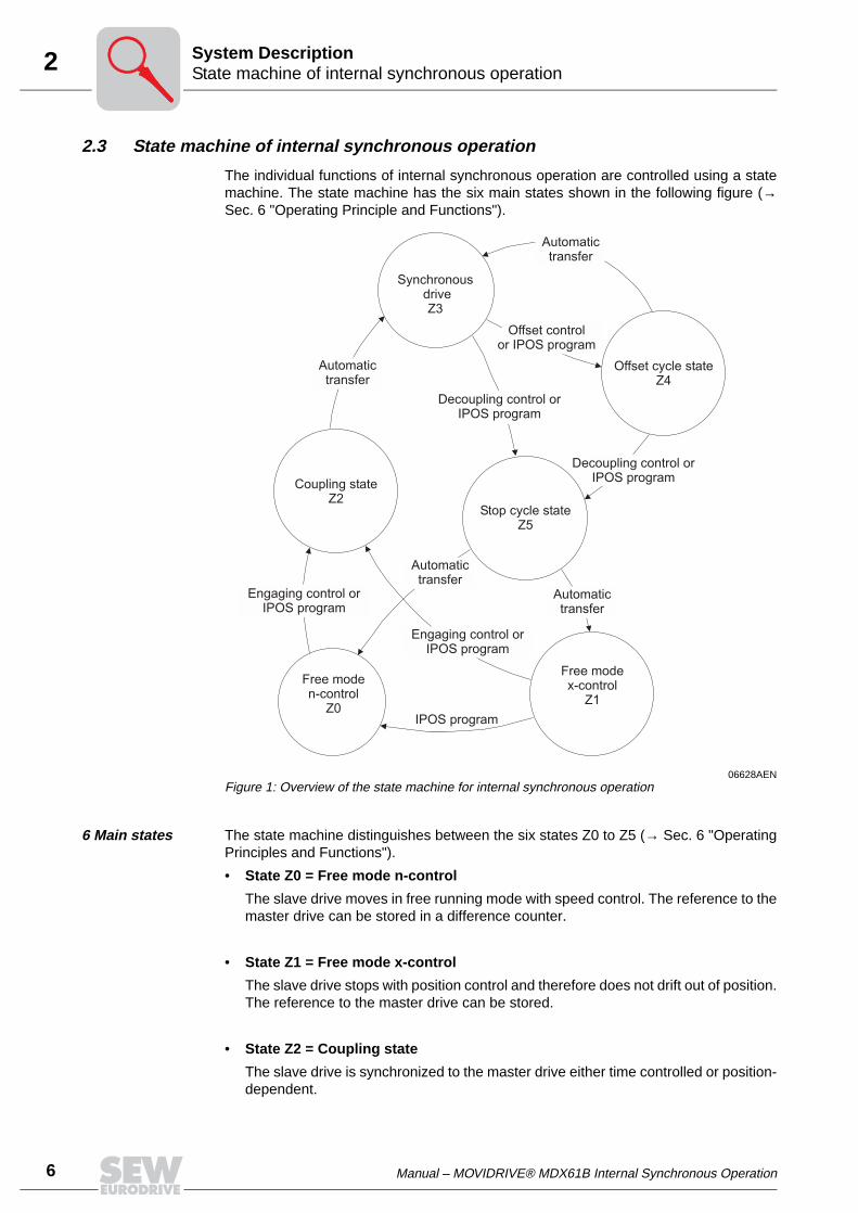
3 Project Planning3.1 Application examples
Master/slave mode of two drives
Master/slave mode of two drives with virtual encoder as master
06671AENFigure 2: Master/slave mode
X15X15
MDX61B...-5_3-4-0TBasic unit
X14 X14
Master Slave
Hip
erfa
ce
,R
esolv
er
Sin
/cos
encoder
®
Hip
erfa
ce
,R
esolv
er
Sin
/cos
encoder
®
06672AENFigure 3: Master/slave mode with virtual encoder
X15X15
MDX61B...-5_3-4-0TMDX61B...-5_3-4-0T
X14 X14
Master = virtual encoder Hip
erfa
ce
®,R
esolv
er
Sin
/cos
encoder
Hip
erfa
ce
®,R
esolv
er
Sin
/cos
encoder
Slave 1 Slave 2
IPOS-VariablesH370...
Manual – MOVIDRIVE® MDX61B Internal Synchronous Operation 9
3Application examplesProject Planning
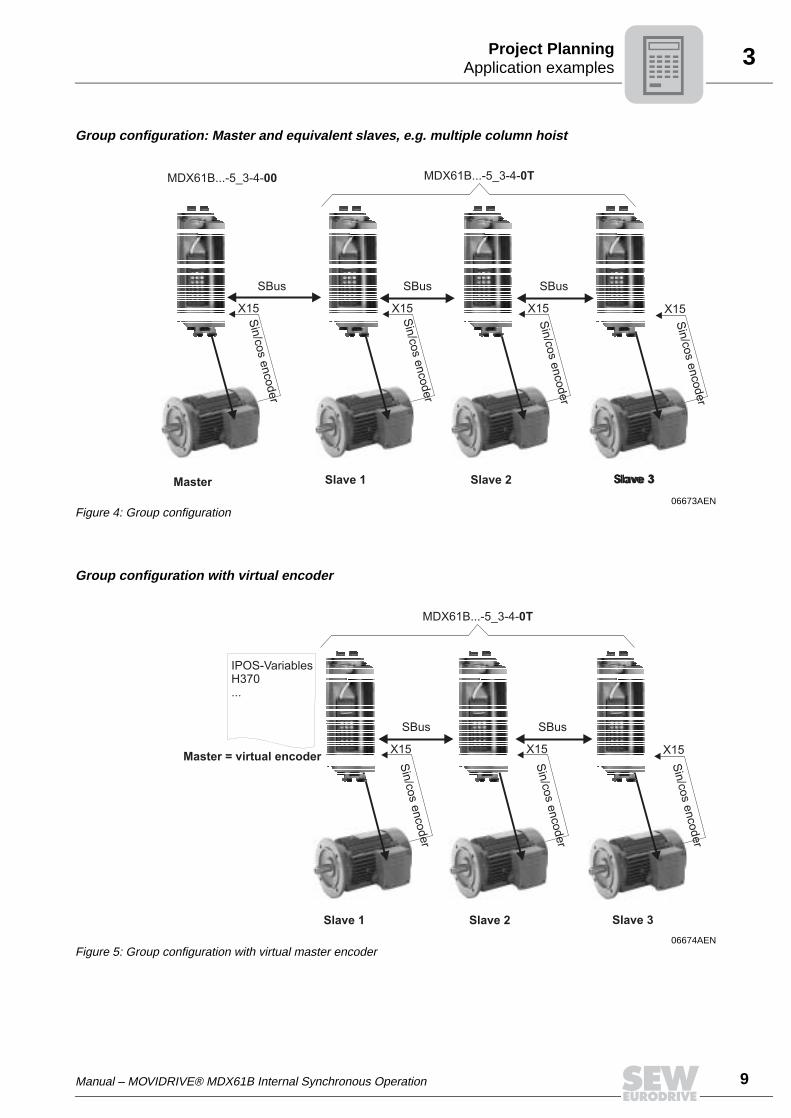
Group configuration: Master and equivalent slaves, e.g. multiple column hoist
Group configuration with virtual encoder
06673AENFigure 4: Group configuration
X15X15X15 X15
MDX61B...-5_3-4-0T
SBusSBus SBus
Slave 1 Slave 2 Slave 3
Sin
/cos
encoder
Sin
/cos
encoder
Sin
/cos
encoder
Sin
/cos
encoder
Master Slave 3
MDX61B...-5_3-4-00
06674AENFigure 5: Group configuration with virtual master encoder
X15X15 X15
MDX61B...-5_3-4-0T
SBus SBus
Slave 1 Slave 2 Slave 3
Sin
/cos
encoder
Sin
/cos
encoder
Sin
/cos
encoder
Master = virtual encoder
IPOS-VariablesH370...
10 Manual – MOVIDRIVE® MDX61B Internal Synchronous Operation
3 Application examplesProject Planning
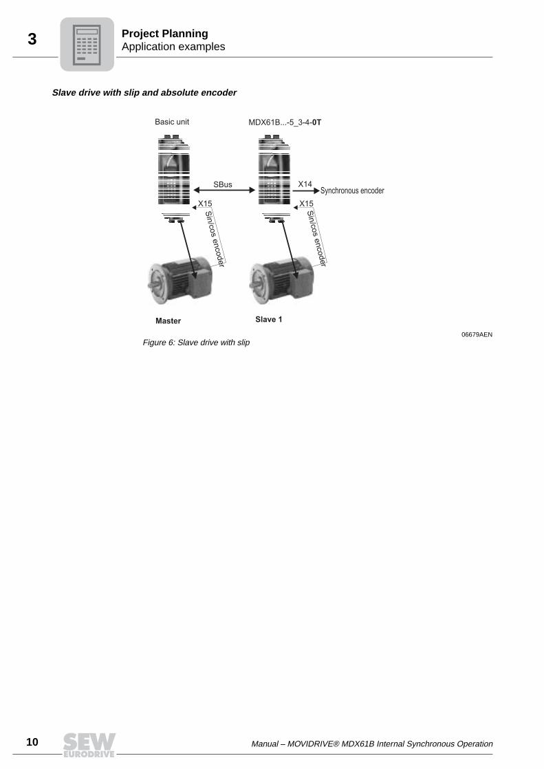
Slave drive with slip and absolute encoder
06679AENFigure 6: Slave drive with slip
X15X15
MDX61B...-5_3-4-0TBasic unit
X14Synchronous encoder
SBus
Slave 1
Sin
/cos
encoder
Sin
/cos
encoder
Master
Manual – MOVIDRIVE® MDX61B Internal Synchronous Operation 11
3RequirementsProject Planning
3.2 Requirements
PC and software You need the SEW MOVITOOLS® software package to be able to use internalsynchronous operation. To use MOVITOOLS®, you must have a PC with one of thefollowing operating systems: Windows® 95, Windows® 98, Windows NT® 4.0 orWindows® 2000.
IPOSplus® compiler
The application program for internal synchronous operation must be created using theIPOSplus® compiler. Do not use the assembler (on-screen programming) for thispurpose.
IPOSplus® variables H360 to H450 are defined for internal synchronous operation.
Inverter • The MOVIDRIVE® MDX61B...-5_3-4-0T application version already includes thetechnology function for internal synchronous operation.
• Internal synchronous operation has been implemented for MOVIDRIVE® MDX61Band places the following requirements on the drive system:
– Encoder feedback– "CFC", "SERVO" or "VFC-n control" operating modes with master/slave
connection via X14-X14
• Only parameter set 1 is available; parameter set 2 cannot be used.
• The DRS11 synchronous operation card is not supported and therefore may not beused.
Motors and encoders
• For operation on MOVIDRIVE® MDX61B:
– CT/CV asynchronous servomotor, high-resolution sin/cos encoder installed asstandard or HIPERFACE® encoder.
– AC motor DT/DV/D with incremental encoder option, preferably high-resolutionsin/cos encoder or HIPERFACE® encoder
– DS/CM synchronous servomotors, resolver (installed as standard) orHIPERFACE® encoder
High-resolution speed measurement is required for optimum operation of internalsynchronous operation. The encoders installed as standard on CT/CV and DS/CMmotors fulfill these requirements. If you use DT/DV/D motors, we recommend usingHIPERFACE® encoders or high-resolution sin/cos encoders ES1S, ES2S or EV1S.
Internal synchronous operation cannot be realized with
• MOVIDRIVE® MDX60B

12 Manual – MOVIDRIVE® MDX61B Internal Synchronous Operation
3 Project planning notesProject Planning
3.3 Project planning notes
• Do not use internal synchronous operation with systems that have a rigid mechanicalconnection.
• Equip slave inverters with a braking resistor.
• During project planning, bear in mind that the slave must be able to reduce the angledifferential between itself and the master to zero at any time. For this reason, set themaximum speed (P302) of the slave to a greater value than the maximum speed ofthe master by taking into account the scaling factors of master and slave.
• Provide for a sufficient torque reserve for the slave drive.
• During the time-controlled synchronization process, the synchronization speed of theslave drive must be faster than the maximum speed of the master drive.
• If possible, always use the same type of drives for internal synchronous operation.
• In the case of multiple column hoists, always use the same motors and the samegear units (identical ratios).
• When drives of the same type are operating as a synchronized group (e.g. multiplecolumn hoist), then the drive which carries the highest proportion of the load duringoperation must be selected as the master.
• Connect the slave motor encoder to terminal X15 (ENCODER IN) and the masterincremental encoder to terminal X14 (ENCODER IN/OUT) (→MOVIDRIVE®
MDX60B/61B operating instructions).
• Master is incremental encoder on terminal X14. Use an incremental encoder with themaximum possible resolution (max. 200 kHz).
• Operation with SBus → Setting up a cyclical data transfer in an IPOSplus® program:
– Group configuration: SBus connection between the master and all slave drives ispermitted
– SBus synchronization with transfer of the SBus synchronization ID– Transferring the position of the master drive
• Direct cable-break monitoring is possible for X14-X14 connection via theparameter encoder monitoring X14. Indirect cable-break monitoring is possibleduring operation with SBus by way of the SBus timeout response (P836).
Manual – MOVIDRIVE® MDX61B Internal Synchronous Operation 13
3Synchronous start / stopProject Planning
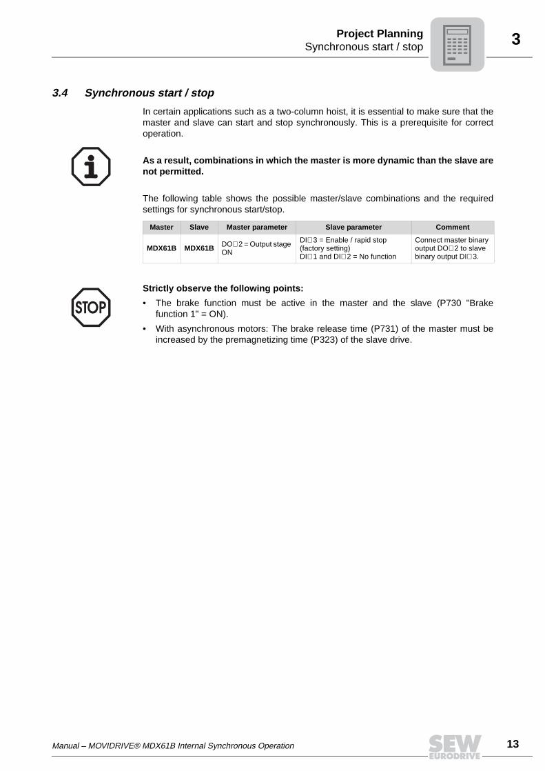
3.4 Synchronous start / stop
In certain applications such as a two-column hoist, it is essential to make sure that themaster and slave can start and stop synchronously. This is a prerequisite for correctoperation.
The following table shows the possible master/slave combinations and the requiredsettings for synchronous start/stop.
As a result, combinations in which the master is more dynamic than the slave arenot permitted.
Master Slave Master parameter Slave parameter Comment
MDX61B MDX61B DO∅ 2 = Output stage ON
DI∅ 3 = Enable / rapid stop (factory setting)DI∅ 1 and DI∅ 2 = No function
Connect master binary output DO∅ 2 to slave binary output DI∅ 3.
Strictly observe the following points:
• The brake function must be active in the master and the slave (P730 "Brakefunction 1" = ON).
• With asynchronous motors: The brake release time (P731) of the master must beincreased by the premagnetizing time (P323) of the slave drive.
14 Manual – MOVIDRIVE® MDX61B Internal Synchronous Operation
4 SoftwareInstallation
4 Installation4.1 Software
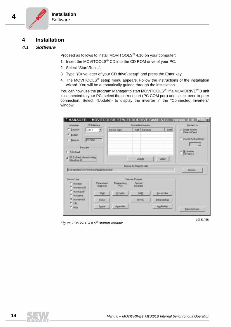
Proceed as follows to install MOVITOOLS® 4.10 on your computer:
1. Insert the MOVITOOLS® CD into the CD ROM drive of your PC.
2. Select "Start\Run...".
3. Type "Drive letter of your CD drive:setup" and press the Enter key.
4. The MOVITOOLS® setup menu appears. Follow the instructions of the installationwizard. You will be automatically guided through the installation.
You can now use the program Manager to start MOVITOOLS®. If a MOVIDRIVE® B unitis connected to your PC, select the correct port (PC COM port) and select peer-to-peerconnection. Select <Update> to display the inverter in the "Connected Inverters"window.
10383AENFigure 7: MOVITOOLS® startup window
Manual – MOVIDRIVE® MDX61B Internal Synchronous Operation 15
4Connection of encoder and resolverInstallation
4.2 Connection of encoder and resolver
General installation notes
• Max. line length of inverter - encoder/resolver: 100 m (330 ft) with a capacitance perunit length ≤ 120 nF/km (193 nF/mile).
• Core cross section: 0.20 ... 0.5 mm2 (AWG 24 ... 20)
• If you cut off a core of the encoder/resolver cable: Isolate the cut-off end of the core.
• Use shielded cables with twisted pairs of insulated conductors and connect the shieldat both ends
– to the encoder in the cable gland or in the encoder plug– to the inverter in the housing of the sub D plug
• Route the encoder/resolver cable separately from the power cables.
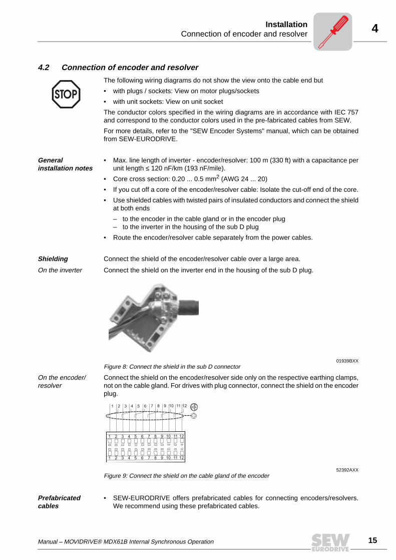
Shielding Connect the shield of the encoder/resolver cable over a large area.
On the inverter Connect the shield on the inverter end in the housing of the sub D plug.
On the encoder/resolver
Connect the shield on the encoder/resolver side only on the respective earthing clamps,not on the cable gland. For drives with plug connector, connect the shield on the encoderplug.
Prefabricated cables
• SEW-EURODRIVE offers prefabricated cables for connecting encoders/resolvers.We recommend using these prefabricated cables.
The following wiring diagrams do not show the view onto the cable end but
• with plugs / sockets: View on motor plugs/sockets
• with unit sockets: View on unit socket
The conductor colors specified in the wiring diagrams are in accordance with IEC 757and correspond to the conductor colors used in the pre-fabricated cables from SEW.
For more details, refer to the "SEW Encoder Systems" manual, which can be obtainedfrom SEW-EURODRIVE.
01939BXXFigure 8: Connect the shield in the sub D connector
52392AXXFigure 9: Connect the shield on the cable gland of the encoder
1 2 3 4 5 6 7 8 9 10
1 2 3 4 5 6 7 8 9 10
11 12
1 2 3 4 5 6 7 8 9 10 11 12
11 12
16 Manual – MOVIDRIVE® MDX61B Internal Synchronous Operation
4 Connecting incremental encoder master to MOVIDRIVE® slaveInstallation
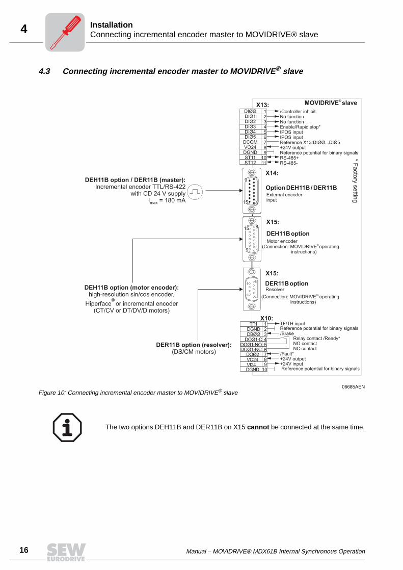
4.3 Connecting incremental encoder master to MOVIDRIVE® slave
06685AENFigure 10: Connecting incremental encoder master to MOVIDRIVE® slave
X13:
X14:
X15:
X15:
123456789
1011
Option DEH11B/DER11B
1
8
9
15
X10:TF1
DGNDDBØØ
DOØ1-CDOØ1-NODOØ1-NC
DOØ2VO24VI24DGND
123456789
10
TF/TH inputReference potential for binary signals/Brake
Relay contact /Ready*NO contactNC contact
/Fault*+24V output+24V inputReference potential for binary signals
DIØØDIØ1DIØ2DIØ3DIØ4DIØ5
DCOMVO24DGNDST11ST12
/Controller inhibitNo functionNo functionEnable/Rapid stop*IPOS inputIPOS inputReference X13:DIØØ...DIØ5+24V outputReference potential for binary signalsRS-485+RS-485-
MOVIDRIVE slave®
*F
acto
rysettin
g
External encoderinput
DEH11Boption
DER11Boption
Motor encoder
Resolver
(Connection: MOVIDRIVE operatinginstructions)
®
(Connection: MOVIDRIVE®)
operatinginstructions)
15
1
8
9
1
5
6
9DEH11B option (motor encoder):
high-resolution sin/cos encoder,
Hiperface or incremental encoder(CT/CV or DT/DV/D motors)
®
DER11B option (resolver):(DS/CM motors)
DEH11B option / DER11B (master):Incremental encoder TTL/RS-422
with CD 24 V supplyI = 180 mAmax
The two options DEH11B and DER11B on X15 cannot be connected at the same time.
Manual – MOVIDRIVE® MDX61B Internal Synchronous Operation 17
4Connecting incremental encoder master to MOVIDRIVE® slaveInstallation
Connecting HIP-ERFACE® encoder AV1H
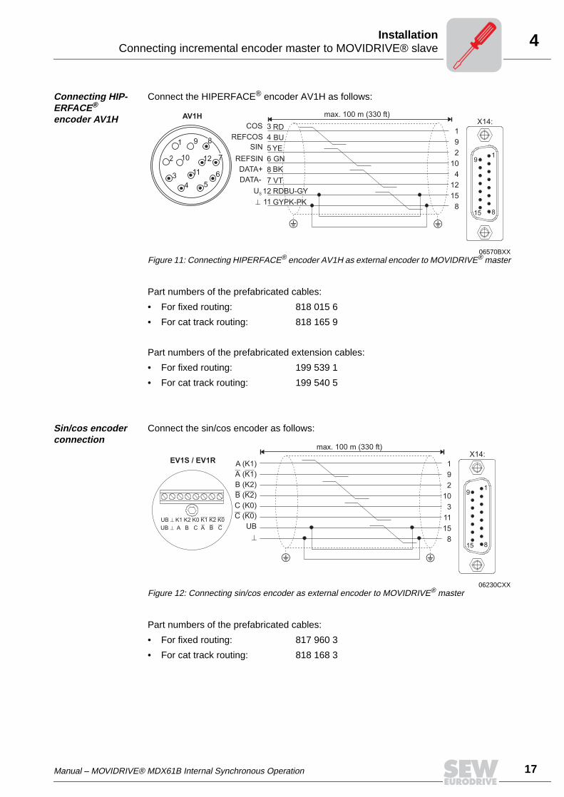
Connect the HIPERFACE® encoder AV1H as follows:
Part numbers of the prefabricated cables:
• For fixed routing: 818 015 6
• For cat track routing: 818 165 9
Part numbers of the prefabricated extension cables:
• For fixed routing: 199 539 1
• For cat track routing: 199 540 5
Sin/cos encoder connection
Connect the sin/cos encoder as follows:
Part numbers of the prefabricated cables:
• For fixed routing: 817 960 3
• For cat track routing: 818 168 3
06570BXXFigure 11: Connecting HIPERFACE® encoder AV1H as external encoder to MOVIDRIVE® master
X14:
1
8
9
15
1
9
2
10
4
12
15
8
max. 100 m (330 ft)
3
4
5
6
8
7
12
11
RD
BU
YE
GN
BK
VT
RDBU-GY
GYPK-PK
AV1H
3
4 5
6
9
10
11
12
1
2 7
8
COS
REFCOS
SIN
REFSIN
DATA+
DATA-
US
06230CXXFigure 12: Connecting sin/cos encoder as external encoder to MOVIDRIVE® master
EV1S / EV1R 1
9
2
10
3
11
15
8
X14:max. 100 m (330 ft)
1
8
9
15
18 Manual – MOVIDRIVE® MDX61B Internal Synchronous Operation
4 Connecting MOVIDRIVE® master to MOVIDRIVE® slaveInstallation
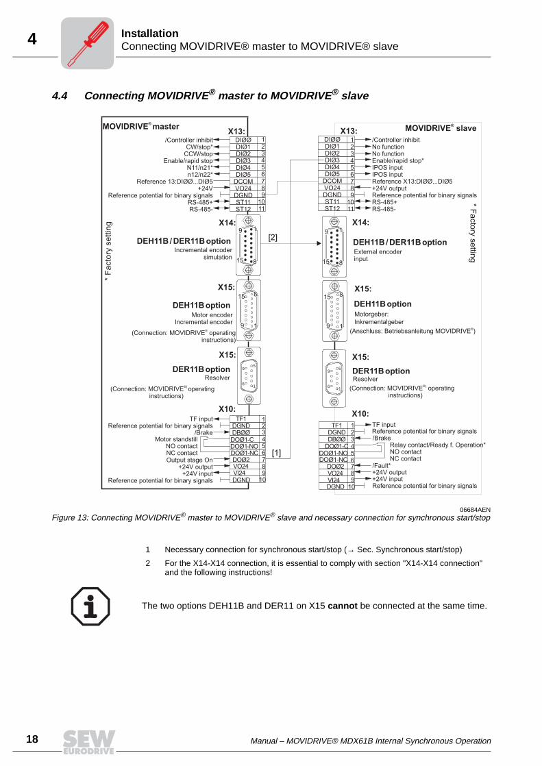
4.4 Connecting MOVIDRIVE® master to MOVIDRIVE® slave
06684AENFigure 13: Connecting MOVIDRIVE® master to MOVIDRIVE® slave and necessary connection for synchronous start/stop
X13:
X14:
X15:
X15:
X10:
123456789
1011
DEH11B/DER11Boption
X13:
X14:
X15:
X15:
X10:
1
8
9
15
1
8
9
15
TF1DGNDDBØØ
DOØ1-CDOØ1-NODOØ1-NC
DOØ2VO24VI24DGND
123456789
10
TF1DGNDDBØØDOØ1-CDOØ1-NODOØ1-NCDOØ2VO24VI24DGND
123456789
10
TF inputReference potential for binary signals/Brake
Relay contact/Ready f. Operation*NO contactNC contact
/Fault*+24V output+24V inputReference potential for binary signals
Reference potential for binary signals
Motor standstillNO contactNC contact
TF inputReference potential for binary signals
/Brake
Output stage On+24V output
+24V input
DIØØDIØ1DIØ2DIØ3DIØ4DIØ5
DCOMVO24DGNDST11ST12
DIØØDIØ1DIØ2DIØ3DIØ4DIØ5
DCOMVO24DGNDST11ST12
123456789
1011
*F
acto
rysettin
g
MOVIDRIVE master®
/Controller inhibitCW/stop*
CCW/stopEnable/rapid stop
N11/n21*n12/n22*
Reference 13:DIØØ...DIØ5+24V
Reference potential for binary signalsRS-485+RS-485-
/Controller inhibitNo functionNo functionEnable/rapid stop*IPOS inputIPOS inputReference X13:DIØØ...DIØ5+24V outputReference potential for binary signalsRS-485+RS-485-
MOVIDRIVE®
slave
*F
acto
rysettin
g
External encoderinput
DEH11B/DER11BoptionIncremental encoder
simulation
DEH11BoptionMotor encoder
Incremental encoder
(Connection: MOVIDRIVE operatinginstructions)
®
DEH11Boption
DER11BoptionDER11Boption
Motorgeber:
ResolverResolver
Inkrementalgeber
(Anschluss: Betriebsanleitung MOVIDRIVE )®
(Connection: MOVIDRIVE operatinginstructions)
®)
(Connection: MOVIDRIVE operatinginstructions)
®)
15
1
8
9
15
1
8
9
1
5
6
9
1
5
6
9
[1]
[2]
1 Necessary connection for synchronous start/stop (→ Sec. Synchronous start/stop)
2 For the X14-X14 connection, it is essential to comply with section "X14-X14 connection" and the following instructions!
The two options DEH11B and DER11 on X15 cannot be connected at the same time.
Manual – MOVIDRIVE® MDX61B Internal Synchronous Operation 19
4Connecting absolute encoder master to MOVIDRIVE® slaveInstallation
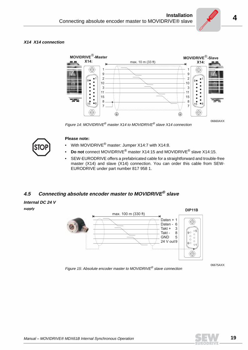
X14 X14 connection
4.5 Connecting absolute encoder master to MOVIDRIVE® slave
Internal DC 24 V supply
06660AXXFigure 14: MOVIDRIVE® master X14 to MOVIDRIVE® slave X14 connection
1
9
2
10
3
11
15
8
7
1
9
2
10
3
11
15
8
7
max. 10 m (33 ft)
1
8
9
15
1
8
9
15
Please note:
• With MOVIDRIVE® master: Jumper X14:7 with X14:8.
• Do not connect MOVIDRIVE® master X14:15 and MOVIDRIVE® slave X14:15.
• SEW-EURODRIVE offers a prefabricated cable for a straightforward and trouble-freemaster (X14) and slave (X14) connection. You can order this cable from SEW-EURODRIVE under part number 817 958 1.
06675AXXFigure 15: Absolute encoder master to MOVIDRIVE® slave connection
1
5
6
9
DIP11B
163859
Daten +Daten -Takt +Takt -GND24 V out
max. 100 m (330 ft)
20 Manual – MOVIDRIVE® MDX61B Internal Synchronous Operation
4 Connecting absolute encoder master to MOVIDRIVE® slaveInstallation
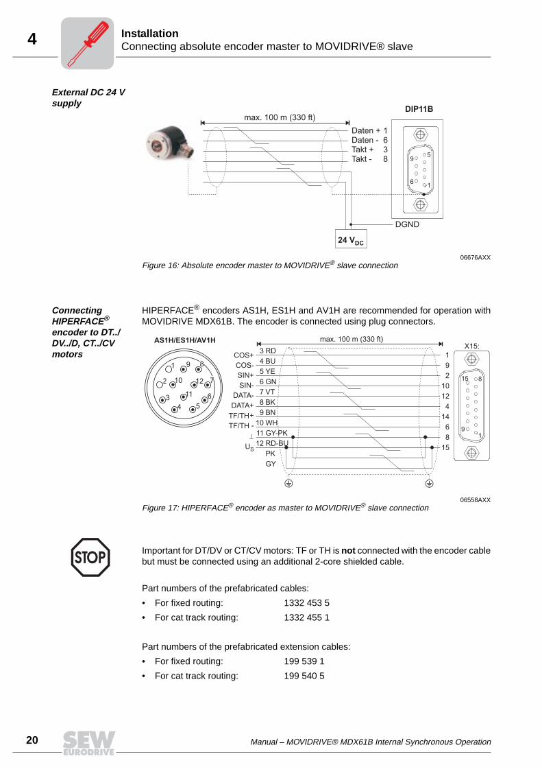
External DC 24 V supply
Connecting HIPERFACE® encoder to DT../DV../D, CT../CV motors
HIPERFACE® encoders AS1H, ES1H and AV1H are recommended for operation withMOVIDRIVE MDX61B. The encoder is connected using plug connectors.
Part numbers of the prefabricated cables:
• For fixed routing: 1332 453 5
• For cat track routing: 1332 455 1
Part numbers of the prefabricated extension cables:
• For fixed routing: 199 539 1
• For cat track routing: 199 540 5
06676AXXFigure 16: Absolute encoder master to MOVIDRIVE® slave connection
1
5
6
9
DIP11B
1638
24 VDC
DGND
Daten +Daten -Takt +Takt -
max. 100 m (330 ft)
06558AXXFigure 17: HIPERFACE® encoder as master to MOVIDRIVE® slave connection
1
9
2
10
12
4
14
6
8
15
1
8
9
15
X15:max. 100 m (330 ft)
3
4
5
6
7
8
9
10
11
12
RD
BU
YE
GN
VT
BK
BN
WH
GY-PK
RD-BU
PK
GY
AS1H/ES1H/AV1H
3
4 5
6
9
10
11
12
1
2 7
8
Important for DT/DV or CT/CV motors: TF or TH is not connected with the encoder cablebut must be connected using an additional 2-core shielded cable.
Manual – MOVIDRIVE® MDX61B Internal Synchronous Operation 21
4System bus connection of master/slaveInstallation
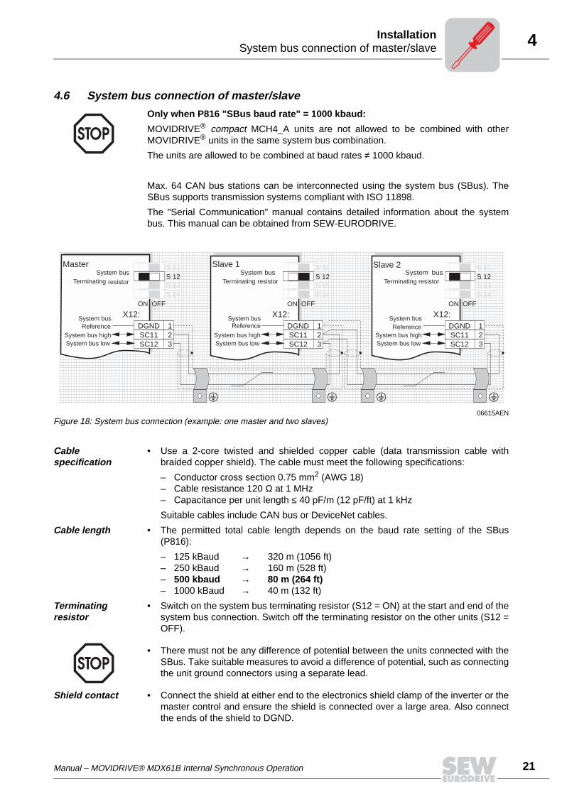
4.6 System bus connection of master/slave
Max. 64 CAN bus stations can be interconnected using the system bus (SBus). TheSBus supports transmission systems compliant with ISO 11898.
The "Serial Communication" manual contains detailed information about the systembus. This manual can be obtained from SEW-EURODRIVE.
Cable specification
• Use a 2-core twisted and shielded copper cable (data transmission cable withbraided copper shield). The cable must meet the following specifications:
– Conductor cross section 0.75 mm2 (AWG 18)– Cable resistance 120 Ω at 1 MHz– Capacitance per unit length ≤ 40 pF/m (12 pF/ft) at 1 kHz
Suitable cables include CAN bus or DeviceNet cables.
Cable length • The permitted total cable length depends on the baud rate setting of the SBus(P816):
– 125 kBaud → 320 m (1056 ft)– 250 kBaud → 160 m (528 ft)– 500 kbaud → 80 m (264 ft)– 1000 kBaud → 40 m (132 ft)
Terminating resistor
• Switch on the system bus terminating resistor (S12 = ON) at the start and end of thesystem bus connection. Switch off the terminating resistor on the other units (S12 =OFF).
Shield contact • Connect the shield at either end to the electronics shield clamp of the inverter or themaster control and ensure the shield is connected over a large area. Also connectthe ends of the shield to DGND.
Only when P816 "SBus baud rate" = 1000 kbaud:
MOVIDRIVE® compact MCH4_A units are not allowed to be combined with otherMOVIDRIVE® units in the same system bus combination.
The units are allowed to be combined at baud rates ≠ 1000 kbaud.
06615AENFigure 18: System bus connection (example: one master and two slaves)
X12:DGNDSC11SC12
123
S 12S 11
S 13S 14
ON OFF
X12:DGNDSC11SC12
123
S 12S 11
S 13S 14
ON OFF
X12:DGNDSC11SC12
123
S 11
S 13S 14
S 12
ON OFF
Master Slave 1 Slave 2
System busReference
System busReference
System busReference
System bus high System bus high System bus highSystem bus low System bus low System bus low
System busTerminating resistor
System busTerminating resistor
System busTerminating resistor
• There must not be any difference of potential between the units connected with theSBus. Take suitable measures to avoid a difference of potential, such as connectingthe unit ground connectors using a separate lead.
22 Manual – MOVIDRIVE® MDX61B Internal Synchronous Operation
5 Controlling internal synchronous operationOperating principle and functions
5 Operating principle and functions5.1 Controlling internal synchronous operation
Internal synchronous operation is controlled using IPOSplus® variables within theIPOSplus® program, in the following referred to as "application." All states of internalsynchronous operation can be viewed and set in a variable range from H360 to H450which is reserved for internal synchronous operation (→ Sec. "System variables"). Allvariables that are connected to internal synchronous operation have symbolic names.These variables are shown below in bold and italics.
5.2 Main state machine
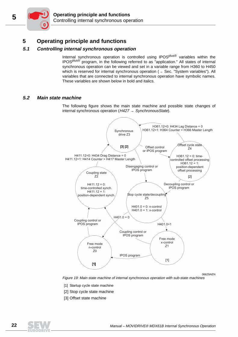
The following figure shows the main state machine and possible state changes ofinternal synchronous operation (H427 → SynchronousState).
06629AENFigure 19: Main state machine of internal synchronous operation with sub-state machines
[1] Startup cycle state machine
[2] Stop cycle state machine
[3] Offset state machine
[3] [2][3] [2]
[1][1][1][1][1]
[1]
[2]
Free moden-control
Z0
Synchronousdrive Z3
Free modex-control
Z1
Coupling stateZ2
H411.12 = 0:time-controlled synch.
H411.12 = 1:position-dependent synch.
Coupling control orIPOS program
Stop cycle state/decouplingZ5
H401.0 = 0: n-controlH401.0 = 1: x-control
Offset cycle stateZ4
H361.12 = 0: time-controlled offset processing
H361.12 = 1:position-dependentoffset processing
Coupling control orIPOS program
H411.12=0: H434 Drag Distance = 0H411.12=1: H414 Counter > H417 Master Length
Disengaging control orIPOS program
H401.0 = 0
H401.0=1
IPOS program
Decoupling control orIPOS program
H361.12=0: H434 Lag Distance = 0H361.12=1: H364 Counter > H366 Master Length
Offset controlor IPOS program
00
I
Manual – MOVIDRIVE® MDX61B Internal Synchronous Operation 23
5Main state machineOperating principle and functions
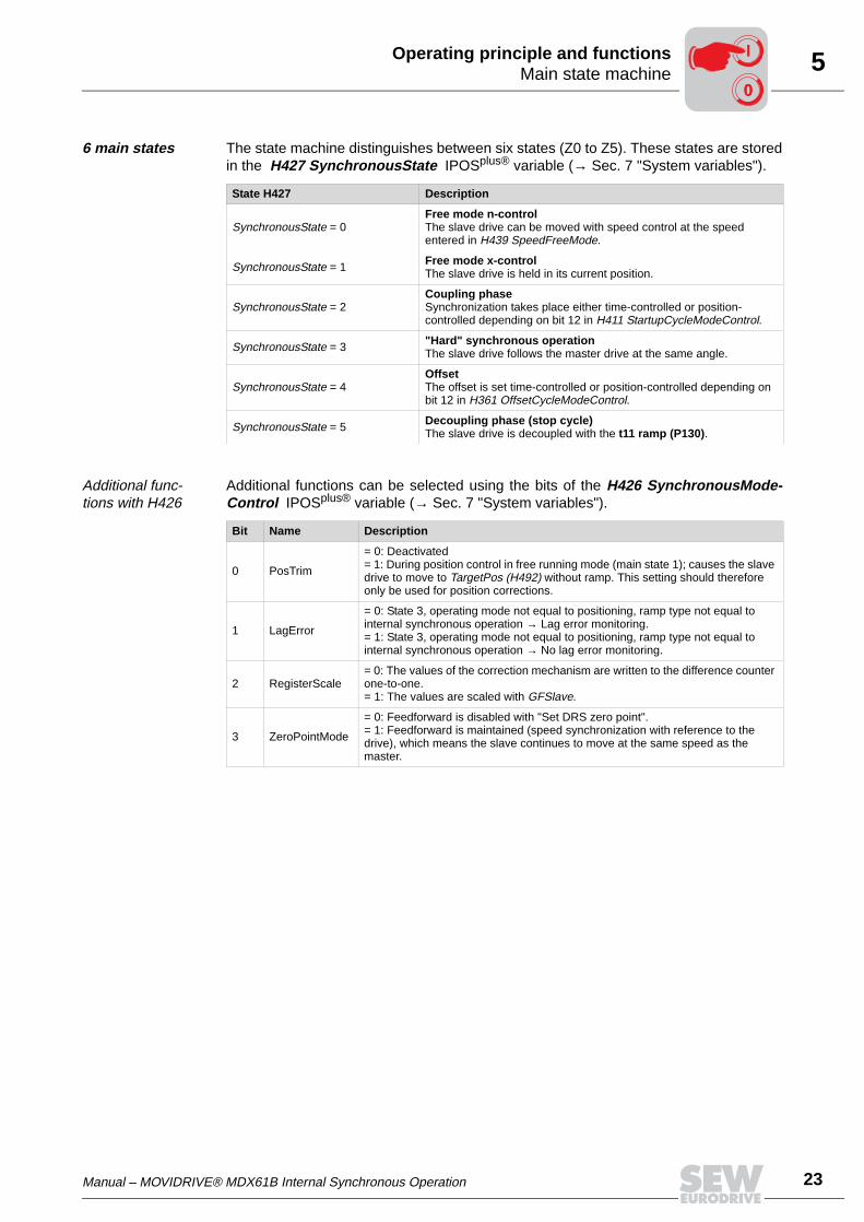
6 main states The state machine distinguishes between six states (Z0 to Z5). These states are storedin the H427 SynchronousState IPOSplus® variable (→ Sec. 7 "System variables").
Additional func-tions with H426
Additional functions can be selected using the bits of the H426 SynchronousMode-Control IPOSplus® variable (→ Sec. 7 "System variables").
State H427 Description
SynchronousState = 0Free mode n-controlThe slave drive can be moved with speed control at the speed entered in H439 SpeedFreeMode.
SynchronousState = 1 Free mode x-controlThe slave drive is held in its current position.
SynchronousState = 2Coupling phaseSynchronization takes place either time-controlled or position-controlled depending on bit 12 in H411 StartupCycleModeControl.
SynchronousState = 3 "Hard" synchronous operationThe slave drive follows the master drive at the same angle.
SynchronousState = 4OffsetThe offset is set time-controlled or position-controlled depending on bit 12 in H361 OffsetCycleModeControl.
SynchronousState = 5 Decoupling phase (stop cycle)The slave drive is decoupled with the t11 ramp (P130).
Bit Name Description
0 PosTrim
= 0: Deactivated= 1: During position control in free running mode (main state 1); causes the slave drive to move to TargetPos (H492) without ramp. This setting should therefore only be used for position corrections.
1 LagError
= 0: State 3, operating mode not equal to positioning, ramp type not equal to internal synchronous operation → Lag error monitoring.= 1: State 3, operating mode not equal to positioning, ramp type not equal to internal synchronous operation → No lag error monitoring.
2 RegisterScale= 0: The values of the correction mechanism are written to the difference counter one-to-one.= 1: The values are scaled with GFSlave.
3 ZeroPointMode
= 0: Feedforward is disabled with "Set DRS zero point".= 1: Feedforward is maintained (speed synchronization with reference to the drive), which means the slave continues to move at the same speed as the master.
00
I
24 Manual – MOVIDRIVE® MDX61B Internal Synchronous Operation
5 Startup cycle mode controlOperating principle and functions
5.3 Startup cycle mode control
Time-controlled synchronization process
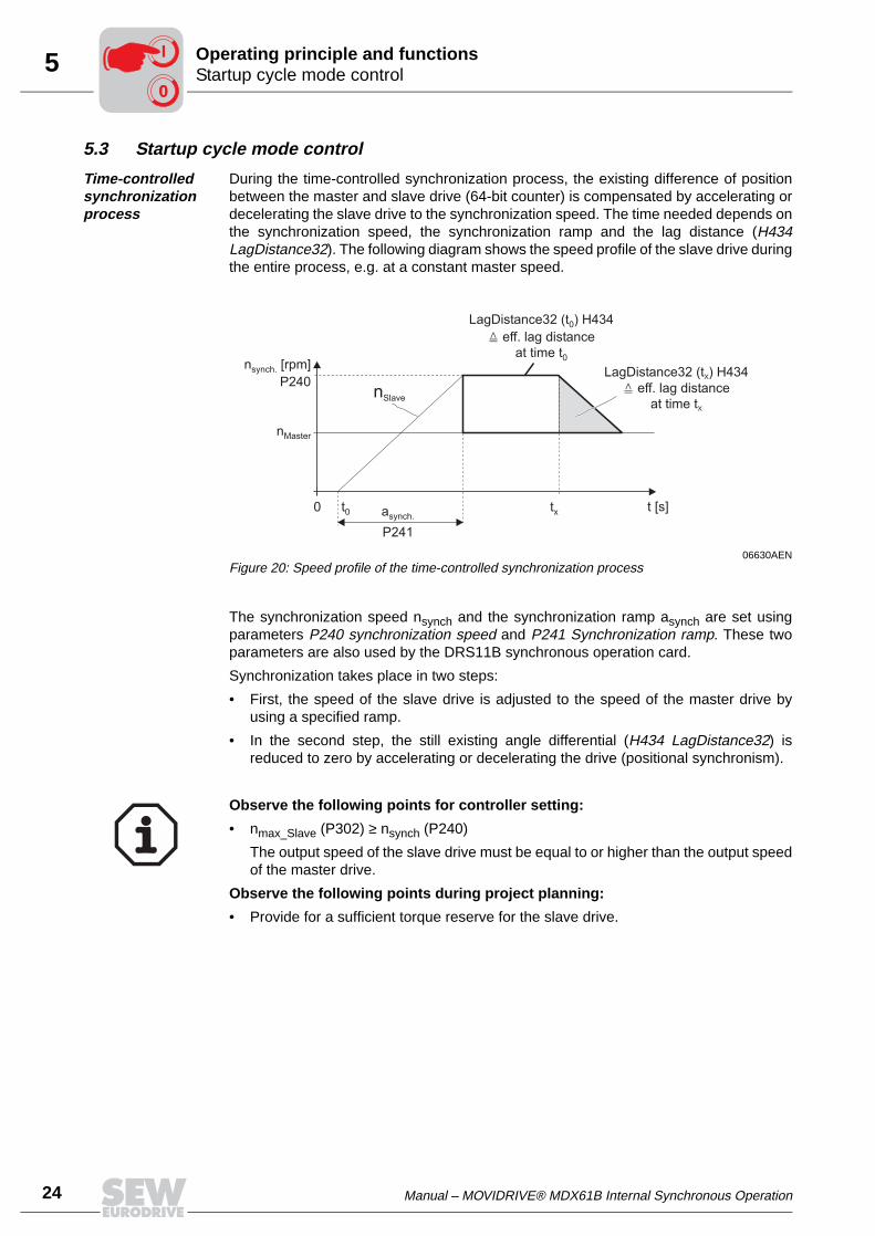
During the time-controlled synchronization process, the existing difference of positionbetween the master and slave drive (64-bit counter) is compensated by accelerating ordecelerating the slave drive to the synchronization speed. The time needed depends onthe synchronization speed, the synchronization ramp and the lag distance (H434LagDistance32). The following diagram shows the speed profile of the slave drive duringthe entire process, e.g. at a constant master speed.
The synchronization speed nsynch and the synchronization ramp asynch are set usingparameters P240 synchronization speed and P241 Synchronization ramp. These twoparameters are also used by the DRS11B synchronous operation card.
Synchronization takes place in two steps:
• First, the speed of the slave drive is adjusted to the speed of the master drive byusing a specified ramp.
• In the second step, the still existing angle differential (H434 LagDistance32) isreduced to zero by accelerating or decelerating the drive (positional synchronism).
06630AENFigure 20: Speed profile of the time-controlled synchronization process
nMaster
t [s]
nSlave
0 txasynch.
P241
t0
nsynch. [rpm]
P240LagDistance32 ( ) H434
eff. lag distance
at time t
X
tX
LagDistance32 ( ) H434
eff. lag distance
at time t
0
t0
Observe the following points for controller setting:
• nmax_Slave (P302) ≥ nsynch (P240)
The output speed of the slave drive must be equal to or higher than the output speedof the master drive.
Observe the following points during project planning:
• Provide for a sufficient torque reserve for the slave drive.
00
I
Manual – MOVIDRIVE® MDX61B Internal Synchronous Operation 25
5Startup cycle mode controlOperating principle and functions
Position-depen-dent synchroni-zation process
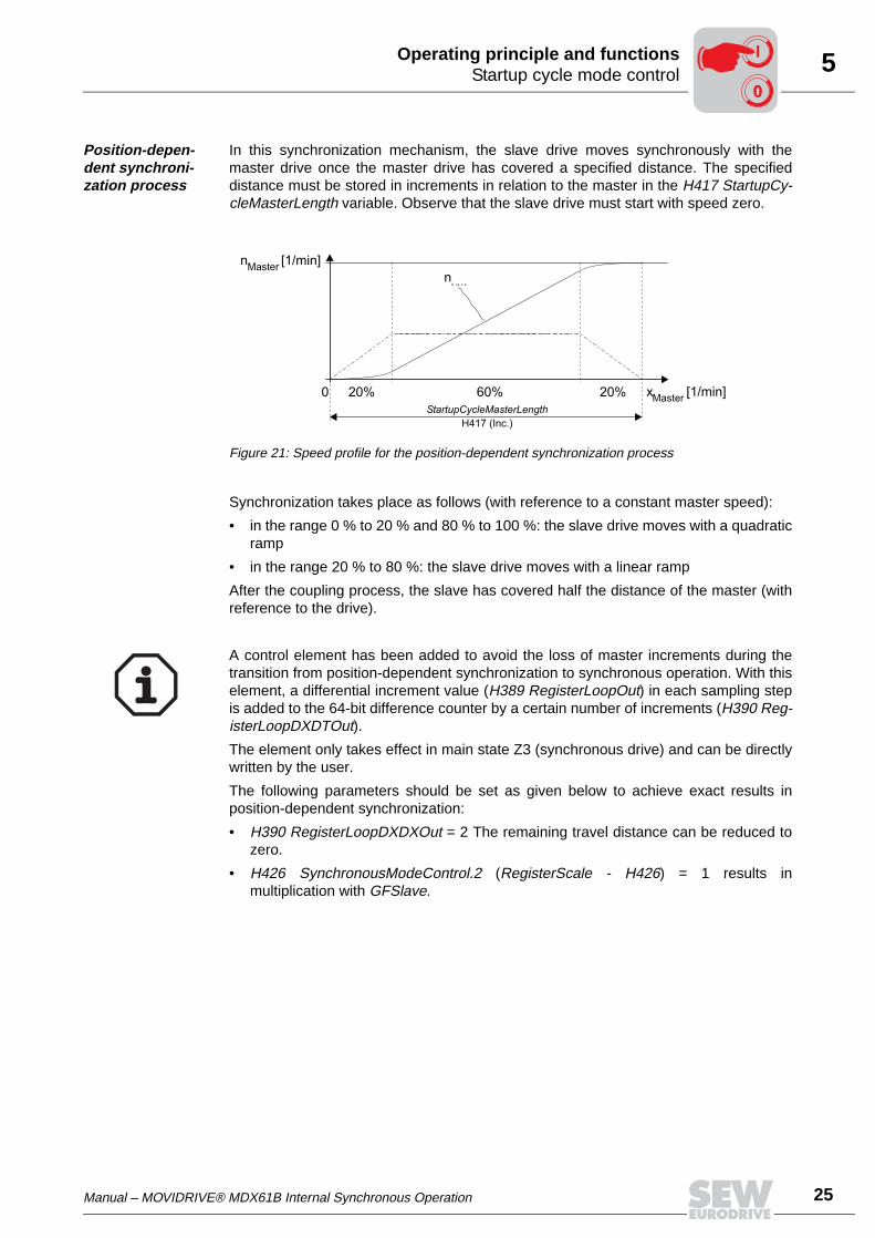
In this synchronization mechanism, the slave drive moves synchronously with themaster drive once the master drive has covered a specified distance. The specifieddistance must be stored in increments in relation to the master in the H417 StartupCy-cleMasterLength variable. Observe that the slave drive must start with speed zero.
Synchronization takes place as follows (with reference to a constant master speed):
• in the range 0 % to 20 % and 80 % to 100 %: the slave drive moves with a quadraticramp
• in the range 20 % to 80 %: the slave drive moves with a linear ramp
After the coupling process, the slave has covered half the distance of the master (withreference to the drive).
Figure 21: Speed profile for the position-dependent synchronization process
A control element has been added to avoid the loss of master increments during thetransition from position-dependent synchronization to synchronous operation. With thiselement, a differential increment value (H389 RegisterLoopOut) in each sampling stepis added to the 64-bit difference counter by a certain number of increments (H390 Reg-isterLoopDXDTOut).
The element only takes effect in main state Z3 (synchronous drive) and can be directlywritten by the user.
The following parameters should be set as given below to achieve exact results inposition-dependent synchronization:
• H390 RegisterLoopDXDXOut = 2 The remaining travel distance can be reduced tozero.
• H426 SynchronousModeControl.2 (RegisterScale - H426) = 1 results inmultiplication with GFSlave.
00
I
26 Manual – MOVIDRIVE® MDX61B Internal Synchronous Operation
5 Startup cycle mode controlOperating principle and functions
Startup cycle state machine
Startup cycle mode control reacts in the main states Z0 and Z1. The startup cycleprocess of the slave to the master can be performed either manually, event-driven orwith interrupt control.
The startup cycle mode is defined with the H410 StartupCycleMode system variable.Additional functions can be programmed with the H411 StartupCycleModeControlsystem variable.
System variable H410 StartupCycleMode → coupling mode:
• Manual coupling (StartupCycleMode = 0)
The coupling process starts when the application assigns the value 2 to the H427SynchronousState system variable.
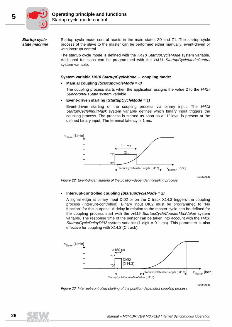
• Event-driven starting (StartupCycleMode = 1)
Event-driven starting of the coupling process via binary input. The H413StartupCycleInputMask system variable defines which binary input triggers thecoupling process. The process is started as soon as a "1" level is present at thedefined binary input. The terminal latency is 1 ms.
• Interrupt-controlled coupling (StartupCycleMode = 2)
A signal edge at binary input DI02 or on the C track X14:3 triggers the couplingprocess (interrupt-controlled). Binary input DI02 must be programmed to "Nofunction" for this purpose. A delay in relation to the master cycle can be defined forthe coupling process start with the H415 StartupCycleCounterMaxValue systemvariable. The response time of the sensor can be taken into account with the H416StartupCycleDelayDI02 system variable (1 digit = 0.1 ms). This parameter is alsoeffective for coupling with X14:3 (C track).
06632AENFigure 22: Event-driven starting of the position-dependent coupling process
06633AENFigure 23: Interrupt-controlled starting of the position-dependent coupling process
n [1/min]Slave
x [Incr.]Master
"1"
"0"
DI..
StartupCycleMasterLength (H417)
1 ms
n [1/min]Slave
x [Incr.]Master
"1"
"0"
DIØ2(X14:3)
StartupCycleCounterMaxValue (H415)
StartupCycleMasterLength (H417)
150 µs
00
I

Manual – MOVIDRIVE® MDX61B Internal Synchronous Operation 27
5Startup cycle mode controlOperating principle and functions
Startup cycle state machine in H412 StartupCycleState:
Application example
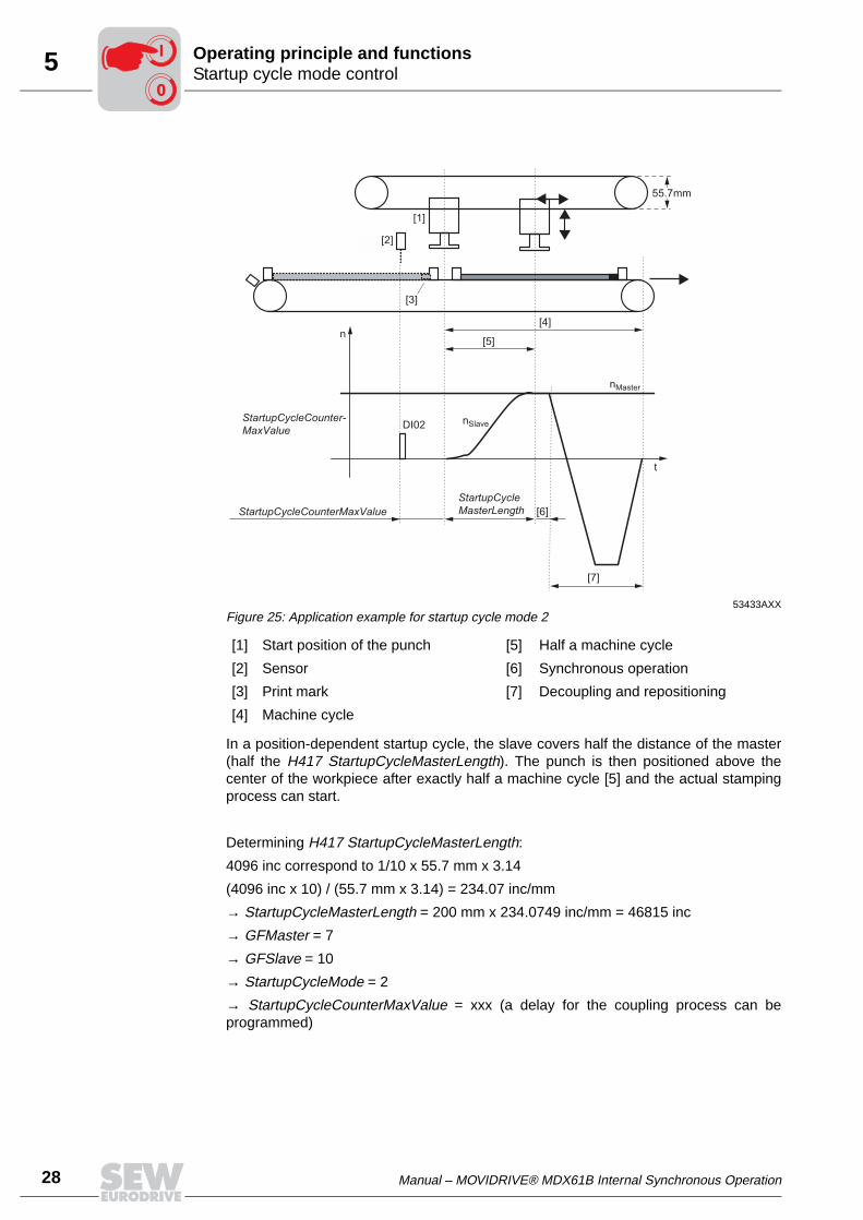
Figure 25 shows the following application example for coupling mode 2:
The center of a moving workpiece is to be stamped by a punch. The presence of aworkpiece and the starting time for synchronization are determined by a sensor [2],which scans a print mark [3] on the workpiece. Synchronizing, stamping andrepositioning [7] are to be performed within one machine cycle [4].
Mechanical structure:
iMaster = 10
iSlave = 7
dMaster = dSlave = 55.7 mm
Length of a machine cycle = 200 mm
06634AENFigure 24: Startup cycle state machine with interrupt control (startup cycle mode 2)
Interruptdeactivated
(EZ0)
Delay(EZ3)
Coupling andresetting of
engaging counterH414=H414-H415
(EZ4)
Interrupt isenabled(EZ1)
Waiting onInterrupt
(EZ2)
automatic
IPOS program
AutoRestartdeactivated
IPOS program
H414>=H415
AutoRestart
Interrupt andH415!=0
Interrupt andH415==0
00
I
28 Manual – MOVIDRIVE® MDX61B Internal Synchronous Operation
5 Startup cycle mode controlOperating principle and functions
In a position-dependent startup cycle, the slave covers half the distance of the master(half the H417 StartupCycleMasterLength). The punch is then positioned above thecenter of the workpiece after exactly half a machine cycle [5] and the actual stampingprocess can start.
Determining H417 StartupCycleMasterLength:
4096 inc correspond to 1/10 x 55.7 mm x 3.14
(4096 inc x 10) / (55.7 mm x 3.14) = 234.07 inc/mm
→ StartupCycleMasterLength = 200 mm x 234.0749 inc/mm = 46815 inc
→ GFMaster = 7
→ GFSlave = 10
→ StartupCycleMode = 2
→ StartupCycleCounterMaxValue = xxx (a delay for the coupling process can beprogrammed)
53433AXXFigure 25: Application example for startup cycle mode 2
[1] Start position of the punch [5] Half a machine cycle
[2] Sensor [6] Synchronous operation
[3] Print mark [7] Decoupling and repositioning
[4] Machine cycle
55.7mm
[1]
[2]
[4]
[3]
[5]
t
n
StartupCycleCounter-
MaxValue
StartupCycleCounterMaxValue
StartupCycle
MasterLength
DI02 nSlave
nMaster
[6]
[7]
00
I

Manual – MOVIDRIVE® MDX61B Internal Synchronous Operation 29
5Startup cycle mode controlOperating principle and functions
• Position-controlled coupling (StartupCycleMode = 3)
The coupling process is initiated by the H414 StartupCycleCounter position counter.Coupling takes place automatically if the StartupCycleCounter value is greater thanthe H415 StartupCycleCounterMaxValue counter overrun value. In this case,StartupCycleCounterMaxValue must be greater than the total number of inputmaster encoder pulses in the startup cycle, master cycle and stop cycle.
Startup cycle state machine in H412 StartupCycleState:
H411 StartupCycleModeControl system variable → Additional functions:
06635AENFigure 26: Position-controlled starting of the position-dependent coupling process
[1] Synchronous drive and and stop cycle time
[2] Slave is decoupled, time for repositioning to the initial position
06636AENFigure 27: Startup cycle state machine with position control (startup cycle mode 3)
Bit Name Description
0 AutoRestartModes 2 and 3
= 0: AutoRestart deactivated.= 1: AutoRestart.
1 StartupDisableModes 2 and 3
= 0: Coupling possible= 1: Coupling disabled
2 InterruptSelectMode 2
= 0: DI02.= 1: X14 C track
12 StartupMode = 0: Time-controlled synchronization means the existing difference of master and slave positions is eliminated by accelerating the slave drive to the synchroni-zation speed (P240 synchronization speed) and the synchronization ramp (P241 synchronization ramp).= 1: Position-dependent synchronization process means the slave moves synchronously to the master as soon as the master has covered the distance specified in StartupCycleMasterLength. Important: The starting speed of the slave must be zero!
nSlave [1/min]
xMaster [Incr.]
StartupCycleCounterMaxValue (H415)
StartupCycleCounter (H414)
2.StartupCycleMasterLength (H417) 1.
deactivated(EZ0)
Countercontrol(EZ1)
H414 H415
Coupling andresetting of
engaging counterH414=H414-H415
IPOS program
AutoRestartdeactivated
AutoRestart
00
I

30 Manual – MOVIDRIVE® MDX61B Internal Synchronous Operation
5 Synchronous operationOperating principle and functions
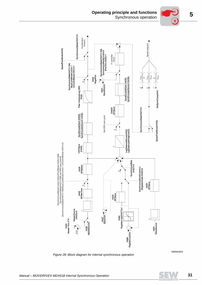
5.4 Synchronous operation
Control takes place with a P-controller. The master and slave pulses are evaluated withthe corresponding scaling factors and added up to a 64-bit value after comparison. TheP-controller together with the feedforward and subsequent limiting to the maximumspeed provide the speed setpoint for the speed controller.
A control element has been added to avoid the loss of master increments during thetransition from position-dependent synchronization to synchronous operation. With thiselement, a certain difference of increments (H389 RegisterLoopOut) in each samplingstep is added to the 64-bit difference counter by a certain number of increments (H390RegisterLoopDXDTOut). The element only takes effect in main state Z3 (synchronousdrive) and can be directly written by the user.
00
I
Manual – MOVIDRIVE® MDX61B Internal Synchronous Operation 31
5Synchronous operationOperating principle and functions
06694AENFigure 28: Block diagram for internal synchronous operation
H4
42
Ma
ste
rT
rim
X1
4
X1
4M
aste
rSo
urc
e(H
43
0)=
0
H4
30
Ma
ste
rSo
urc
e
+ +1
H4
46
MF
ilte
rTim
eH
42
8G
FM
aste
r
1/G
FS
lave
(H4
29
)S
yn
cE
nco
de
rNu
m(H
43
5)
Syn
cE
nco
de
rDe
no
m(H
43
6)
H4
37
Sla
ve
Trim
H3
89
Re
gis
terL
oo
pO
ut
+-
++
Syn
ch
ron
ou
sS
tate
H4
27
)=1
&&
Sto
pC
ycle
Mo
de
Co
ntr
ol.1
(XC
on
tro
lMo
de
-H4
01
)=1
Sp
ee
dF
ree
Mo
de
(H4
39
)
Syn
ch
ron
ou
sS
tate
(H4
27
)=0
+
+
+-
H3
90
Re
gis
terL
oo
pD
XD
TO
ut
H4
29
GF
Sla
ve
0
Syn
ch
ron
ou
sS
tate
(H4
27
)=3
Syn
ch
ron
ou
sM
od
eC
on
tro
l.2
(Re
gis
terS
ca
le-H
42
6)=
0
1
H4
31
Sla
ve
So
urc
e
H4
29
GF
Sla
ve
0
La
gD
ista
nce
64
Lo
w(H
43
2)
La
gD
ista
nce
64
Hig
h(H
43
3)
11
/H4
29
GF
Sla
ve
Syn
cE
nco
de
rNu
m(H
43
5)
Syn
cE
nco
de
rDe
no
m(H
43
6)
+ -
H4
31
Sla
ve
So
urc
e
H4
92
Ta
rge
tPo
s Syn
ch
ron
ou
sS
tate
(H4
27
)=1
&&
Syn
ch
ron
ou
sM
od
eC
on
tro
l.0
(Po
sT
rim
-H4
26
)=1
nm
ax
nm
ax
-nm
ax
-nm
ax
0
0 0
2 1
Re
Sp
rin
tClo
se
(44
4)
Syn
ch
ron
ou
sS
tate
(H4
27
)=0
Sp
ee
dF
ree
Mo
de
(H4
39
)
+-
00
Filt
er
Vo
rste
ue
run
gD
RS
P2
28
H4
42
Ma
ste
rT
rim
X1
4
Ma
ste
rSo
urc
e(H
43
0)=
0
H4
30
Ma
ste
rSo
urc
e
H4
46
MF
ilte
rTim
eH
42
8G
FM
aste
r
1/G
FS
lave
(H4
29
)S
yn
cE
nco
de
rNu
m(H
43
5)
Syn
cE
nco
de
rDe
no
m(H
43
6)
H4
37
Sla
ve
Trim
H3
89
Re
gis
terL
oo
pO
ut
Syn
ch
ron
ou
sS
tate
H4
27
)=1
&&
Sto
pC
ycle
Mo
de
Co
ntr
ol.1
(XC
on
tro
lMo
de
-H4
01
)=1
Sp
ee
dF
ree
Mo
de
(H4
39
)
Syn
ch
ron
ou
sS
tate
(H4
27
)=0
H3
90
Re
gis
terL
oo
pD
XD
TO
ut
H4
29
GF
Sla
ve
Syn
ch
ron
ou
sS
tate
(H4
27
)=3
Syn
ch
ron
ou
sM
od
eC
on
tro
l.2
(Re
gis
terS
ca
le-H
42
6)=
0
H4
31
Sla
ve
So
urc
e
H4
29
GF
Sla
ve
La
gD
ista
nce
64
Lo
w(H
43
2)
La
gD
ista
nce
64
Hig
h(H
43
3)
1/H
42
9G
FS
lave
Syn
cE
nco
de
rNu
m(H
43
5)
Syn
cE
nco
de
rDe
no
m(H
43
6)
H4
31
Sla
ve
So
urc
e
H4
92
Ta
rge
tPo
s Syn
ch
ron
ou
sS
tate
(H4
27
)=1
&&
Syn
ch
ron
ou
sM
od
eC
on
tro
l.0
(Po
sT
rim
-H4
26
)=1
Re
Sp
rin
tClo
se
(44
4)
Syn
ch
ron
ou
sS
tate
(H4
27
)=0
Sp
ee
dF
ree
Mo
de
(H4
39
)
Filt
er
Vo
rste
ue
run
gD
RS
P2
28
(Syn
ch
ron
ou
sM
od
eC
on
tro
l.3
(Ze
roP
oin
tMo
de
-H4
26
)=0
&&
Syn
ch
ron
ou
sS
tate
(H4
27
)=3
&&
se
tD
RS
ze
rop
oin
t)II
(Syn
ch
ron
ou
sS
tate
(H4
27
)=1
&&
Sto
pC
ycle
Mo
de
Co
ntr
ol.1
(XC
on
tro
lMo
de
-H4
01
)=0
)
Acce
lera
tio
nfo
rwa
rd
Se
tD
RS
ze
rop
oin
t
Xco
ntr
olle
rP
91
0
Sp
ee
dse
tpo
int
00
I
32 Manual – MOVIDRIVE® MDX61B Internal Synchronous Operation
5 Synchronous operationOperating principle and functions
Correcting func-tion (Register-Scale / Register-Loop)
A correction value can be entered via H389 RegisterLoopOut, which is added by thedifference counter. To avoid speed step changes, this correction value is not added atonce but is limited by the value H390 RegisterLoopDXDTOut (resolution in inc/ms).
Example A correction value of 10000 inc is to be added to the difference counter within 500 ms:
• 10000 inc / 500 ms = 20 inc/ms
• H389 RegisterLoopOut = 10000
• H390 RegisterLoopDXDTOut = 20
In this case, the correction value of 10000 inc is reduced at 20 inc/ms, which means thecorrection lasts 500 ms.
Please note:
• A value must be written to the limitation H390 RegisterLoopDXDTOut. If no value iswritten, a correction factor entered in H389 RegisterLoopOut will become invalid. Themax. correction per millisecond is limited by H390 RegisterLoopXDTOut to values of–30000 to 30000.
• The slave scaling factor is taken into account during correction if H426.2 Register-Scale = 1. In this case, the correction value entered in H389 RegisterLoopOut directlyacts on the output shaft. If the slave scaling factor is not to be taken into account,then define H426.2 RegisterScale = 0.
• As soon as the value of H389 RegisterLoopOut was added to the difference counter,H389 RegisterLoopOut is automatically overwritten with the value "0."
00
I

Manual – MOVIDRIVE® MDX61B Internal Synchronous Operation 33
5Synchronous operationOperating principle and functions
Slave drive with slip
If synchronous operation is required from a drive that is prone to slip, then thesynchronous encoder function must be activated in MOVIDRIVE® B. The ratio betweenmotor encoder and synchronous encoder must be specified as numerator/denominatorfactor in the IPOSplus® variables H435 SyncEncoderNum and H436SyncEncoderDenom:
• Numerator factor (H435 SyncEncoderNum):
– Distance per motor encoder revolution [inc / mm]
• Denominator factor (H436 SyncEncoderDenom):
– Distance per synchronous encoder revolution [inc / mm]
The source of the slave encoder must be entered in the H431 SlaveSource systemvariable.
The controller setting can be adjusted via 910 Gain X controller.
06679AENFigure 29: Hardware configuration
Variable Name Value Meaning
H431 SlaveSource
= 0 Source of actual position is X15
> 0 Pointer to variableExample: H431 = 510 // Source of actual position X14 (H510 ActPos_Ext)
X15X15
MDX61B...-5_3-4-0TBasic unit
X14Synchronous encoder
SBus
Slave 1
Sin
/cos
encoder
Sin
/cos
encoder
Master
00
I
34 Manual – MOVIDRIVE® MDX61B Internal Synchronous Operation
5 Offset cycle typeOperating principle and functions
5.5 Offset cycle type
In this state, an offset is added to the difference counter (main state Z3) duringsynchronous operation. This means the slave drive receives a new synchronizationpoint and the resulting different angle is reduced to zero by the closed-loop control.Actual synchronous operation is reestablished once the new synchronization point hasbeen reached. The offset value can be positive or negative.
Time-controlled offset processing
In this state, an offset is added to the difference counter (H367, OffsetCycleValue). Thedifferent angle is reduced to zero by accelerating or decelerating the slave drive to thesynchronization speed (P240). The slave drive has moved through an offset. The timeneeded for this process depends on the synchronization speed (P240), thesynchronization ramp (P241) and the master speed.
Position-depen-dent offset processing
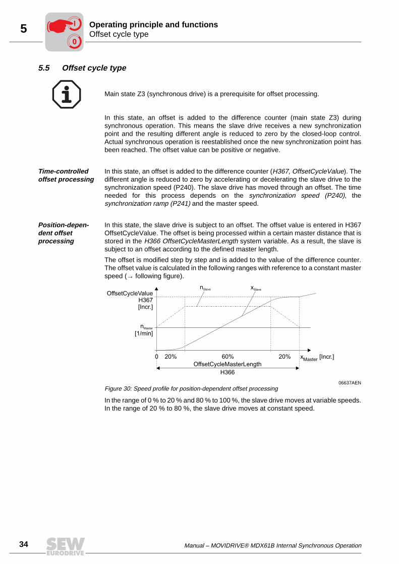
In this state, the slave drive is subject to an offset. The offset value is entered in H367OffsetCycleValue. The offset is being processed within a certain master distance that isstored in the H366 OffsetCycleMasterLength system variable. As a result, the slave issubject to an offset according to the defined master length.
The offset is modified step by step and is added to the value of the difference counter.The offset value is calculated in the following ranges with reference to a constant masterspeed (→ following figure).
In the range of 0 % to 20 % and 80 % to 100 %, the slave drive moves at variable speeds.In the range of 20 % to 80 %, the slave drive moves at constant speed.
Main state Z3 (synchronous drive) is a prerequisite for offset processing.
06637AENFigure 30: Speed profile for position-dependent offset processing
0
nMaster
[1/min]
xMaster
[Incr.]
nSlave
20% 60%
xSlave
OffsetCycleValueH367[Incr.]
20%
OffsetCycleMasterLength
H366
00
I

Manual – MOVIDRIVE® MDX61B Internal Synchronous Operation 35
5Offset cycle typeOperating principle and functions
Offset state machine
Offset control only reacts to required events in main state Z3 (synchronous drive). Thesetting is made using the H360 OffsetCycleMode system variable. Additional functionscan be programmed with the H361 OffsetCycleModeControl system variable.
H360 OffsetCycleMode system variable → Offset mode:
• OffsetCycleMode = 0
Manual offset processing using the IPOS application program by setting theH427SynchronousState system variable to the value 4.
• OffsetCycleMode = 1
Offset processing using binary inputs ("1" level) with H363 OffsetCycleInputMaskwith a resolution of 1 ms.
• OffsetCycleMode = 2 → reserved
• OffsetCycleMode = 3
Position control in conjunction with variables H364 OffsetCycleCounter and H365OffsetCycleCounterMaxValue), with remaining distance carryover.
06638AENFigure 31: Position-dependent offset cycle controlled by binary inputs
06639AENFigure 32: Position-controlled and position-dependent offset cycle
x [1/min]Slave
x [Incr.]Master
OffsetC
ycle
Va
lue
(H3
67
)
OffsetCycleMasterLength (H366)
"1"
"0"
DI..
x [1/min]Slave
x [Incr.]Master
OffsetC
ycle
Valu
e(H
367)
OffsetCycleMasterLength (H366)
OffsetCycleCounterMaxValue (H365)
00
I
36 Manual – MOVIDRIVE® MDX61B Internal Synchronous Operation
5 Offset cycle typeOperating principle and functions
H360 OffsetCycleModeControl system variable:
Offset state machine in H362 OffsetCycleState:
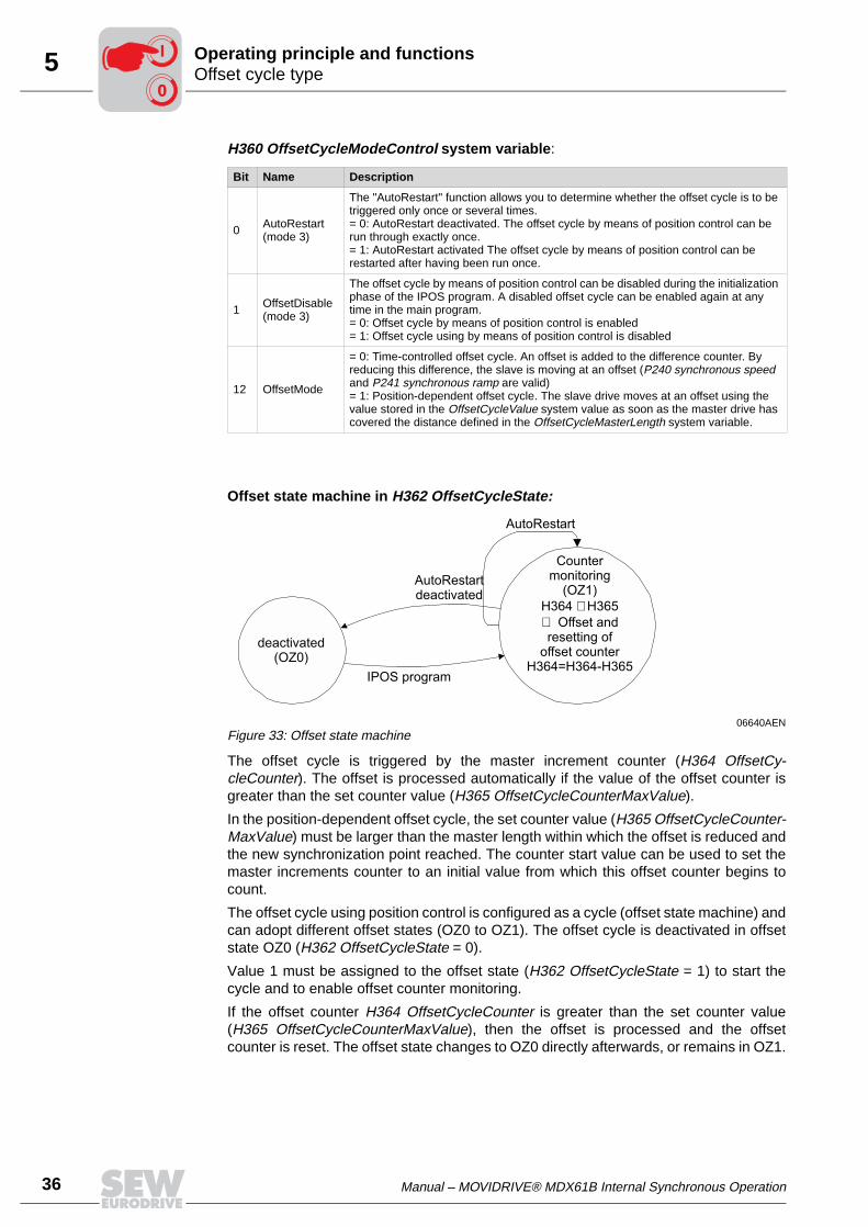
The offset cycle is triggered by the master increment counter (H364 OffsetCy-cleCounter). The offset is processed automatically if the value of the offset counter isgreater than the set counter value (H365 OffsetCycleCounterMaxValue).
In the position-dependent offset cycle, the set counter value (H365 OffsetCycleCounter-MaxValue) must be larger than the master length within which the offset is reduced andthe new synchronization point reached. The counter start value can be used to set themaster increments counter to an initial value from which this offset counter begins tocount.
The offset cycle using position control is configured as a cycle (offset state machine) andcan adopt different offset states (OZ0 to OZ1). The offset cycle is deactivated in offsetstate OZ0 (H362 OffsetCycleState = 0).
Value 1 must be assigned to the offset state (H362 OffsetCycleState = 1) to start thecycle and to enable offset counter monitoring.
If the offset counter H364 OffsetCycleCounter is greater than the set counter value(H365 OffsetCycleCounterMaxValue), then the offset is processed and the offsetcounter is reset. The offset state changes to OZ0 directly afterwards, or remains in OZ1.
Bit Name Description
0 AutoRestart(mode 3)
The "AutoRestart" function allows you to determine whether the offset cycle is to be triggered only once or several times.= 0: AutoRestart deactivated. The offset cycle by means of position control can be run through exactly once.= 1: AutoRestart activated The offset cycle by means of position control can be restarted after having been run once.
1 OffsetDisable(mode 3)
The offset cycle by means of position control can be disabled during the initialization phase of the IPOS program. A disabled offset cycle can be enabled again at any time in the main program.= 0: Offset cycle by means of position control is enabled= 1: Offset cycle using by means of position control is disabled
12 OffsetMode
= 0: Time-controlled offset cycle. An offset is added to the difference counter. By reducing this difference, the slave is moving at an offset (P240 synchronous speed and P241 synchronous ramp are valid)= 1: Position-dependent offset cycle. The slave drive moves at an offset using the value stored in the OffsetCycleValue system value as soon as the master drive has covered the distance defined in the OffsetCycleMasterLength system variable.
06640AENFigure 33: Offset state machine
deactivated(OZ0)
Countermonitoring
(OZ1)
H364 H365
Offset andresetting of
offset counterH364=H364-H365
IPOS program
AutoRestartdeactivated
AutoRestart
00
I
Manual – MOVIDRIVE® MDX61B Internal Synchronous Operation 37
5Stop cycle state machineOperating principle and functions
5.6 Stop cycle state machine
"Decoupling" (stop cycle) means that angular synchronous operation between the slaveand master drives is stopped and the slave drive enters the free running state. Thismeans the slave drive can be moved with speed control or held in its current positionwith position control.
Stop cycle mode control
Stop cycle mode control reacts in the main states Z3 (synchronous drive) and Z4(offset). The stop cycle process of the slave can either be performed manually orautomatically. The stop cycle mode is defined in the H400 StopCycleMode systemvariable. Additional functions can be programmed with the H401 StopCycleModeControlsystem variable.
During the stop cycle, the drive changes to speed 0 using ramp t11 (P130) with positioncontrol; or with speed control, the drive changes to the speed defined in the H439SpeedFreeMode system variable.
H400 StopCycleMode system variable → decoupling mode:
• StopCycleMode = 0
Manual decoupling. The slave exits synchronous operation with the master when theapplication assigns the value 5 to the H427 SynchronousState system variable.
• StopCycleMode = 1
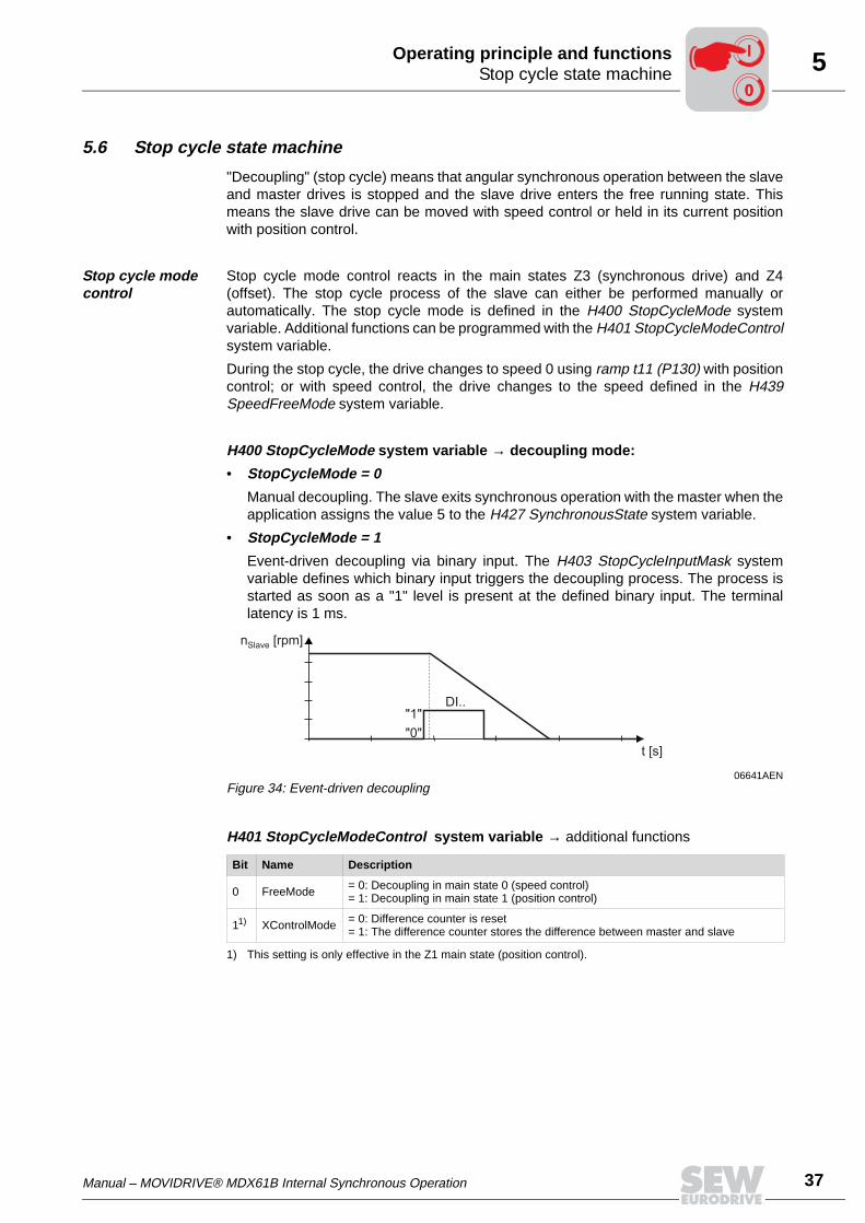
Event-driven decoupling via binary input. The H403 StopCycleInputMask systemvariable defines which binary input triggers the decoupling process. The process isstarted as soon as a "1" level is present at the defined binary input. The terminallatency is 1 ms.
H401 StopCycleModeControl system variable → additional functions
06641AENFigure 34: Event-driven decoupling
Bit Name Description
0 FreeMode = 0: Decoupling in main state 0 (speed control)= 1: Decoupling in main state 1 (position control)
11)
1) This setting is only effective in the Z1 main state (position control).
XControlMode = 0: Difference counter is reset= 1: The difference counter stores the difference between master and slave
n [rpm]Slave
t [s]
"1"
"0"
DI..
00
I
38 Manual – MOVIDRIVE® MDX61B Internal Synchronous Operation
5 Virtual encoderOperating principle and functions
5.7 Virtual encoder
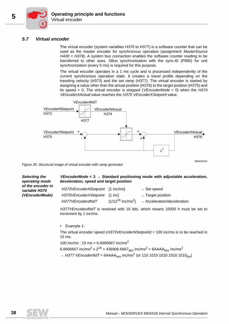
The virtual encoder (system variables H370 to H377) is a software counter that can beused as the master encoder for synchronous operation (assignment MasterSourceH430 = H376). A system bus connection enables the software counter reading to betransferred to other axes. SBus synchronization with the sync-ID (P885) for unitsynchronization (every 5 ms) is required for this purpose.
The virtual encoder operates in a 1 ms cycle and is processed independently of thecurrent synchronous operation state. It creates a travel profile depending on thetraveling velocity (H373) and the set ramp (H377). The virtual encoder is started byassigning a value other than the actual position (H376) to the target position (H375) andits speed > 0. The virtual encoder is stopped (VEncoderMode = 0) when the H374VEncoderXActual value reaches the H375 VEncoderXSetpoint value.
Selecting the operating mode of the encoder in variable H370 (VEncoderMode)
VEncoderMode = 3 → Standard positioning mode with adjustable acceleration,deceleration, speed and target position
H377VEncoderdNdT is resolved with 16 bits, which means 10000 h must be set toincrement by 1 inc/ms.
• Example 1:
The virtual encoder speed (H373VEncoderNSetpoint) = 100 inc/ms is to be reached in15 ms.
100 inc/ms : 15 ms = 6.6666667 inc/ms2
6.6666667 inc/ms2 x 216 = 436906.6667dec inc/ms2 = 6AAAAhex inc/ms2
→ H377 VEncoderNdT = 6AAAAhex inc/ms2 (or 110 1010 1010 1010 1010bin)
06642AXXFigure 35: Structural image of virtual encoder with ramp generator
+
VEncoderNSetpoint
H373
VEncoderdNdT
H377
VEncoderXSetpoint
H375
+
-+
VEncoderNActual
H374
VEncoderXActual
H376
z-1
H373VEncoderNSetpoint [1 inc/ms] → Set speed
H375VEncoderXSetpoint [1 inc] → Target position
H377VEncoderdNdT [1/1216 inc/ms2] → Acceleration/deceleration
00
I
Manual – MOVIDRIVE® MDX61B Internal Synchronous Operation 39
5Virtual encoderOperating principle and functions
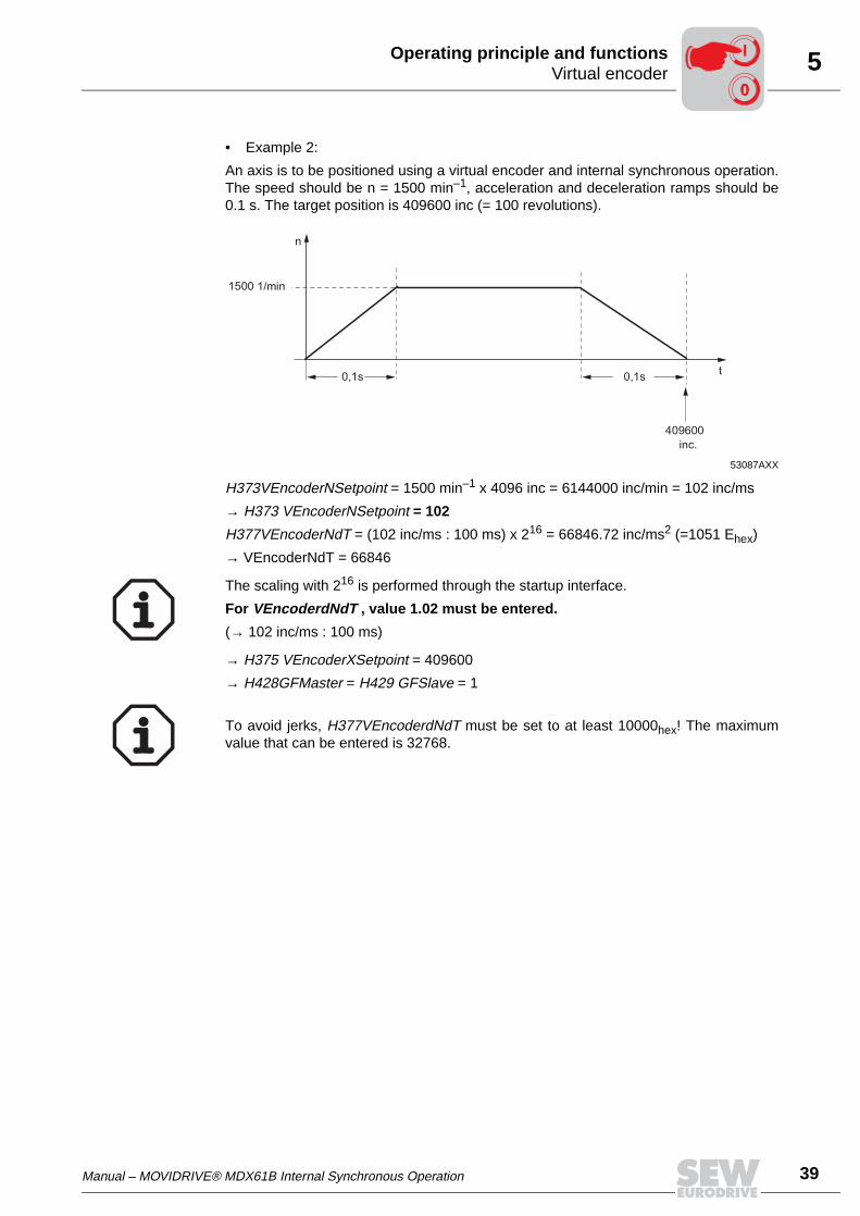
• Example 2:
An axis is to be positioned using a virtual encoder and internal synchronous operation.The speed should be n = 1500 min–1, acceleration and deceleration ramps should be0.1 s. The target position is 409600 inc (= 100 revolutions).
H373VEncoderNSetpoint = 1500 min–1 x 4096 inc = 6144000 inc/min = 102 inc/ms
→ H373 VEncoderNSetpoint = 102
H377VEncoderNdT = (102 inc/ms : 100 ms) x 216 = 66846.72 inc/ms2 (=1051 Ehex)
→ VEncoderNdT = 66846
→ H375 VEncoderXSetpoint = 409600
→ H428GFMaster = H429 GFSlave = 1
53087AXX
0,1s 0,1s
n
t
1500 1/min
409600
inc.
The scaling with 216 is performed through the startup interface.
For VEncoderdNdT , value 1.02 must be entered.
(→ 102 inc/ms : 100 ms)
To avoid jerks, H377VEncoderdNdT must be set to at least 10000hex! The maximumvalue that can be entered is 32768.
00
I
40 Manual – MOVIDRIVE® MDX61B Internal Synchronous Operation
5 Virtual encoderOperating principle and functions
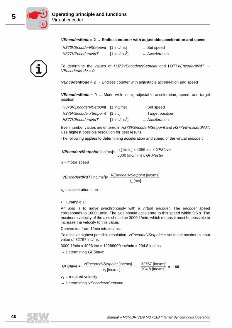
VEncoderMode = 2 → Endless counter with adjustable acceleration and speed
VEncoderMode = 2 → Endless counter with adjustable acceleration and speed
VEncoderMode = 0 → Mode with linear, adjustable acceleration, speed, and targetposition
Even number values are entered in H373VEncoderNSetpoint and H377VEncoderdNdT.Use highest possible resolution for best results.
The following applies to determining acceleration and speed of the virtual encoder:
n = motor speed
tA = acceleration time
• Example 1:
An axis is to move synchronously with a virtual encoder. The encoder speedcorresponds to 1000 1/min. The axis should accelerate to this speed within 0.5 s. Themaximum velocity of the axis should be 3000 1/min, which means it must be possible toincrease the velocity to this value.
Conversion from 1/min into inc/ms:
To achieve highest possible resolution, VEncoderNSetpoint is set to the maximum inputvalue of 32767 inc/ms.
3000 1/min x 4096 inc = 12288000 inc/min = 204.8 inc/ms
→ Determining GFSlave:
v1 = required velocity
→ Determining VEncoderNSetpoint:
H373VEncoderNSetpoint [1 inc/ms] → Set speed
H377VEncoderdNdT [1 inc/ms2] → Acceleration
To determine the values of H373VEncoderNSetpoint and H377VEncoderdNdT →VEncoderMode = 0.
H373VEncoderNSetpoint [1 inc/ms] → Set speed
H375VEncoderXSetpoint [1 inc] → Target position
H377VEncoderdNdT [1 inc/ms2] → Acceleration
VEncoderNSetpoint [inc/ms]=n [1/min] x 4096 inc x GFSlave
6000 [inc/min] x GFMaster
VEncoderdNdT [inc/ms ]=2 VEncoderNSetpoint [inc/ms]
t [ms]A
GFSlave =VEncoderNSetpoint [inc/ms]
v [inc/ms]1
=32767 [inc/ms]
204,8 [inc/ms]= 160
00
I
Manual – MOVIDRIVE® MDX61B Internal Synchronous Operation 41
5Virtual encoderOperating principle and functions
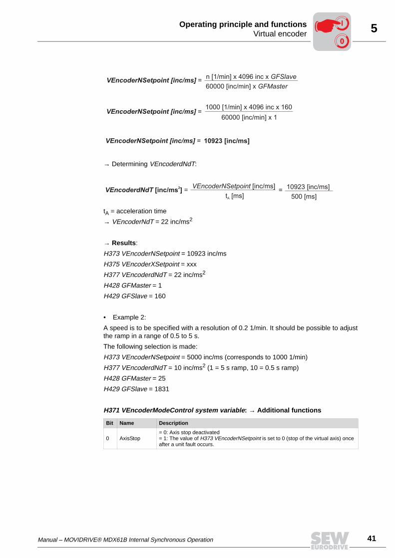
→ Determining VEncoderdNdT:
tA = acceleration time
→ VEncoderNdT = 22 inc/ms2
→ Results:
H373 VEncoderNSetpoint = 10923 inc/ms
H375 VEncoderXSetpoint = xxx
H377 VEncoderdNdT = 22 inc/ms2
H428 GFMaster = 1
H429 GFSlave = 160
• Example 2:
A speed is to be specified with a resolution of 0.2 1/min. It should be possible to adjustthe ramp in a range of 0.5 to 5 s.
The following selection is made:
H373 VEncoderNSetpoint = 5000 inc/ms (corresponds to 1000 1/min)
H377 VEncoderdNdT = 10 inc/ms2 (1 = 5 s ramp, 10 = 0.5 s ramp)
H428 GFMaster = 25
H429 GFSlave = 1831
H371 VEncoderModeControl system variable: → Additional functions
Bit Name Description
0 AxisStop= 0: Axis stop deactivated= 1: The value of H373 VEncoderNSetpoint is set to 0 (stop of the virtual axis) once after a unit fault occurs.
VEncoderNSetpoint [inc/ms] =
VEncoderNSetpoint [inc/ms] =
n [1/min] x 4096 inc x GFSlave
60000 [inc/min] x GFMaster
1000 [1/min] x 4096 inc x 160
60000 [inc/min] x 1
VEncoderNSetpoint [inc/ms] = 10923 [inc/ms]
VEncoderdNdT =[inc/ms ]2 VEncoderNSetpoint [inc/ms]
t [ms]A
10923 [inc/ms]
500 [ms]=
00
I
42 Manual – MOVIDRIVE® MDX61B Internal Synchronous Operation
5 Important notesOperating principle and functions
5.8 Important notes
• The possibility of specifying a signed distance in variable H417 StartupCycleMaster-Length and H366 OffsetCycleMasterLength for the master drive means it is importantto check the direction of rotation of the master drive. It is also important to note thatthe scaling factor can also be entered as signed value in H428 GFMaster.
• A lag error is only triggered (P923 Lag error window) in main state Z3 (synchronousdrive).
• Set zero point: The 64-bit counter can be cleared by programming an input terminalwith "Set DRS zero point."
• A value other than zero should be entered in the H390 RegisterLoopDXDTOutsystem variable to achieve exact results in position-dependent synchronization andto allow that the remaining distance can be reduced. In addition, the functionRegisterScale must be activated so the correction value is multiplied by the scalingfactor of the slave.
→ Example:
H390 RegisterLoopDXDTOut = 2
H426 SynchronousModeControl.2 (RegisterScale – H426) = 1
Master/slave scaling factors
The objective of phase-synchronous operation is to move the outputs of two or moredrives and thus the line synchronously in relation to one another. The synchronous op-eration controller required for this purpose only processes information on increments ofa master encoder and a slave encoder. This means the actual gear units and additionalgear ratios of the application have to be represented by factors. This way,synchronization can be achieved within a certain proportionality ratio.
If two identical drives are used, which means same gear unit reduction ratios, sameadditional gears, etc., then the proportionality ratio is one-to-one.
If unequal gear unit reduction ratios occur, they are taken into account with the masterdrive by the scaling factor H428 GFMaster and with the slave drive by the scaling factorH429 GFSlave.
The H428 GFMaster scaling factor evaluates the master increments, which thesynchronous operation controller obtains as setpoints. The GFMaster scaling factor alsoincludes the slave gear unit reduction ratio, the slave encoder resolution, additionalslave gear if present, and the master length.
→ Calculating H428 GFMaster:
GFMaster = slave gear unit reduction ratio x additional slave gear x master length
The master length relates to the length of travel performed by the master per revolutionof the output.
→ Calculating H429 GFSlave:
GFSlave = master gear unit reduction ratio x master additional gear x slave length
The slave length relates to the length of travel performed by the slave per revolution ofthe output.
00
I
Manual – MOVIDRIVE® MDX61B Internal Synchronous Operation 43
5Important notesOperating principle and functions
• Master / slave gear unit reduction ratio
As a rule, the master or slave gear unit reduction ratio is indicated on the nameplateof the drive. You can either directly read the value or calculate it from the quotient ofthe rated speed / output speed.
For forwards and backwards movements in a restricted travel range, it is generallysufficient to scale up the gear unit reduction ratio from the nameplate or obtained bycalculation to between two and four decimal places (depending on the maximumpossible resolution of the scaling factor).
• Master / slave additional gear ratio
If there is an additional gear for a further ratio reduction, this additional gear reductionratio must be treated like an additional gear unit reduction ratio and is also includedin the calculation.
• Master / inverter length
The master length relates to the length of travel performed by the master / slave perrevolution of the output.
In many applications, the length of travel is described to a sufficient degree ofaccuracy by the calculated circumference of the drive wheel. The number can be anirrational number. In the case of endless applications, it is therefore recommendedthat you calculate the length of travel according to the mechanical system used.
– Applications with a chain sprocket as transmission element:Travel length = Number of teeth of the chain sprocket x chain link length
– Applications with a gear rack as transmission element:Travel length = Number of teeth of the gear wheel x tooth clearance (tip-to-tip) ofthe gear rack
– Applications with a toothed belt as transmission element:Travel length = Number of teeth of the gear wheel x tooth clearance (center-to-center) of the toothed belt
– Applications with a spindle as transmission element:Travel length = Spindle pitch
For synchronous operation is recommended that you include the individualnumbers of teeth of the gear pairs in the scaling factor calculation. In other words,include the individual gear unit reduction stages in the calculation separately.Your SEW-EURODRIVE contact can tell you the numbers of teeth in the gear pairs.
00
I
44 Manual – MOVIDRIVE® MDX61B Internal Synchronous Operation
5 Important notesOperating principle and functions
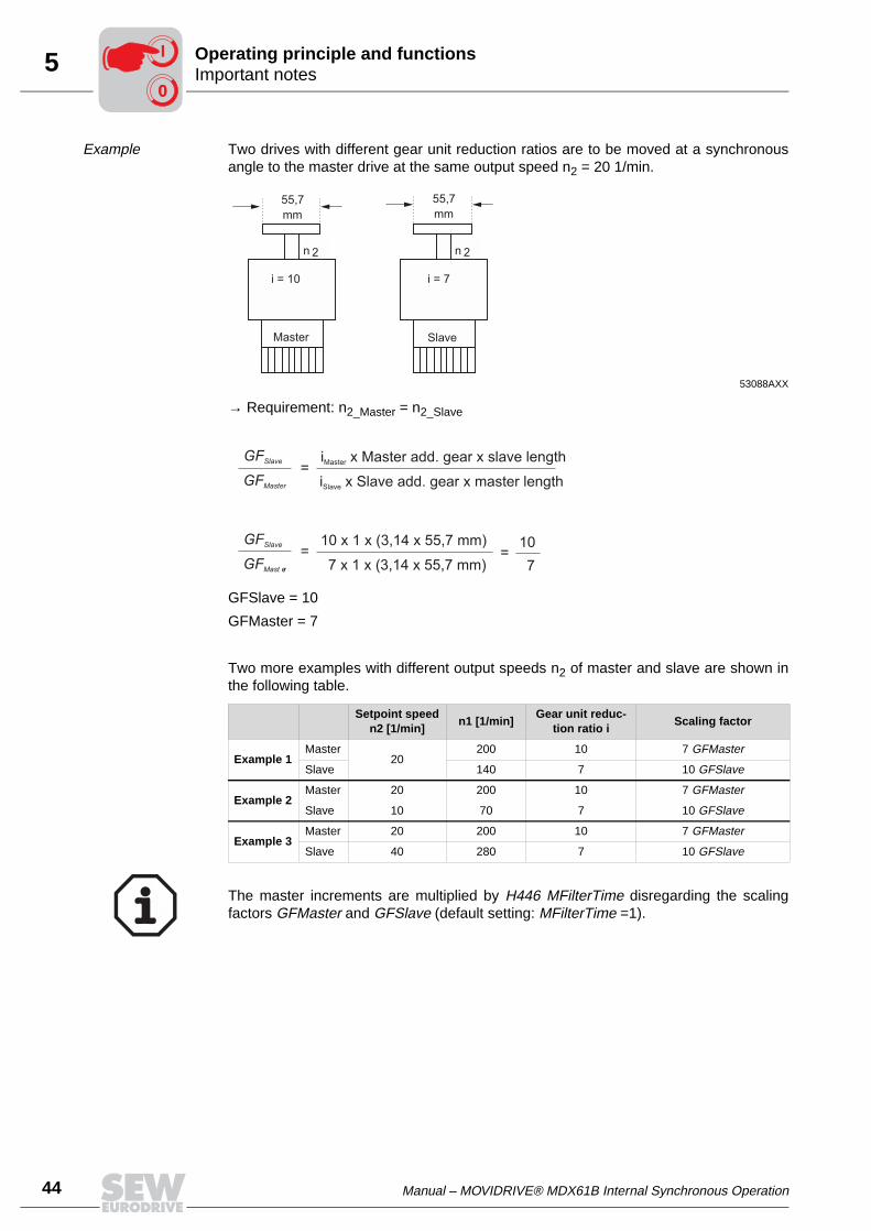
Example Two drives with different gear unit reduction ratios are to be moved at a synchronousangle to the master drive at the same output speed n2 = 20 1/min.
→ Requirement: n2_Master = n2_Slave
GFSlave = 10
GFMaster = 7
Two more examples with different output speeds n2 of master and slave are shown inthe following table.
53088AXX
Setpoint speedn2 [1/min]
n1 [1/min]Gear unit reduc-
tion ratio iScaling factor
Example 1Master
20200 10 7 GFMaster
Slave 140 7 10 GFSlave
Example 2Master 20 200 10 7 GFMaster
Slave 10 70 7 10 GFSlave
Example 3Master 20 200 10 7 GFMaster
Slave 40 280 7 10 GFSlave
n 2 n 2
Master
i = 10
Slave
i = 7
55,7 mm
55,7
mm
GFSlave
GFMast er
10 x 1 x (3,14 x 55,7 mm)
7 x 1 x (3,14 x 55,7 mm)= =
10
7
The master increments are multiplied by H446 MFilterTime disregarding the scalingfactors GFMaster and GFSlave (default setting: MFilterTime =1).
00
I
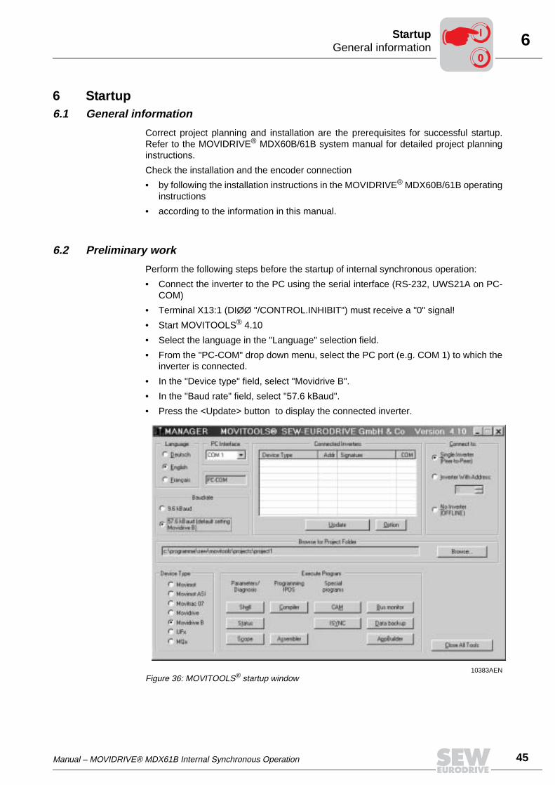
Manual – MOVIDRIVE® MDX61B Internal Synchronous Operation 45
6General informationStartup
6 Startup6.1 General information
Correct project planning and installation are the prerequisites for successful startup.Refer to the MOVIDRIVE® MDX60B/61B system manual for detailed project planninginstructions.
Check the installation and the encoder connection
• by following the installation instructions in the MOVIDRIVE® MDX60B/61B operatinginstructions
• according to the information in this manual.
6.2 Preliminary work
Perform the following steps before the startup of internal synchronous operation:
• Connect the inverter to the PC using the serial interface (RS-232, UWS21A on PC-COM)
• Terminal X13:1 (DIØØ "/CONTROL.INHIBIT") must receive a "0" signal!
• Start MOVITOOLS® 4.10
• Select the language in the "Language" selection field.
• From the "PC-COM" drop down menu, select the PC port (e.g. COM 1) to which theinverter is connected.
• In the "Device type" field, select "Movidrive B".
• In the "Baud rate" field, select "57.6 kBaud".
• Press the <Update> button to display the connected inverter.
10383AENFigure 36: MOVITOOLS® startup window
00
I
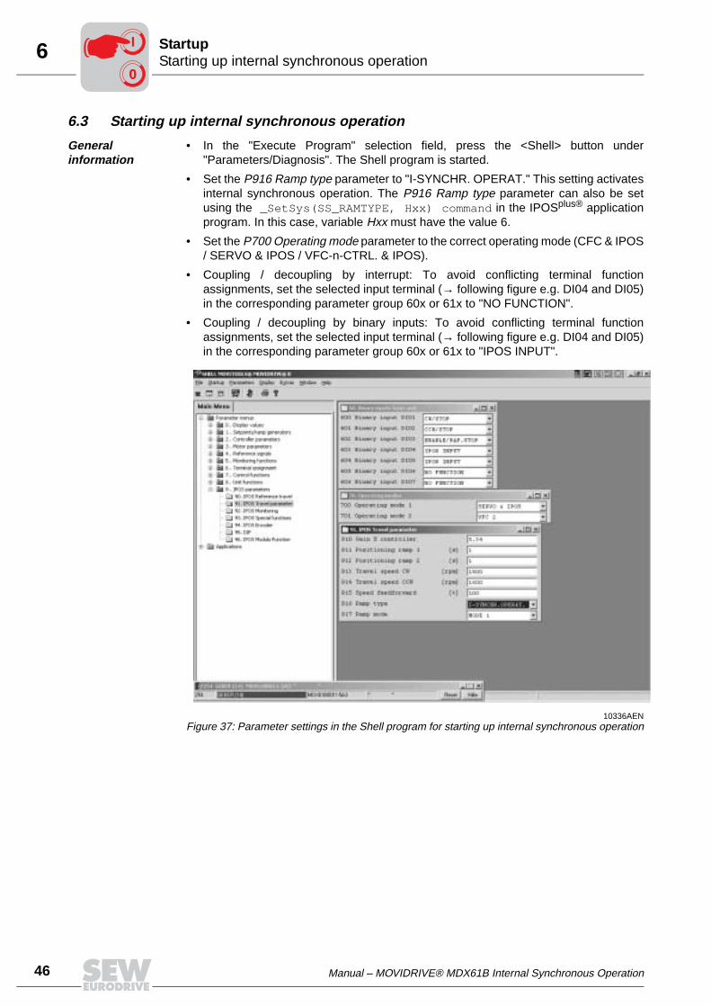
46 Manual – MOVIDRIVE® MDX61B Internal Synchronous Operation
6 Starting up internal synchronous operationStartup
6.3 Starting up internal synchronous operation
General information
• In the "Execute Program" selection field, press the <Shell> button under"Parameters/Diagnosis". The Shell program is started.
• Set the P916 Ramp type parameter to "I-SYNCHR. OPERAT." This setting activatesinternal synchronous operation. The P916 Ramp type parameter can also be setusing the _SetSys(SS_RAMTYPE, Hxx) command in the IPOSplus® applicationprogram. In this case, variable Hxx must have the value 6.
• Set the P700 Operating mode parameter to the correct operating mode (CFC & IPOS/ SERVO & IPOS / VFC-n-CTRL. & IPOS).
• Coupling / decoupling by interrupt: To avoid conflicting terminal functionassignments, set the selected input terminal (→ following figure e.g. DI04 and DI05)in the corresponding parameter group 60x or 61x to "NO FUNCTION".
• Coupling / decoupling by binary inputs: To avoid conflicting terminal functionassignments, set the selected input terminal (→ following figure e.g. DI04 and DI05)in the corresponding parameter group 60x or 61x to "IPOS INPUT".
10336AENFigure 37: Parameter settings in the Shell program for starting up internal synchronous operation
00
I
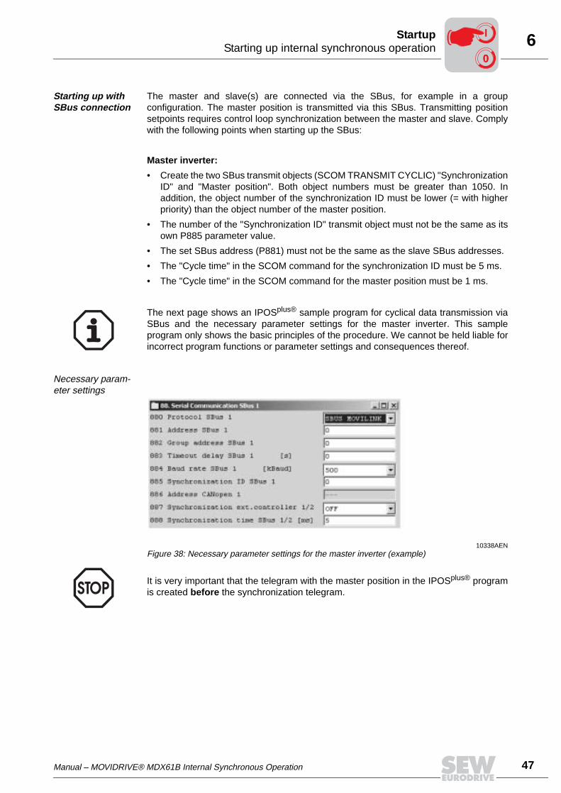
Manual – MOVIDRIVE® MDX61B Internal Synchronous Operation 47
6Starting up internal synchronous operationStartup
Starting up with SBus connection
The master and slave(s) are connected via the SBus, for example in a groupconfiguration. The master position is transmitted via this SBus. Transmitting positionsetpoints requires control loop synchronization between the master and slave. Complywith the following points when starting up the SBus:
Master inverter:
• Create the two SBus transmit objects (SCOM TRANSMIT CYCLIC) "SynchronizationID" and "Master position". Both object numbers must be greater than 1050. Inaddition, the object number of the synchronization ID must be lower (= with higherpriority) than the object number of the master position.
• The number of the "Synchronization ID" transmit object must not be the same as itsown P885 parameter value.
• The set SBus address (P881) must not be the same as the slave SBus addresses.
• The "Cycle time" in the SCOM command for the synchronization ID must be 5 ms.
• The "Cycle time" in the SCOM command for the master position must be 1 ms.
Necessary param-eter settings
The next page shows an IPOSplus® sample program for cyclical data transmission viaSBus and the necessary parameter settings for the master inverter. This sampleprogram only shows the basic principles of the procedure. We cannot be held liable forincorrect program functions or parameter settings and consequences thereof.
10338AENFigure 38: Necessary parameter settings for the master inverter (example)
It is very important that the telegram with the master position in the IPOSplus® programis created before the synchronization telegram.
00
I
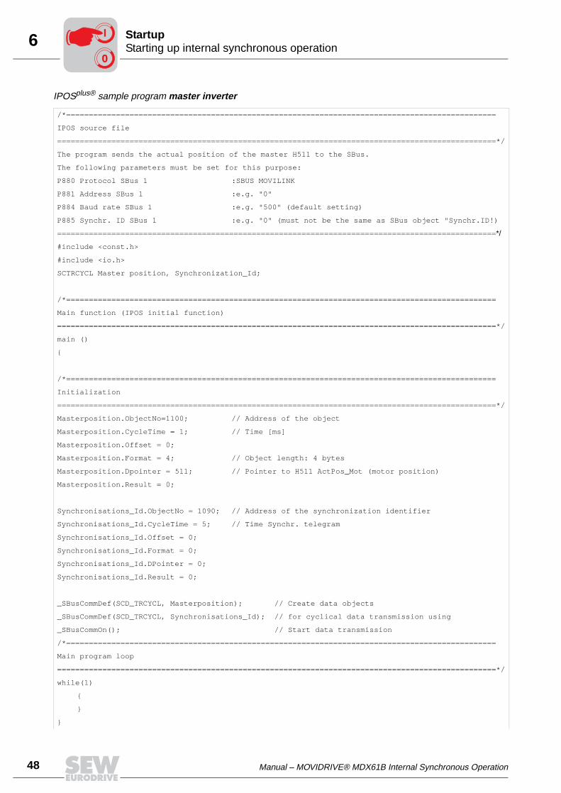
48 Manual – MOVIDRIVE® MDX61B Internal Synchronous Operation
6 Starting up internal synchronous operationStartup
IPOSplus® sample program master inverter
/*===============================================================================================
IPOS source file
=================================================================================================*/
The program sends the actual position of the master H511 to the SBus.
The following parameters must be set for this purpose:
P880 Protocol SBus 1 :SBUS MOVILINK
P881 Address SBus 1 :e.g. "0"
P884 Baud rate SBus 1 :e.g. "500" (default setting)
P885 Synchr. ID SBus 1 :e.g. "0" (must not be the same as SBus object "Synchr.ID!)
=================================================================================================*/
#include <const.h>
#include <io.h>
SCTRCYCL Master position, Synchronization_Id;
/*===============================================================================================
Main function (IPOS initial function)
=================================================================================================*/
main ()
/*===============================================================================================
Initialization
=================================================================================================*/
Masterposition.ObjectNo=1100; // Address of the object
Masterposition.CycleTime = 1; // Time [ms]
Masterposition.Offset = 0;
Masterposition.Format = 4; // Object length: 4 bytes
Masterposition.Dpointer = 511; // Pointer to H511 ActPos_Mot (motor position)
Masterposition.Result = 0;
Synchronisations_Id.ObjectNo = 1090; // Address of the synchronization identifier
Synchronisations_Id.CycleTime = 5; // Time Synchr. telegram
Synchronisations_Id.Offset = 0;
Synchronisations_Id.Format = 0;
Synchronisations_Id.DPointer = 0;
Synchronisations_Id.Result = 0;
_SBusCommDef(SCD_TRCYCL, Masterposition); // Create data objects
_SBusCommDef(SCD_TRCYCL, Synchronisations_Id); // for cyclical data transmission using
_SBusCommOn(); // Start data transmission
/*===============================================================================================
Main program loop
=================================================================================================*/
while(1)
00
I
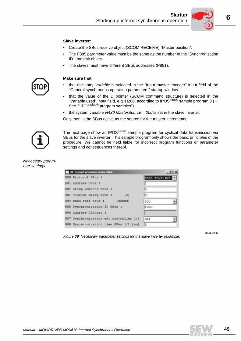
Manual – MOVIDRIVE® MDX61B Internal Synchronous Operation 49
6Starting up internal synchronous operationStartup
Slave inverter:
• Create the SBus receive object (SCOM RECEIVE) "Master position".
• The P885 parameter value must be the same as the number of the "SynchronizationID" transmit object.
• The slaves must have different SBus addresses (P881).
Necessary param-eter settings
Make sure that
• that the entry Variable is selected in the "Input master encoder" input field of the"General synchronous operation parameters" startup window
• that the value of the D pointer (SCOM command structure) is selected in the"Variable used" input field, e.g. H200, according to IPOSplus® sample program 3 (→Sec. " IPOSplus® program samples")
• the system variable H430 MasterSource = 200 is set in the slave inverter.
Only then is the SBus active as the source for the master increments.
The next page show an IPOSplus® sample program for cyclical data transmission viaSBus for the slave inverter. This sample program only shows the basic principles of theprocedure. We cannot be held liable for incorrect program functions or parametersettings and consequences thereof.
10339AENFigure 39: Necessary parameter settings for the slave inverter (example)
00
I
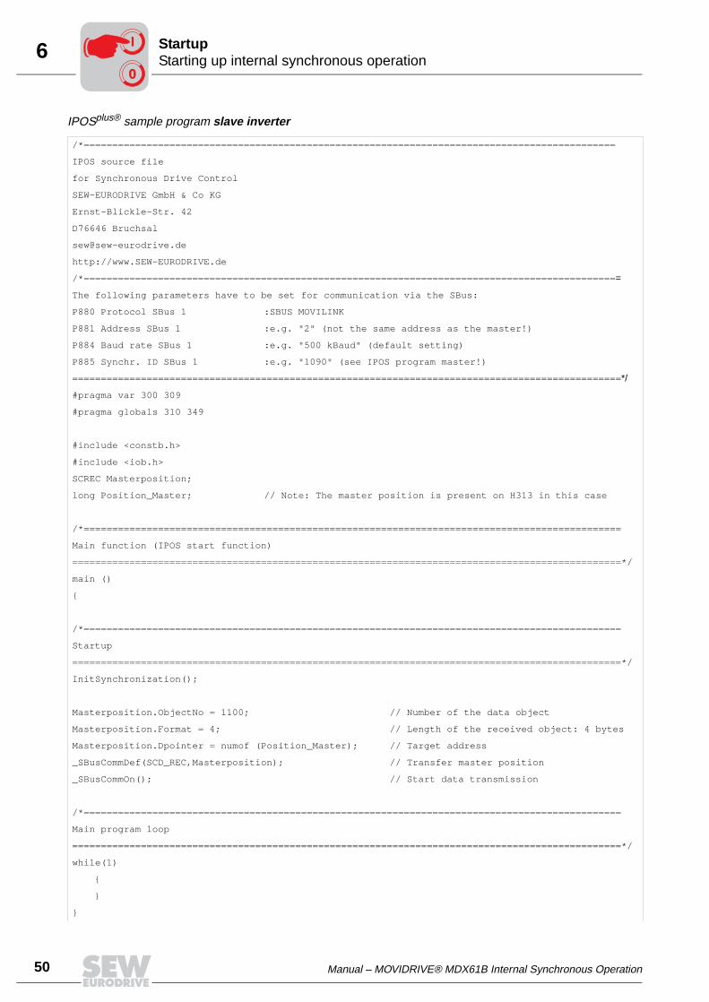
50 Manual – MOVIDRIVE® MDX61B Internal Synchronous Operation
6 Starting up internal synchronous operationStartup
IPOSplus® sample program slave inverter
/*=============================================================================================
IPOS source file
for Synchronous Drive Control
SEW-EURODRIVE GmbH & Co KG
Ernst-Blickle-Str. 42
D76646 Bruchsal
http://www.SEW-EURODRIVE.de
/*==============================================================================================
The following parameters have to be set for communication via the SBus:
P880 Protocol SBus 1 :SBUS MOVILINK
P881 Address SBus 1 :e.g. "2" (not the same address as the master!)
P884 Baud rate SBus 1 :e.g. "500 kBaud" (default setting)
P885 Synchr. ID SBus 1 :e.g. "1090" (see IPOS program master!)
================================================================================================*/
#pragma var 300 309
#pragma globals 310 349
#include <constb.h>
#include <iob.h>
SCREC Masterposition;
long Position_Master; // Note: The master position is present on H313 in this case
/*==============================================================================================
Main function (IPOS start function)
================================================================================================*/
main ()
/*==============================================================================================
Startup
================================================================================================*/
InitSynchronization();
Masterposition.ObjectNo = 1100; // Number of the data object
Masterposition.Format = 4; // Length of the received object: 4 bytes
Masterposition.Dpointer = numof (Position_Master); // Target address
_SBusCommDef(SCD_REC,Masterposition); // Transfer master position
_SBusCommOn(); // Start data transmission
/*==============================================================================================
Main program loop
================================================================================================*/
while(1)
00
I
Manual – MOVIDRIVE® MDX61B Internal Synchronous Operation 51
6Starting up internal synchronous operationStartup
Startup with slave prone to slip with absolute encoder on the travel path
The absolute position of a connected and evaluated absolute encoder is used as themaster for internal synchronous operation. The absolute encoder can be connected asfollows:
• to X62 of the DIP11B option (→ only for MOVIDRIVE® MDX61B sizes 1 to 6)
• to X14 of the DEH11B (Hiperface®) or DER11B (resolver) option
Make sure that
• the entry SSI encoder is selected in the "Input master encoder" input field of the"General synchronous operation parameters" startup window
• the slave source is set correctly in the H431 SlaveSource system variable:
– H431 = 0 Source of actual position is X15– H431 > 0 Pointer to variable, e.g. H431 = 510 // Source actual position X14 (H510
ActPos_Ext)
00
I
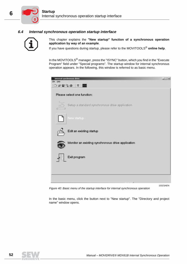
52 Manual – MOVIDRIVE® MDX61B Internal Synchronous Operation
6 Internal synchronous operation startup interfaceStartup
6.4 Internal synchronous operation startup interface
In the MOVITOOLS® manager, press the "ISYNC" button, which you find in the "ExecuteProgram" field under "Special programs". The startup window for internal synchronousoperation appears. In the following, this window is referred to as basic menu.
In the basic menu, click the button next to "New startup". The "Directory and projectname" window opens.
This chapter explains the "New startup" function of a synchronous operationapplication by way of an example.
If you have questions during startup, please refer to the MOVITOOLS® online help.
10323AENFigure 40: Basic menu of the startup interface for internal synchronous operation
00
I
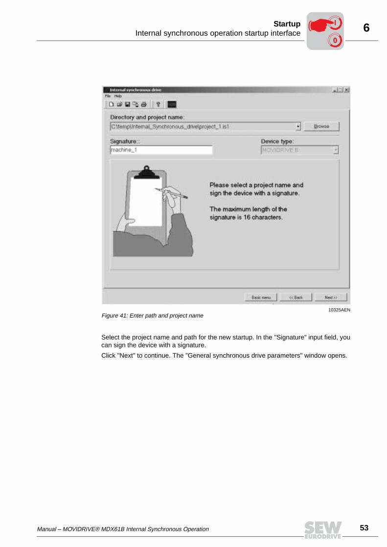
Manual – MOVIDRIVE® MDX61B Internal Synchronous Operation 53
6Internal synchronous operation startup interfaceStartup
Select the project name and path for the new startup. In the "Signature" input field, youcan sign the device with a signature.
Click "Next" to continue. The "General synchronous drive parameters" window opens.
10325AENFigure 41: Enter path and project name
00
I
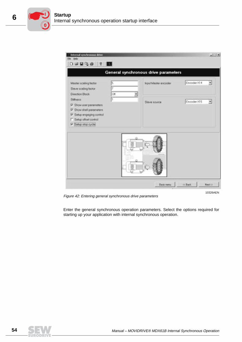
54 Manual – MOVIDRIVE® MDX61B Internal Synchronous Operation
6 Internal synchronous operation startup interfaceStartup
Enter the general synchronous operation parameters. Select the options required forstarting up your application with internal synchronous operation.
10326AENFigure 42: Entering general synchronous drive parameters
00
I
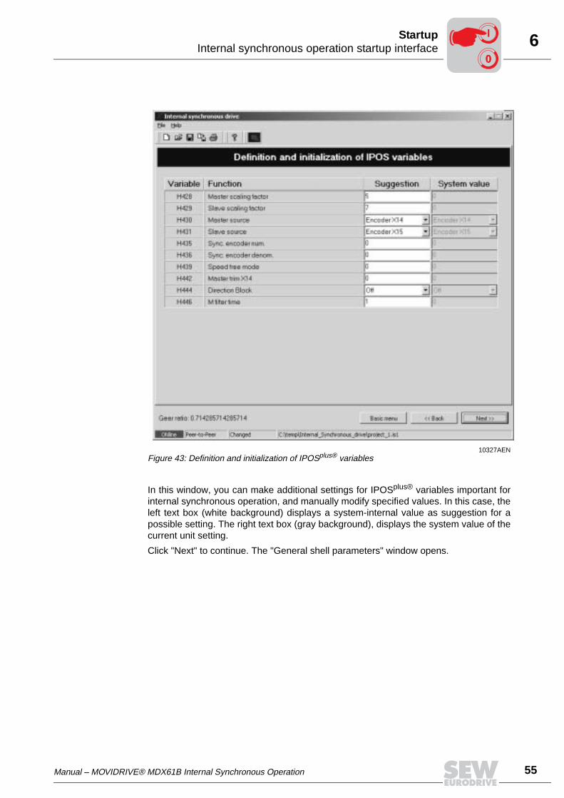
Manual – MOVIDRIVE® MDX61B Internal Synchronous Operation 55
6Internal synchronous operation startup interfaceStartup
In this window, you can make additional settings for IPOSplus® variables important forinternal synchronous operation, and manually modify specified values. In this case, theleft text box (white background) displays a system-internal value as suggestion for apossible setting. The right text box (gray background), displays the system value of thecurrent unit setting.
Click "Next" to continue. The "General shell parameters" window opens.
10327AENFigure 43: Definition and initialization of IPOSplus® variables
00
I
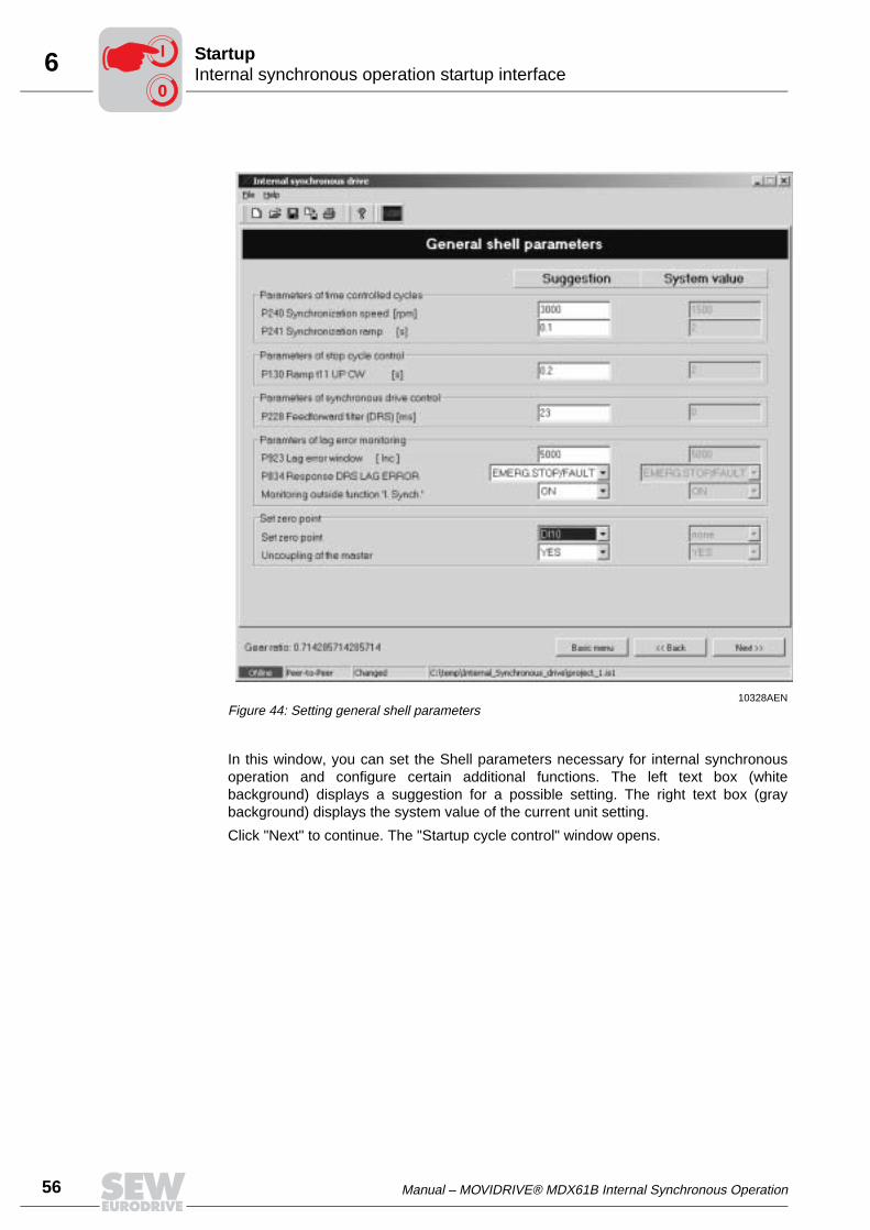
56 Manual – MOVIDRIVE® MDX61B Internal Synchronous Operation
6 Internal synchronous operation startup interfaceStartup
In this window, you can set the Shell parameters necessary for internal synchronousoperation and configure certain additional functions. The left text box (whitebackground) displays a suggestion for a possible setting. The right text box (graybackground) displays the system value of the current unit setting.
Click "Next" to continue. The "Startup cycle control" window opens.
10328AENFigure 44: Setting general shell parameters
00
I
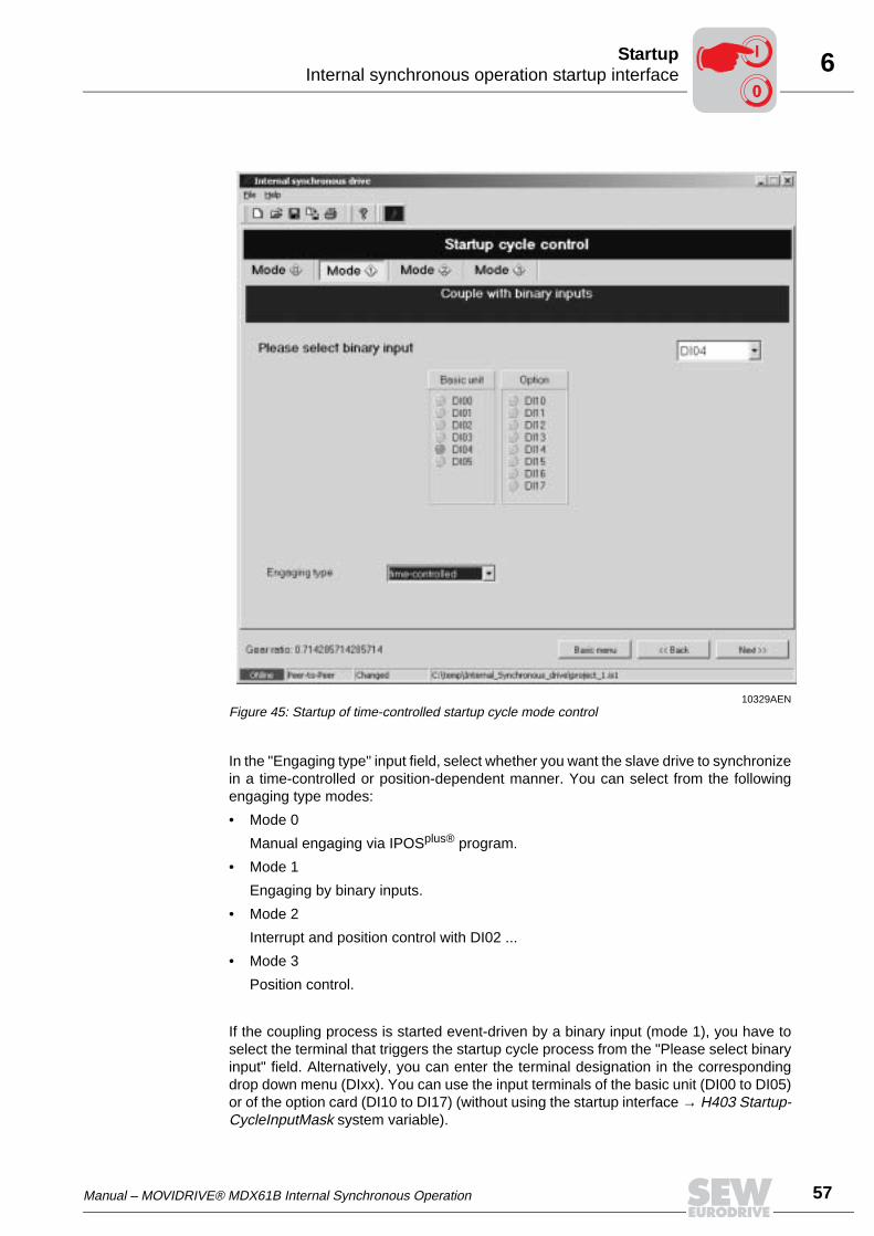
Manual – MOVIDRIVE® MDX61B Internal Synchronous Operation 57
6Internal synchronous operation startup interfaceStartup
In the "Engaging type" input field, select whether you want the slave drive to synchronizein a time-controlled or position-dependent manner. You can select from the followingengaging type modes:
• Mode 0
Manual engaging via IPOSplus® program.
• Mode 1
Engaging by binary inputs.
• Mode 2
Interrupt and position control with DI02 ...
• Mode 3
Position control.
If the coupling process is started event-driven by a binary input (mode 1), you have toselect the terminal that triggers the startup cycle process from the "Please select binaryinput" field. Alternatively, you can enter the terminal designation in the correspondingdrop down menu (DIxx). You can use the input terminals of the basic unit (DI00 to DI05)or of the option card (DI10 to DI17) (without using the startup interface → H403 Startup-CycleInputMask system variable).
10329AENFigure 45: Startup of time-controlled startup cycle mode control
00
I
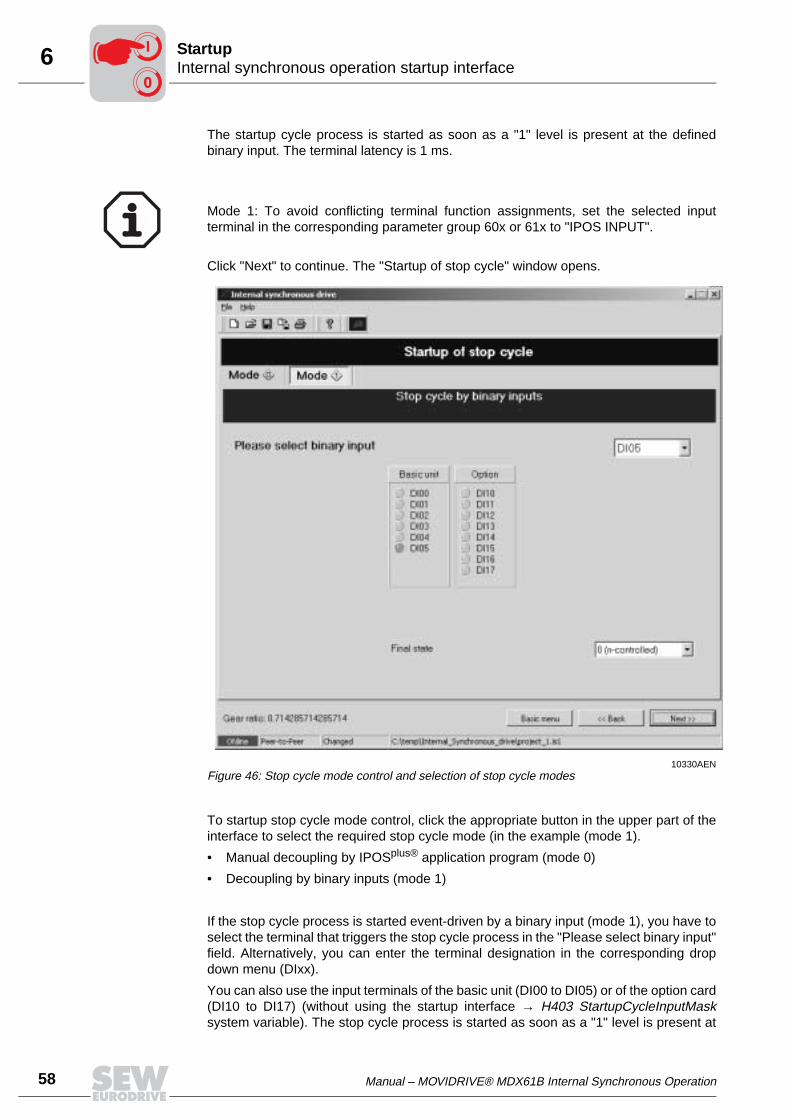
58 Manual – MOVIDRIVE® MDX61B Internal Synchronous Operation
6 Internal synchronous operation startup interfaceStartup
The startup cycle process is started as soon as a "1" level is present at the definedbinary input. The terminal latency is 1 ms.
Click "Next" to continue. The "Startup of stop cycle" window opens.
To startup stop cycle mode control, click the appropriate button in the upper part of theinterface to select the required stop cycle mode (in the example (mode 1).
• Manual decoupling by IPOSplus® application program (mode 0)
• Decoupling by binary inputs (mode 1)
If the stop cycle process is started event-driven by a binary input (mode 1), you have toselect the terminal that triggers the stop cycle process in the "Please select binary input"field. Alternatively, you can enter the terminal designation in the corresponding dropdown menu (DIxx).
You can also use the input terminals of the basic unit (DI00 to DI05) or of the option card(DI10 to DI17) (without using the startup interface → H403 StartupCycleInputMasksystem variable). The stop cycle process is started as soon as a "1" level is present at
Mode 1: To avoid conflicting terminal function assignments, set the selected inputterminal in the corresponding parameter group 60x or 61x to "IPOS INPUT".
10330AENFigure 46: Stop cycle mode control and selection of stop cycle modes
00
I
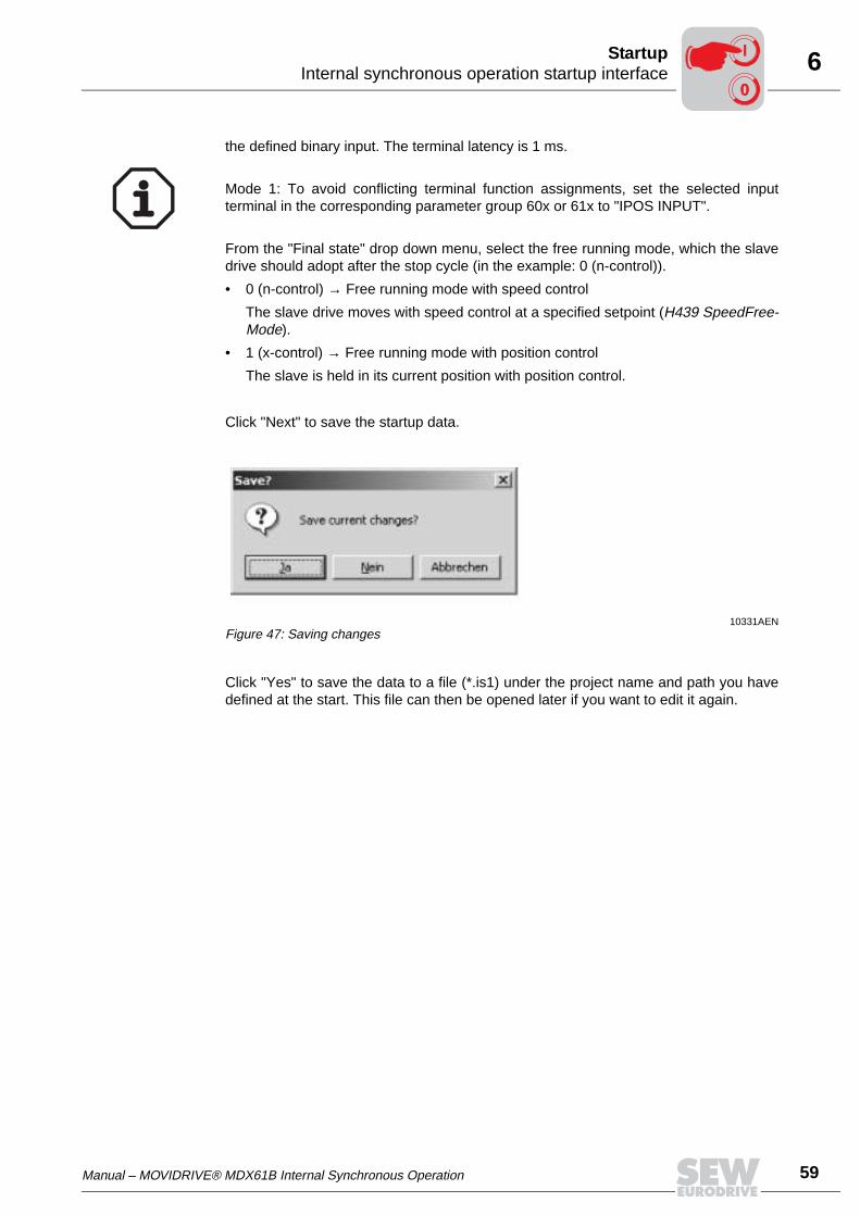
Manual – MOVIDRIVE® MDX61B Internal Synchronous Operation 59
6Internal synchronous operation startup interfaceStartup
the defined binary input. The terminal latency is 1 ms.
From the "Final state" drop down menu, select the free running mode, which the slavedrive should adopt after the stop cycle (in the example: 0 (n-control)).
• 0 (n-control) → Free running mode with speed control
The slave drive moves with speed control at a specified setpoint (H439 SpeedFree-Mode).
• 1 (x-control) → Free running mode with position control
The slave is held in its current position with position control.
Click "Next" to save the startup data.
Click "Yes" to save the data to a file (*.is1) under the project name and path you havedefined at the start. This file can then be opened later if you want to edit it again.
Mode 1: To avoid conflicting terminal function assignments, set the selected inputterminal in the corresponding parameter group 60x or 61x to "IPOS INPUT".
10331AENFigure 47: Saving changes
00
I
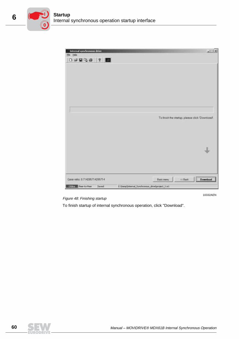
60 Manual – MOVIDRIVE® MDX61B Internal Synchronous Operation
6 Internal synchronous operation startup interfaceStartup
To finish startup of internal synchronous operation, click "Download".
10332AENFigure 48: Finishing startup
00
I
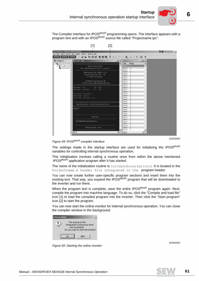
Manual – MOVIDRIVE® MDX61B Internal Synchronous Operation 61
6Internal synchronous operation startup interfaceStartup
The Compiler interface for IPOSplus® programming opens. The interface appears with aprogram text and with an IPOSplus® source file called "Projectname.ipc".
The settings made in the startup interface are used for initializing the IPOSplus®
variables for controlling internal synchronous operation.
This initialization involves calling a routine once from within the above mentionedIPOSplus® application program after it has started.
The name of the initialization routine is InitSynchronization() It is located in theProjectname.h header file integrated in the program header.
You can now create further user-specific program sections and insert them into theexisting text. That way, you expand the IPOSplus® program that will be downloaded tothe inverter and run there.
When the program text is complete, save the entire IPOSplus® program again. Next,compile the program into machine language. To do so, click the "Compile and load file"icon [1] to load the compiled program into the inverter. Then click the "Start program"icon [2] to start the program.
You can now start the online monitor for internal synchronous operation. You can closethe compiler window in the background.
10333AENFigure 49: IPOSplus® compiler interface
10334AENFigure 50: Starting the online monitor
00
I

62 Manual – MOVIDRIVE® MDX61B Internal Synchronous Operation
6 Internal synchronous operation startup interfaceStartup
The online monitor serves to view the current main state of the ongoing synchronousoperation application or to check the lag distance.
To exit the program, click "Next". The basic menu opens. In the basic menu, click "Exitprogram".
10335AENFigure 51: Display of the current main state
00
I
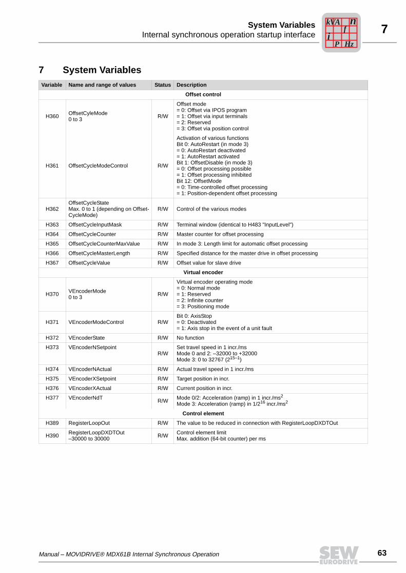
Manual – MOVIDRIVE® MDX61B Internal Synchronous Operation 63
7Internal synchronous operation startup interfaceSystem Variables
7 System VariablesVariable Name and range of values Status Description
Offset control
H360 OffsetCyleMode0 to 3 R/W
Offset mode= 0: Offset via IPOS program= 1: Offset via input terminals= 2: Reserved= 3: Offset via position control
H361 OffsetCycleModeControl R/W
Activation of various functionsBit 0: AutoRestart (in mode 3)= 0: AutoRestart deactivated= 1: AutoRestart activatedBit 1: OffsetDisable (in mode 3)= 0: Offset processing possible= 1: Offset processing inhibitedBit 12: OffsetMode= 0: Time-controlled offset processing= 1: Position-dependent offset processing
H362OffsetCycleStateMax. 0 to 1 (depending on Offset-CycleMode)
R/W Control of the various modes
H363 OffsetCycleInputMask R/W Terminal window (identical to H483 "InputLevel")
H364 OffsetCycleCounter R/W Master counter for offset processing
H365 OffsetCycleCounterMaxValue R/W In mode 3: Length limit for automatic offset processing
H366 OffsetCycleMasterLength R/W Specified distance for the master drive in offset processing
H367 OffsetCycleValue R/W Offset value for slave drive
Virtual encoder
H370 VEncoderMode0 to 3 R/W
Virtual encoder operating mode= 0: Normal mode= 1: Reserved= 2: Infinite counter= 3: Positioning mode
H371 VEncoderModeControl R/WBit 0: AxisStop= 0: Deactivated= 1: Axis stop in the event of a unit fault
H372 VEncoderState R/W No function
H373 VEncoderNSetpointR/W
Set travel speed in 1 incr./msMode 0 and 2: –32000 to +32000Mode 3: 0 to 32767 (215–1)
H374 VEncoderNActual R/W Actual travel speed in 1 incr./ms
H375 VEncoderXSetpoint R/W Target position in incr.
H376 VEncoderXActual R/W Current position in incr.
H377 VEncoderNdT R/W Mode 0/2: Acceleration (ramp) in 1 incr./ms2
Mode 3: Acceleration (ramp) in 1/216 incr./ms2
Control element
H389 RegisterLoopOut R/W The value to be reduced in connection with RegisterLoopDXDTOut
H390 RegisterLoopDXDTOut–30000 to 30000 R/W Control element limit
Max. addition (64-bit counter) per ms
Pi
fkVA
Hz
n
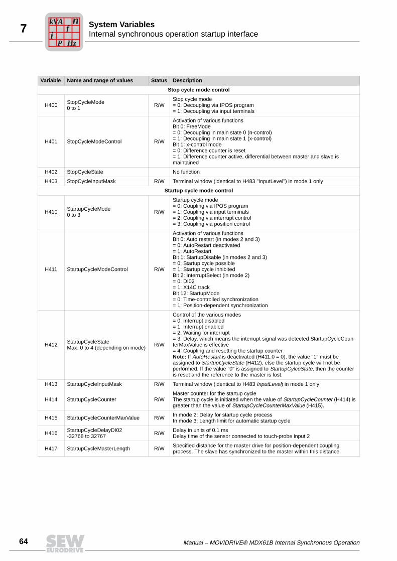
64 Manual – MOVIDRIVE® MDX61B Internal Synchronous Operation
7 Internal synchronous operation startup interfaceSystem Variables
Variable Name and range of values Status Description
Stop cycle mode control
H400 StopCycleMode0 to 1 R/W
Stop cycle mode= 0: Decoupling via IPOS program= 1: Decoupling via input terminals
H401 StopCycleModeControl R/W
Activation of various functionsBit 0: FreeMode= 0: Decoupling in main state 0 (n-control)= 1: Decoupling in main state 1 (x-control)Bit 1: x-control mode= 0: Difference counter is reset= 1: Difference counter active, differential between master and slave is maintained
H402 StopCycleState No function
H403 StopCycleInputMask R/W Terminal window (identical to H483 "InputLevel") in mode 1 only
Startup cycle mode control
H410 StartupCycleMode0 to 3 R/W
Startup cycle mode= 0: Coupling via IPOS program= 1: Coupling via input terminals= 2: Coupling via interrupt control= 3: Coupling via position control
H411 StartupCycleModeControl R/W
Activation of various functionsBit 0: Auto restart (in modes 2 and 3)= 0: AutoRestart deactivated= 1: AutoRestartBit 1: StartupDisable (in modes 2 and 3)= 0: Startup cycle possible= 1: Startup cycle inhibitedBit 2: InterruptSelect (in mode 2)= 0: DI02= 1: X14C trackBit 12: StartupMode= 0: Time-controlled synchronization= 1: Position-dependent synchronization
H412 StartupCycleStateMax. 0 to 4 (depending on mode) R/W
Control of the various modes= 0: Interrupt disabled= 1: Interrupt enabled= 2: Waiting for interrupt= 3: Delay, which means the interrupt signal was detected StartupCycleCoun-terMaxValue is effective= 4: Coupling and resetting the startup counterNote: If AutoRestart is deactivated (H411.0 = 0), the value "1" must be assigned to StartupCycleState (H412), else the startup cycle will not be performed. If the value "0" is assigned to StartupCylceState, then the counter is reset and the reference to the master is lost.
H413 StartupCycleInputMask R/W Terminal window (identical to H483 InputLevel) in mode 1 only
H414 StartupCycleCounter R/WMaster counter for the startup cycleThe startup cycle is initiated when the value of StartupCycleCounter (H414) is greater than the value of StartupCycleCounterMaxValue (H415).
H415 StartupCycleCounterMaxValue R/W In mode 2: Delay for startup cycle processIn mode 3: Length limit for automatic startup cycle
H416 StartupCycleDelayDI02-32768 to 32767 R/W Delay in units of 0.1 ms
Delay time of the sensor connected to touch-probe input 2
H417 StartupCycleMasterLength R/W Specified distance for the master drive for position-dependent coupling process. The slave has synchronized to the master within this distance.
Pi
fkVA
Hz
n
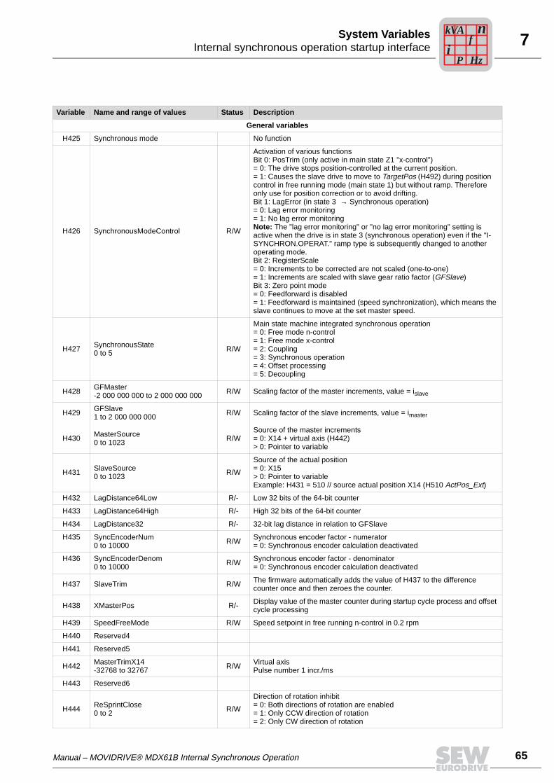
Manual – MOVIDRIVE® MDX61B Internal Synchronous Operation 65
7Internal synchronous operation startup interfaceSystem Variables
Variable Name and range of values Status Description
General variables
H425 Synchronous mode No function
H426 SynchronousModeControl R/W
Activation of various functionsBit 0: PosTrim (only active in main state Z1 "x-control")= 0: The drive stops position-controlled at the current position.= 1: Causes the slave drive to move to TargetPos (H492) during position control in free running mode (main state 1) but without ramp. Therefore only use for position correction or to avoid drifting.Bit 1: LagError (in state 3 → Synchronous operation)= 0: Lag error monitoring= 1: No lag error monitoringNote: The "lag error monitoring" or "no lag error monitoring" setting is active when the drive is in state 3 (synchronous operation) even if the "I-SYNCHRON.OPERAT." ramp type is subsequently changed to another operating mode.Bit 2: RegisterScale= 0: Increments to be corrected are not scaled (one-to-one)= 1: Increments are scaled with slave gear ratio factor (GFSlave)Bit 3: Zero point mode= 0: Feedforward is disabled= 1: Feedforward is maintained (speed synchronization), which means the slave continues to move at the set master speed.
H427 SynchronousState0 to 5 R/W
Main state machine integrated synchronous operation= 0: Free mode n-control= 1: Free mode x-control= 2: Coupling= 3: Synchronous operation= 4: Offset processing= 5: Decoupling
H428 GFMaster-2 000 000 000 to 2 000 000 000 R/W Scaling factor of the master increments, value = islave
H429 GFSlave1 to 2 000 000 000 R/W Scaling factor of the slave increments, value = imaster
H430 MasterSource0 to 1023 R/W
Source of the master increments= 0: X14 + virtual axis (H442)> 0: Pointer to variable
H431 SlaveSource0 to 1023 R/W
Source of the actual position= 0: X15> 0: Pointer to variableExample: H431 = 510 // source actual position X14 (H510 ActPos_Ext)
H432 LagDistance64Low R/- Low 32 bits of the 64-bit counter
H433 LagDistance64High R/- High 32 bits of the 64-bit counter
H434 LagDistance32 R/- 32-bit lag distance in relation to GFSlave
H435 SyncEncoderNum0 to 10000 R/W Synchronous encoder factor - numerator
= 0: Synchronous encoder calculation deactivated
H436 SyncEncoderDenom0 to 10000 R/W Synchronous encoder factor - denominator
= 0: Synchronous encoder calculation deactivated
H437 SlaveTrim R/W The firmware automatically adds the value of H437 to the difference counter once and then zeroes the counter.
H438 XMasterPos R/- Display value of the master counter during startup cycle process and offset cycle processing
H439 SpeedFreeMode R/W Speed setpoint in free running n-control in 0.2 rpm
H440 Reserved4
H441 Reserved5
H442 MasterTrimX14-32768 to 32767 R/W Virtual axis
Pulse number 1 incr./ms
H443 Reserved6
H444 ReSprintClose0 to 2 R/W
Direction of rotation inhibit= 0: Both directions of rotation are enabled= 1: Only CCW direction of rotation= 2: Only CW direction of rotation
Pi
fkVA
Hz
n
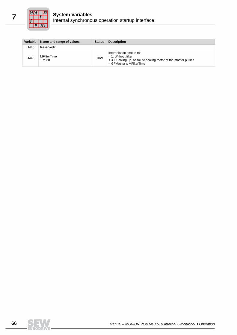
66 Manual – MOVIDRIVE® MDX61B Internal Synchronous Operation
7 Internal synchronous operation startup interfaceSystem Variables
H445 Reserved7
H446 MFilterTime1 to 30 R/W
Interpolation time in ms= 1: Without filter≤ 30: Scaling up, absolute scaling factor of the master pulses= GFMaster x MFilterTime
Variable Name and range of values Status Description
Pi
fkVA
Hz
n
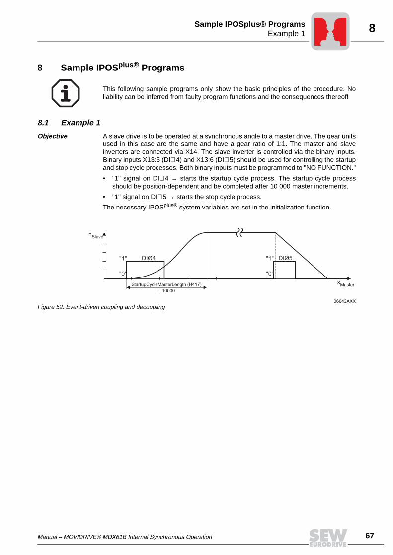
Manual – MOVIDRIVE® MDX61B Internal Synchronous Operation 67
8Example 1Sample IPOSplus® Programs
8 Sample IPOSplus® Programs
8.1 Example 1
Objective A slave drive is to be operated at a synchronous angle to a master drive. The gear unitsused in this case are the same and have a gear ratio of 1:1. The master and slaveinverters are connected via X14. The slave inverter is controlled via the binary inputs.Binary inputs X13:5 (DI∅ 4) and X13:6 (DI∅ 5) should be used for controlling the startupand stop cycle processes. Both binary inputs must be programmed to "NO FUNCTION."
• "1" signal on DI∅ 4 → starts the startup cycle process. The startup cycle processshould be position-dependent and be completed after 10 000 master increments.
• "1" signal on DI∅ 5 → starts the stop cycle process.
The necessary IPOSplus® system variables are set in the initialization function.
This following sample programs only show the basic principles of the procedure. Noliability can be inferred from faulty program functions and the consequences thereof!
06643AXXFigure 52: Event-driven coupling and decoupling
nSlave
xMaster
"1"
"0"
"1"
"0"
DIØ4 DIØ5
StartupCycleMasterLength (H417)
= 10000
68 Manual – MOVIDRIVE® MDX61B Internal Synchronous Operation
8 Example 1Sample IPOSplus® Programs
IPOSplus® program
/*=============================================================================
IPOS source file
for Synchronous Drive Control
SEW-EURODRIVE GmbH & Co KG
Ernst-Blickle-Str. 42
D76646 Bruchsal
http://www.SEW-EURODRIVE.de
===============================================================================*/
#pragma var 300 309
#pragma globals 310 349
#include <const.h>
#include <Example01.h> // Header file with
// variable designations
// and initialization function
*/============================================================================
Main function (IPOS start function)
===============================================================================*/
main ()
*/---------------------------------------------------------
Startup
----------------------------------------------------------*/
InitSynchronization(); //Call up initialization function
/*---------------------------------------------------------
Main program loop
-----------------------------------------------------------*/
while(1)

Manual – MOVIDRIVE® MDX61B Internal Synchronous Operation 69
8Example 1Sample IPOSplus® Programs
Header file with variable designation
/*****************************************************************************
Example01.h
Data and startup header file for IPOS+ Compiler.
For Startup after power on call "InitSynchronization();"
Data file Movidrive Synchronous Drive Control Version 1.0
*****************************************************************************/
#define SynchronousMode H425
#define SynchronousModeControl H426
#define SynchronousState H427
#define GFMaster H428
#define GFSlave H429
#define MasterSource H430
#define Reserved1 H431
#define LagDistance64Low H432
#define LagDistance64High H433
#define LagDistance32 H434
#define Reserved2 H435
#define Reserved3 H436
#define SlaveTrim H437
#define XMasterPos H438
#define SpeedFreeMode H439
#define Reserved4 H440
#define Reserved5 H441
#define MasterTrimX14 H442
#define Reserved6 H443
#define ReSprintClose H444
#define Reserved7 H445
#define MFilterTime H446
// variables for StartupCycle, StopCycle and OffsetCycle
#define StopCycleMode H400
#define StopCycleModeControl H401
#define StopCycleState H402
#define StopCycleInputMask H403
#define StartupCycleMode H410
#define StartupCycleModeControl H411
#define StartupCycleState H412
#define StartupCycleInputMask H413
#define StartupCycleCounter H414
#define StartupCycleCounterMaxValue H415
#define StartupCycleDelayDI02 H416
#define StartupCycleMasterLength H417

70 Manual – MOVIDRIVE® MDX61B Internal Synchronous Operation
8 Example 1Sample IPOSplus® Programs
#define OffsetCycleMode H360
#define OffsetCycleModeControl H361
#define OffsetCycleState H362
#define OffsetCycleInputMask H363
#define OffsetCycleCounter H364
#define OffsetCycleCounterMaxValue H365
#define OffsetCycleMasterLength H366
#define OffsetCycleValue H367
// variables to Register Control
#define RegisterLoopOut H389
#define RegisterLoopDXDTOut H390
// variables for virtual encoder
#define VEncoderMode H370
#define VEncoderModeControl H371
#define VEncoderState H372
#define VEncoderNSetpoint H373
#define VEncoderNActual H374
#define VEncoderXSetpoint H375
#define VEncoderXActual H376
#define VEncoderdNdT H377
//Startup data from: 08.08.2000 - 16:35:22
InitSynchronization()
for (H0=128; H0<=457; H0++) // Reset variables greater than H128
*H0=0;
_Memorize(MEM_LDDATA);
_Wait(100);
GFMaster = 1; // Evaluation of master increments
GFSlave = 1; // Evaluation of slave increments
MFilterTime = 1; // Processing of master increments w/o filter
StartupCycleMode = 1; // Startup cycle mode 1: Event-driven starting of the coupling process via binary input
StartupCycleInputMask = 16; // Selection of terminal DI04 for startup cycle
StartupCycleMasterLength = 10000; // Length of master travel until startup cycle finished
_BitSet (StartupCycleModeControl, 12); // Selection of "position-dependent startup cycle process"
RegisterLooppDXDTOut = 2; // Limiting of correction mechanism
StopCycleMode = 1; // Stop cycle mode 1: Event-driven starting of the stop cycle process via binary input
StopCycleInputMask = 32; // Selection of terminal DI05 for stop cycle
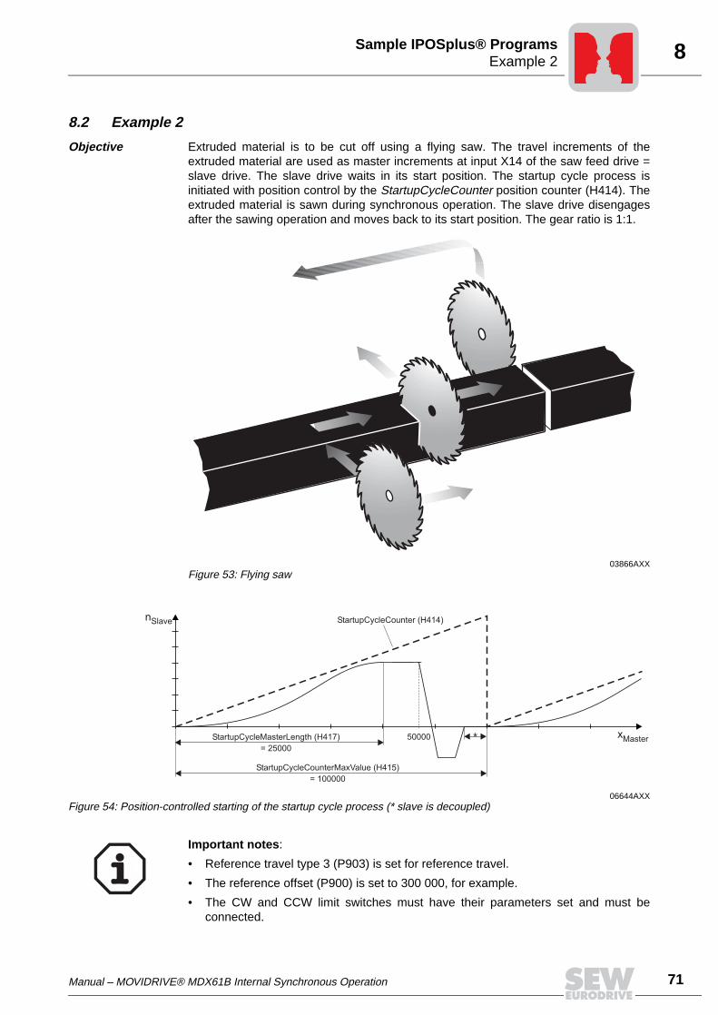
Manual – MOVIDRIVE® MDX61B Internal Synchronous Operation 71
8Example 2Sample IPOSplus® Programs
8.2 Example 2
Objective Extruded material is to be cut off using a flying saw. The travel increments of theextruded material are used as master increments at input X14 of the saw feed drive =slave drive. The slave drive waits in its start position. The startup cycle process isinitiated with position control by the StartupCycleCounter position counter (H414). Theextruded material is sawn during synchronous operation. The slave drive disengagesafter the sawing operation and moves back to its start position. The gear ratio is 1:1.
03866AXXFigure 53: Flying saw
06644AXXFigure 54: Position-controlled starting of the startup cycle process (* slave is decoupled)
nSlave
xMaster
StartupCycleCounterMaxValue (H415)
= 100000
StartupCycleCounter (H414)
*StartupCycleMasterLength (H417)
= 25000
50000
Important notes:
• Reference travel type 3 (P903) is set for reference travel.
• The reference offset (P900) is set to 300 000, for example.
• The CW and CCW limit switches must have their parameters set and must beconnected.
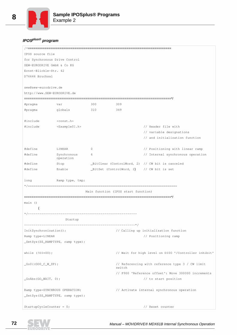
72 Manual – MOVIDRIVE® MDX61B Internal Synchronous Operation
8 Example 2Sample IPOSplus® Programs
IPOSplus® program
/*=============================================================================
IPOS source file
for Synchronous Drive Control
SEW-EURODRIVE GmbH & Co KG
Ernst-Blickle-Str. 42
D76646 Bruchsal
http://www.SEW-EURODRIVE.de
===============================================================================*/
#pragma var 300 309
#pragma globals 310 349
#include <const.h>
#include <Example01.h> // Header file with
// variable designations
// and initialization function
#define LINEAR 0 // Positioning with linear ramp
#define Synchronous operation
6 // Internal synchronous operation
#define Stop _BitClear (ControlWord, 2) // CW bit is canceled
#define Enable _BitSet (ControlWord, 2) // CW bit is set
long Ramp type, tmp;
*/==============================================================================
Main function (IPOS start function)
===============================================================================*/
main ()
*/---------------------------------------------------------
Startup
----------------------------------------------------------*/
InitSynchronization(); // Calling up initialization function
Ramp type=LINEAR // Positioning ramp
_SetSys(SS_RAMPTYPE, ramp type);
while (!DI=00); // Wait for high level on DI00 "/Controller inhibit"
_Go0((GO0_C_W_ZP); // Referencing with reference type 3 / CW limit switch
// P900 "Reference offset": Move 300000 increments
_GoAbs(GO_WAIT, 0); // to start position
Ramp type=SYNCHROUS OPERATION; // Activate internal synchronous operation
_SetSys(SS_RAMPTYPE, ramp type);
StartupCycleCounter = 0; // Reset counter
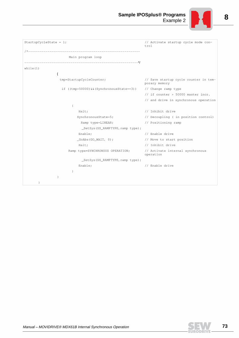
Manual – MOVIDRIVE® MDX61B Internal Synchronous Operation 73
8Example 2Sample IPOSplus® Programs
StartupCycleState = 1; // Activate startup cycle mode con-trol
/*----------------------------------------------------------
Main program loop
-----------------------------------------------------------*/
while(1)
tmp=StartupCycleCounter; // Save startup cycle counter in tem-porary memory
if ((tmp>50000)&&(SynchronousState==3)) // Change ramp type
// if counter > 50000 master incr.
// and drive in synchronous operation
Halt; // Inhibit drive
SynchronousState=5; // Decoupling ( in position control)
Ramp type=LINEAR; // Positioning ramp
_SetSys(SS_RAMPTYPE,ramp type);
Enable; // Enable drive
_GoAbs(GO_WAIT, 0); // Move to start position
Halt; // Inhibit drive
Ramp type=SYNCHRONOUS OPERATION; // Activate internal synchronous operation
_SetSys(SS_RAMPTYPE,ramp type);
Enable; // Enable drive

74 Manual – MOVIDRIVE® MDX61B Internal Synchronous Operation
8 Example 2Sample IPOSplus® Programs
Header file with variable designation
/*****************************************************************************
Example01.h
Data and startup header file for IPOS+ Compiler.
For Startup after power on call "InitSynchronization();"
Data file Movidrive Synchronous Drive Control Version 1.0
*****************************************************************************/
#define SynchronousMode H425
#define SynchronousModeControl H426
#define SynchronousState H427
#define GFMaster H428
#define GFSlave H429
#define MasterSource H430
#define Reserved1 H431
#define LagDistance64Low H432
#define LagDistance64High H433
#define LagDistance32 H434
#define Reserved2 H435
#define Reserved3 H436
#define SlaveTrim H437
#define XMasterPos H438
#define SpeedFreeMode H439
#define Reserved4 H440
#define Reserved5 H441
#define MasterTrimX14 H442
#define Reserved6 H443
#define ReSprintClose H444
#define Reserved7 H445
#define MFilterTime H446
// variables for StartupCycle, StopCycle and OffsetCycle
#define StopCycleMode H400
#define StopCycleModeControl H401
#define StopCycleState H402
#define StopCycleInputMask H403
#define StartupCycleMode H410
#define StartupCycleModeControl H411
#define StartupCycleState H412
#define StartupCycleInputMask H413
#define StartupCycleCounter H414
#define StartupCycleCounterMaxValue H415
#define StartupCycleDelayDI02 H416
#define StartupCycleMasterLength H417

Manual – MOVIDRIVE® MDX61B Internal Synchronous Operation 75
8Example 2Sample IPOSplus® Programs
#define OffsetCycleMode H360
#define OffsetCycleModeControl H361
#define OffsetCycleState H362
#define OffsetCycleInputMask H363
#define OffsetCycleCounter H364
#define OffsetCycleCounterMaxValue H365
#define OffsetCycleMasterLength H366
#define OffsetCycleValue H367
// variables to Register Control
#define RegisterLoopOut H389
#define RegisterLoopDXDTOut H390
// variables for virtual encoder
#define VEncoderMode H370
#define VEncoderModeControl H371
#define VEncoderState H372
#define VEncoderNSetpoint H373
#define VEncoderNActual H374
#define VEncoderXSetpoint H375
#define VEncoderXActual H376
#define VEncoderdNdT H377
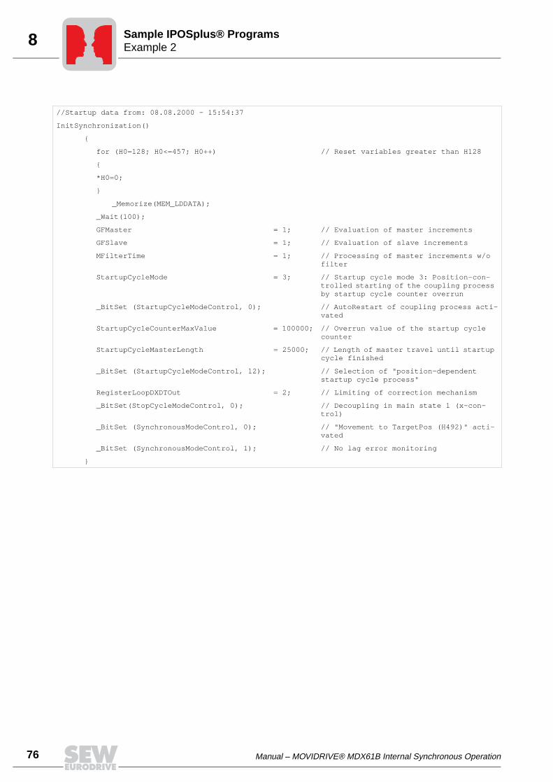
76 Manual – MOVIDRIVE® MDX61B Internal Synchronous Operation
8 Example 2Sample IPOSplus® Programs
//Startup data from: 08.08.2000 - 15:54:37
InitSynchronization()
for (H0=128; H0<=457; H0++) // Reset variables greater than H128
*H0=0;
_Memorize(MEM_LDDATA);
_Wait(100);
GFMaster = 1; // Evaluation of master increments
GFSlave = 1; // Evaluation of slave increments
MFilterTime = 1; // Processing of master increments w/o filter
StartupCycleMode = 3; // Startup cycle mode 3: Position-con-trolled starting of the coupling process by startup cycle counter overrun
_BitSet (StartupCycleModeControl, 0); // AutoRestart of coupling process acti-vated
StartupCycleCounterMaxValue = 100000; // Overrun value of the startup cycle counter
StartupCycleMasterLength = 25000; // Length of master travel until startup cycle finished
_BitSet (StartupCycleModeControl, 12); // Selection of "position-dependent startup cycle process"
RegisterLoopDXDTOut = 2; // Limiting of correction mechanism
_BitSet(StopCycleModeControl, 0); // Decoupling in main state 1 (x-con-trol)
_BitSet (SynchronousModeControl, 0); // "Movement to TargetPos (H492)" acti-vated
_BitSet (SynchronousModeControl, 1); // No lag error monitoring
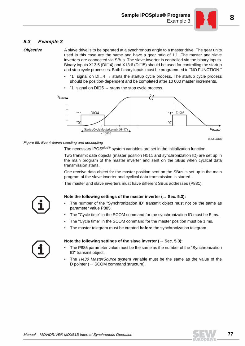
Manual – MOVIDRIVE® MDX61B Internal Synchronous Operation 77
8Example 3Sample IPOSplus® Programs
8.3 Example 3
Objective A slave drive is to be operated at a synchronous angle to a master drive. The gear unitsused in this case are the same and have a gear ratio of 1:1. The master and slaveinverters are connected via SBus. The slave inverter is controlled via the binary inputs.Binary inputs X13:5 (DI∅ 4) and X13:6 (DI∅ 5) should be used for controlling the startupand stop cycle processes. Both binary inputs must be programmed to "NO FUNCTION."
• "1" signal on DI∅ 4 → starts the startup cycle process. The startup cycle processshould be position-dependent and be completed after 10 000 master increments.
• "1" signal on DI∅ 5 → starts the stop cycle process.
The necessary IPOSplus® system variables are set in the initialization function.
Two transmit data objects (master position H511 and synchronization ID) are set up inthe main program of the master inverter and sent on the SBus when cyclical datatransmission starts.
One receive data object for the master position sent on the SBus is set up in the mainprogram of the slave inverter and cyclical data transmission is started.
The master and slave inverters must have different SBus addresses (P881).
06645AXXFigure 55: Event-driven coupling and decoupling
nSlave
"1"
"0"
"1"
"0"
DIØ4 DIØ5
StartupCycleMasterLength (H417)
= 10000
xMasterxMaster
Note the following settings of the master inverter (→ Sec. 5.3):
• The number of the "Synchronization ID" transmit object must not be the same asparameter value P885.
• The "Cycle time" in the SCOM command for the synchronization ID must be 5 ms.
• The "Cycle time" in the SCOM command for the master position must be 1 ms.
• The master telegram must be created before the synchronization telegram.
Note the following settings of the slave inverter (→ Sec. 5.3):
• The P885 parameter value must be the same as the number of the "SynchronizationID" transmit object.
• The H430 MasterSource system variable must be the same as the value of theD pointer (→ SCOM command structure).
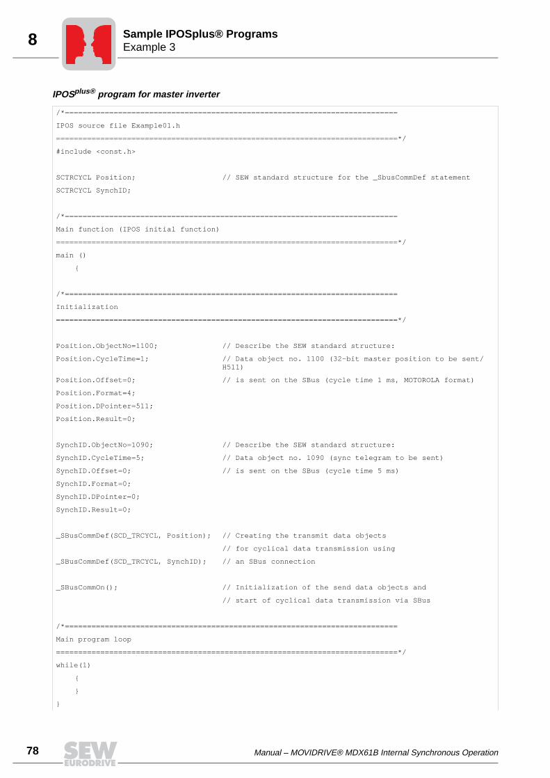
78 Manual – MOVIDRIVE® MDX61B Internal Synchronous Operation
8 Example 3Sample IPOSplus® Programs
IPOSplus® program for master inverter
/*===========================================================================
IPOS source file Example01.h
=============================================================================*/
#include <const.h>
SCTRCYCL Position; // SEW standard structure for the _SbusCommDef statement
SCTRCYCL SynchID;
/*===========================================================================
Main function (IPOS initial function)
=============================================================================*/
main ()
/*===========================================================================
Initialization
=============================================================================*/
Position.ObjectNo=1100; // Describe the SEW standard structure:
Position.CycleTime=1; // Data object no. 1100 (32-bit master position to be sent/H511)
Position.Offset=0; // is sent on the SBus (cycle time 1 ms, MOTOROLA format)
Position.Format=4;
Position.DPointer=511;
Position.Result=0;
SynchID.ObjectNo=1090; // Describe the SEW standard structure:
SynchID.CycleTime=5; // Data object no. 1090 (sync telegram to be sent)
SynchID.Offset=0; // is sent on the SBus (cycle time 5 ms)
SynchID.Format=0;
SynchID.DPointer=0;
SynchID.Result=0;
_SBusCommDef(SCD_TRCYCL, Position); // Creating the transmit data objects
// for cyclical data transmission using
_SBusCommDef(SCD_TRCYCL, SynchID); // an SBus connection
_SBusCommOn(); // Initialization of the send data objects and
// start of cyclical data transmission via SBus
/*===========================================================================
Main program loop
=============================================================================*/
while(1)
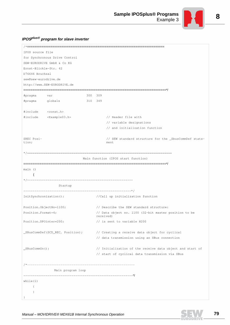
Manual – MOVIDRIVE® MDX61B Internal Synchronous Operation 79
8Example 3Sample IPOSplus® Programs
IPOSplus® program for slave inverter
/*============================================================================
IPOS source file
for Synchronous Drive Control
SEW-EURODRIVE GmbH & Co KG
Ernst-Blickle-Str. 42
D76646 Bruchsal
http://www.SEW-EURODRIVE.de
===============================================================================*/
#pragma var 300 309
#pragma globals 310 349
#include <const.h>
#include <Example03.h> // Header file with
// variable designations
// and initialization function
SREC Posi-tion;
// SEW standard structure for the _SbusCommDef state-ment
*/==============================================================================
Main function (IPOS start function)
===============================================================================*/
main ()
*/---------------------------------------------------------
Startup
----------------------------------------------------------*/
InitSynchronization(); //Call up initialization function
Position.ObjectNo=1100; // Describe the SEW standard structure:
Position.Format=4; // Data object no. 1100 (32-bit master position to be received)
Position.DPOinter=200; // is sent to variable H200
_SBusCommDef(SCD_REC, Position); // Creating a receive data object for cyclical
// data transmission using an SBus connection
_SBusCommOn(); // Initialization of the receive data object and start of
// start of cyclical data transmission via SBus
/*----------------------------------------------------------
Main program loop
-----------------------------------------------------------*/
while(1)
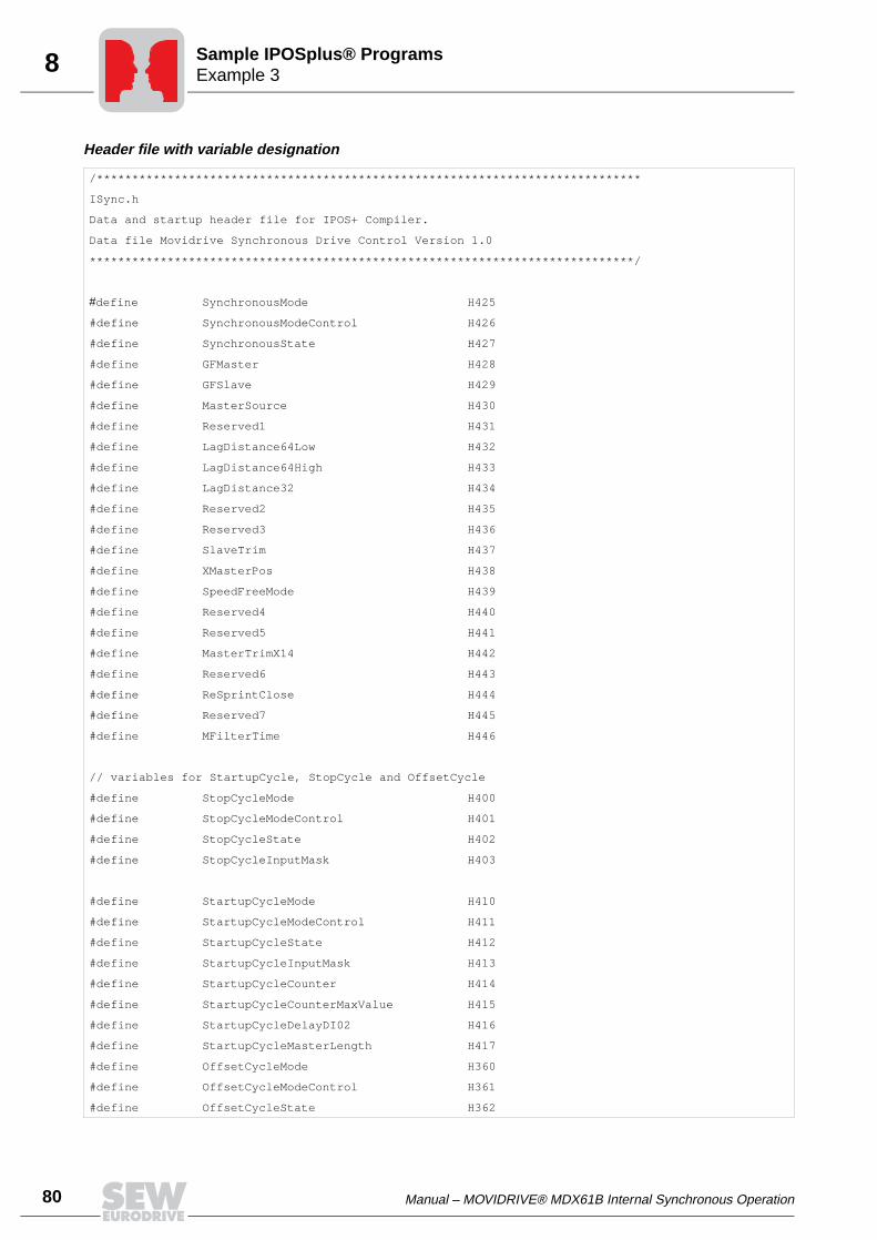
80 Manual – MOVIDRIVE® MDX61B Internal Synchronous Operation
8 Example 3Sample IPOSplus® Programs
Header file with variable designation
/*****************************************************************************
ISync.h
Data and startup header file for IPOS+ Compiler.
Data file Movidrive Synchronous Drive Control Version 1.0
*****************************************************************************/
#define SynchronousMode H425
#define SynchronousModeControl H426
#define SynchronousState H427
#define GFMaster H428
#define GFSlave H429
#define MasterSource H430
#define Reserved1 H431
#define LagDistance64Low H432
#define LagDistance64High H433
#define LagDistance32 H434
#define Reserved2 H435
#define Reserved3 H436
#define SlaveTrim H437
#define XMasterPos H438
#define SpeedFreeMode H439
#define Reserved4 H440
#define Reserved5 H441
#define MasterTrimX14 H442
#define Reserved6 H443
#define ReSprintClose H444
#define Reserved7 H445
#define MFilterTime H446
// variables for StartupCycle, StopCycle and OffsetCycle
#define StopCycleMode H400
#define StopCycleModeControl H401
#define StopCycleState H402
#define StopCycleInputMask H403
#define StartupCycleMode H410
#define StartupCycleModeControl H411
#define StartupCycleState H412
#define StartupCycleInputMask H413
#define StartupCycleCounter H414
#define StartupCycleCounterMaxValue H415
#define StartupCycleDelayDI02 H416
#define StartupCycleMasterLength H417
#define OffsetCycleMode H360
#define OffsetCycleModeControl H361
#define OffsetCycleState H362
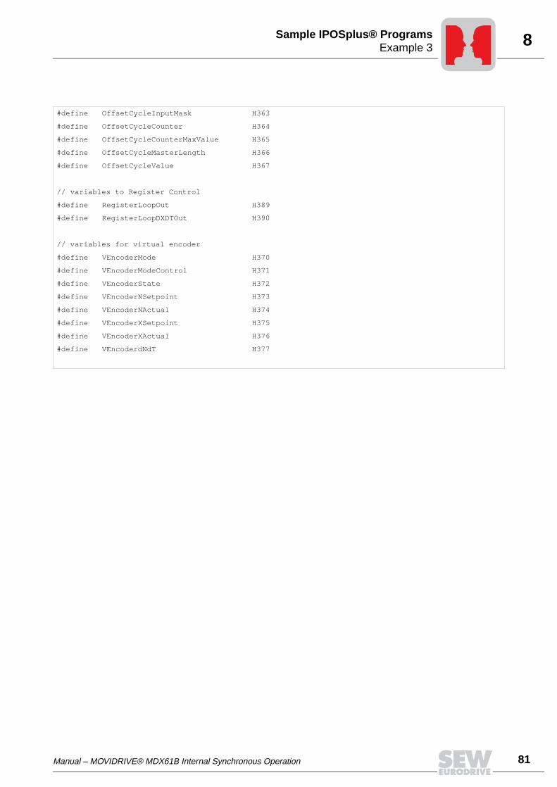
Manual – MOVIDRIVE® MDX61B Internal Synchronous Operation 81
8Example 3Sample IPOSplus® Programs
#define OffsetCycleInputMask H363
#define OffsetCycleCounter H364
#define OffsetCycleCounterMaxValue H365
#define OffsetCycleMasterLength H366
#define OffsetCycleValue H367
// variables to Register Control
#define RegisterLoopOut H389
#define RegisterLoopDXDTOut H390
// variables for virtual encoder
#define VEncoderMode H370
#define VEncoderModeControl H371
#define VEncoderState H372
#define VEncoderNSetpoint H373
#define VEncoderNActual H374
#define VEncoderXSetpoint H375
#define VEncoderXActual H376
#define VEncoderdNdT H377
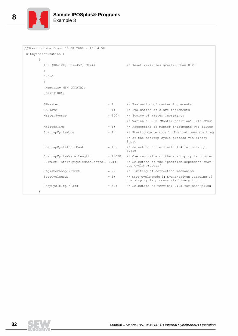
82 Manual – MOVIDRIVE® MDX61B Internal Synchronous Operation
8 Example 3Sample IPOSplus® Programs
//Startup data from: 08.08.2000 - 16:14:58
InitSynchronization()
for (H0=128; H0<=457; H0++) // Reset variables greater than H128
*H0=0;
_Memorize(MEM_LDDATA);
_Wait(100);
GFMaster = 1; // Evaluation of master increments
GFSlave = 1; // Evaluation of slave increments
MasterSource = 200; // Source of master increments:
// Variable H200 "Master position" (via SBus)
MFilterTime = 1; // Processing of master increments w/o filter
StartupCycleMode = 1; // Startup cycle mode 1: Event-driven starting
// of the startup cycle process via binary input
StartupCycleInputMask = 16; // Selection of terminal DI04 for startup cycle
StartupCycleMasterLength = 10000; // Overrun value of the startup cycle counter
_BitSet (StartupCycleModeControl, 12); // Selection of the "position-dependent star-tup cycle process"
RegisterLoopDXDTOut = 2; // Limiting of correction mechanism
StopCycleMode = 1; // Stop cycle mode 1: Event-driven starting of the stop cycle process via binary input
StopCycleInputMask = 32; // Selection of terminal DI05 for decoupling
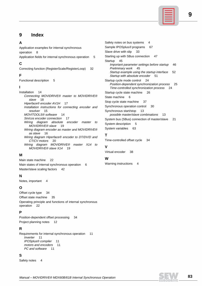
Manual – MOVIDRIVE® MDX60B/61B Internal Synchronous Operation 83
9
9 Index
AApplication examples for internal synchronous
operation 8Application fields for internal synchronous operation 5
CCorrecting function (RegisterScale/RegisterLoop) 32
FFunctional description 5
IInstallation 14
Connecting MOVIDRIVE® master to MOVIDRIVE®slave 18
Hiperface® encoder AV1H 17Installation instructions for connecting encoder and
resolver 15MOVITOOLS® software 14Sin/cos encoder connection 17Wiring diagram absolute encoder master to
MOVIDRIVE® slave 19Wiring diagram encoder as master and MOVIDRIVE®
as slave 16Wiring diagram Hiperface® encoder to DT/DV/D and
CT/CV motors 20Wiring diagram MOVIDRIVE® master X14 to
MOVIDRIVE® slave X14 19
MMain state machine 22
Main states of internal synchronous operation 6Master/slave scaling factors 42
NNotes, important 4
OOffset cycle type 34
Offset state machine 35
Operating principle and functions of internal synchronousoperation 22
PPosition-dependent offset processing 34
Project planning notes 12
RRequirements for internal synchronous operation 11
Inverter 11IPOSplus® compiler 11motors and encoders 11PC and software 11
SSafety notes 4
Safety notes on bus systems 4Sample IPOSplus® programs 67
Slave drive with slip 33
Starting up with SBus connection 47
Startup 45Important parameter settings before startup 46Preliminary work 45Startup example using the startup interface 52Startup with absolute encoder 51
Startup cycle mode control 24Position-dependent synchronization process 25Time-controlled synchronization process 24
Startup cycle state machine 26
State machine 6Stop cycle state machine 37
Synchronous operation control 30
Synchronous start/stop 13possible master/slave combinations 13
System bus (SBus) connection of master/slave 21
System description 5System variables 63
TTime-controlled offset cycle 34
VVirtual encoder 38
WWarning instructions 4

Address List
02/2004
Address ListGermany
HeadquartersProductionSalesService
Bruchsal SEW-EURODRIVE GmbH & Co KGErnst-Blickle-Straße 42 D-76646 BruchsalP.O. BoxPostfach 3023 · D-76642 Bruchsal
Tel. +49 7251 75-0Fax +49 7251 75-1970http://[email protected] Electronics:Tel. +49 171 7210791Service Gear Units and Motors:Tel. +49 172 7601377
AssemblyService
Garbsen (near Hannover)
SEW-EURODRIVE GmbH & Co KGAlte Ricklinger Straße 40-42 D-30823 GarbsenP.O. BoxPostfach 110453 · D-30804 Garbsen
Tel. +49 5137 8798-30Fax +49 5137 [email protected]
Kirchheim (near München)
SEW-EURODRIVE GmbH & Co KGDomagkstraße 5D-85551 Kirchheim
Tel. +49 89 909552-10Fax +49 89 [email protected]
Langenfeld (near Düsseldorf)
SEW-EURODRIVE GmbH & Co KGSiemensstraße 1D-40764 Langenfeld
Tel. +49 2173 8507-30Fax +49 2173 [email protected]
Meerane(near Zwickau)
SEW-EURODRIVE GmbH & Co KGDänkritzer Weg 1D-08393 Meerane
Tel. +49 3764 7606-0Fax +49 3764 [email protected]
Additional addresses for service in Germany provided on request!
France
ProductionSalesService
Haguenau SEW-USOCOME 48-54, route de Soufflenheim B. P. 20185F-67506 Haguenau Cedex
Tel. +33 3 88 73 67 00 Fax +33 3 88 73 66 00http://[email protected]
AssemblySalesService
Bordeaux SEW-USOCOME Parc d’activités de Magellan62, avenue de Magellan - B. P. 182F-33607 Pessac Cedex
Tel. +33 5 57 26 39 00Fax +33 5 57 26 39 09
Lyon SEW-USOCOME Parc d’Affaires RooseveltRue Jacques TatiF-69120 Vaulx en Velin
Tel. +33 4 72 15 37 00Fax +33 4 72 15 37 15
Paris SEW-USOCOME Zone industrielle 2, rue Denis Papin F-77390 Verneuil I’Etang
Tel. +33 1 64 42 40 80Fax +33 1 64 42 40 88
Additional addresses for service in France provided on request!
Algeria
Sales Alger Réducom 16, rue des Frères ZaghnounBellevue El-Harrach16200 Alger
Tel. +213 21 8222-84Fax +213 21 8222-84
Argentina
AssemblySalesService
Buenos Aires SEW EURODRIVE ARGENTINA S.A.Centro Industrial Garin, Lote 35Ruta Panamericana Km 37,51619 Garin
Tel. +54 3327 4572-84Fax +54 3327 [email protected]
Australia
AssemblySalesService
Melbourne SEW-EURODRIVE PTY. LTD.27 Beverage DriveTullamarine, Victoria 3043
Tel. +61 3 9933-1000Fax +61 3 9933-1003http://[email protected]
Sydney SEW-EURODRIVE PTY. LTD.9, Sleigh Place, Wetherill Park New South Wales, 2164
Tel. +61 2 9725-9900Fax +61 2 [email protected]

Address List
02/2004
Austria
AssemblySalesService
Wien SEW-EURODRIVE Ges.m.b.H. Richard-Strauss-Strasse 24A-1230 Wien
Tel. +43 1 617 55 00-0Fax +43 1 617 55 00-30http://[email protected]
Belgium
AssemblySalesService
Brüssel CARON-VECTOR S.A.Avenue Eiffel 5B-1300 Wavre
Tel. +32 10 231-311Fax +32 10 231-336http://[email protected]
Brazil
ProductionSalesService
Sao Paulo SEW-EURODRIVE Brasil Ltda.Avenida Amâncio Gaiolli, 50Caixa Postal: 201-07111-970Guarulhos/SP - Cep.: 07251-250
Tel. +55 11 6489-9133Fax +55 11 6480-3328http://[email protected]
Additional addresses for service in Brazil provided on request!
Bulgaria
Sales Sofia BEVER-DRIVE GMBHBogdanovetz Str.1BG-1606 Sofia
Tel. +359 2 9532565Fax +359 2 [email protected]
Cameroon
Sales Douala Electro-ServicesRue Drouot AkwaB.P. 2024Douala
Tel. +237 4322-99Fax +237 4277-03
Canada
AssemblySalesService
Toronto SEW-EURODRIVE CO. OF CANADA LTD. 210 Walker Drive Bramalea, Ontario L6T3W1
Tel. +1 905 791-1553Fax +1 905 791-2999http://[email protected]
Vancouver SEW-EURODRIVE CO. OF CANADA LTD.7188 Honeyman Street Delta. B.C. V4G 1 E2
Tel. +1 604 946-5535Fax +1 604 [email protected]
Montreal SEW-EURODRIVE CO. OF CANADA LTD.2555 Rue Leger Street LaSalle, Quebec H8N 2V9
Tel. +1 514 367-1124Fax +1 514 [email protected]
Additional addresses for service in Canada provided on request!
Chile
AssemblySalesService
Santiago de Chile
SEW-EURODRIVE CHILE LTDA.Las Encinas 1295Parque Industrial Valle GrandeLAMPARCH-Santiago de ChileP.O. BoxCasilla 23 Correo Quilicura - Santiago - Chile
Tel. +56 2 75770-00Fax +56 2 [email protected]
China
ProductionAssemblySalesService
Tianjin SEW-EURODRIVE (Tianjin) Co., Ltd.No. 46, 7th Avenue, TEDA Tianjin 300457
Tel. +86 22 25322612Fax +86 22 25322611http://www.sew.com.cn
AssemblySalesService
Suzhou SEW-EURODRIVE (Suzhou) Co., Ltd.333, Suhong Middle RoadSuzhou Industrial ParkJiangsu Province, 215021P. R. China
Tel. +86 512 62581781Fax +86 512 [email protected]
Address List
02/2004
Colombia
AssemblySalesService
Bogotá SEW-EURODRIVE COLOMBIA LTDA. Calle 22 No. 132-60Bodega 6, Manzana BSantafé de Bogotá
Tel. +57 1 54750-50Fax +57 1 [email protected]
Croatia
SalesService
Zagreb KOMPEKS d. o. o.PIT Erdödy 4 IIHR 10 000 Zagreb
Tel. +385 1 4613-158Fax +385 1 [email protected]
Czech Republic
Sales Praha SEW-EURODRIVE CZ S.R.O.Business Centrum Praha Luná 591CZ-16000 Praha 6 - Vokovice
Tel. +420 220121234 + 220121236Fax +420 220121237http://[email protected]
Denmark
AssemblySalesService
Kopenhagen SEW-EURODRIVEA/SGeminivej 28-30, P.O. Box 100DK-2670 Greve
Tel. +45 43 9585-00Fax +45 43 9585-09http://[email protected]
Estonia
Sales Tallin ALAS-KUUL ASPaldiski mnt.125EE 0006 Tallin
Tel. +372 6593230Fax +372 6593231
Finland
AssemblySalesService
Lahti SEW-EURODRIVE OYVesimäentie 4FIN-15860 Hollola 2
Tel. +358 3 589-300Fax +358 3 7806-211http://[email protected]
Gabon
Sales Libreville Electro-ServicesB.P. 1889Libreville
Tel. +241 7340-11Fax +241 7340-12
Great Britain
AssemblySalesService
Normanton SEW-EURODRIVE Ltd.Beckbridge Industrial Estate P.O. Box No.1GB-Normanton, West- Yorkshire WF6 1QR
Tel. +44 1924 893-855Fax +44 1924 893-702http://[email protected]
Greece
SalesService
Athen Christ. Boznos & Son S.A.12, Mavromichali StreetP.O. Box 80136, GR-18545 Piraeus
Tel. +30 2 1042 251-34 Fax +30 2 1042 251-59http://[email protected]
Hong Kong
AssemblySalesService
Hong Kong SEW-EURODRIVE LTD.Unit No. 801-806, 8th FloorHong Leong Industrial ComplexNo. 4, Wang Kwong Road Kowloon, Hong Kong
Tel. +852 2 7960477 + 79604654Fax +852 2 [email protected]
Hungary
SalesService
Budapest SEW-EURODRIVE Kft.H-1037 BudapestKunigunda u. 18
Tel. +36 1 437 06-58Fax +36 1 437 [email protected]
Address List
02/2004
India
AssemblySalesService
Baroda SEW-EURODRIVE India Pvt. Ltd.Plot No. 4, GidcPor Ramangamdi · Baroda - 391 243Gujarat
Tel. +91 265 2831021Fax +91 265 [email protected]
Technical Offices Bangalore SEW-EURODRIVE India Private Limited308, Prestige Centre Point7, Edward RoadBangalore
Tel. +91 80 22266565Fax +91 80 [email protected]
Mumbai SEW-EURODRIVE India Private Limited312 A, 3rd Floor, Acme PlazaAndheri Kurla Road, Andheri (E)Mumbai
Tel. +91 22 28348440Fax +91 22 [email protected]
Ireland
SalesService
Dublin Alperton Engineering Ltd. 48 Moyle RoadDublin Industrial EstateGlasnevin, Dublin 11
Tel. +353 1 830-6277Fax +353 1 830-6458
Italy
AssemblySalesService
Milano SEW-EURODRIVE di R. Blickle & Co.s.a.s.Via Bernini,14 I-20020 Solaro (Milano)
Tel. +39 2 96 9801Fax +39 2 96 [email protected]
Ivory Coast
Sales Abidjan SICASte industrielle et commerciale pour l’Afrique165, Bld de MarseilleB.P. 2323, Abidjan 08
Tel. +225 2579-44Fax +225 2584-36
Japan
AssemblySalesService
Toyoda-cho SEW-EURODRIVE JAPAN CO., LTD 250-1, Shimoman-no,Toyoda-cho, Iwata gunShizuoka prefecture, 438-0818
Tel. +81 538 373811Fax +81 538 [email protected]
Korea
AssemblySalesService
Ansan-City SEW-EURODRIVE KOREA CO., LTD. B 601-4, Banweol Industrial Estate Unit 1048-4, Shingil-DongAnsan 425-120
Tel. +82 31 492-8051Fax +82 31 [email protected]
Lebanon
Sales Beirut Gabriel Acar & Fils sarlB. P. 80484Bourj Hammoud, Beirut
Tel. +961 1 4947-86 +961 1 4982-72+961 3 2745-39Fax +961 1 4949-71 [email protected]
Lithuania
Sales Alytus UAB IrsevaMerkines g. 2ALT-4580 Alytus
Tel. +370 315 79204Fax +370 315 [email protected]
Luxembourg
AssemblySalesService
Brüssel CARON-VECTOR S.A.Avenue Eiffel 5B-1300 Wavre
Tel. +32 10 231-311Fax +32 10 231-336http://[email protected]
Malaysia
AssemblySalesService
Johore SEW-EURODRIVE SDN BHD No. 95, Jalan Seroja 39, Taman Johor Jaya81000 Johor Bahru, JohorWest Malaysia
Tel. +60 7 3549409Fax +60 7 [email protected]
Address List
02/2004
Morocco
Sales Casablanca S. R. M.Société de Réalisations Mécaniques 5, rue Emir Abdelkader05 Casablanca
Tel. +212 2 6186-69 + 6186-70 + 6186-71Fax +212 2 [email protected]
Netherlands
AssemblySalesService
Rotterdam VECTOR Aandrijftechniek B.V. Industrieweg 175 NL-3044 AS RotterdamPostbus 10085NL-3004 AB Rotterdam
Tel. +31 10 4463-700Fax +31 10 4155-552http://[email protected]
New Zealand
AssemblySalesService
Auckland SEW-EURODRIVE NEW ZEALAND LTD. P.O. Box 58-428 82 Greenmount driveEast Tamaki Auckland
Tel. +64 9 2745627Fax +64 9 [email protected]
Christchurch SEW-EURODRIVE NEW ZEALAND LTD. 10 Settlers Crescent, FerrymeadChristchurch
Tel. +64 3 384-6251Fax +64 3 [email protected]
Norway
AssemblySalesService
Moss SEW-EURODRIVE A/SSolgaard skog 71N-1599 Moss
Tel. +47 69 241-020Fax +47 69 [email protected]
Peru
AssemblySalesService
Lima SEW DEL PERU MOTORES REDUCTORES S.A.C.Los Calderos <FmSdata>[Idot ] 120-124Urbanizacion Industrial Vulcano, ATE, Lima
Tel. +51 1 3495280Fax +51 1 [email protected]
Poland
AssemblySalesService
Lodz SEW-EURODRIVE Polska Sp.z.o.o.ul. Techniczna 5 PL-92-518 Lodz
Tel. +48 42 67710-90Fax +48 42 67710-99http://[email protected]
Portugal
AssemblySalesService
Coimbra SEW-EURODRIVE, LDA. Apartado 15 P-3050-901 Mealhada
Tel. +351 231 20 9670Fax +351 231 20 3685http://[email protected]
Romania
SalesService
Bucuresti Sialco Trading SRL str. Madrid nr.4 71222 Bucuresti
Tel. +40 21 230-1328Fax +40 21 230-7170 [email protected]
Russia
Sales St. Petersburg ZAO SEW-EURODRIVE P.O. Box 263 RUS-195220 St. Petersburg
Tel. +7 812 5357142 +812 5350430Fax +7 812 [email protected]
Senegal
Sales Dakar SENEMECA Mécanique GénéraleKm 8, Route de Rufisque B.P. 3251, Dakar
Tel. +221 849 47-70Fax +221 849 [email protected]
Serbia and Montenegro
Sales Beograd DIPAR d.o.o.Kajmakcalanska 54SCG-11000 Beograd
Tel. +381 11 3046677Fax +381 11 [email protected]

Address List
02/2004
Singapore
AssemblySalesService
Singapore SEW-EURODRIVE PTE. LTD. No 9, Tuas Drive 2 Jurong Industrial Estate Singapore 638644
Tel. +65 68621701 ... 1705Fax +65 68612827Telex 38 659 [email protected]
Slovakia
Sales Sered SEW-Eurodrive SK s.r.o.Trnavska 920SK-926 01 Sered
Tel. +421 31 7891311Fax +421 31 [email protected]
Slovenia
SalesService
Celje Pakman - Pogonska Tehnika d.o.o.UI. XIV. divizije 14SLO – 3000 Celje
Tel. +386 3 490 83-20Fax +386 3 490 [email protected]
South Africa
AssemblySalesService
Johannesburg SEW-EURODRIVE (PROPRIETARY) LIMITEDEurodrive House Cnr. Adcock Ingram and Aerodrome RoadsAeroton Ext. 2Johannesburg 2013P.O.Box 90004Bertsham 2013
Tel. +27 11 248-7000Fax +27 11 [email protected]
Capetown SEW-EURODRIVE (PROPRIETARY) LIMITED Rainbow ParkCnr. Racecourse & Omuramba RoadMontague GardensCape TownP.O.Box 36556Chempet 7442 Cape Town
Tel. +27 21 552-9820Fax +27 21 552-9830Telex 576 [email protected]
Durban SEW-EURODRIVE (PROPRIETARY) LIMITED2 Monaceo PlacePinetownDurbanP.O. Box 10433, Ashwood 3605
Tel. +27 31 700-3451Fax +27 31 [email protected]
Spain
AssemblySalesService
Bilbao SEW-EURODRIVE ESPAÑA, S.L. Parque Tecnológico, Edificio, 302E-48170 Zamudio (Vizcaya)
Tel. +34 9 4431 84-70Fax +34 9 4431 [email protected]
Sweden
AssemblySalesService
Jönköping SEW-EURODRIVE ABGnejsvägen 6-8S-55303 JönköpingBox 3100 S-55003 Jönköping
Tel. +46 36 3442-00Fax +46 36 3442-80http://[email protected]
Switzerland
AssemblySalesService
Basel Alfred lmhof A.G.Jurastrasse 10 CH-4142 Münchenstein bei Basel
Tel. +41 61 41717-17Fax +41 61 41717-00http://[email protected]
Thailand
AssemblySalesService
Chon Buri SEW-EURODRIVE (Thailand) Ltd.Bangpakong Industrial Park 2700/456, Moo.7, Tambol DonhuarohMuang DistrictChon Buri 20000
Tel. +66 38 454281Fax +66 38 [email protected]
Tunisia
Sales Tunis T. M.S. Technic Marketing Service7, rue Ibn EI Heithem Z.I. SMMT2014 Mégrine Erriadh
Tel. +216 1 4340-64 + 1 4320-29Fax +216 1 4329-76
Address List
02/2004
Turkey
AssemblySalesService
Istanbul SEW-EURODRIVE Hareket Sistemleri Sirketi Bagdat Cad. Koruma Cikmazi No. 3 TR-81540 Maltepe ISTANBUL
Tel. +90 216 4419163 + 216 4419164 + 216 3838014Fax +90 216 [email protected]
USA
ProductionAssemblySalesService
Greenville SEW-EURODRIVE INC. 1295 Old Spartanburg Highway P.O. Box 518Lyman, S.C. 29365
Tel. +1 864 439-7537Fax Sales +1 864 439-7830Fax Manuf. +1 864 439-9948Fax Ass. +1 864 439-0566Telex 805 550 http://[email protected]
AssemblySalesService
San Francisco SEW-EURODRIVE INC. 30599 San Antonio St.Hayward, California 94544-7101
Tel. +1 510 487-3560Fax +1 510 [email protected]
Philadelphia/PA SEW-EURODRIVE INC. Pureland Ind. Complex 2107 High Hill Road, P.O. Box 481Bridgeport, New Jersey 08014
Tel. +1 856 467-2277Fax +1 856 [email protected]
Dayton SEW-EURODRIVE INC.2001 West Main Street Troy, Ohio 45373
Tel. +1 937 335-0036Fax +1 937 [email protected]
Dallas SEW-EURODRIVE INC.3950 Platinum Way Dallas, Texas 75237
Tel. +1 214 330-4824Fax +1 214 [email protected]
Additional addresses for service in the USA provided on request!
Venezuela
AssemblySalesService
Valencia SEW-EURODRIVE Venezuela S.A.Av. Norte Sur No. 3, Galpon 84-319Zona Industrial Municipal NorteValencia, Estado Carabobo
Tel. +58 241 832-9804Fax +58 241 [email protected]@cantv.net


SEW-EURODRIVE GmbH & Co KG · P.O. Box 3023 · D-76642 Bruchsal/Germany
Phone +49 7251 75-0 · Fax +49 7251 75-1970
http://www.sew-eurodrive.com · [email protected]