mounting flange thickness: 5mm
TRANSCRIPT


SCIENTIFIC RESEARCH INSTITUTE FOR PRECISION INSTRUMENTS
A FEDERAL STATE UNITARY ENTERPRISE
APPROVED by: (signed)
V.Shargorodsky, General Designer
June 6, 2002
CryoSat-LRR-01 Laser Retro Reflector Technical Description К01-Э095-00-00 ТО
Moscow 2002

1. INTRODUCTION
1.1. This Technical Description and Operating Manual for CryoSat-LRR-01 Laser Retro Reflector contains information required for study and correct operation of the CryoSat-LRR-01 Laser Retro Reflector.
1.2. Chapter Two hereof presents description and operating principle of the reviewed equipment.
1.3. Chapter Three includes operating instructions.
2. TECHNICAL DESCRIPTION
2.1. PURPOSE
2.1.1. This CryoSat-LRR-01 Laser Retro Reflector is designed to find the range between ground laser stations and the CryoSat satellite as required to determine satellite orbit with high accuracy.
2.2. SPECIFICATIONS
2.2.1. The CryoSat-LRR-01 Laser Retro Reflector enables range finding at the wavelength of 532 nm.
2.2.2. The CryoSat-LRR-01 Laser Retro Reflector supports laser range finding at 20+ deg. angle of position above horizon for all possible bearings.
2.2.3. The range finding correction relative to CryoSat-LRR-01 mounting surface on the spacecraft amounts to +19±6 mm, and depends on the angle of position and the spacecraft bearing relative to station SLR, and shall be added to the measured range.
2.2.4. The location error of CryoSat-LRR-01 equivalent reflex plane relative to the reference point (the centre of the mounting surface) is less than 2 mm.
2.2.5. The CryoSat-LRR-01 Laser Retro Reflector maintains its designed parameters in open space environment.
2.2.6. The CryoSat-LRR-01 Laser Retro Reflector shall remain operational after exposure to mechanical impacts during spacecraft orbital insertion.
2.2.7. The CryoSat-LRR-01 Laser Retro Reflector shall maintain its designed parameters in compliance with the climatic and thermal requirements as specified in Appendix 2 CS-RS-DOR-LR-0001.
2

2.2.8. The mass of the CryoSat-LRR-01 Laser Retro Reflector equals 0.32 kg.
2.2.9. Overall dimensions of the CryoSat-LRR-01 Laser Retro Reflector: ∅ 114 x 51 mm.
2.2.10. Total guaranteed lifetime of the CryoSat-LRR-01 Laser Retro Reflector is 5.5 years.
2.3. COMPLETE DELIVERY SET
2.3.1. The complete delivery set of the described equipment includes:
• CryoSat-LRR-01 Laser Retro Reflector - 1 set; • Technical Description and Operating Manual - 1 copy; • Passport-certificate - 1 copy; • Dimensional Drawing - 1 copy; • Stowing Container - 1 set.
2.4. CryoSat-LRR-01 LASER RETRO REFLECTOR DESIGN AND OPERATION
2.4.1. This CryoSat-LRR-01 Laser Retro Reflector includes seven panel-mounted Laser Reflectors. See Fig. 1 below for the general view and dimensions of the CryoSat-LRR-01 Laser Retro Reflector. The panel is made as a flattened cone with a flange provided in the cone base. The material of the panel and the optical assemblies of the Laser Reflectors is non-magnetic aluminium alloy. Cone flange includes six openings of diameter 5.5 mm designed for attaching the CryoSat-LRR-01 Laser Retro Reflector to the carrying equipment. One Laser Reflector assembly is mounted on the top of the flattened cone; the lateral surface of the cone accommodates six Laser Reflector assemblies fixed by special nuts. To avoid unwanted unscrewing, the fixing nuts are mastic-locked. To minimize thermal distortion of Laser Reflector directivity pattern caused by differing temperature expansion coefficients specific to the Laser Reflector material and the rim material, each of the seven Laser Reflector assemblies incorporates a mechanism designed to normalise the mechanical impacts applied to the Laser Reflector. Laser Reflectors are made of fused quartz with aluminium-coated reflecting prism faces. Where light incidence is normal, the equivalent optical aperture of the Laser Reflector equals ∅ 28.2 mm; the distance between the input face plane and the prism vertex equals 19.1 mm.
3
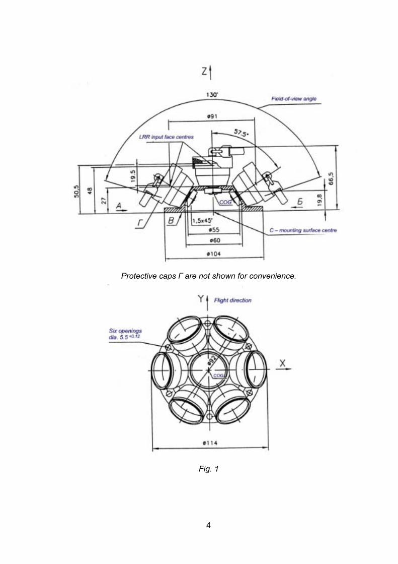
Protective caps Г are not shown for convenience.
Fig. 1
4

The stability of temperature conditions for the CryoSat-LRR-01 Laser Retro Reflector during exposure to open space environment is achieved by applying special thermoregulating white paint AK-512 to all (non-optical) outside surfaces. Red-colour protective caps with FS-01 flags cover all Laser Reflector assemblies.
2.5. CryoSat-LRR-01 LASER RETRO REFLECTOR INTEGRATION
2.5.1. Make sure the requirements of Item 3.3 of the CryoSat-LRR-01 Laser Retro Reflector Operating Manual are strictly followed during equipment integration into the means of delivery.
2.6. MARKING, CONTAINER SEALING AND PACKING
2.6.1. CryoSat-LRR-01 Laser Retro Reflector designation and Serial No. is inscribed on equipment housing. On completion of testing, the equipment placed inside a protective cover is stowed in the Container. The inscriptions �Glass� and �Not to be tipped� are made on the outside of the packing.
5
3. OPERATION MANUAL
3.1. INTRODUCTORY
3.1.1. This Operating Manual is designed to ensure correct operation of the CryoSat-LRR-01 Laser Retro Reflector. The Manual includes information related to CryoSat-LRR-01 Laser Retro Reflector transportation, storage, maintenance and operational readiness. Use additional guidance of the CryoSat-LRR-01 Laser Retro Reflector Technical Description during equipment operation.
3.2. GENERAL INSTRUCTIONS
3.2.1. The Manufacturer supplies this CryoSat-LRR-01 Laser Retro Reflector in the Container designed for equipment transportation and storing.
3.2.2. Personnel shall not be authorized to perform integration and/or operate the Reflector small-size satellite unless properly briefed on this Technical Description and Operating Manual.
3.3. INTEGRATION PROCEDURE
3.3.1. User shall inspect the equipment before commencing any operations on the CryoSat-LRR-01 Laser Retro Reflector. Any premises intended for visual inspection of the CryoSat-LRR-01 Laser Retro Reflector shall protect the equipment against atmospheric effects and shall provide for max. 80 percent relative humidity at +15oC through +35oC.
3.3.2. To inspect this CryoSat-LRR-01 Laser Retro Reflector visually, remove the equipment from the Container, and remove the red-colour process caps from the Laser Reflectors. Make sure to wear cotton gloves at all times while handling this CryoSat-LRR-01 Laser Retro Reflector.
6

Wear cotton gloves to remove tightly mounted process caps carrying FS-01 flags with care; hold the CryoSat-LRR-01 Laser Retro Reflector with hands at the base of the housing to which the Laser Reflector assemblies are attached.
3.3.4. Inspect the CryoSat-LRR-01 Laser Retro Reflector visually; make sure to check the equipment for: 1) optical component chipping; 2) mechanical damage; 3) metal surface corrosion indications; 4) mudding.
3.3.5. Where dust, mud or fatty spots are identified on the input faces of the optical components, make sure to clean the optics by using guidance of the Appendix hereto.
3.3.6. Re-install red-colour process caps with FS-01 flags on Laser Reflector assemblies on completion of the CryoSat-LRR-01 Laser Retro Reflector handling operations.
Attention! Make sure all red-colour process caps with FS-01 flags are removed before nose cone is rolled on after this CryoSat-LRR-01 Laser Retro Reflector has been integrated into the spacecraft. Wear cotton gloves to remove tightly mounted caps with care; hold the CryoSat-LRR-01 Laser Retro Reflector with hands at the base of the panel housing to which the Laser Reflector assemblies are attached.
3.4. STORING REQUIREMENTS
3.4.1. Store this CryoSat-LRR-01 Laser Retro Reflector at storage facilities in Manufacturer-supplied Stowing Container at +5oC through +35oC, 80 percent relative humidity. No vapour of acids, alkali or any different aggressive agent shall be tolerated in the storing environment.
3.5. RULES OF TRANSPORTATION
3.5.1. Make sure this CryoSat-LRR-01 Laser Retro Reflector is transported inside Manufacturer-supplied Stowing Container specially designed to properly protect the equipment against outside mechanical impacts, penetration of moist and/or dust. This equipment can be hauled by any means of transport, at any distance or speed specified for the carrying means, at ambient temperature between minus 50oC through +50oC. Do not keep this equipment in the means of transportation for more than one month within the mentioned temperature range.
7
8
Attention! It is prohibited to drop, tilt and/or shock this CryoSat-LRR-01 Laser Retro Reflector packed in the Container during loading, haulage or unloading operations.
APPENDIX
OPTICS CLEANING INSTRUCTIONS
Clean outer surfaces of the optical components as required to remove fatty spots, traces of moist, dust or any different mudding of the optical surfaces. Make sure to wash hands with soap and wipe hands dry before doing the cleaning. Wear cotton gloves to perform the following sequence: 1) use squirrel fur brush or dry air to remove dust or any different easily removable
mudding; 2) use cambric napkin or purified cotton tampon wrapped around the opposite tip
of the squirrel fur brush to clean fatty contamination. Wrap cotton as follows: dip the opposite tip of the brush in alcohol, insert tip in cotton and rotate brush. To avoid scratching the optical surfaces, make sure the tip is properly wrapped in cotton. Finally, soak cotton in alcohol before cleaning;
3) clean optical surfaces in circular motion, from centre to edge, by pressing slightly to exclude damage. Change tampons from time to time, making sure not to use mudded tampons;
4) use rectified ethyl alcohol of premium quality to clean the optics. Never apply hydrolytic alcohol for danger of oily stains on optical surfaces.


AGREED with (signed) O.Golubovsky Deputy General Designer, QA Dept Head May 24, 2002
APPROVED by:(signed)
V.Shargorodsky,
General Designer
May 26, 2002
TEST REPORT April 04, 2002 N 1403-116 1. TEST ARTICLE: CryoSat Laser Retro Reflector LRR-01 К01-Э095-00-00. 2. TEST OBJECTIVE: Check of compliance with technical specifications L1-4719,
L1-5841, L1-4718 Annex2 of CS-RS-DOR-LR-0001. 3. TEST PROGRAM: according to section 5.2.2.3, 5.2.2.4, 5.2.2.5 Annex 2 of CS-
RS-DOR-LR-0001. 3.1. Sine vibration levels
5 � 20 Hz 20 � 50 Hz 50 � 600 Hz 600 � 2000 Hz 1 �1.7 g 1.7 �3 g 3 �10 g 10 �12 g 3 axes, duration 4 min along each axis.
3.2. Random vibration levels 20 � 100 Hz 100 � 400 Hz 400 � 2000 Hz Perpendicular 6 dB/octave 0.17 g2/Hz -6 dB/octave Lateral 6 dB/octave 0.17 g2/Hz -6 dB/octave 3 axes, duration 2 min along each axis with spectrogram registration for resonance search.
3.3. Shocks 3 shocks +/- 200 g with pulse duration 0.5 ms along each axis.
3.4. Sine resonance search 5 � 2000 Hz 2 g To be performed during 2 min prior and after tests 3.1, 3.2 and 3.3.
4. TEST EQUIPMENT AND INSTRUMENTATION 4.1. Vibroshaker УВЭ-100/5-3000. 4.2. Shock bench СТТ-400/500. 4.3. Supporting frame N 485619.

5. TEST RESULTS Allocation of accelerometers and sine resonance curves are shown in Annex 1and 2 correspondingly. Resonance spikes in a frequency range from 1 650 to 1 850 Hz were revealed along all 3 axes during sine vibration tests (3.1), however amplitudes did not exceed doubled amplitude of the control accelerometer. No changes discovered in spectrograms recorded prior and after each mechanical test according 3.4. Visual inspection also revealed no changes after each mechanical test. Hold-down pressure in all retro reflector�s supports remained unchanged and complaint with design specification.
6. CONCLUSION Laser Retro Reflector LRR-01 К01-Э095-00-00 had passed the tests specified in section 3 without anomalies. Head of Test Division signed I.V.VASSILETZ Test operators signed L.E.BIRYUKOVA
A.S.ILLARIONOV Ye.A.NIKOLAYEV T.I.KHOROSHEVA
Annex 1

Annex 2 Sine resonance curves before and after sine vibration
Sine resonance prior testing Sine resonance after testing

Resonance curves before and after random vibration
Along XX axis Along YY axis Along ZZ axis

CryoSat-LRR-01 стр. 1
№ 1, 17,5 сек (arcseconds)
№ 2, 16,1 сек
№ 3, 15,9 сек

CryoSat-LRR-01 стр. 2
№ 4, 14,1 сек
№ 5, 14,0 сек
№ 6, 14,4 сек

CryoSat-LRR-01 стр. 4
№ 7, 14,5 сек
№ 7 № 6
№ 2 № 1 № 3
№ 5 № 4