motorcycle service manual - bazzazsupport.bazzaz.net/service_manuals/zx636b1_b2.pdf · ninja zx-6r...
TRANSCRIPT

Ninja ZX–6RNinja ZX-6RR
MotorcycleService Manual

This quick reference guide will assistyou in locating a desired topic or pro-cedure.•Bend the pages back to match theblack tab of the desired chapter num-ber with the black tab on the edge ateach table of contents page.•Refer to the sectional table of contentsfor the exact pages to locate the spe-cific topic required.
Quick Reference Guide
General Information 1 j
Periodic Maintenance 2 j
Fuel System (DFI) 3 j
Cooling System 4 j
Engine Top End 5 j
Clutch 6 j
Engine Lubrication System 7 j
Engine Removal/Installation 8 j
Crankshaft / Transmission 9 j
Wheels / Tires 10 j
Final Drive 11 j
Brakes 12 j
Suspension 13 j
Steering 14 j
Frame 15 j
Electrical System 16 j
Appendix 17 j


Ninja ZX-6RNinja ZX-6RR
MotorcycleService Manual
All rights reserved. No parts of this publication may be reproduced, stored in a retrieval system, ortransmitted in any form or by any means, electronic mechanical photocopying, recording or otherwise,without the prior written permission of Quality Assurance Department/Consumer Products & MachineryCompany/Kawasaki Heavy Industries, Ltd., Japan.No liability can be accepted for any inaccuracies or omissions in this publication, although every possible
care has been taken to make it as complete and accurate as possible.The right is reserved to make changes at any time without prior notice and without incurring an obligation
to make such changes to products manufactured previously. See your Motorcycle dealer for the latestinformation on product improvements incorporated after this publication.All information contained in this publication is based on the latest product information available at the time
of publication. Illustrations and photographs in this publication are intended for reference use only and maynot depict actual model component parts.
© 2002 Kawasaki Heavy Industries, Ltd. Third Edition (1): Sep. 30, 2003 (K)

LIST OF ABBREVIATIONSA ampere(s) lb pound(s)
ABDC after bottom dead center m meter(s)
AC alternating current min minute(s)
ATDC after top dead center N newton(s)
BBDC before bottom dead center Pa pascal(s)
BDC bottom dead center PS horsepower
BTDC before top dead center psi pound(s) per square inch
°C degree(s) Celsius r revolution
DC direct current rpm revolution(s) per minute
F farad(s) TDC top dead center
°F degree(s) Fahrenheit TIR total indicator reading
ft foot, feet V volt(s)
g gram(s) W watt(s)
h hour(s) Ω ohm(s)
L liter(s)
Read OWNER’S MANUAL before operating.

Foreword
This manual is designed primarily for use bytrained mechanics in a properly equipped shop.However, it contains enough detail and basic in-formation to make it useful to the owner who de-sires to perform his own basic maintenance andrepair work. A basic knowledge of mechanics,the proper use of tools, and workshop proce-dures must be understood in order to carry outmaintenance and repair satisfactorily. When-ever the owner has insufficient experience ordoubts his ability to do the work, all adjust-ments, maintenance, and repair should be car-ried out only by qualified mechanics.In order to perform the work efficiently and
to avoid costly mistakes, read the text, thor-oughly familiarize yourself with the proceduresbefore starting work, and then do the work care-fully in a clean area. Whenever special tools orequipment are specified, do not use makeshifttools or equipment. Precision measurementscan only be made if the proper instruments areused, and the use of substitute tools may ad-versely affect safe operation.For the duration of the warranty period,
we recommend that all repairs and scheduledmaintenance be performed in accordance withthis service manual. Any owner maintenance orrepair procedure not performed in accordancewith this manual may void the warranty.To get the longest life out of your vehicle:
• Follow the Periodic Maintenance Chart in theService Manual.
• Be alert for problems and non-scheduledmaintenance.
•Use proper tools and genuine Kawasaki Mo-torcycle parts. Special tools, gauges, andtesters that are necessary when servicingKawasaki motorcycles are introduced by theSpecial Tool Catalog or Manual. Genuineparts provided as spare parts are listed in theParts Catalog.
• Follow the procedures in this manual care-fully. Don’t take shortcuts.
•Remember to keep complete records of main-tenance and repair with dates and any newparts installed.
How to Use This ManualIn this manual, the product is divided into its
major systems and these systems make up themanual’s chapters.The Quick Reference Guide shows you all
of the product’s system and assists in locatingtheir chapters. Each chapter in turn has its owncomprehensive Table of Contents.For example, if you want ignition coil informa-
tion, use the Quick Reference Guide to locatethe Electrical System chapter. Then, use theTable of Contents on the first page of the chap-ter to find the ignition coil section.

Whenever you see these WARNING andCAUTION symbols, heed their instructions!Always follow safe operating and maintenancepractices.
WARNINGThis warning symbol identifies specialinstructions or procedures which, if notcorrectly followed, could result in per-sonal injury, or loss of life.
CAUTION
This caution symbol identifies specialinstructions or procedures which, if notstrictly observed, could result in dam-age to or destruction of equipment.
This manual contains four more symbols (inaddition toWARNING andCAUTION) which willhelp you distinguish different types of informa-tion.
NOTEThis note symbol indicates points of par-ticular interest for more efficient and con-venient operation.
• Indicates a procedural step or work to bedone.Indicates a procedural sub-step or how to dothe work of the procedural step it follows. Italso precedes the text of a NOTE.Indicates a conditional step or what action totake based on the results of the test or inspec-tion in the procedural step or sub-step it fol-lows.
In most chapters an exploded view illustrationof the system components follows the Table ofContents. In these illustrations you will find theinstructions indicating which parts require spec-ified tightening torque, oil, grease or a lockingagent during assembly.

GENERAL INFORMATION 1-1
1General Information
Table of Contents
Before Servicing ..................................................................................................................... 1-2Model Identification................................................................................................................. 1-7General Specifications............................................................................................................ 1-9Technical Information – Air Inlet System ................................................................................ 1-15Technical Information – New Ignition Interlock Sidestand ...................................................... 1-18Technical Information – Tail/Brake Lights Employing LED ..................................................... 1-19Technical Information – KAWASAKI LOW EXHAUST EMISSION SYSTEM ......................... 1-21Unit Conversion Table ............................................................................................................ 1-22
1-2 GENERAL INFORMATION
Before Servicing
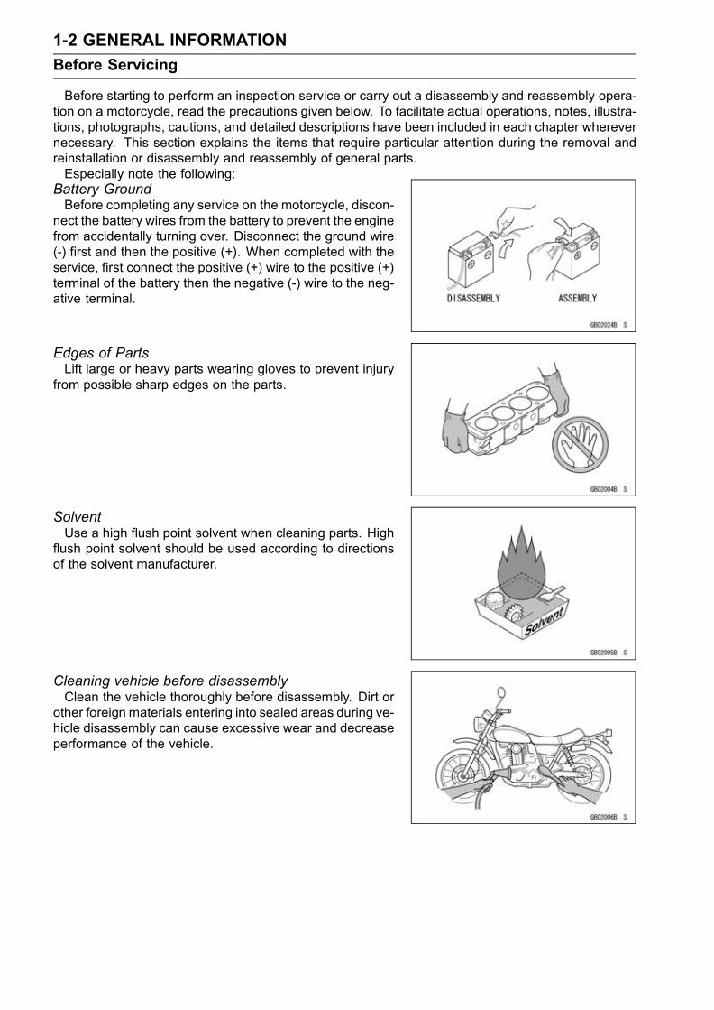
Before starting to perform an inspection service or carry out a disassembly and reassembly opera-tion on a motorcycle, read the precautions given below. To facilitate actual operations, notes, illustra-tions, photographs, cautions, and detailed descriptions have been included in each chapter wherevernecessary. This section explains the items that require particular attention during the removal andreinstallation or disassembly and reassembly of general parts.Especially note the following:
Battery GroundBefore completing any service on the motorcycle, discon-
nect the battery wires from the battery to prevent the enginefrom accidentally turning over. Disconnect the ground wire(-) first and then the positive (+). When completed with theservice, first connect the positive (+) wire to the positive (+)terminal of the battery then the negative (-) wire to the neg-ative terminal.
Edges of PartsLift large or heavy parts wearing gloves to prevent injury
from possible sharp edges on the parts.
SolventUse a high flush point solvent when cleaning parts. High
flush point solvent should be used according to directionsof the solvent manufacturer.
Cleaning vehicle before disassemblyClean the vehicle thoroughly before disassembly. Dirt or
other foreign materials entering into sealed areas during ve-hicle disassembly can cause excessive wear and decreaseperformance of the vehicle.

GENERAL INFORMATION 1-3
Before Servicing
Arrangement and Cleaning of Removed PartsDisassembled parts are easy to confuse. Arrange the
parts according to the order the parts were disassembledand clean the parts in order prior to assembly.
Storage of Removed PartsAfter all the parts including subassembly parts have been
cleaned, store the parts in a clean area. Put a clean clothor plastic sheet over the parts to protect from any foreignmaterials that may collect before re-assembly.
InspectionReuse of worn or damaged parts may lead to serious ac-
cident. Visually inspect removed parts for corrosion, discol-oration, or other damage. Refer to the appropriate sectionsof this manual for service limits on individual parts. Replacethe parts if any damage has been found or if the part is be-yond its service limit.
Replacement PartsReplacement Parts must be KAWASAKI genuine or rec-
ommended by KAWASAKI. Gaskets, O rings, Oil seals,Grease seals, circlips or cotter pins must be replaced withnew ones whenever disassembled.
Assembly OrderIn most cases assembly order is the reverse of disassem-
bly, however, if assembly order is provided in this ServiceManual, follow the procedures given.

1-4 GENERAL INFORMATION
Before Servicing
Tightening SequenceBolts, nuts, or screws must be tightened according to the
specified sequence to prevent case warpage or deformationwhich can lead to malfunction. If the specified tighteningsequence is not indicated, tighten the fasteners alternatingdiagonally. Often, the tightening sequence is followed twice-initial tightening and final tightening with torque wrench.
Tightening TorqueIncorrect torque applied to a bolt, nut, or screw may
lead to serious damage. Tighten fasteners to the specifiedtorque using a good quality torque wrench.
ForceUse common sense during disassembly and assembly,
excessive force can cause expensive or hard to repair dam-age. When necessary, remove screws that have a non-permanent locking agent applied using an impact driver.Use a plastic-faced mallet whenever tapping is necessary.
Gasket, OringHardening, shrinkage, or damage of both gaskets
and O-rings after disassembly can reduce sealing per-formance. Remove old gaskets and clean the sealingsurfaces thoroughly so that no gasket material or othermaterial remains. Install new gaskets and replace usedO-rings when re-assembling
Liquid Gasket, Locking AgentFor applications that require Liquid Gasket or a Locking
agent, clean the surfaces so that no oil residue remains be-fore applying liquid gasket or locking agent. Do not applythem excessively. Excessive application can clog oil pas-sages and cause serious damage.

GENERAL INFORMATION 1-5
Before Servicing
PressFor items such as bearings or oil seals that must be
pressed into place, apply small amount of oil to the con-tact area. Be sure to maintain proper alignment and usesmooth movements when installing.
Ball Bearing and Needle BearingDo not remove pressed ball or needle unless removal is
absolutely necessary. Replace with new ones wheneverremoved. Press bearings with the manufacturer and sizemarks facing out. Press the bearing into place by puttingpressure on the correct bearing race as shown.Pressing the incorrect race can cause pressure between
the inner and outer race and result in bearing damage.
Oil Seal, Grease SealDo not remove pressed oil or grease seals unless removal
is necessary. Replace with new ones whenever removed.Press new oil seals with manufacture and size marks facingout. Make sure the seal is aligned properly when installing.
Circlips, Cotter PinsReplace circlips or cotter pins that were removed with new
ones. Install the circlip with its sharp edge facing outwardand its chamfered side facing inward to prevent the clip frombeing pushed out of its groove when loaded. Take carenot to open the clip excessively when installing to preventdeformation.
LubricationIt is important to lubricate rotating or sliding parts during
assembly to minimize wear during initial operation. Lubri-cation points are called out throughout this manual, applythe specific oil or grease as specified.

1-6 GENERAL INFORMATION
Before Servicing
Direction of Engine RotationWhen rotating the crankshaft by hand, the free play
amount of rotating direction will affect the adjustment. Ro-tate the crankshaft to positive direction (clockwise viewedfrom output side).
Electrical WiresA two-color wire is identified first by the primary color and
then the stripe color. Unless instructed otherwise, electricalwires must be connected to those of the same color.
GENERAL INFORMATION 1-7
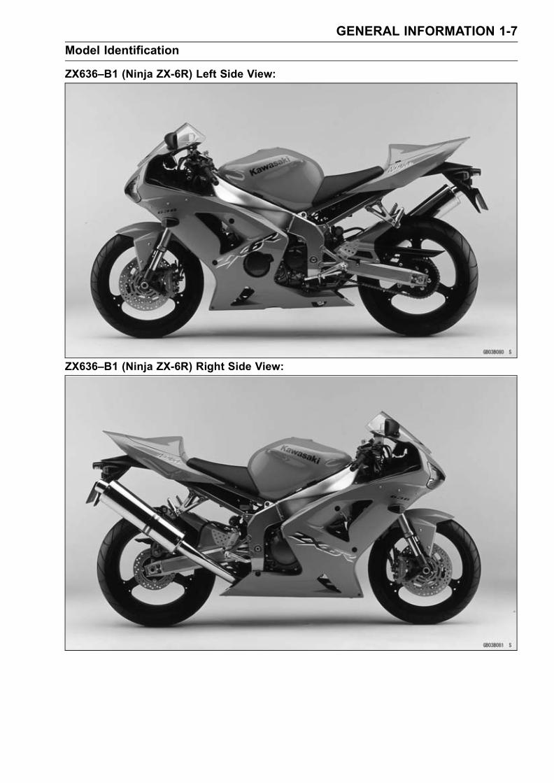
Model Identification
ZX636–B1 (Ninja ZX-6R) Left Side View:
ZX636–B1 (Ninja ZX-6R) Right Side View:
1-8 GENERAL INFORMATION
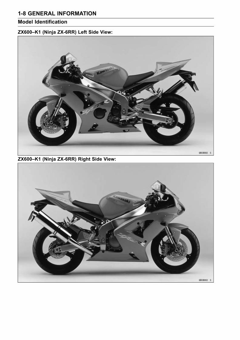
Model Identification
ZX600–K1 (Ninja ZX-6RR) Left Side View:
ZX600–K1 (Ninja ZX-6RR) Right Side View:
GENERAL INFORMATION 1-9
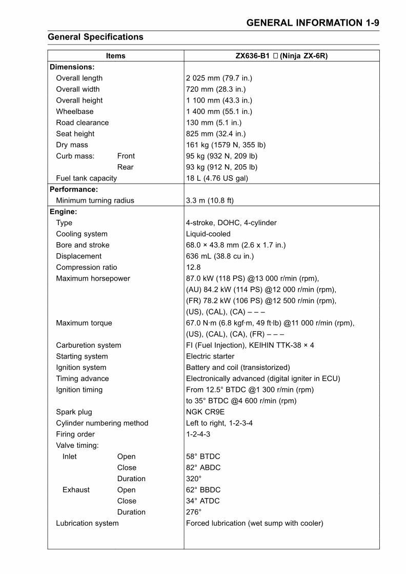
General Specifications
Items ZX636-B1 ∼ (Ninja ZX-6R)Dimensions:
Overall length 2 025 mm (79.7 in.)
Overall width 720 mm (28.3 in.)
Overall height 1 100 mm (43.3 in.)
Wheelbase 1 400 mm (55.1 in.)
Road clearance 130 mm (5.1 in.)
Seat height 825 mm (32.4 in.)
Dry mass 161 kg (1579 N, 355 lb)
Curb mass: Front 95 kg (932 N, 209 lb)
Rear 93 kg (912 N, 205 lb)
Fuel tank capacity 18 L (4.76 US gal)
Performance:
Minimum turning radius 3.3 m (10.8 ft)
Engine:
Type 4-stroke, DOHC, 4-cylinder
Cooling system Liquid-cooled
Bore and stroke 68.0 × 43.8 mm (2.6 x 1.7 in.)
Displacement 636 mL (38.8 cu in.)
Compression ratio 12.8
Maximum horsepower 87.0 kW (118 PS) @13 000 r/min (rpm),
(AU) 84.2 kW (114 PS) @12 000 r/min (rpm),
(FR) 78.2 kW (106 PS) @12 500 r/min (rpm),
(US), (CAL), (CA) – – –
Maximum torque 67.0 N·m (6.8 kgf·m, 49 ft·lb) @11 000 r/min (rpm),
(US), (CAL), (CA), (FR) – – –
Carburetion system FI (Fuel Injection), KEIHIN TTK-38 × 4
Starting system Electric starter
Ignition system Battery and coil (transistorized)
Timing advance Electronically advanced (digital igniter in ECU)
Ignition timing From 12.5° BTDC @1 300 r/min (rpm)
to 35° BTDC @4 600 r/min (rpm)
Spark plug NGK CR9E
Cylinder numbering method Left to right, 1-2-3-4
Firing order 1-2-4-3
Valve timing:
Inlet Open 58° BTDC
Close 82° ABDC
Duration 320°
Exhaust Open 62° BBDC
Close 34° ATDC
Duration 276°
Lubrication system Forced lubrication (wet sump with cooler)

1-10 GENERAL INFORMATION
General Specifications
Items ZX636-B1 ∼ (Ninja ZX-6R)Engine oil:
Type API SE, SF or SG
API SH or SJ with JASO MA
Viscosity SAE10W-40
Capacity 4.0 L (4.2 US qt)
Drive Train:
Primary reduction system:
Type Gear
Reduction ratio 2.022 (89/44)
Clutch type Wet multi disc
Transmission:
Type 6-speed, constant mesh, return shift
Gear ratios:
1st 2.923 (38/13)
2nd 2.055 (37/18)
3rd 1.722 (31/18)
4th 1.450 (29/20)
5th 1.272 (28/22)
6th 1.153 (30/26)
Final drive system:
Type Chain drive
Reduction ratio 2.666 (40/15)
Overall drive ratio 6.223 @Top gear
Frame:
Type Tubular, diamond
Caster (rake angle) 24.5°
Trail 95 mm (3.7 in.)
Front tire: Type Tubeless
Size 120/65 ZR17 M/C (56W)
Rear tire: Type Tubeless
Size 180/55 ZR17 M/C (73W)
Front suspension:
Type Telescopic fork (upside-down)
Wheel travel 120 mm (4.7 in.)
Rear suspension:
Type Swingarm (uni-trak)
Wheel travel 135 mm (5.3 in.)
Brake Type: Front Dual discs
Rear Single disc
Electrical Equipment:
Battery 12 V 8 Ah
Headlight:
Type Semi-sealed beam
Bulb Hi 12 V 55 W (quartz-halogen) × 2

GENERAL INFORMATION 1-11
General Specifications
Items ZX636-B1 ∼ (Ninja ZX-6R)Lo 12 V 55 W (quartz-halogen)
Tail/brake light 12 V 0.5/3.8 W (LED)
(US), (CAL), (CA) 12 V 0.5/5 W (LED)
Alternator: Type Three-phase AC
Rated output 22.5 A / 14 V @5 000 r/min (rpm)
Specifications subject to change without notice, and may not apply to every country.
(US): United States Model
(CAL): California Model
(CA): Canada Model
(AU): Australia Model
(FR): France Model

1-12 GENERAL INFORMATION
General Specifications
Items ZX600-K1 (Ninja ZX-6RR)
Dimensions:
Overall length 2 025 mm (79.7 in.)
Overall width 720 mm (28.3 in.)
Overall height 1 100 mm (43.3 in.)
Wheelbase 1 400 mm (55.1 in.)
Road clearance 130 mm (5.1 in.)
Seat height 825 mm (32.4 in.)
Dry mass 161 kg (1579 N, 355 lb)
Curb mass: Front 95 kg (932 N, 209 lb)
Rear 93 kg (912 N, 205 lb)
Fuel tank capacity 18 L (4.76 US gal)
Performance:
Minimum turning radius 3.3 m (10.8 ft)
Engine:
Type 4-stroke, DOHC, 4-cylinder
Cooling system Liquid-cooled
Bore and stroke 67.0 × 42.5 mm (2.6 x 1.7 in.)
Displacement 599 mL (36.6 cu in.)
Compression ratio 13.0
Maximum horsepower 83.1 kW (113 PS) @13 200 r/min (rpm),
(FR) 78.2 kW (106 PS) @13 000 r/min (rpm),
(US), (CAL), (CA) – – –
Maximum torque 64.4 N·m (6.6 kgf·m, 47.5 ft·lb) @12 000 r/min (rpm),
(US), (CAL), (CA), (FR) – – –
Carburetion system FI (Fuel Injection), KEIHIN TTK-38 × 4
Starting system Electric starter
Ignition system Battery and coil (transistorized)
Timing advance Electronically advanced (digital igniter in ECU)
Ignition timing From 12.5° BTDC @1 300 r/min (rpm)
to 35° BTDC @4 600 r/min (rpm)
Spark plug NGK CR9E
Cylinder numbering method Left to right, 1-2-3-4
Firing order 1-2-4-3
Valve timing:
Inlet Open 55° BTDC
Close 85° ABDC
Duration 320°
Exhaust Open 62° BBDC
Close 34° ATDC
Duration 276°
Lubrication system Forced lubrication (wet sump with cooler)
Engine oil:
Type API SE, SF or SG
API SH or SJ with JASO MA

GENERAL INFORMATION 1-13
General Specifications
Items ZX600-K1 (Ninja ZX-6RR)
Viscosity SAE10W-40
Capacity 4.0 L (4.2 US qt)
Drive Train:
Primary reduction system:
Type Gear
Reduction ratio 2.022 (89/44)
Clutch type Wet multi disc
Transmission:
Type 6-speed, constant mesh, return shift
Gear ratios:
1st 2.923 (38/13)
2nd 2.055 (37/18)
3rd 1.722 (31/18)
4th 1.450 (29/20)
5th 1.272 (28/22)
6th 1.153 (30/26)
Final drive system:
Type Chain drive
Reduction ratio 2.666 (40/15)
Overall drive ratio 6.223 @Top gear
Frame:
Type Tubular, diamond
Caster (rake angle) 24.5°
Trail 95 mm (3.7 in.)
Front tire: Type Tubeless
Size 120/65 ZR17 M/C (56W)
Rear tire: Type Tubeless
Size 180/55 ZR17 M/C (73W)
Front suspension:
Type Telescopic fork (upside-down)
Wheel travel 120 mm (4.7 in.)
Rear suspension:
Type Swingarm (uni-trak)
Wheel travel 135 mm (5.3 in.)
Brake Type: Front Dual discs
Rear Single disc
Electrical Equipment:
Battery 12 V 8 Ah
Headlight:
Type Semi-sealed beam
Bulb Hi 12 V 55 W (quartz-halogen) × 2
Lo 12 V 55 W (quartz-halogen)
Tail/brake light 12 V 0.5/3.8 W (LED)
(US), (CAL), (CA) 12 V 0.5/5 W (LED)

1-14 GENERAL INFORMATION
General Specifications
Items ZX600-K1 (Ninja ZX-6RR)
Alternator: Type Three-phase AC
Rated output 22.5 A / 14 V @5 000 r/min (rpm)
Specifications subject to change without notice, and may not apply to every country.
(US): United States Model
(CAL): California Model
(CA): Canada Model
(FR): France Model
GENERAL INFORMATION 1-15
Technical Information – Air Inlet System
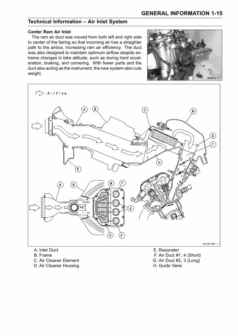
Center Ram Air InletThe ram air duct was moved from both left and right side
to center of the fairing so that incoming air has a straighterpath to the airbox, increasing ram air efficiency. The ductwas also designed to maintain optimum airflow despite ex-treme changes in bike attitude, such as during hard accel-eration, braking, and cornering. With fewer parts and theduct also acting as the instrument, the new system also cutsweight.
A. Inlet DuctB. FrameC. Air Cleaner ElementD. Air Cleaner Housing
E. ResonatorF. Air Duct #1, 4 (Short)G. Air Duct #2, 3 (Long)H. Guide Vane

1-16 GENERAL INFORMATION
Technical Information – Air Inlet System
Subthrottle Control SystemThe ZX636–B1 ∼ and ZX600–K1 utilize large bore throttle bodies to increase power output. How-
ever, sudden changes in throttle opening can cause hesitation and jerky throttle response with a singlebutterfly valve in a large bore. Therefore two throttle valves are placed in each inlet tract, the mainthrottle valve located closest to the cylinder and a subthrottle valve placed further up the inlet tract.The main throttle valve is operated by the rider when the throttle grip is turned, while the subthrot-tle valve is operated by a stepping motor controlled by the ECU. The subthrottle valve automaticallyadjusts air inlet to more precisely match engine demand, so that when the main throttle is openedquickly there is no hesitation or jerky response.The subthrottle valves allow the fuel injection system to provide smooth throttle response, similar to
that of a constant velocity carburetor, no matter how quickly the throttle is opened.
A. Main Throttle ValveB. Subthrottle ValveC. Throttle Valve
D. Vacuum PistonE. Inlet Air

GENERAL INFORMATION 1-17
Technical Information – Air Inlet System
OperationThe subthrottle control system consists of the subthrottle valve, subthrottle valve actuator with a
stepping motor built in it, ECU, and subthrottle sensor. The subthrottle valve is built in the each throttlebody.The subthrottle control system operates on the signal supplied from the ECU. The open/close oper-
ation of the subthrottle valve is performed by the subthrottle actuator which is controlled by the ECUto change the current direction into the motor of the subthrottle valve actuator.The subthrottle sensor detects the subthrottle valve actuator movement by measuring voltage and
the ECU determines the subthrottle valve angle based on the operation map.When turning the ignition switch ON, every time the ECU automatically drives the subthrottle valve
from fully closed position to fully opened position. The ECU memorizes these positions and turnsback the subthrottle valve to the original point to confirm the subthrottle valve idling voltage.
A. Subthrottle ValvesB. Subthrottle Valve ActuatorC. Subthrottle SensorD. Main Throttle Sensor
E. ECU (Electric Control Unit)F. Air Cleaner SideG. Crankshaft SensorH. Speed Sensor

1-18 GENERAL INFORMATION
Technical Information – New Ignition Interlock Sidestand
OutlineThe New Ignition Interlock Sidestand System applied to ZX636–B1 ∼ and ZX600–K1 models that
cannot function if gears are engaged and/or the sidestand is not lifted upward even though clutchlever pulled in, which differs from the traditional one. Refer to the tables below as to the engine startsand/or the driving at each condition.
New Ignition Interlock Sidestand SystemSide Stand Gear Position Clutch Lever Engine Start Engine Run
A Up Neutral Released Starts Continue running
B Up Neutral Pulled in Starts Continue running
C Up In Gear Released Doesn’t start Continue running
D Up In Gear Pulled in Starts Continue running
E Down Neutral Released Starts Continue running
F Down Neutral Pulled in Starts Continue running
G Down In Gear Released Doesn’t start Stops
H Down In Gear Pulled in Doesn’t start Stops
Current Ignition Interlock Sidestand SystemSide Stand Gear Position Clutch Lever Engine Start Engine Run
A Up Neutral Released Starts Continue running
B Up Neutral Pulled in Starts Continue running
C Up In Gear Released Doesn’t start Continue running
D Up In Gear Pulled in Starts Continue running
E Down Neutral Released Starts Continue running
F Down Neutral Pulled in Starts Continue running
G Down In Gear Released Doesn’t start Stops
H Down In Gear Pulled in Start Continue running

GENERAL INFORMATION 1-19
Technical Information – Tail/Brake Lights Employing LED
OutlineThis model employs a tail/brake light containing 21 Light Emitting Diodes (LED). The LED emits
luminous beams over a longer life span than those emitted from a traditional electric heated bulb(more than 5 times longer), uses lower voltage, expends lower wattage (approx.1/5), and is quickerresponsing.
Due Position of LED Installation
The resistors, the diodes, and the Zener diodes aremounted in the electronic circuits [A] of the LED, whichsupplies the steady current and voltage to the light.
Light Emitting Diode (LED)The Light Emitting Diode (LED) [A] is an element of semi-
conductor diode that converts applied voltage to light.
The LED emits luminous beams by the collision of nega-tive charge electrons [A] and positive charge holes [B] whenapplied the forward voltage and current to the PN junctiondiode [C].

1-20 GENERAL INFORMATION
Technical Information – Tail/Brake Lights Employing LED
The emitting color differs according to the materials ofsemi-conductors.
Materials of Semi-Conductor and Emitting Color
Materials of Semi-Conductor Emitting Color
GaAsP,GaAlAs
Red
GaP Green
GaN Blue
Ga: GalliumAs: ArsenicP: PhosphorusN: NitrogenAl: Aluminum

GENERAL INFORMATION 1-21
Technical Information – KAWASAKI LOW EXHAUST EMISSION SYSTEM
Since the emission regulations become more severe, Kawasaki has adopted a type of simplifiedKAWASAKI LOW EXHAUST EMISSION SYSTEM (KLEEN), which have no catalyst protection sys-tem, according to each regulation of different countries.The muffler with built-in catalyst has the same durability as the conventional muffler, however, do
not use leaded gasoline and do not coast with the ignition system OFF. Running the engine withoutignition damages catalyst.Refer to the ZX636A Service Manual (Part No. 99924-1288) for more information about the KLEEN
(theory, maintenance, and handling precautions), including the secondary air injection system.
Honeycomb Type Catalytic ConverterThe converter is a three-way catalytic converter, and its surface is covered with alumina upon whichplatinum and rhodium are applied, and has a cylindrical metallic honeycomb structure made bybending a corrugated sheet and a flat sheet of stainless steel into a spiral of increasing diameter.The honeycomb structure is convenient for the catalytic converter because it has a large surfacearea but small size to react effectively and has low exhaust resistance. In addition, its inherentstrength helps resist vibration, and has simple structure welded directly on the silencer.Generally, the temperature of the exhaust gas must be higher than activation temperature, so theconverters are installed in the exhaust manifold rear end where the temperature of exhaust gas isstill high. And, the converters will be activated even under low load conditions.After the exhaust gas is diluted with the secondary air injection, the catalytic converter works wellbecause of rich oxygen to reduce CO, HC, and NOx. Accordingly, we can keep the exhaust gasemission within regulation.This type of converter works more efficiently as a three-way catalytic converter to reduce CO, HC,and NOx than the pipe type catalytic converter because of its more and denser catalysts.
1. Manifold2. Silencer3. Honeycomb Type Catalyst4. Non-Catalyst (Pipe Type)5. Mark for Manifold6. Mark for Silencer
1-22 GENERAL INFORMATION
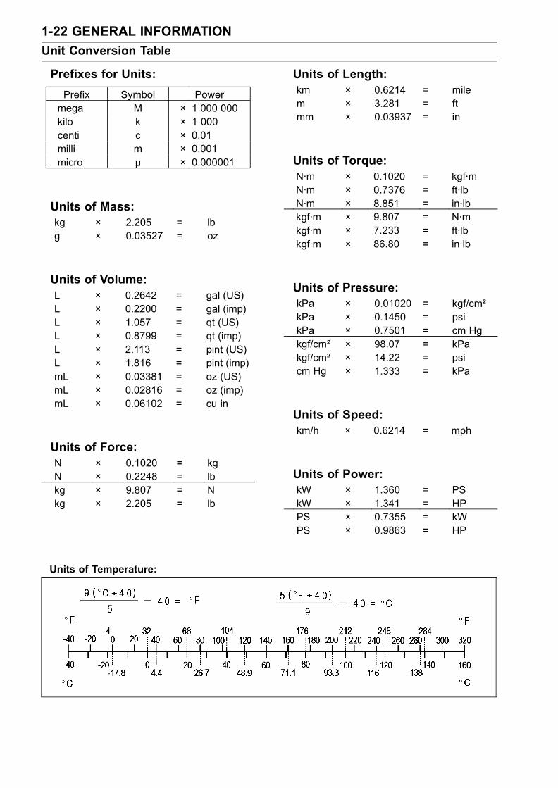
Unit Conversion Table
Prefixes for Units:
Prefix Symbol Powermega M × 1 000 000kilo k × 1 000centi c × 0.01milli m × 0.001micro µ × 0.000001
Units of Mass:kg × 2.205 = lbg × 0.03527 = oz
Units of Volume:L × 0.2642 = gal (US)L × 0.2200 = gal (imp)L × 1.057 = qt (US)L × 0.8799 = qt (imp)L × 2.113 = pint (US)L × 1.816 = pint (imp)mL × 0.03381 = oz (US)mL × 0.02816 = oz (imp)mL × 0.06102 = cu in
Units of Force:N × 0.1020 = kgN × 0.2248 = lbkg × 9.807 = Nkg × 2.205 = lb
Units of Length:km × 0.6214 = milem × 3.281 = ftmm × 0.03937 = in
Units of Torque:N·m × 0.1020 = kgf·mN·m × 0.7376 = ft·lbN·m × 8.851 = in·lbkgf·m × 9.807 = N·mkgf·m × 7.233 = ft·lbkgf·m × 86.80 = in·lb
Units of Pressure:kPa × 0.01020 = kgf/cm²kPa × 0.1450 = psikPa × 0.7501 = cm Hgkgf/cm² × 98.07 = kPakgf/cm² × 14.22 = psicm Hg × 1.333 = kPa
Units of Speed:km/h × 0.6214 = mph
Units of Power:kW × 1.360 = PSkW × 1.341 = HPPS × 0.7355 = kWPS × 0.9863 = HP
Units of Temperature:

PERIODIC MAINTENANCE 2-1
2
Periodic Maintenance
Table of Contents
Periodic Maintenance Chart .............. 2-2Torque and Locking Agent................. 2-4Specifications .................................... 2-9Special Tools ..................................... 2-11Maintenance Procedure .................... 2-12Fuel System (DFI)........................... 2-12Fuel Hose and ConnectionInspection.................................. 2-12
Throttle Control SystemInspection.................................. 2-12
Idle Speed Inspection .................. 2-13Idle Speed Adjustment................. 2-13Engine Vacuum SynchronizationInspection.................................. 2-14
Air Cleaner ElementReplacement ............................. 2-17
Evaporative Emission ControlSystem Inspection (Californiamodel) ....................................... 2-18
Cooling System............................... 2-19Cooling Hose and ConnectionInspection.................................. 2-19
Coolant Change........................... 2-19Engine Top End .............................. 2-21Air Suction Valve Check............... 2-21Valve Clearance Check................ 2-22
Clutch.............................................. 2-26Clutch Adjustment Check............. 2-26
Engine Lubrication System............. 2-27Engine Oil Change....................... 2-27Oil Filter Replacement ................. 2-27
Wheels/Tires................................... 2-28
Tire Wear Check .......................... 2-28Final Drive....................................... 2-29Drive Chain Wear Check ............. 2-29Drive Chain Lubrication................ 2-32
Brakes............................................. 2-32Brake Pad Wear Check ............... 2-32Brake Light Switch Check ............ 2-32Caliper Piston Seal and Dust SealReplacement ............................. 2-33
Brake Master Cylinder Cup andDust Seal Replacement ............ 2-33
Brake Fluid Check........................ 2-33Brake Hoses and ConnectionsCheck ........................................ 2-37
Suspension..................................... 2-37Front Fork Oil Leak Check ........... 2-37Rear Shock Absorber Oil LeakCheck ........................................ 2-37
Swingarm Pivot Lubrication ......... 2-37Uni-trak Linkage Lubrication ........ 2-37
Steering .......................................... 2-38Steering Check ............................ 2-38Steering Stem BearingLubrication................................. 2-39
Electrical System ............................ 2-39Spark Plug Check ........................ 2-39
General Lubrication ........................ 2-40Lubrication .................................. 2-40
Nut, Bolts, and Fasteners TightnessCheck........................................... 2-42Tightness Inspection .................... 2-42

2-2 PERIODIC MAINTENANCE
Periodic Maintenance Chart
The scheduled maintenance must be done in accordance with this chart to keep the motorcycle ingood running condition. The initial maintenance is vitally important and must not be neglected.
FREQUENCY Whichever 1 000 km * ODOMETER READING
comes (600 mile)
first 6 000 km
→ (4 000 mile)
↓ 12 000 km
( 7 500 mile)
18 000 km
(12 000 mile)
24 000 km
(15 000 mile)
30 000 km
(20 000 mile)
36 000 km
(24 000 mile)
OPERATION Every See Page
Air cleaner element replace # • • 2–18
Throttle control system - inspect † • • • • • • • 2–12
Idle speed - inspect † • • • • 2–13
Engine vacuum synchronization - inspect † • • • 2–14
Fuel hoses, Connections - inspect † • • • • • • 2–12
Evaporative emission control system(CAL) - inspect † • • • • • • • 2–19
Cooling hoses, connection - inspect † • 2–20
Coolant - change 2 years • 2–20
Air suction valve - inspect † • • • • • • 2–22
Valve clearance - inspect † • 2–22
Clutch adjustment - inspect † • • • • • • • 2–27
Engine oil - change # year • • • • 2–28
Oil filter - replace • • • • 2–28
Tire wear - inspect † • • • • • • 2–29
Drive chain wear - inspect †# • • • • • • 2–31
Drive chain - lubricate # 600 km • • • • • • 2–33
Drive chain slack - inspect †# 1000 km • • • • • • • 2–31
Brake pad wear - inspect †# • • • • • • 2–33
Brake light switch - inspect † • • • • • • • 2–34
Brake hoses, connections - inspect † • • • • • • 2–40
Brake fluid level - inspect † month • • • • • • • 2–35
Brake fluid - change 2 years • 2–36
Brake master cylinder cup and dust seal- replace
4 years 2–35
Caliper piston seal and dust seal - replace 4 years 2–34

PERIODIC MAINTENANCE 2-3
Periodic Maintenance Chart
FREQUENCY Whichever 1 000 km * ODOMETER READING
comes (600 mile)
first 6 000 km
→ (4 000 mile)
↓ 12 000 km
( 7 500 mile)
18 000 km
(12 000 mile)
24 000 km
(15 000 mile)
30 000 km
(20 000 mile)
36 000 km
(24 000 mile)
OPERATION Every See Page
Rear shock absorber oil leak - inspect † • • • 2–41
Front fork oil leak - inspect † • • • 2–41
Swingarm pivot, Uni-trak linkage - lubricate • • • 2–41
Steering - inspect † • • • • • • • 2–42
Steering stem bearing - lubricate 2 years • 2–43
Spark plug - clean and gap † • • • • • • 2–44
General lubrication - perform • • • 2–44
Nut, bolts, and fasteners tightness - inspect† • • • • 2–46
# : Service more frequently when operating in severe conditions; dusty, wet, muddy, high speed,or frequent starting / stopping.
* : For higher odometer readings, repeat at the frequency interval established here.† : Replace, add, adjust, clean, or torque if necessary.
(CAL): California model only

2-4 PERIODIC MAINTENANCE
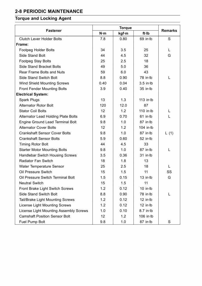
Torque and Locking Agent
The following tables list the tightening torquefor the major fasteners requiring use of a non-permanent locking agent or liquid gasket.
Letters used in the “Remarks” column mean:AL: Tighten the two clamp bolts alternately
two times to ensure even tighteningtorque.
L: Apply a non-permanent locking agent tothe threads.
G: Apply grease to the threads.MO: Apply molybdenum disulfide grease oil
solution.O: Apply oil to the threads and seating sur-face.
S: Tighten the fasteners following the speci-fied sequence.
SS: Apply silicone sealant.Si: Apply silicone grease (ex. PBC grease).R: Replacement parts
The table below, relating tightening torque tothread diameter, lists the basic torque for thebolts and nuts. Use this table for only the boltsand nuts which do not require a specific torquevalue. All of the values are for use with drysolvent-cleaned threads.
Basic Torque for General FastenersThreads Torque
dia.(mm)
N·m kgf·m ft·lb
5 3.4 ∼ 4.9 0.35 ∼ 0.50 30 ∼ 43 in·lb6 5.9 ∼ 7.8 0.60 ∼ 0.80 52 ∼ 69 in·lb8 14 ∼ 19 1.4 ∼ 1.9 10.0 ∼ 13.510 25 ∼ 34 2.6 ∼ 3.5 19.0 ∼ 2512 44 ∼ 61 4.5 ∼ 6.2 33 ∼ 4514 73 ∼ 98 7.4 ∼ 10.0 54 ∼ 7216 115 ∼ 155 11.5 ∼ 16.0 83 ∼ 11518 165 ∼ 225 17.0 ∼ 23.0 125 ∼ 16520 225 ∼ 325 23 ∼ 33 165 ∼ 240
TorqueFastener
N·m kgf·m ft·lbRemarks
Fuel System:
Air Cleaner Housing Mounting Bolt 6.9 0.70 61 in·lb
Air Inlet Duct Mounting Bolts 6.9 0.70 61 in·lb
Air Cleaner Housing Holder Clamp Bolts 2.5 0.25 22 in·lb
Intake Air Pressure Sensor Screw 4.9 0.50 43 in·lb
Atmospheric Pressure Sensor Screw 4.9 0.50 43 in·lb
Fuel Delivery Pipe Mounting Screws 3.4 0.35 30 in·lb
Throttle Body Assembly Holder Clamp Bolts 3.0 0.31 27 in·lb
Throttle Body Assembly Holder Bolts 12 1.2 106 in·lb L
Camshaft Position Sensor 12 1.2 106 in·lb
Water Temperature Sensor 25 2.5 18 SS
Vehicle-Down Sensor 2.0 0.20 17 in·lb
Speed Sensor Mounting Bolt 3.9 0.40 35 in·lb L
Crankshaft Sensor Mounting Bolts 5.9 0.60 52 in·lb
Fuel Pump Bolts 9.8 1.0 87 in·lb
Cooling System:
Water Hose Clamp Screws 2.0 0.20 17 in·lb
Coolant Drain Plug (Water Pump) 8.8 0.90 78 in·lb
Coolant Drain Plug (Cylinder) 8.8 0.90 78 in·lb
Radiator Fan Switch 18 1.8 13
Water Temperature Sensor 25 2.5 18 SS
Water Pump Impeller Bolt 9.8 1.0 87 in·lb
Water Pump Cover Bolts 12 1.2 104 in·lb L
Thermostat Housing Cover Bolts 5.9 0.60 52 in·lb

PERIODIC MAINTENANCE 2-5
Torque and Locking Agent
TorqueFastener
N·m kgf·m ft·lbRemarks
Coolant By-pass Fitting 8.8 0.90 78 in·lb L
Water Hose Fitting Bolts 12 1.2 106 in·lb
Radiator Mounting Bolts 6.9 0.70 61 in·lb
Radiator Bracket Mounting Bolts 6.9 0.70 61 in·lb
Coolant Reserve Tank Mounting Screws 6.9 0.70 61 in·lb
Oil Cooler Bolt 78 8.0 58
Water Passage Plugs 20 2.0 14
Engine Top End:
Spark Plugs 13 1.3 113 in·lb
Air Suction Valve Cover Bolts 12 1.2 104 in·lb L
Cylinder Head Cover Bolts 9.8 1.0 87 in·lb
Camshaft Chain Tensioner Mounting Bolts 9.8 1.0 87 in·lb
Camshaft Cap Bolts 12 1.2 104 in·lb
Cylinder Head Bolts: φ9 40 4.1 30S, O
(Washer)
φ6 12 1.2 104 in·lb S
Cylinder Head Jacket Plug (Left) 20 2.0 14.5 L
Cylinder Head Jacket Plug (Upper) 20 2.0 14.5 L
Front Camshaft Chain Guide Bolt (Upper) 25 2.5 18
Throttle Valve Holder Bolts 12 1.2 104 in·lb
Exhaust Pipe Clamp Bolts 17 1.7 12
Coolant By-pass Fitting 8.8 0.90 78 in·lb L
Water Temperature Sensor 25 2.5 18 SS
Camshaft Position Sensor Bolt 12 1.2 104 in·lb
Camshaft Sprocket Bolts 15 1.5 11 L
Front Camshaft Chain Guide Bolt (Lower) 12 1.2 104 in·lb
Rear Camshaft Chain Guide Bolt 25 2.5 18
Camshaft Chain Tensioner Cap Bolt 29 3.0 21
Water Jacket Drain Bolt 8.8 0.90 78 in·lb
Exhaust Pipe Manifold Nut 17 1.7 12
Muffler Body Bolt 30 3.0 22
Clutch:
Clutch Cover Bolts 12 1.2 104 in·lb L(2, Front)
Clutch Spring Bolts 8.8 0.90 78 in·lb
Clutch Hub Nut 130 13.5 98 R
Clutch Lever Holder Bolts 7.8 0.80 69 in·lb S
Clutch Sub Hub Bolts 25 2.5 18 L
Engine Lubrication System:
Oil Filler Plug 1.5 0.15 13 in·lb
Engine Drain Plug 29 3.0 22
Oil Filter (Cartridge type) 31 3.2 23 R, O
Oil Cooler Bolt 78 8.0 58 R
Oil Pan Bolts 9.8 1.0 87 in·lb

2-6 PERIODIC MAINTENANCE
Torque and Locking Agent
TorqueFastener
N·m kgf·m ft·lbRemarks
Oil Pipe Holder Bolts 12 1.2 104 in·lb
Oil Pressure Relief Valve 15 1.5 11 L
Oil Pressure Switch 15 1.5 11 SS
Oil Pressure Switch Terminal Bolt 1.5 0.15 13 in·lb G
Impeller Bolt 9.8 1.0 87 in·lb
Oil Passage Plug 15 1.5 11
Oil Jet Nozzle Bolts 6.9 0.70 61 in·lb
Cooling Hose Clamp 2.0 0.20 17 in·lb
Oil Filter Clamp Bolt 5.9 0.60 52 in·lb
Engine Removal/Installation:
Engine Mounting Bolts and Nuts 44 4.5 33 S
Engine Mounting Locknuts 49 5.0 36
Engine Mounting Adjusting Bolts 20 2.0 14 S
Crankshaft/Transmission:
Breather Plate Bolts 9.8 1.0 87 in·lb L
Oil Passage Plug (Left) 20 2.0 14.5 L
Oil Passage Plug (Right) 15 1.5 11
Connecting Rod Big End Nuts in the text ← ←Harness Clamp Bolt 8.8 0.90 78 in·lb
Timing Rotor Bolt 44 4.5 33
Oil Pressure Switch 15 1.5 11 SS
Gear Positioning Lever Bolt 9.8 1.0 87 in·lb
Shift Shaft Return Spring Pin (Bolt) 28 2.9 21 L
Neutral Switch 15 1.5 11
Shift Drum Bearing Holder Bolt 12 1.2 104 in·lb
Shift Drum Bearing Holder Screw 4.9 0.50 43 in·lb L
Shift Drum Cam Holder Bolt 12 1.2 104 in·lb L
Oil Pipe Holder Bolts 12 1.23 104 in·lb
Crankshaft Sensor Cover Bolts 9.8 1.0 87 in·lb L (1)
Oil Jet Nozzle Bolts 6.9 0.70 61 in·lb L
Starter Motor Clutch Bolt 33 3.4 24 L
Upper Crankcase Bolts (7mm) 20 2.0 14.5 S
Upper Crankcase Bolts (6mm) 12 1.2 104 in·lb S
Lower Crankcase Bolts (7mm) (Front) 27 2.8 20 S
Lower Crankcase Bolts (7mm) (Rear) 24 2.4 18 S
Lower Crankcase Bolts(6mm) 12 1.2 104 in·lb S
Wheels/Tires:
Front Axle Clamp Bolts 20 2.0 14.5 AL
Front Axle Nut 127 13.0 94
Rear Axle Nut 127 13.0 94
Final Drive:
Engine Sprocket Nut 125 13.0 92 MO
Engine Sprocket Cover Bolts 6.9 0.70 61 in·lb

PERIODIC MAINTENANCE 2-7
Torque and Locking Agent
TorqueFastener
N·m kgf·m ft·lbRemarks
Speed Sensor Mounting Bolt 3.9 0.40 35 in·lb L
Rear Sprocket Nuts 59 6.0 43
Rear Sprocket Studs – – – L
Brakes:
Bleed Valves 7.8 0.80 69 in·lb
Brake Hose Banjo Bolts 25 2.5 18
Brake Lever Pivot Bolt 1.0 0.10 9 in·lb Si
Brake Lever Pivot Bolt Locknut 6.0 0.61 53 in·lb
Front Brake Reservoir Cap Stopper Screws 1.2 0.12 10 in·lb
Front Brake Light Switch Screws 1.2 0.12 10 in·lb
Front Master Cylinder Clamp Bolts 8.8 0.90 78 in·lb S
Front Caliper Mounting Bolts 34 3.5 25
Caliper Assembly Bolts (Front) 22 2.2 16
Front Brake Disc Mounting Bolts 27 2.8 20 L
Rear Brake Disc Mounting Bolts 27 2.8 20 L
Rear Caliper Mounting Bolts 25 2.5 18
Rear Master Cylinder Mounting Bolts 25 2.5 18
Rear Master Cylinder Push Rod Locknut 18 1.8 13
Front Brake Pad Pins 15 1.5 11
Suspension:
Front Fork Clamp Bolts (Upper) 20 2.0 14.5
Front Fork Clamp Bolts (Lower) 20 2.0 14.5 AL
Front Fork Top Plugs 23 2.3 17
Piston Rod Nut 15 1.5 11
Front Fork Bottom Allen Bolts 40 4.0 30 L
Front Axle Clamp Bolts 20 2.0 14.5 AL
Rear Shock Absorber Nuts (Upper andLower)
34 3.5 25
Rear Shock Absorber Upper Bracket Nut 59 6.0 43
Swingarm Pivot Shaft Nut 108 11 81
Uni-Trak
Rocker Arm Nut 34 3.5 25
Tie-Rod Nuts 59 6.0 43
Swingarm Pivot Shaft ZX636 20 2.0 14
ZX600 25 2.5 18
Swingarm Pivot Shaft Lock Nut 98 10 72
Steering:
Steering Stem Head Nut 78 8.0 58
Steering Stem Nut 20 2.0 14.5
Handlebar Bolts 25 2.5 18
Handlebar Holder Position Bolts 9.8 1.0 87 in·lb L
Handlebar Weight Screws – – – L
Handlebar Switch Housing Screws 3.5 0.36 31 in·lb
2-8 PERIODIC MAINTENANCE
Torque and Locking Agent
TorqueFastener
N·m kgf·m ft·lbRemarks
Clutch Lever Holder Bolts 7.8 0.80 69 in·lb S
Frame:
Footpeg Holder Bolts 34 3.5 25 L
Side Stand Bolt 44 4.5 32 G
Footpeg Stay Bolts 25 2.5 18
Side Stand Bracket Bolts 49 5.0 36
Rear Frame Bolts and Nuts 59 6.0 43
Side Stand Switch Bolt 8.8 0.90 78 in·lb L
Wind Shield Mounting Screws 0.40 0.04 3.5 in·lb
Front Fender Mounting Bolts 3.9 0.40 35 in·lb
Electrical System:
Spark Plugs 13 1.3 113 in·lb
Alternator Rotor Bolt 120 12.0 87
Stator Coil Bolts 12 1.2 110 in·lb L
Alternator Lead Holding Plate Bolts 6.9 0.70 61 in·lb L
Engine Ground Lead Terminal Bolt 9.8 1.0 87 in·lb
Alternator Cover Bolts 12 1.2 104 in·lb
Crankshaft Sensor Cover Bolts 9.8 1.0 87 in·lb L (1)
Crankshaft Sensor Bolts 5.9 0.60 52 in·lb
Timing Rotor Bolt 44 4.5 33
Starter Motor Mounting Bolts 9.8 1.0 87 in·lb L
Handlebar Switch Housing Screws 3.5 0.36 31 in·lb
Radiator Fan Switch 18 1.8 13
Water Temperature Sensor 25 2.5 18 L
Oil Pressure Switch 15 1.5 11 SS
Oil Pressure Switch Terminal Bolt 1.5 0.15 13 in·lb G
Neutral Switch 15 1.5 11
Front Brake Light Switch Screws 1.2 0.12 10 in·lb
Side Stand Switch Bolt 8.8 0.90 78 in·lb L
Tail/Brake Light Mounting Screws 1.2 0.12 12 in·lb
License Light Mounting Screws 1.2 0.12 12 in·lb
License Light Mounting Assembly Screws 1.0 0.10 8.7 in·lb
Camshaft Position Sensor Bolt 12 1.2 106 in·lb
Fuel Pump Bolt 9.8 1.0 87 in·lb S

PERIODIC MAINTENANCE 2-9
Specifications
Item Standard Service Limit
Fuel System:
Throttle grip free play 2 ∼ 3 mm (0.08 ∼ 0.12 in.) – – –
Idle speed 1 300 ± 50 r/min (rpm) – – –
Throttle body vacuum:
ZX636B 24 ± 1.3 kPa (180 ± 10 mmHg) – – –
ZX600K 22 ± 1.3 kPa (165 ± 10 mmHg) – – –
at Idle Speed
Air cleaner element Viscous paper element – – –
Cooling System:
Coolant:
Type (recommended) Permanent type antifreeze – – –
Color Green – – –
Mixed ratio Soft water 50%, Coolant 50% – – –
Freezing point –35°C (–31°F) – – –
Total amount 2.4 L (2.5 US qt.) – – –
Engine Top End:
Valve clearance:
Inlet 0.11 ∼ 0.19 mm (0.004 ∼ 0.008 in.) – – –
Exhaust 0.22 ∼ 0.31 mm (0.009 ∼ 0.012 in.) – – –
Clutch:
Clutch lever free play 2 ∼ 3 mm (0.08 ∼ 0.12 in.) – – –
Engine Lubrication System:
Engine oil:
Type API SE, SF or SG – – –
API SH or SJ with JASO MA
Viscosity SAE 10W-40 – – –
Capacity3.4 L (3.6 US qt) (when filter is notremoved)
– – –
3.6 L (3.8 US qt) (when filter is removed) – – –
4.0 L (4.2 US qt) (when engine iscompletely dry)
– – –
Level Between upper and lower level lines – – –
(Wait 2 ∼ 3 minutes after idling orrunning)
Tires:
Tread depth:
Front BRIDGESTONE 3.8 mm (0.15 in.)
MICHELIN 3.8 mm (0.15 in.)
1 mm (0.04 in.)(DE, AT, CH)1.6 mm (0.06 in.)
Rear BRIDGESTONE 5.8 mm (0.23 in.)
MICHELIN 5.6 mm (0.22 in.)
Up to 130 km/h (80mph): 2 mm (0.08in.)Over 130 km/h (80mph): 3 mm (0.12in.)

2-10 PERIODIC MAINTENANCE
Specifications
Item Standard Service Limit
Air pressure: (when cold)
Front Up to 180 kg (397 lb) load: – – –
250 kPa (2.5 kgf/cm², 36 psi)
Rear Up to 180 kg (397 lb) load:
290 kPa (2.9 kgf/cm², 42 psi)– – –
Final Drive:
Drive chain slack 25 ∼ 30 mm (1.0 ∼ 1.2 in.) – – –
Drive chain wear (20-link length) 317.5 ∼ 318.2 mm (12.50 ∼ 12.53 in.) 323 mm (12.7 in.)
Brakes:
Brake fluid:
Grade DOT4 – – –
Brake pad lining thickness:
Front 4.0 mm (0.16 in.) 1 mm (0.04 in.)
Rear 5 mm (0.20 in.) 1 mm (0.04 in.)
Brake light timing:
Front Pulled ON – – –
RearOn after about 10 mm (0.39 in.) of pedaltravel
– – –
Electrical System:
Spark plug gap 0.7 ∼ 0.8 mm (0.028 ∼ 0.031 in.) – – –
AT: AustriaCH: SwitzerlandDE: GermanyUS: United States
PERIODIC MAINTENANCE 2-11
Special Tools
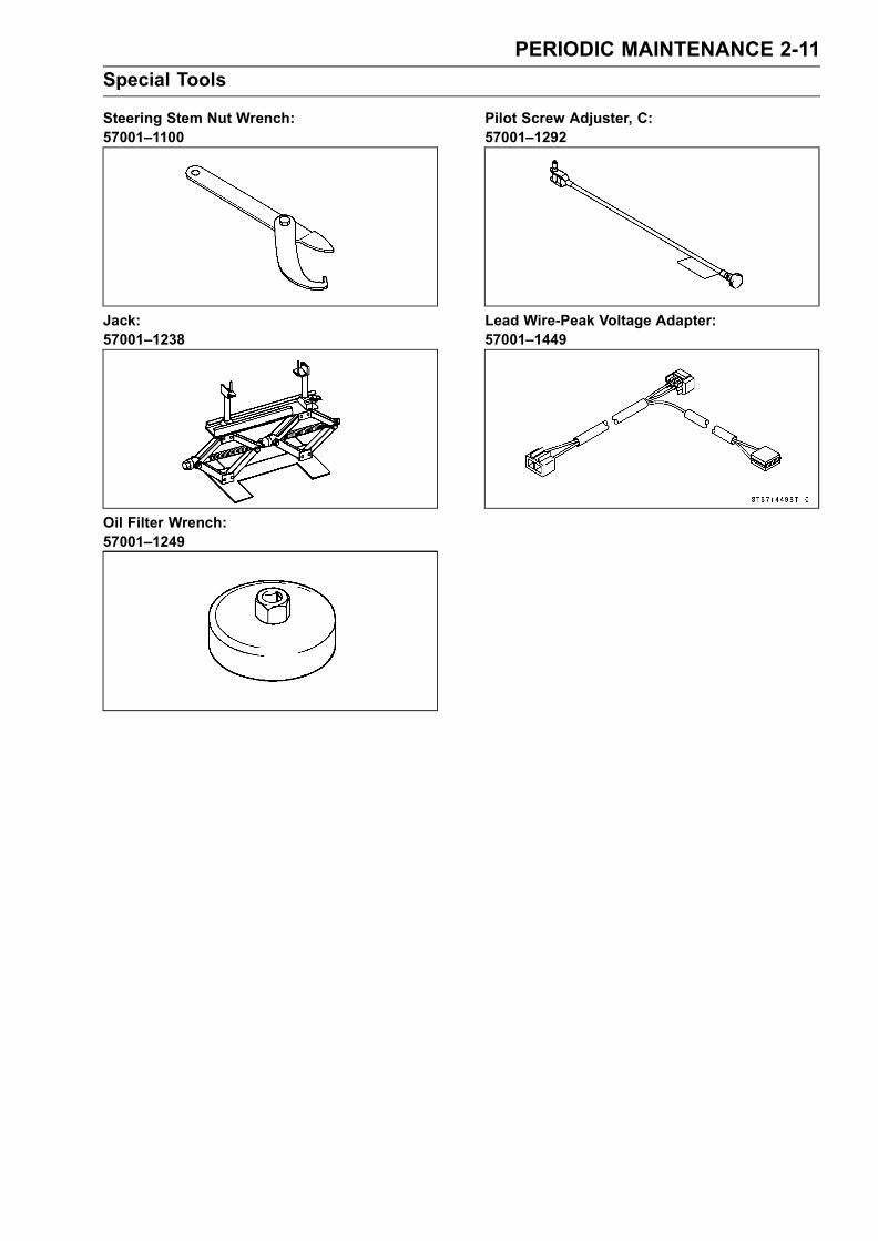
Steering Stem Nut Wrench:57001–1100
Jack:57001–1238
Oil Filter Wrench:57001–1249
Pilot Screw Adjuster, C:57001–1292
Lead Wire-Peak Voltage Adapter:57001–1449

2-12 PERIODIC MAINTENANCE
Maintenance Procedure
Fuel System (DFI)Fuel Hose and Connection InspectionThe fuel hose [A] is designed to be used throughout themotorcycle’s life without any maintenance. However, ifthe motorcycle is not properly handled, the high pressureinside the fuel line can cause fuel to leak or the hose toburst. Remove the fuel tank (see Fuel System (DFI) chap-ter) and check the fuel hose.Replace the fuel hose if any fraying, cracks [B] or bulges[C] are noticed.
•Check that the hose joints are securely connected.•When installing the fuel hose, avoid sharp bending, kink-ing, flattening or twisting.Replace the hose if it has been sharply bent or kinked.
Throttle Control System InspectionFree Play Inspection
•Check the throttle grip free play [A].If the free play is incorrect, adjust the throttle cables.
Throttle Grip Free PlayStandard: 2 ∼ 3 mm (0.08 ∼ 0.12 in)
•Check that the throttle grip [B] moves smoothly from fullopen to close, and the throttle closes quickly and com-pletely by the return spring in all steering positions.If the throttle grip does not return properly, check the throt-tle cables routing, grip free play, and cable damage. Thenlubricate the throttle cable.
•Run the engine at the idle speed, and turn the handlebarall the way to the right and left to ensure that the idle speeddoes not change.If the idle speed increases, check the throttle cable freeplay and the cable routing.
Free Play Adjustment
•Loosen the locknuts [A] [B].• Screw both throttle cable adjusters [C] [D] to give thethrottle grip plenty of play.
• Turn out the decelerator cable adjuster [C] until there isno play when the throttle grip is completely closed.
• Tighten the locknut [A].Turn the accelerator cable adjuster [D] until 2 ∼ 3 mm(0.08 ∼ 0.12 in.) of throttle grip play is obtained.• Tighten the locknut [B]If the free paly cannot be adjusted with the adjusters, re-place the cable.

PERIODIC MAINTENANCE 2-13
Maintenance Procedure
Throttle Bore Cleaning
•Check the throttle bore for cleanliness as follows:Remove:Throttle Body (see Fuel System (DFI) chapter)
Check the main throttle valves and throttle bores [A] forcarbon deposits by opening the main throttle valves.If any carbon accumulates, wipe the carbon off the throt-tle bores around the throttle bores and the throttle valves,using a cotton pad penetrated with a high-flash point sol-vent. Be careful not to remove molybdenum disulfide coat(black) [B] from the throttle valves and the bores.
CAUTION
Donot rub these surfaces hard and do not use a car-buretor cleaning solution, which damage molybde-num disulfide coat; instead, use a high-flash pointcleaning solution and wipe slowly.
Idle Speed Inspection
•Start the engine and warm it up thoroughly.
•With the engine idling, turn the handlebar to both sides[A].If handlebar movement changes the idle speed, thethrottle cables may be improperly adjusted or incorrectlyrouted, or damaged. Be sure to correct any of theseconditions before riding (see Cable Routing Section inAppendix chapter).
WARNINGOperation with improperly adjusted, incorrectlyrouted, or damaged cables could result in an un-safe riding condition.
•Check the idle speed.If the idle speed is out of specified range, adjust it.
Idle SpeedStandard: 1 300 ± 50 r/min (rpm)
Idle Speed Adjustment
•Start the engine and warm it up thoroughly.
• Turn the adjusting screw [A] until the idle speed is correct.Open and close the throttle a few times to make sure thatthe idle speed is within the specified range. Readjust ifnecessary.

2-14 PERIODIC MAINTENANCE
Maintenance Procedure
Engine Vacuum Synchronization Inspection
NOTEThese procedures are explained on the assumption thatthe inlet and exhaust systems of the engine are in goodcondition.
•Situate the motorcycle so that it is vertical.• Remove:Air Cleaner Housing (see Fuel System (DFI) chapter)
• Pull off the vacuum hoses [A] and the rubber cap [B] fromthe right fittings of each throttle body.
• For California model, pull off the vacuum hose [C].CAUTION
Do not remove the inlet air pressure sensor hoses[D] on the left fitting of each throttle body.
•Connect a commercially available vacuum gauge andhoses [A] to the fittings on the throttle body.
•Connect a highly accurate tachometer to one of the stickcoil primary leads using the adapter [A].
Special Tool - Lead Wire-Peak Voltage Adapter:57001-1449
•Position the fuel tank so that the throttle bodies can bereached.Connect a commercially available fuel hose [A] and a fuelpump lead connector [B].Secure the fuel hose with clamps.
PERIODIC MAINTENANCE 2-15
Maintenance Procedure
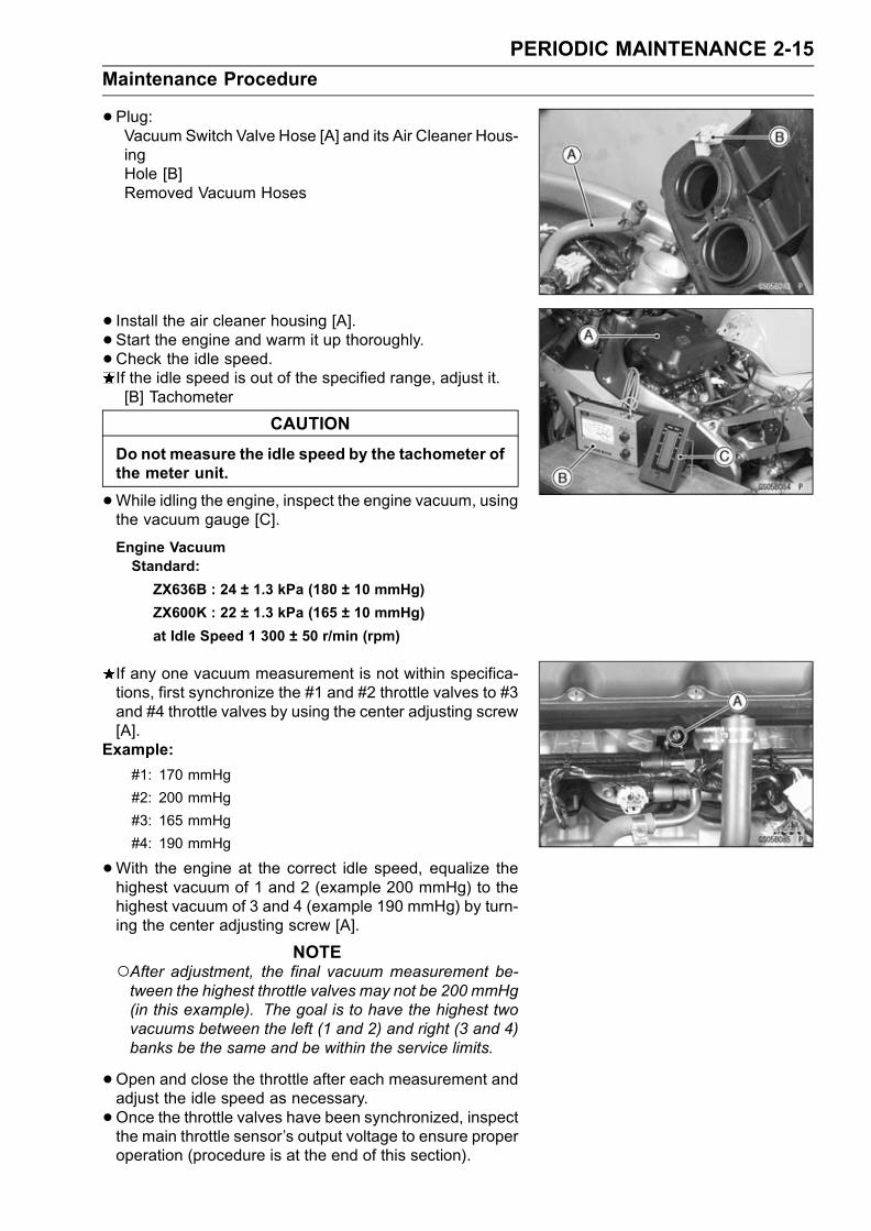
•Plug:Vacuum Switch Valve Hose [A] and its Air Cleaner Hous-ingHole [B]Removed Vacuum Hoses
• Install the air cleaner housing [A].• Start the engine and warm it up thoroughly.
•Check the idle speed.If the idle speed is out of the specified range, adjust it.[B] Tachometer
CAUTION
Do not measure the idle speed by the tachometer ofthe meter unit.
•While idling the engine, inspect the engine vacuum, usingthe vacuum gauge [C].
Engine VacuumStandard:
ZX636B : 24 ± 1.3 kPa (180 ± 10 mmHg)
ZX600K : 22 ± 1.3 kPa (165 ± 10 mmHg)
at Idle Speed 1 300 ± 50 r/min (rpm)
If any one vacuum measurement is not within specifica-tions, first synchronize the #1 and #2 throttle valves to #3and #4 throttle valves by using the center adjusting screw[A].
Example:
#1: 170 mmHg
#2: 200 mmHg
#3: 165 mmHg
#4: 190 mmHg
•With the engine at the correct idle speed, equalize thehighest vacuum of 1 and 2 (example 200 mmHg) to thehighest vacuum of 3 and 4 (example 190 mmHg) by turn-ing the center adjusting screw [A].
NOTEAfter adjustment, the final vacuum measurement be-tween the highest throttle valves may not be 200 mmHg(in this example). The goal is to have the highest twovacuums between the left (1 and 2) and right (3 and 4)banks be the same and be within the service limits.
•Open and close the throttle after each measurement andadjust the idle speed as necessary.
•Once the throttle valves have been synchronized, inspectthe main throttle sensor’s output voltage to ensure properoperation (procedure is at the end of this section).
2-16 PERIODIC MAINTENANCE
Maintenance Procedure
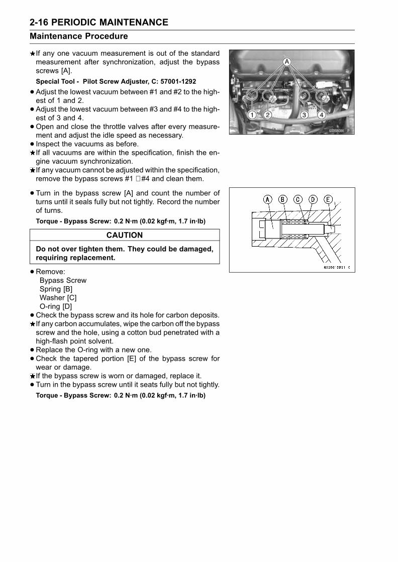
If any one vacuum measurement is out of the standardmeasurement after synchronization, adjust the bypassscrews [A].
Special Tool - Pilot Screw Adjuster, C: 57001-1292
•Adjust the lowest vacuum between #1 and #2 to the high-est of 1 and 2.
• Adjust the lowest vacuum between #3 and #4 to the high-est of 3 and 4.
•Open and close the throttle valves after every measure-ment and adjust the idle speed as necessary.
• Inspect the vacuums as before.If all vacuums are within the specification, finish the en-gine vacuum synchronization.If any vacuum cannot be adjusted within the specification,remove the bypass screws #1 ∼ #4 and clean them.
• Turn in the bypass screw [A] and count the number ofturns until it seals fully but not tightly. Record the numberof turns.
Torque - Bypass Screw: 0.2 N·m (0.02 kgf·m, 1.7 in·lb)
CAUTION
Do not over tighten them. They could be damaged,requiring replacement.
•Remove:Bypass ScrewSpring [B]Washer [C]O-ring [D]
•Check the bypass screw and its hole for carbon deposits.If any carbon accumulates, wipe the carbon off the bypassscrew and the hole, using a cotton bud penetrated with ahigh-flash point solvent.
•Replace the O-ring with a new one.•Check the tapered portion [E] of the bypass screw forwear or damage.If the bypass screw is worn or damaged, replace it.
• Turn in the bypass screw until it seats fully but not tightly.Torque - Bypass Screw: 0.2 N·m (0.02 kgf·m, 1.7 in·lb)

PERIODIC MAINTENANCE 2-17
Maintenance Procedure
•Back out the same number of turns counted when firstturned in. This is to set the screw to its original position.
NOTEA throttle body has different “turns out” of the bypassscrew for each individual unit. When setting the bypassscrew, use the “turns out” determined during disassem-bly. Use the specifications in this manual only if the orig-inal number is unknown.
•Repeat the same procedure for other bypass screws.•Repeat the synchronization.If the vacuums are correct, check the output voltage ofthe main throttle sensor (see Output Voltage Inspection ofMain Throttle Sensor in the Fuel System (DFI) chapter).
Main Throttle Sensor Output VoltageConnections to ECU
Meter (+) → Y/W lead (terminal 2)
Meter (–)→ BR/BK lead (terminal 14)
Standard:
1.02 ∼ 1.06 V DC (at idle throttle opening)
If the output voltage is out of the range, check the throttleinput voltage (see Input Voltage Inspection of Main Throt-tle Sensor in the Fuel System (DFI) chapter).
• Remove the vacuum gauge hoses and install the vacuumhoses and rubber caps on the original position as shown.Vacuum Switch Valve Vacuum Hoses [A]Rubber Cap [B]Vacuum Hose [C] (California model) or Rubber Cap (ex-cept California model)
Air Cleaner Element Replacement
WARNINGIf dirt or dust is allowed to pass through into thethrottle assy, the throttle may become stuck, possi-bly causing an accident.
CAUTION
If dirt gets through into the engine, excessive en-gine wear and possibly engine damage will occur.
2-18 PERIODIC MAINTENANCE
Maintenance Procedure
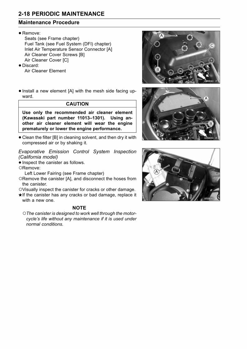
•Remove:Seats (see Frame chapter)Fuel Tank (see Fuel System (DFI) chapter)Inlet Air Temperature Sensor Connector [A]Air Cleaner Cover Screws [B]Air Cleaner Cover [C]
•Discard:Air Cleaner Element
• Install a new element [A] with the mesh side facing up-ward.
CAUTION
Use only the recommended air cleaner element(Kawasaki part number 11013–1301). Using an-other air cleaner element will wear the engineprematurely or lower the engine performance.
•Clean the filter [B] in cleaning solvent, and then dry it withcompressed air or by shaking it.
Evaporative Emission Control System Inspection(California model)
• Inspect the canister as follows.Remove:Left Lower Fairing (see Frame chapter)
Remove the canister [A], and disconnect the hoses fromthe canister.Visually inspect the canister for cracks or other damage.If the canister has any cracks or bad damage, replace itwith a new one.
NOTEThe canister is designed to work well through themotor-cycle’s life without any maintenance if it is used undernormal conditions.

PERIODIC MAINTENANCE 2-19
Maintenance Procedure
•Check the liquid/vapor separator as follows:Remove:Seats (see Frame chapter)
Disconnect the hoses from the separator, and remove theseparator [A] from the motorcycle right side.Visually inspect the separator for cracks and other dam-age.If the separator has any cracks or damage, replace it witha new one.To prevent the gasoline from flowing into or out of thecanister, hold the separator perpendicular to the ground.
•Check the hoses of the evaporative emission control sys-tem as follows:Check that the hoses are securely connected and clipsare in position.Replace any kinked, deteriorated or damaged hoses.Route the hoses according to Cable, Wire, and HoseRouting section in the Appendix chapter. Refer to the di-agram of the evaporative emission control system in theFuel System (DFI) chapter too.When installing the hoses, avoid sharp bending, kinking,flattening or twisting, and route the hoses with a minimumof bending so that the emission flow will not be obstructed.
Cooling SystemCooling Hose and Connection InspectionThe high pressure inside the radiator hose can causecoolant to leak [A] or the hose to burst if the line is notproperly maintained. Visually inspect the hoses for signsof deterioration. Squeeze the hoses. A hose should notbe hard and brittle, nor should it be soft or swollen.Replace the hose if any fraying, cracks [B] or bulges [C]are noticed.
•Check that the hoses are securely connected and clampsare tightened correctly.
Torque - Radiator HoseClampScrews: 2.5 N·m (0.25 kgf·m,22 in·lb)
Coolant Change
WARNINGTo avoid burns, do not remove the radiator cap ortry to change the coolant when the engine is stillhot. Wait until it cools down. Coolant on tires willmake them slippery and can cause an accidentand injury. Immediately wipe up or wash away anycoolant that spills on the frame, engine, or otherpainted parts.Since coolant is harmful to the human body, do notuse for drinking.

2-20 PERIODIC MAINTENANCE
Maintenance Procedure
•Remove:Right Inner Cover (see Frame chapter)Radiator Cap [A]
Remove the radiator cap in two steps. First turn the capcounterclockwise to the first stop. Then push and turn itfurther in the same direction and remove the cap.
•Remove:Left Lower Fairing (see Frame chapter)
• Place a containers under the drain plugs [A] and [B] at thebottom of the water pump cover and cylinder.
•Drain the coolant from the radiator and engine by remov-ing the drain plugs.
•Remove:Coolant Reserve Tank [A] (see Cooling System chapter)
•Remove the cap [B] and pour the coolant into a container.
• Install the reserve tank (see Cooling System chapter).• Tighten the drain plugs with the washers.Replace the drain plug gasket with a new one if it is dam-aged.
Torque - Coolant Drain Plug (Water Pump): 12 N·m (1.2kgf·m, 106 in·lb)
Coolant Drain Plug (Cylinder): 10 N·m (1.0 kgf·m,89 in·lb)
•Fill the radiator up to the radiator filler neck [A] withcoolant, and install the radiator cap.
NOTEPour in the coolant slowly so that it can expel the airfrom the engine and radiator.
•Fill the reserve tank up to the full level line with coolant,and install the cap.
CAUTION
Soft or distilled water must be used with the an-tifreeze (see below for antifreeze) in the cooling sys-tem.If hard water is used in the system, it causes scalesaccumulation in the water passages, and consider-ably reduces the efficiency of the cooling system.

PERIODIC MAINTENANCE 2-21
Maintenance Procedure
Water and Coolant Mixture Ratio (Recommended)Soft Water: 50 %
Coolant: 50 %
Freezing Point: – 35°C (– 31°F)
Total Amount: 2.4 L (2.5 US qt)
NOTEChoose a suitable mixture ratio by referring to thecoolant manufacturer’s directions.
•Bleed the air from the cooling system as follows.Start the engine with the radiator cap removed and run ituntil no more air bubbles [A] can be seen in the coolant.Tap the radiator hoses to force any air bubbles caughtinside.Stop the engine and add coolant up to the radiator fillerneck.
• Install the radiator cap.• Start the engine, warm it up thoroughly until the radiatorfan turns on and then stop the engine.
•Check the coolant level in the reserve tank after the en-gine cools down.If the coolant level is lower than the low level line, addcoolant to the full level line.
CAUTION
Do not add more coolant above the full level line.
Engine Top EndAir Suction Valve Check
•Remove the air suction valve (see Engine Top End chap-ter).
• Visually inspect the reeds [A] for cracks, folds, warps,heat damage, or other damage.If there is any doubt as to the condition of the reed, replacethe air suction valve as an assembly.
•Check the reed contact areas [B] of the valve holder forgrooves, scratches, any signs of separation from theholder, or heat damage.If there is any doubt as to the condition of the reed contactareas, replace the air suction valve as an assembly.
• If any carbon or other foreign particles have accumulatedbetween the reed and the reed contact area, wash thevalve assembly with a high flash-point solvent.
CAUTION
Do not scrape off the deposits with a scraper as thiscould damage the rubber, requiring replacement ofthe suction valve assembly.

2-22 PERIODIC MAINTENANCE
Maintenance Procedure
Valve Clearance CheckValve Clearance Inspection
NOTEValve clearance must be checked and adjusted whenthe engine is cold (at room temperature).
•Remove:Lower Fairings (see Frame chapter)Pickup Coil Cover
Cylinder Head Cover (see Engine Top End chapter)
• Position the crankshaft at 1,4 piston TDC.TDC Mark [A] for #1, 4 PistonsTiming Mark [B] (crankcase halves mating surface)
•Using a thickness gauge [A], measure the valve clearancebetween the cam and the valve lifter.
Valve ClearanceStandard: IN: 0.11∼ 0.19 mm (0.004 ∼ 0.008 in.)
EX: 0.22 ∼ 0.31 mm (0.009 ∼ 0.012 in.)
When positioning #4 piston TDC at the end of thecompression stroke:Inlet valve clearance of #2 and #4 cylindersExhaust valve clearance of #3 and #4 cylindersMeasuring Valve [A]
When positioning #1 piston TDC at the end of thecompression stroke:Inlet valve clearance of #1 and #3 cylindersExhaust valve clearance of #1 and #2 cylindersMeasuring Valve [A]
If the valve clearance is not within the specified range,first record the clearance, and then adjust it.
PERIODIC MAINTENANCE 2-23
Maintenance Procedure
Valve Clearance Adjustment
•To change the valve clearance, remove the camshaftchain tensioner, camshafts and valve lifters. Replace theshim with one of a different thickness.
NOTEMark and record the valve lifter and shim locations sothey can be reinstalled in their original positions.If there is no clearance, select a shim which is severalsizes smaller and then measure the clearance.
•To select a new shim which brings the valve clearancewithin the specified range, refer to the Valve ClearanceAdjustment Charts.
• Apply a thin coat of molybdenum disulfide grease to thevalve lifters.
• Install the camshafts. Be sure to time the camshafts prop-erly (see Engine Top End chapter).
• Remeasure any valve clearance that was adjusted.Readjust if necessary.
CAUTION
Do not put shim stock under the shim. This maycause the shim to pop out at high rpm, causing ex-tensive engine damage.Do not grind the shim. Thismay cause it to fracture,causing extensive engine damage.

2-24 PERIODIC MAINTENANCE
Maintenance Procedure
VALVE CLEARANCE ADJUSTMENT CHART INLET VALVE
1. Measure the clearance (when engine is cold).2. Check present shim size.3. Match clearance in vertical column with present shimsize in horizontal column.
4. Install the shim specified where the lines intersect. Thisshim will give the proper clearance.
Example: Present shim is 3.05 mm
Measured clearance is 0.35 mm
Replace 3.05 mm shim with 3.25 mm shim.
5. Remeasure the valve clearance and readjust if neces-sary.

PERIODIC MAINTENANCE 2-25
Maintenance Procedure
VALVE CLEARANCE ADJUSTMENT CHART EXHAUST VALVE
1. Measure the clearance (when engine is cold).2. Check present shim size.3. Match clearance in vertical column with present shimsize in horizontal column.
4. Install the shim specified where the lines intersect. Thisshim will give the proper clearance.
Example: Present shim is 3.10 mm.
Measured clearance is 0.40 mm.
Replace 3.10 mm shim with 3.2 mm shim.
5. Remeasure the valve clearance and readjust if neces-sary.
2-26 PERIODIC MAINTENANCE
Maintenance Procedure
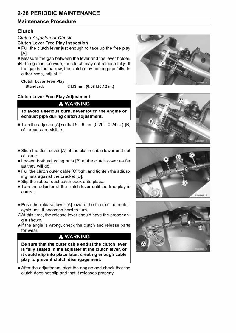
ClutchClutch Adjustment CheckClutch Lever Free Play Inspection
•Pull the clutch lever just enough to take up the free play[A].
•Measure the gap between the lever and the lever holder.If the gap is too wide, the clutch may not release fully. Ifthe gap is too narrow, the clutch may not engage fully. Ineither case, adjust it.
Clutch Lever Free PlayStandard: 2 ∼ 3 mm (0.08 ∼ 0.12 in.)
Clutch Lever Free Play Adjustment
WARNINGTo avoid a serious burn, never touch the engine orexhaust pipe during clutch adjustment.
•Turn the adjuster [A] so that 5 ∼ 6 mm (0.20 ∼ 0.24 in.) [B]of threads are visible.
• Slide the dust cover [A] at the clutch cable lower end outof place.
• Loosen both adjusting nuts [B] at the clutch cover as faras they will go.
• Pull the clutch outer cable [C] tight and tighten the adjust-ing nuts against the bracket [D].
• Slip the rubber dust cover back onto place.• Turn the adjuster at the clutch lever until the free play iscorrect.
• Push the release lever [A] toward the front of the motor-cycle until it becomes hard to turn.At this time, the release lever should have the proper an-gle shown.If the angle is wrong, check the clutch and release partsfor wear.
WARNINGBe sure that the outer cable end at the clutch leveris fully seated in the adjuster at the clutch lever, orit could slip into place later, creating enough cableplay to prevent clutch disengagement.
•After the adjustment, start the engine and check that theclutch does not slip and that it releases properly.

PERIODIC MAINTENANCE 2-27
Maintenance Procedure
Engine Lubrication SystemEngine Oil Change
•Situate the motorcycle so that it is vertical after warmingup the engine.
•Remove the engine drain plug [A] to drain the oil.The oil in the oil filter can be drained by removing the filter(see Oil Filter Replacement).Replace the drain plug gasket [B] with a new one if it isdamaged.
• Tighten the drain plug.Torque - Engine Drain Plug: 29 N·m (3.0 kgf·m, 22 ft·lb)
•Pour in the specified type and amount of oil.Recommended Engine OilType: API SE, SF or SG
API SH or SJ with JASO MA
Viscosity: SAE 10W40
Capacity:3.4 L (3.6 US qt) (when filter is notremoved)
3.6 L (3.8 US qt) (when filter isremoved)
4.0 L (4.2 US qt) (when engine iscompletely dry)
NOTEAlthough 10W-40 engine oil is the recommended oilfor most conditions, the oil viscosity may need to bechanged to accommodate atmospheric conditions inyour riding area.
Oil Filter Replacement
•Drain the engine oil (see Engine Oil Change).•Remove:Left Lower Fairing (see Frame chapter)Oil Filter Clamp
•Remove the oil filter [A] with the oil filter wrench [B].Special Tool - Oil Filter Wrench: 57001-1249
•Replace the filter with a new one.• Apply engine oil to the gasket [A] before installation.• Tighten the filter with the oil filter wrench.Torque - Oil Filter: 31 N·m (3.2 kgf·m, 23 ft·lb)
NOTEHand tightening of the oil filter can not be allowed sinceit does not reach to this tightening torque.

2-28 PERIODIC MAINTENANCE
Maintenance Procedure
• Install the oil filter clamp so that projection [B] fits the slot[A] of oil cooler.Be sure to place the rubber tube on the projection.• Tighten:Torque - Oil Filter Clamp Bolt [C]: 5.9 N·m (0.60 kgf·m, 52
in·lb)
•Pour in the specified type and amount of oil (see EngineOil Change).
Wheels/TiresTire Wear CheckTire InspectionAs the tire tread wears down, the tire becomes more sus-
ceptible to puncture and failure. An accepted estimate isthat 90 % of all tire failures occur during the last 10 % oftread life (90 % worn). So it is false economy and unsafe touse the tires until they are bald.
•Remove any imbedded stones or other foreign particlesfrom the tread.
• Visually inspect the tire for cracks and cuts, replacing thetire in case of damage. Swelling or high spots indicateinternal damage, requiring tire replacement.
•Measure the tread depth at the center of the tread with adepth gauge [A]. Since the tire may wear unevenly, takemeasurement at several places.If any measurement is less than the service limit, replacethe tire.
Tread DepthFront:
Standard: 3.8 mm (0.15 in.) (BRIDGESTONE),
3.8 mm (0.15 in.) (MICHELIN)
Service Limit: 1 mm (0.04 in.),
(DE, AT, CH) 1.6 mm (0.06 in.)
Rear:
Standard: 5.8 mm (0.23 in.) (BRIDGESTONE)
5.6 mm (0.22 in.) (MICHELIN)
Service Limit: 2 mm (0.08 in.)
(Up to 130 km/h, 80 mph)
3 mm (0.12 in.)
(Over 130 km/h, 80 mph)
WARNINGTo ensure safe handling and stability, use only therecommended standard tires for replacement, in-flated to the standard pressure.

PERIODIC MAINTENANCE 2-29
Maintenance Procedure
NOTEMost countries may have their own regulations a mini-mum tire tread depth: be sure to follow them.Check and balance the wheel when a tire is replacedwith a new one.
Air Pressure Inspection/Adjustment
•Measure the tire air pressure with an air pressure gauge[A] when the tires are cold (that is, when the motorcyclehas not been ridden more than a mile during the past 3hours).
• Install the air valve cap.Adjust the tire air pressure according to the specificationsif necessary.
Air Pressure (when cold)Front Up to 180 kg 250 kPa
(397 lb) (2.5 kgf/cm², 36 psi)
Rear Up to 180 kg 290 kPa
(397 lb) (2.9 kgf/cm², 42 psi)
Final DriveDrive Chain Wear CheckDrive Chain Slack Inspection
NOTECheck the slack with the motorcycle setting on its sidestand.Clean the chain if it is dirty, and lubricate it if it appearsdry.
•Check the wheel alignment (seeWheel Alignment Inspec-tion).
•Rotate the rear wheel to find the position where the chainis tightest.
•Measure the vertical movement (chain slack) [A] midwaybetween the sprockets.If the chain slack exceeds the standard, adjust it.
Chain SlackStandard: 25 ∼ 30 mm (1.0 ∼ 1.2 in.)
Drive Chain Slack Adjustment
•Remove the cotter pin [A], and loosen the axle nut [B].• Loosen the both chain adjuster locknuts [C].If the chain is too loose, turn out the left and right chainadjuster [D] evenly.If the chain is too tight, turn in the left and right chainadjusters evenly, and kick the wheel forward.
• Turn both chain adjusters evenly until the drive chain hasthe correct amount of slack. To keep the chain and wheelproperly aligned, the notch [E] on the left wheel alignmentindicator [F] should align with the same swingarm mark orposition [G] that the right indicator notch aligns with.

2-30 PERIODIC MAINTENANCE
Maintenance Procedure
WARNINGMisalignment of the wheel will result in abnormalwear and may result in an unsafe riding condition.
•Tighten both chain adjuster locknuts securely.• Tighten the axle nut.Torque - Rear Axle Nut: 127 N·m (13.0 kgf·m, 92 ft·lb)
•Turn the wheel, measure the chain slack again at the tight-est position, and readjust if necessary.
• Insert a new cotter pin [A].NOTE
When inserting the cotter pin, if the slots in the nut donot align with the cotter pin hole in hte axle, tighten thenut clockwise [B] up to next alignment.it should be within 30 degree.loosen once and tighten again when the slot goes pastthe nearest hole.
•Bend the cotter pin [A] over the nut [B].
Wheel Alignment Inspection/Adjustment
•Check that the notch [A] on the left alignment indicator [B]aligns with the same swingarm mark or position [C] thatthe right alignment indicator notch aligns with.If they do not, adjust the chain slack and align the wheelalignment (see Drive Chain Slack Adjustment ).
NOTEWheel alignment can be also checked using thestraightedge or string method.
WARNINGMisalignment of the wheel will result in abnormalwear, and may result in an unsafe riding condition.

PERIODIC MAINTENANCE 2-31
Maintenance Procedure
Drive Chain Wear Inspection
•Remove:Chain Cover
•Rotate the rear wheel to inspect the drive chain for dam-aged rollers, and loose pins and links.If there is any irregularity, replace the drive chain.Lubricate the drive chain if it appears dry.
• Stretch the chain taut by hanging a 98 N (10 kg, 20 lb)weight [A] on the chain.
•Measure the length of 20 links [B] on the straight part [C] ofthe chain from the pin center of the 1st pin to the pin centerof the 21st pin. Since the chain may wear unevenly, takemeasurements at several places.If any measurements exceed the service limit, replace thechain. Also, replace the front and rear sprockets when thedrive chain is replaced.
Drive Chain 20-link LengthStandard: 317.5 ∼ 318.2 mm (12.50 ∼ 12.53 in.)Service Limit: 323 mm (12.7 in.)
WARNINGIf the drive chain wear exceeds the service limit, re-place the chain or an unsafe riding condition mayresult. A chain that breaks or jumps off the sprock-ets could snag on the engine sprocket or lock therear wheel, severely damaging the motorcycle andcausing it to go out of control.For safety, use only the standard chain. It is an end-less type and should not be cut for installation.
Standard ChainMake: ENUMA
Type: EK520MVXL
Link: 108 Links

2-32 PERIODIC MAINTENANCE
Maintenance Procedure
Drive Chain Lubrication
• If a special lubricant is not available, a heavy oil such asSAE 90 is preferred to a lighter oil because it will stay onthe chain longer and provide better lubrication.
• If the chain appears especially dirty, clean it before lubri-cation.
CAUTION
The O-rings between the side plates seal in thelubricant between the pin and the bushing. Toavoid damaging the O-rings and resultant loss oflubricant, observe the following rules.Use only kerosene or diesel oil for cleaning of theO-ring of the drive chain.Any other cleaning solution such as gasolineor trichloroethylene will cause deterioration andswelling of the O-ring.Immediately blow the chain dry with compressedair after cleaning.Complete cleaning and drying the chain within 10minutes.
•Apply oil to the sides of the rollers so that oil will penetrateto the rollers and bushings. Apply the oil to the O-rings sothat the O-rings will be coated with oil.
•Wipe off any excess oil.Oil Applied Areas [A]O-ring [B]
BrakesBrake Pad Wear Check
•Remove the brake pads (see Brakes chapter).• Check the lining thickness [A] of the pads in each caliper.If the lining thickness of either pad is less than the servicelimit [B], replace both pads in the caliper as a set.
Pad Lining ThicknessStandard: Front 4 mm (0.16 in)
Rear 5 mm (0.20 in.)
Service Limit: 1 mm (0.04 in.)
Brake Light Switch CheckBrake Light Timing Inspection
•Turn on the ignition switch.•Check the operation of the rear brake light switch by de-pressing the brake pedal.If it does not as specified, adjust the brake light timing.
Brake Light Timing
Standard:On after about 10 mm (0.4 in.) ofpedal travel [A]
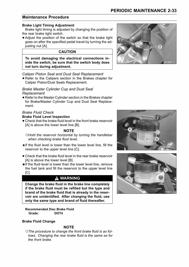
PERIODIC MAINTENANCE 2-33
Maintenance Procedure
Brake Light Timing AdjustmentBrake light timing is adjusted by changing the position of
the rear brake light switch.
• Adjust the position of the switch so that the brake lightgoes on after the specified pedal travel by turning the ad-justing nut [A].
CAUTION
To avoid damaging the electrical connections in-side the switch, be sure that the switch body doesnot turn during adjustment.
Caliper Piston Seal and Dust Seal Replacement
•Refer to the Calipers section in the Brakes chapter forCaliper Piston/Dust Seals Replacement.
Brake Master Cylinder Cup and Dust SealReplacement
•Refer to the Master Cylinder section in the Brakes chapterfor Brake/Master Cylinder Cup and Dust Seal Replace-ment.
Brake Fluid CheckBrake Fluid Level Inspection
•Check that the brake fluid level in the front brake reservoir[A] is above the lower level line [B].
NOTEHold the reservoir horizontal by turning the handlebarwhen checking brake fluid level.
If the fluid level is lower than the lower level line, fill thereservoir to the upper level line [C].
•Check that the brake fluid level in the rear brake reservoir[A] is above the lower level [B].If the fluid level is lower than the lower level line, removethe fuel tank and fill the reservoir to the upper level line[C].
WARNINGChange the brake fluid in the brake line completelyif the brake fluid must be refilled but the type andbrand of the brake fluid that is already in the reser-voir are unidentified. After changing the fluid, useonly the same type and brand of fluid thereafter.
Recommended Disc Brake FluidGrade: DOT4
Brake Fluid Change
NOTEThe procedure to change the front brake fluid is as fol-lows. Changing the rear brake fluid is the same as forthe front brake.
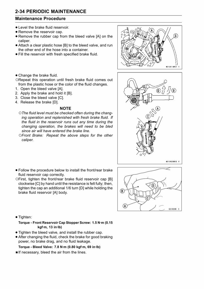
2-34 PERIODIC MAINTENANCE
Maintenance Procedure
•Level the brake fluid reservoir.• Remove the reservoir cap.•Remove the rubber cap from the bleed valve [A] on thecaliper.
• Attach a clear plastic hose [B] to the bleed valve, and runthe other end of the hose into a container.
• Fill the reservoir with fresh specified brake fluid.
•Change the brake fluid.Repeat this operation until fresh brake fluid comes outfrom the plastic hose or the color of the fluid changes.
1. Open the bleed valve [A].2. Apply the brake and hold it [B].3. Close the bleed valve [C].4. Release the brake [D].
NOTEThe fluid level must be checked often during the chang-ing operation and replenished with fresh brake fluid. Ifthe fluid in the reservoir runs out any time during thechanging operation, the brakes will need to be bledsince air will have entered the brake line.Front Brake: Repeat the above steps for the othercaliper.
•Follow the procedure below to install the front/rear brakefluid reservoir cap correctly.First, tighten the front/rear brake fluid reservoir cap [B]clockwise [C] by hand until the resistance is felt fully; then,tighten the cap an additional 1/6 turn [D] while holding thebrake fluid reservoir [A] body.
• Tighten:Torque - Front Reservoir Cap Stopper Screw: 1.5 N·m (0.15
kgf·m, 13 in·lb)
•Tighten the bleed valve, and install the rubber cap.• After changing the fluid, check the brake for good brakingpower, no brake drag, and no fluid leakage.
Torque - Bleed Valve: 7.8 N·m (0.80 kgf·m, 69 in·lb)
If necessary, bleed the air from the lines.

PERIODIC MAINTENANCE 2-35
Maintenance Procedure
Bleeding the Brake LineThe brake fluid has a very low compression coefficient so
that almost all the movement of the brake lever or pedalis transmitted directly to the caliper for braking action. Air,however, is easily compressed. When air enters the brakelines, brake lever or pedal movement will be partially usedin compressing the air. This will make the lever or pedal feelspongy, and there will be a loss in braking power.
WARNINGBe sure to bleed the air from the brake line when-ever brake lever or pedal action feels soft orspongy after the brake fluid is changed, or when-ever a brake line fitting has been loosened for anyreason.
NOTEThe procedure to bleed the front brake line is as follows.Bleeding the rear brake line is the same as for the frontbrake.
•Remove the reservoir cap, and fill the reservoir with freshbrake fluid to the upper level line in the reservoir.
•With the reservoir cap off, slowly pump the brake leverseveral times until no air bubbles can be seen rising upthrough the fluid from the holes at the bottom of the reser-voir.Bleed the air completely from the master cylinder by thisoperation.
• Install the reservoir cap.•Remove the rubber cap from the bleed valve on thecaliper.
• Attach a clear plastic hose to the bleed valve, and run theother end of the hose into a container.
• Bleed the brake line and the caliper.Repeat this operation until no more air can be seen com-ing out into the plastic hose.
1. Pump the brake lever until it becomes hard, and applythe brake and hold it [A].
2. Quickly open and close [B] the bleed valve while holdingthe brake applied.
3. Release the brake [C].
NOTEThe fluid level must be checked often during the bleed-ing operation and replenished with fresh brake fluid asnecessary. If the fluid in the reservoir runs completelyout any time during bleeding, the bleeding operationmust be done over again from the beginning since airwill have entered the line.Tap the brake hose lightly from the caliper to the reser-voir for more complete bleeding.Front Brake: Repeat the above steps for the othercaliper.
•Remove the clear plastic hose.
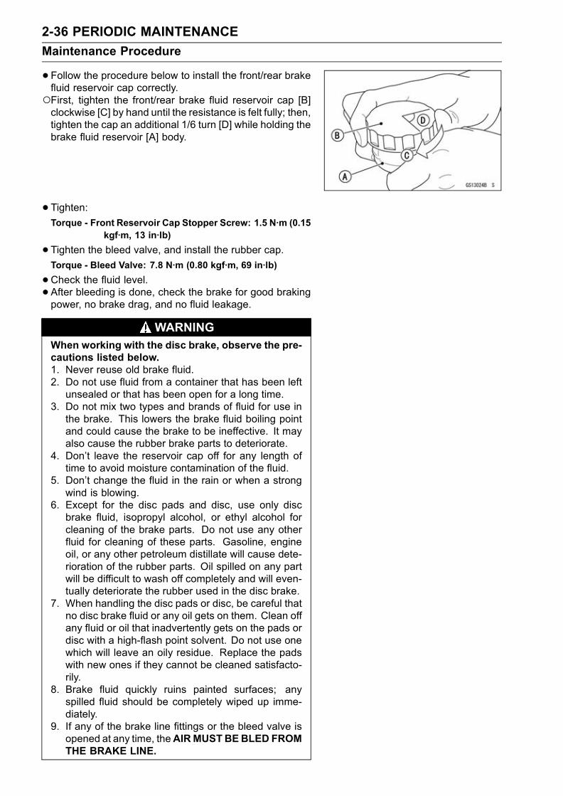
2-36 PERIODIC MAINTENANCE
Maintenance Procedure
•Follow the procedure below to install the front/rear brakefluid reservoir cap correctly.First, tighten the front/rear brake fluid reservoir cap [B]clockwise [C] by hand until the resistance is felt fully; then,tighten the cap an additional 1/6 turn [D] while holding thebrake fluid reservoir [A] body.
• Tighten:Torque - Front Reservoir Cap Stopper Screw: 1.5 N·m (0.15
kgf·m, 13 in·lb)
•Tighten the bleed valve, and install the rubber cap.Torque - Bleed Valve: 7.8 N·m (0.80 kgf·m, 69 in·lb)
•Check the fluid level.• After bleeding is done, check the brake for good brakingpower, no brake drag, and no fluid leakage.
WARNINGWhen working with the disc brake, observe the pre-cautions listed below.1. Never reuse old brake fluid.2. Do not use fluid from a container that has been leftunsealed or that has been open for a long time.
3. Do not mix two types and brands of fluid for use inthe brake. This lowers the brake fluid boiling pointand could cause the brake to be ineffective. It mayalso cause the rubber brake parts to deteriorate.
4. Don’t leave the reservoir cap off for any length oftime to avoid moisture contamination of the fluid.
5. Don’t change the fluid in the rain or when a strongwind is blowing.
6. Except for the disc pads and disc, use only discbrake fluid, isopropyl alcohol, or ethyl alcohol forcleaning of the brake parts. Do not use any otherfluid for cleaning of these parts. Gasoline, engineoil, or any other petroleum distillate will cause dete-rioration of the rubber parts. Oil spilled on any partwill be difficult to wash off completely and will even-tually deteriorate the rubber used in the disc brake.
7. When handling the disc pads or disc, be careful thatno disc brake fluid or any oil gets on them. Clean offany fluid or oil that inadvertently gets on the pads ordisc with a high-flash point solvent. Do not use onewhich will leave an oily residue. Replace the padswith new ones if they cannot be cleaned satisfacto-rily.
8. Brake fluid quickly ruins painted surfaces; anyspilled fluid should be completely wiped up imme-diately.
9. If any of the brake line fittings or the bleed valve isopened at any time, theAIRMUSTBEBLED FROMTHE BRAKE LINE.

PERIODIC MAINTENANCE 2-37
Maintenance Procedure
Brake Hoses and Connections Check
• Inspect the brake hose and fittings for deterioration,cracks and signs of leakage.The high pressure inside the brake line can cause fluid toleak [A] or the hose to burst if the line is not properly main-tained. Bend and twist the rubber hose while examiningit.Replace the hose if any cracks [B] or bulges [C] are no-ticed.Tighten any loose fittings.
SuspensionFront Fork Oil Leak Check
•Visually inspect the front forks [A] for oil leakage, scoringor scratches on the outer surface of the outer tubes.Replace or repair any defective parts, if necessary.
Rear Shock Absorber Oil Leak Check
•Visually inspect the shock absorber [A] for oil leakage.If the oil leakage is found on it, replace the shock absorberwith a new one.
Swingarm Pivot Lubrication
•The grease nipple [A] is equipped for the lubrication ofswingarm bearing. Force grease into the nipple until thegrease comes out from the swingarm pivot, and wipe offany excess of it.
Uni-trak Linkage LubricationIn order for the tie-rod and rocker arm to function safely
and wear slowly, it should be lubricated in accordance withthe Periodic Maintenance Chart.
• For the rocker arm and tie-rod needle bearings, there aregrease nipples [A] on the rocker arm and swingarm forlubrication. Force grease into the nipples until it comesout at both sides of the rocker arm and tie-rod, and wipeoff any excess.

2-38 PERIODIC MAINTENANCE
Maintenance Procedure
SteeringSteering CheckSteering Inspection
•Lift the front wheel off the ground using the jack.Special Tool - Jack: 57001–1238
•With the front wheel pointing straight ahead, alternatelytap each end of the handlebar. The front wheel shouldswing fully left and right from the force of gravity until thefork hits the stop.If the wheel binds or catches before the stop, the steeringis too tight.
• Feel for steering looseness by pushing and pulling theforks.If you feel looseness, the steering is too loose.
NOTEThe cables and wiring will have some effect on the mo-tion of the fork which must be taken into account.Be sure the wires and cables are properly routed.The bearings must be in good condition and properlylubricated in order for any test to be valid.
Steering Adjustment
•Remove:Upper fairing (see Frame chapter)Stem Head Nut[A]Handlebar Position Bolts[B]
• Loosen the upper fork clamp bolts[C].•Remove the stem head[D].
•Remove the steering stem locknut[A] with the steeringstem nut wrench.
Special Tool - Steering Stem Nut Wrench: 57001–1100
•Bend the claw of lock washer[B] faced steering stem lock-nut to straight.
• Remove the lock washer.• Tighten the steering stem nut[C] with the steering stemnut wrench, and loosen it ,tighten it again specified torque.
Torque - Steering Stem Nut:20 N·m (2.0 kgf·m,14.5 ft·lb)
If the steering is too tight, loosen the stem nut a fractionof a turn.If the steering is too loose, tighten the stem nut a fractionof a turn.

PERIODIC MAINTENANCE 2-39
Maintenance Procedure
NOTETurn the stem nut 1/8 turn at a time maximum.
• Install the lock washer so that claw of washer fit the notchof steering stem nut.
• First tighten the steering stem locknut by hand until theresistance is felt fully, then tighten steering stem nut ad-ditional more than two notches so that align the notch ofstem nut and stem locknut.
• Bend the claw of lock washer to the steering stem locknutnotch.
• Install the stem head.
• Tighten:Torque - Upper Fork Clamp Bolts: 20 N·m (2.0 kgf·m, 14.5
ft·lb)Handlebar Position Bolts: 9.8 N·m (1.0 kgf·m, 87in·lb)
Steering Stem Head Nut: 78 N·m (8.0 kgf·m, 58ft·lb)
•Check the steering again.If the steering is still too tight or too loose, repeat the ad-justment.
Steering Stem Bearing Lubrication
•Remove the steering stem (see Steering chapter).
• Using a high flash-point solvent, wash the upper andlower ball bearings in the cages, and wipe the upper andlower outer races, which are press-fitted into the framehead pipe, clean off grease and dirt.
• Visually check the outer races and the ball bearings.Replace the bearing assemblies if they show wear ordamage.
• Pack the upper and lower ball bearings [A] in the cageswith grease, and apply a light coat of grease to the upperand lower outer races.
• Install the steering stem, and adjust the steering.Electrical SystemSpark Plug CheckSpark Plug Cleaning and Inspection
•Remove the spark plug (see Electrical System chapter),and visually inspect.
•Clean the spark plug, preferably in a sandblasting device,and then clean off any abrasive particles. The plug mayalso be cleaned using a high flash-point solvent and a wirebrush or other suitable tool.If the spark plug electrodes are corroded or damaged,or if the insulator is cracked, replace the plug. Use thestandard spark plug or its equivalent.

2-40 PERIODIC MAINTENANCE
Maintenance Procedure
Spark Plug Gap Inspection
•Measure the gap [A] with a wire-type thickness gauge.If the gap is incorrect, carefully bend the side electrode[B] with a suitable tool to obtain the correct gap.
Spark Plug Gap : 0.7 ∼ 0.8 mm (0.028 ∼ 0.031 in.)
CAUTION
Use only the recommended spark plugs (specialmarks ). These spark plugs have special marks [C]on the insulator, as shown. Other spark plugs willwear prematurely.
General LubricationLubrication
•Before lubricating each part, clean off any rusty spots withrust remover and wipe off any grease, oil, dirt, or grime.
• Lubricate the points listed below with indicated lubricant.NOTE
Whenever the vehicle has been operated underwet or rainy conditions, or especially after using ahigh-pressure water spray, perform the general lubri-cation
Pivots: Lubricate with Grease.Clutch LeverBrake LeverBrake PedalSide StandRear Brake Joint Pin
Points: Lubricate with Grease.Clutch Inner Cable Upper and Lower Ends [A]Throttle Inner Cable Upper and Lower EndsChoke Inner Cable Upper and Lower Ends
Cables: Lubricate with Rust InhibiterChoke CableThrottle CablesClutch Cable
• Lubricate the cables by seeping the oil between the cableand housing.The cable may be lubricated by using a commerciallyavailable pressure cable lubricator with an aerosol cablelubricant.

PERIODIC MAINTENANCE 2-41
Maintenance Procedure
•With the cable disconnected at both ends, the inner cableshould move freely [A] within the cable housing.If cable movement is not free after lubricating, if the cableis frayed [B], or if the cable housing is kinked [C], replacethe cable.

2-42 PERIODIC MAINTENANCE
Maintenance Procedure
Nut, Bolts, and Fasteners Tightness CheckTightness Inspection
•Check the tightness of the bolts and nuts listed here. Also,check to see that each cotter pin is in place and in goodcondition.
NOTEFor the engine fasteners, check the tightness of themwhen the engine is cold (at room temperature).
If there are loose fasteners, retorque them to the spec-ified torque following the specified tightening sequence.Refer to the appropriate chapter for torque specifications.If torque specifications are not in the appropriate chapter,see the Standard Torque Table. For each fastener, firstloosen it by 1/2 turn, then tighten it.If cotter pins are damaged, replace them with new ones.
Nut, Bolt and Fastener to be checkedWheels:Front Axle NutFront Axle Clamp BoltRear Axle NutRear Axle Nut Cotter Pin
Brakes:Front Master Cylinder Clamp BoltsCaliper Mounting BoltsRear Master Cylinder Mounting BoltsBrake Lever Pivot NutBrake Pedal BoltBrake Rod Joint Cotter Pin
Suspension:Front Fork Clamp BoltsFront Fender Mounting BoltsRear Shock Absorber Mounting NutsSwingarm Pivot Shaft NutUni-Trak Link Nuts
Steering:Stem Head NutHandlebar Mounting Bolts
Engine:Engine Mounting BoltsCylinder Head BoltsMuffler Mounting BoltsExhaust Manifold Holder NutsMuffler Connecting Clamp BoltClutch Lever Pivot Nut
Others:Side Stand BoltFootpeg Mounting BoltsFootpeg Bracket Mounting Bolts
FUEL SYSTEM (DFI) 3-1
3
Fuel System (DFI)
Table of Contents
Exploded View................................... 3-4Specifications .................................... 3-10Special Tools ..................................... 3-12DFI System........................................ 3-14DFI Servicing Precautions................. 3-20Troubleshooting the DFI System ....... 3-22Outline ............................................ 3-22Inquiries to Rider............................. 3-28
DFI System Troubleshooting Guide .. 3-31ECU................................................... 3-40
ECU Removal .............................. 3-40ECU Installation ........................... 3-40ECU Power Supply Inspection..... 3-41
DFI Power Source ............................. 3-43ECU Fuse Removal ..................... 3-43ECU Fuse Installation .................. 3-43ECU Fuse Inspection ................... 3-43ECU Main Relay Removal ........... 3-43ECU Main Relay Inspection ......... 3-43
FI Indicator LED Light........................ 3-44LED Light Inspection.................... 3-45
Fuel Line............................................ 3-46Fuel Pressure Inspection ............. 3-46Fuel Flow Rate Inspection ........... 3-47
Fuel Pump ......................................... 3-49Fuel Pump Removal .................... 3-49Fuel Pump Installation ................. 3-49Operation Inspection.................... 3-50Operating Voltage Inspection....... 3-50
Fuel Pump Relay .............................. 3-52Fuel Pump Relay Removal .......... 3-52Fuel Pump Relay Inspection ........ 3-52
Fuel Injectors ..................................... 3-54Audible Inspection........................ 3-54Injector Signal Test....................... 3-54Injector Resistance Inspection ..... 3-55Injector Unit Test .......................... 3-55Injector Voltage Inspection........... 3-56Injector Fuel Line Inspection ........ 3-57
Self-Diagnosis ................................... 3-59Self-diagnosis Outline..................... 3-59Self-diagnosis Procedures.............. 3-59Service Code Clearing Procedures 3-60How to Read Service Codes........... 3-62How to Erase Service Codes.......... 3-62Service Code Table......................... 3-63
Backups .......................................... 3-64Main Throttle Sensor (Service Code11)................................................... 3-66Main Throttle SensorRemoval/Adjustment ................. 3-66
Input Voltage Inspection............... 3-66Output Voltage Inspection............ 3-68Resistance Inspection.................. 3-70
Inlet Air Pressure Sensor (ServiceCode 12) ......................................... 3-71Removal....................................... 3-71Installation.................................... 3-71Input Voltage Inspection............... 3-71Output Voltage Inspection............ 3-72
Inlet Air Temperature Sensor (ServiceCode 13) ......................................... 3-76Removal/Installation..................... 3-76Output Voltage Inspection............ 3-76Sensor Resistance Inspection ..... 3-77
Water Temperature Sensor (ServiceCode 14) ......................................... 3-79Removal/Installation..................... 3-79Output Voltage Inspection............ 3-79Sensor Resistance Inspection ..... 3-80
Atmospheric Pressure Sensor(Service Code 15)........................... 3-81Removal....................................... 3-81Installation.................................... 3-81Input Voltage Inspection............... 3-81Output Voltage Inspection............ 3-82
Crankshaft Sensor (Service Code21)................................................... 3-85Crankshaft SensorRemoval/Installation.................. 3-85
Crankshaft Sensor Inspection...... 3-85Camshaft Position Sensor (ServiceCode 23) ......................................... 3-86Camshaft Position SensorRemoval/Installation.................. 3-86
Camshaft Position SensorInspection.................................. 3-86
Speed Sensor (Service Code 24, 25) 3-87Speed SensorRemoval/Installation.................. 3-87
Speed Sensor Inspection............. 3-87Input Voltage Inspection............... 3-87

3-2 FUEL SYSTEM (DFI)
Output Voltage Inspection............ 3-87Vehicle-down Sensor (Service Code31)................................................... 3-89Removal....................................... 3-89Installation.................................... 3-89Inspection..................................... 3-89
Subthrottle Sensor (Service Code32)................................................... 3-92Subthrottle SensorRemoval/Adjustment ................. 3-92
Input Voltage Inspection............... 3-92Output Voltage Inspection............ 3-93Resistance Inspection.................. 3-95
Stick Coils (#1, #2, #3, #4: ServiceCode 51, 52, 53, 54) ....................... 3-96Removal/Installation..................... 3-96Input Voltage Inspection............... 3-96
Subthrottle Valve Actuator (ServiceCode 62) ......................................... 3-98Subthrottle Valve ActuatorRemoval .................................... 3-98
Subthrottle Valve ActuatorInspection.................................. 3-98
Resistance Inspection.................. 3-98Input Voltage Inspection............... 3-99
Throttle Grip and Cables ................... 3-100Free Play Inspection .................... 3-100Free Play Adjustment................... 3-100Cable Installation ......................... 3-100Cable Lubrication ......................... 3-100
Choke Cable...................................... 3-101Free Play Inspection .................... 3-101
Free Play Adjustment................... 3-101Choke Cable Installation .............. 3-101Cable Lubrication ......................... 3-101
Throttle Body Assy ............................ 3-102Idle Speed Inspection .................. 3-102Throttle Bore Cleaning ................. 3-102Synchronization Inspection .......... 3-102Synchronization Adjustment ........ 3-102Throttle Body Assy Removal........ 3-102Throttle Body Assy Installation..... 3-103Throttle Body Assy Disassembly . 3-104Throttle Body Assy Assembly ...... 3-105
Air Line .............................................. 3-106Element Removal......................... 3-106Element Installation...................... 3-106Air Cleaner Element Inspection ... 3-106Oil Draining .................................. 3-106Air Inlet Duct Removal ................. 3-106Air Inlet Duct Installation .............. 3-106
Fuel Tank........................................... 3-107Fuel Tank Removal ...................... 3-107Fuel Tank Installation ................... 3-108Fuel Tank Inspection .................... 3-109Fuel Tank Cleaning ...................... 3-109
Evaporative Emission ControlSystem............................................ 3-110Parts Removal/Installation ........... 3-110Hose Inspection ........................... 3-110Separator Inspection.................... 3-110Separator Operation Test............. 3-111Canister Inspection (CaliforniaModel Only)............................... 3-111

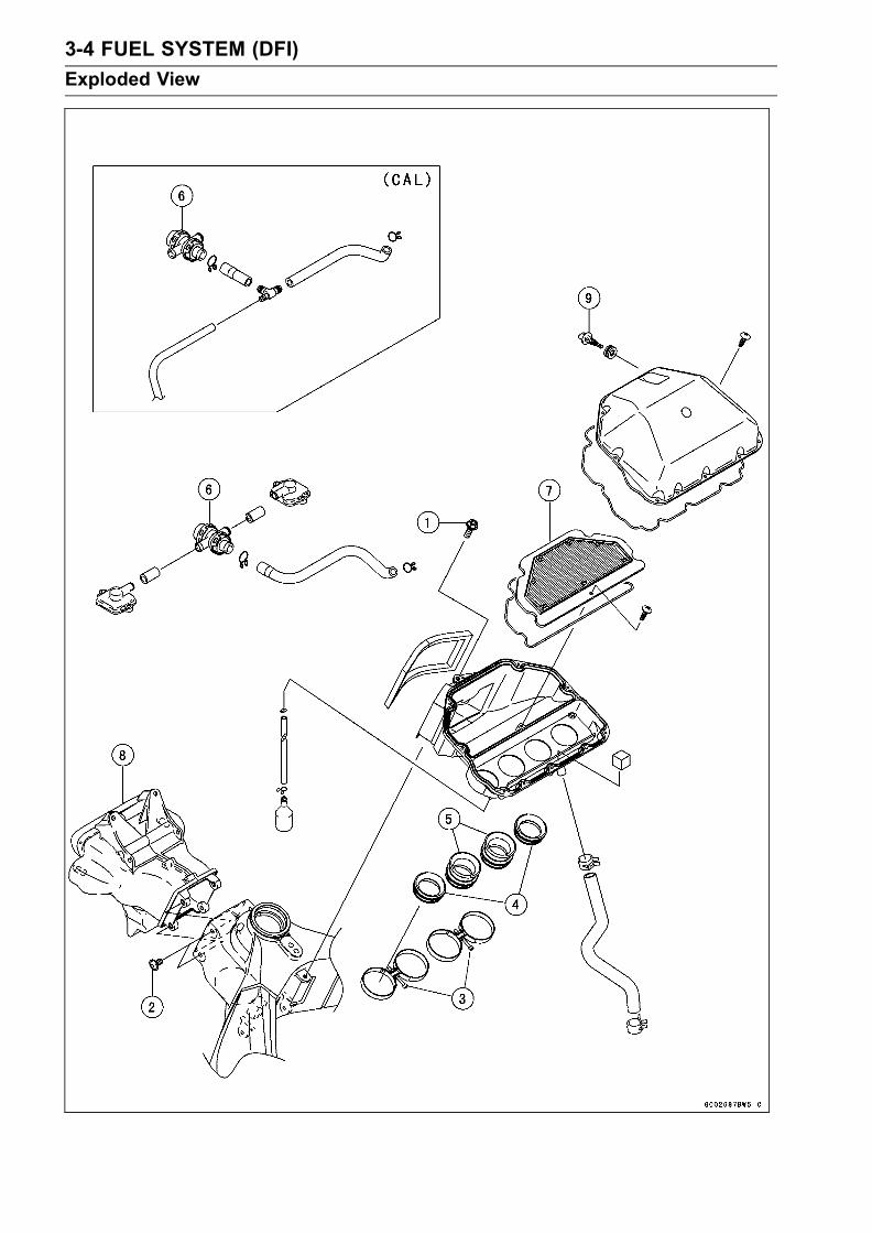
3-4 FUEL SYSTEM (DFI)
Exploded View

FUEL SYSTEM (DFI) 3-5
Exploded View
TorqueNo. Fastener N·m kgf·m ft·lb Remarks
1 Air cleaner housing mounting bolt 6.9 0.70 61 in·lb
2 Air inlet duct mounting bolts 6.9 0.70 61 in·lb
3 Air cleaner housing clamp bolts 2.5 0.25 22 in·lb
No. Parts Remarks
4 Duct (#1, #4) Standard Length 41.3 mm (1.63 in.)
Option Length 21.3 mm (0.84 in.)
5 Duct (#2, #3) Standard Length 81.3 mm (3.20 in.)
Option Length 61.3 mm (2.41 in.)
6. Vacuum Switch-Valve7. Air Cleaner Element8. Inlet Air Duct9. Inlet Air Temperature Sensor
CAL: California model

3-6 FUEL SYSTEM (DFI)
Exploded View

FUEL SYSTEM (DFI) 3-7
Exploded View
TorqueNo. Fastener N·m kgf·m ft·lb Remarks
1 Inlet air pressure sensor screw 4.9 0.50 43 in·lb
2 Atmospheric pressure sensor screw 4.9 0.50 43 in·lb
3 Fuel delivery pipe mounting screws 3.4 0.35 30 in·lb
4Throttle body assembly holder clampbolts
3.0 0.31 27 in·lb
5 Throttle body assembly holder bolts 12 1.2 106 in·lb L
6 Camshaft position sensor 12 1.2 106 in·lb
7 Water temperature sensor 25 2.5 18 SS
8 Vehicle-down sensor 2.0 0.20 17 in·lb
9 Speed sensor mounting bolt 3.9 0.40 35 in·lb L
10 Crankshaft sensor mounting bolts 5.9 0.60 52 in·lb
11. Throttle Cable (accelerator)12. Throttle Cable (decelerator)13. Choke Cable14. Subthrottle Valve Actuator15. Injectors16. Dust Seals17. Bypass Screw18. ECU (Electric Control Unit)L: Apply a non-permanent locking agent.G: Apply grease.SS: Apply silicone sealant (Kawasaki Bond: 56019–120).CL: Apply cable lubricant.R: Replacement Parts
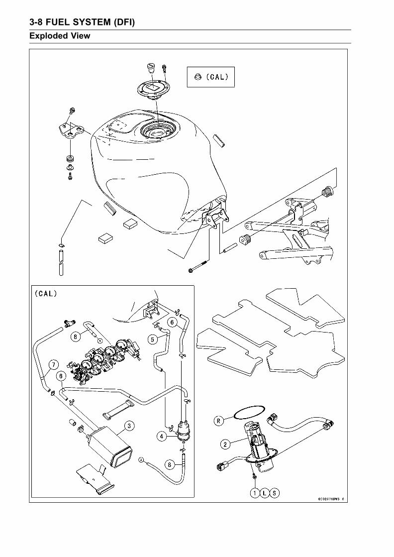
3-8 FUEL SYSTEM (DFI)
Exploded View
FUEL SYSTEM (DFI) 3-9
Exploded View
TorqueNo. Fastener N·m kgf·m ft·lb Remarks
1 Fuel pump bolts 9.8 1.0 87 in·lb
2. Fuel Pump3. Canister4. Separator5. Red6. Blue7. Green8. WhiteL: Apply a non-permanent locking agent.R: Replacement Parts
CAL: California model
3-10 FUEL SYSTEM (DFI)
Specifications
Item Standard
Digital Fuel Injection System
Idle Speed 1 300 ± 50 r/min (rpm)
Throttle Assy:
Type Four barrel type
Bore φ38 mm (1.5 in)
Throttle body vacuum:
ZX636B 24 ± 1.3 kPa (180 ± 10 mmHg)
ZX600K 22 ± 1.3 kPa (165 ± 10 mmHg)
Bypass screws – – –
ECU (Electronic Control Unit):
Make Denso
Type Digital memory type, with built in IC igniter, sealed withresin
Usable engine speed 100 ∼ 14 690 r/min (rpm)Fuel Pressure (high pressure line):
Right after Ignition SW ON, 304 kPa (3.1 kgf/cm², 44 psi) with fuel pump running
with fuel pump running for 3 sec 280 kPa (2.9 kgf/cm², 41 psi) with fuel pump stopped
with engine idling 304 kPa (3.1 kgf/cm², 44 psi) with fuel pump running
Fuel Pump:
Type In-tank pump (in fuel tank), or Wesco pump (friction pump)
Discharge 67 mL (2.27 US oz) or more for 3 seconds
Fuel Injectors:
Type INP–280
Nozzle type One spray type with 4 holes
Resistance about 11.7 ∼ 12.3 Ω at 20°C (68°F)Throttle Sensor: Non-adjustable and non-removable
Input voltage 4.75 ∼ 5.25 V DC between BL and BR/BK leadsOutput voltage 1.02 ∼ 4.62 V DC between Y/W and BR/BK leads (at idle
throttle opening to full throttle opening)
Resistance 4 ∼ 6 kΩInlet Air Pressure Sensor/
Atmospheric Pressure Sensor:
Input voltage 4.75 ∼ 5.25 V DC between BL and BR/BK leadsOutput voltage 3.80 ∼ 4.20 V DC at standard atmospheric pressure (see
this text for details)
Inlet Air Temperature Sensor:
Resistance 1.6 ∼ 3.7 kΩ at 20°C (68°F)0.24 ∼ 0.43 kΩ at 80°C (176°F)
Output voltage at ECU about 2.25 ∼ 2.50 V @20°C (68°F)Water Temperature Sensor:
Resistance see Electrical System chapter
Output voltage at ECU about 2.80 ∼ 2.97 V @20°C (68°F)Speed Sensor:
Input voltage at sensor about 9 ∼ 11 V DC at Ignition SW ON
Output voltage at sensor about 0.05 ∼ 0.07 V DC at Ignition SW ON and 0 km/h
FUEL SYSTEM (DFI) 3-11
Specifications
Item Standard
Vehicle-down Sensor:
Detection method Magnetic flux detection method
Detection angle More than 60 ∼ 70° for each bankDetection time Within 0.5 ∼ 1.0 sec.Output voltage with the sensor tilted 60 ∼ 70° or more: 3.7 ∼ 4.4 V
with sensor arrow mark pointed up: 0.4 ∼ 1.4 VSubthrottle Sensor: Non-adjustable and non-removal
Input Voltage 4.75 ∼ 5.25 V DC between BL and BR/BK leads
Output Voltage1.08 ∼ 4.60 V DC between BR and BR/BK leads (at idlethrottle opening to full throttle opening)
Resistance 4 ∼ 6 kΩSubthrottle Valve Actuator:
Resistance about 5 ∼ 7 kΩInput voltage about 8.5 ∼ 10.5 V DC
Throttle Grip and Cables
Throttle grip free play 2 ∼ 3 mm (0.08 ∼ 0.12 in)Choke Cable
Choke cable free play 2 ∼ 3 mm (0.08 ∼ 0.12 in)

3-12 FUEL SYSTEM (DFI)
Special Tools
Oil Pressure Gauge:57001–125
Carburetor Drain Plug Wrench, Hex 3:57001–1269
Fork Oil Level Gauge:57001–1290
Pilot Screw Adjuster, C:57001–1292
Hand Tester:57001–1394
Throttle Sensor Setting Adapter:57001–1400
Fuel Pressure Gauge Adapter:57001–1417
Needle Adapter Set:57001–1457
Throttle Sensor Setting Adapter:57001–1538
Sensor Harness Adapter:57001–1561
FUEL SYSTEM (DFI) 3-13
Special Tools
Kawasaki Bond (Silicone Sealant):56019–120

3-14 FUEL SYSTEM (DFI)
DFI System
DFI System

FUEL SYSTEM (DFI) 3-15
DFI System
1. ECU (Electric Control Unit)2. Crankshaft Sensor3. Camshaft Position Sensor4. Main Throttle Sensor5. Subthrottle Sensor6. Subthrottle Valve Actuator7. Inlet Air Pressure Sensor8. Atmospheric Pressure Sensor9. Water Temperature Sensor10. Inlet Air Temperature Sensor11. Vehicle-down Sensor12. Injectors13. Delivery Pipe14. Pressure Regulator15. Fuel Filter16. Fuel Pump17. Speed Sensor18. Battery19. Ignition Switch20. Starter Locknut & Engine Stop Switch21. Starter Relay22. Tachometer23. FI Indicator LED Light24. Inlet Air Duct25. Frame26. Air Cleaner Element27. Fuel Tank28. Air Flow29. Fuel Flow

3-16 FUEL SYSTEM (DFI)
DFI System
DFI System Wiring Diagram

FUEL SYSTEM (DFI) 3-17
DFI System
Part Name1. Subthrottle Valve Actuator2. Injector #13. Injector #24. Injector #35. Injector #46. Water Temperature Sensor7. Speed Sensor8. Inlet Air Temperature Sensor9. Atmospheric Pressure Sensor10. Subthrottle Sensor11. Main Throttle Sensor12. Inlet Air Pressure Sensor13. Crankshaft Sensor14. Camshaft Position Sensor15. ECU (Electric Control Unit)16. Water Temperature Gauge17. Speedometer18. FI Indicator LED Light19. Stick Coil #120. Stick Coil #221. Stick Coil #322. Stick Coil #423. Starter Button24. Engine Stop Switch25. Ignition Switch26. Junction Box27. Ignition Fuse 10A28. ECU Main Relay29. Fuel Pump Relay30. ECU Fuse 15A31. Vehicle-down Sensor32. Main Fuse 30A33. Battery34. Fuel Pump35. Self-diagnosis Terminal
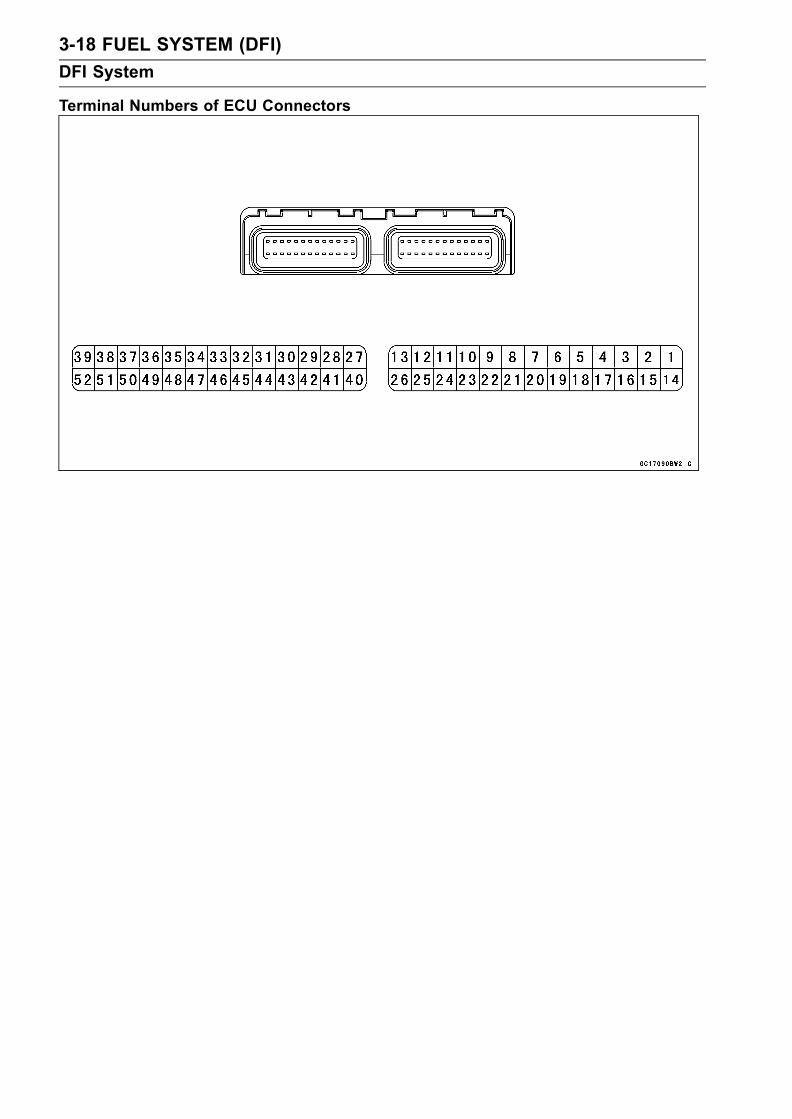
3-18 FUEL SYSTEM (DFI)
DFI System
Terminal Numbers of ECU Connectors

FUEL SYSTEM (DFI) 3-19
DFI System
Terminal Names1. Power Supply to Sensors2. Main Throttle Sensor Output Signal3. Subthrottle Sensor Output Signal4. Atmospheric Pressure Sensor Output Signal5. Water Temperature Sensor Output Signal6. Unused7. Ignition Switch Output Signal8. Unused9. Camshaft Position Sensor (+) Output Signal10. Unused11. Crankshaft Sensor (+) Output Signal12. Unused13. Power Supply to ECU (from ECU Mine Relay)14. Ground to Sensors15. Unused16. Vehicle-down Sensor Output Signal17. Inlet Air Pressure Sensor Output Signal18. Inlet Air Temperature Sensor Output Signal19. Unused20. Speed Sensor Output Signal21. Unused22. Camshaft Position Sensor (–) Output Signal23. Unused24. Crankshaft Sensor (–) Output Signal25. Unused26. Ground to ECU27. Engine Stop Switch Output Signal28. Starter Lockout Switch Output Signal29. Starter Button Output Signal30. Fuel Pump Relay Output Signal31. Subthrottle Valve Actuator Output Signal 132. Subthrottle Valve Actuator Output Signal 233. Unused34. Tachometer Output Signal35. Injector #2 Output Signal36. Injector #1 Output Signal37. Stick Coil #3 Output Signal38. Stick Coil #2 Output Signal39. Stick Coil #1 Output Signal40. Input Signal for Engine Stop41. Self- diagnosis Terminal42. Unused (Mode Switch)43. Power Supply to ECU (from Battery)44. Subthrottle Valve Actuator Output Signal 345. Subthrottle Valve Actuator Output Signal 446. External Diagnosis System Signal47. FI Indicator LED Light48. Injector #4 Output Signal49. Injector #3 Output Signal50. Ground for Fuel System51. Ground for Ignition System52. Stick Coil #4 Output Signal

3-20 FUEL SYSTEM (DFI)
DFI Servicing Precautions
There are a number of important precautions that shouldbe followed servicing the DFI system.
This DFI system is designed to be used with a 12 V sealedbattery as its power source. Do not use any other batteryexcept for a 12 V sealed battery as a power source.Do not reverse the battery cable connections. This willdamage the ECU.To prevent damage to the DFI parts, do not disconnect thebattery cables or any other electrical connections whenthe ignition SW (switch) is on, or while the engine is run-ning.Take care not to short the leads that are directly con-nected to the battery positive (+) terminal to the chassisground.When charging, remove the battery from the motorcycle.This is to prevent ECU damage by excessive voltage.Whenever the DFI electrical connections are to be discon-nected, first turn off the ignition SW (switch). Conversely,make sure that all the DFI electrical connections are firmlyreconnected before starting the engine.Do not turn the ignition SW ON while any of the DFI elec-trical connectors are disconnected. The ECU memorizesservice codes.Do not spray water on the electrical parts, DFI parts, con-nectors, leads, and wiring.If a transceiver is installed on the motorcycle, make surethat the operation of the DFI system is not influenced byelectric wave radiated from the antenna. Check operationof the system with the engine at idle. Locate the antennaas far as possible away from the ECU.When any fuel hose is disconnected, do not turn on theignition SW. Otherwise, the fuel pump will operate andfuel will spout from the fuel hose.Do not operate the fuel pump if the pump is completelydry. This is to prevent pump seizure.Before removing the fuel system parts, blow the outer sur-faces of these parts clean with compressed air.When any fuel hose is disconnected, fuel may spout outby residual pressure in the fuel line. Cover the hose jointwith a piece of clean cloth to prevent fuel spillage.When installing the fuel hoses, avoid sharp bending, kink-ing, flattening or twisting, and route the fuel hoses with aminimum of bending so that the fuel flow will not be ob-structed.Route the hoses according to Cable, Wire, and HoseRouting section in the General Information chapter.To prevent corrosion and deposits in the fuel system, donot add to fuel any fuel antifreeze chemicals.Replace the fuel hose if it has been sharply bent or kinked.

FUEL SYSTEM (DFI) 3-21
DFI Servicing Precautions
The fuel hose [A] is designed to be used through out themotorcycle’s life without any maintenance, however, if themotorcycle is not properly handled, the high pressure in-side the fuel line can cause fuel to leak or the hose toburst. Bend and twist the fuel hose while examining it.Replace the hose if any cracks or bulges are noticed.
To maintain the correct fuel/air mixture (F/A), there mustbe no inlet air leaks in the DFI system. Be sure to installthe oil filler plug [A] after filling the engine oil.Clutch Cover [B]
Torque - Oil Filler Plug: 1.5 N·m (0.15 kgf·m, 13 in·lb)

3-22 FUEL SYSTEM (DFI)
Troubleshooting the DFI System
OutlineWhen an abnormality in the system occurs, the FI indica-
tor LED (Light Emitting Diode) light goes on to alert the rideron the meter panel. In addition, the condition of the problemis stored in the memory of the ECU (electronic control unit).With the engine stopped and turned in the self-diagnosismode, the service code [A] is indicated by the number oftimes the FI indicator LED light blinks.When due to a malfunction, the FI indicator LED light re-
mains lit, ask the rider about the conditions [B] under whichthe problem occurred and try to determine the cause [C].Don’t rely solely on the DFI self-diagnosis function, usecommon sense; first conduct a pre-diagnosis inspection,check the ECU for ground and power supply, the fuel line forno fuel leaks, and for correct pressure. The pre-diagnosisitems are not indicated by the FI indicator LED light.
Even when the DFI system is operating normally, the FIindicator LED light [A] may light up under strong electri-cal interference. No remedy needed. Turn the ignition SW(switch) OFF to stop the indicator light.When the FI indicator LED light goes on and the motor-
cycle is brought in for repair, check the service codes.When the repair has been done, the LED light doesn’t go
on. But the service codes stored in memory are not erasedto preserve the problem history, and the LED light can dis-play the codes in the self-diagnosis mode. The problemhistory is referred when solving unstable problems.
Much of the DFI system troubleshooting work consistsof confirming continuity of the wiring. The DFI parts areassembled and adjusted with precision, and it is impossibleto disassemble or repair them.
•When checking the DFI parts, use a digital meter whichcan be read two decimal place voltage or resistance.Remove:Seats (see Frame chapter)
The DFI part connectors have seals, including the ECU.When measuring the input or output voltage with theconnector joined, use the needle adapter set. Insert theneedle adapter inside the seal until the needle adapterreaches the terminal (for example, ECU is shown.).Digital Meter [A]
Special Tool - Needle Adapter Set: 57001–1457
CAUTION
Tape the leads to prevent short circuit of the leads.

FUEL SYSTEM (DFI) 3-23
Troubleshooting the DFI System
After measurement, remove the needle adapters and ap-ply silicone sealant to the seals [A] of the connector [B]for waterproofing.
Silicone Sealant (Kawasaki Bond: 56019-120)
Seals of Connector
•Always check battery condition before replacing the DFIparts. A fully charged battery is a must for conductingaccurate tests of the DFI system.
• Trouble may involve one or in some cases all items.Never replace a defective part without determining whatCAUSED the problem. If the problem was caused bysome other item or items, they too must be repaired orreplaced, or the new replacement part will soon fail again
•Measure coil winding resistance when the DFI part is cold(at room temperature)
•Do not adjust or remove the throttle sensor.•Do not directly connect a 12 V battery to a fuel injector.Insert a resistor (5 ∼ 7 Ω ) or a bulb (12 V × 3 ∼ 3.4 W) inseries between the battery and the injector.
• The DFI parts have been adjusted and set with precision.Therefore, they should be handled carefully, never strikesharply, as with a hammer, or allowed to drop on a hardsurface. Such a shock to the parts can damage them.
•Check wiring and connections from the ECU connectorto the suspected faulty DFI parts, using the hand tester(special tool, analog tester) rather than a digital tester.
Special Tool - Hand Tester: 57001–1394
•Make sure all connectors in the circuit are clean and tight,and examine wires for signs of burning, fraying, etc. Dete-riorated leads and bad connections can cause reappear-ance of problems and unstable operation of the DFI sys-tem.If any wiring is deteriorated, replace the wiring.
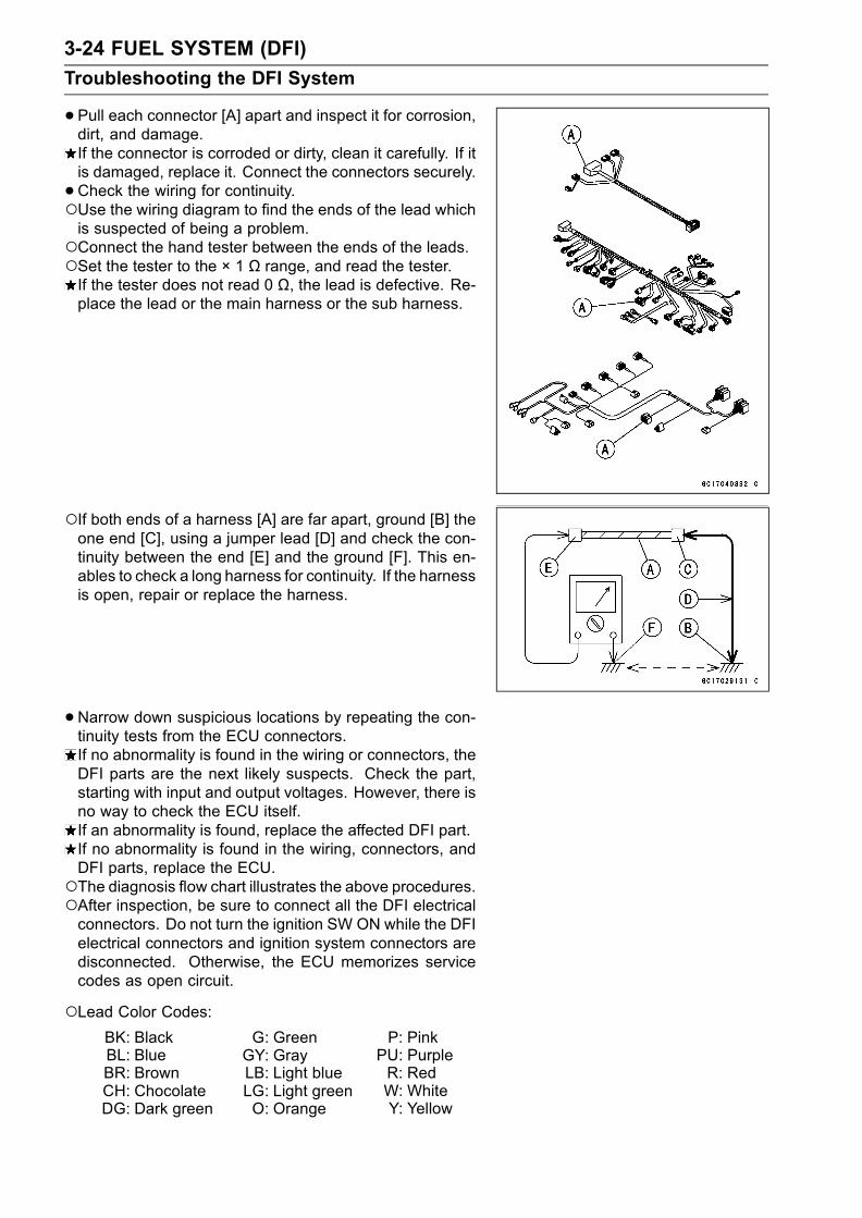
3-24 FUEL SYSTEM (DFI)
Troubleshooting the DFI System
•Pull each connector [A] apart and inspect it for corrosion,dirt, and damage.If the connector is corroded or dirty, clean it carefully. If itis damaged, replace it. Connect the connectors securely.
•Check the wiring for continuity.Use the wiring diagram to find the ends of the lead whichis suspected of being a problem.Connect the hand tester between the ends of the leads.Set the tester to the × 1 Ω range, and read the tester.If the tester does not read 0 Ω, the lead is defective. Re-place the lead or the main harness or the sub harness.
If both ends of a harness [A] are far apart, ground [B] theone end [C], using a jumper lead [D] and check the con-tinuity between the end [E] and the ground [F]. This en-ables to check a long harness for continuity. If the harnessis open, repair or replace the harness.
•Narrow down suspicious locations by repeating the con-tinuity tests from the ECU connectors.If no abnormality is found in the wiring or connectors, theDFI parts are the next likely suspects. Check the part,starting with input and output voltages. However, there isno way to check the ECU itself.If an abnormality is found, replace the affected DFI part.If no abnormality is found in the wiring, connectors, andDFI parts, replace the ECU.The diagnosis flow chart illustrates the above procedures.After inspection, be sure to connect all the DFI electricalconnectors. Do not turn the ignition SW ON while the DFIelectrical connectors and ignition system connectors aredisconnected. Otherwise, the ECU memorizes servicecodes as open circuit.
Lead Color Codes:BK: Black G: Green P: PinkBL: Blue GY: Gray PU: PurpleBR: Brown LB: Light blue R: RedCH: Chocolate LG: Light green W: WhiteDG: Dark green O: Orange Y: Yellow

FUEL SYSTEM (DFI) 3-25
Troubleshooting the DFI System
Electrical Connectors:Female Connectors [A]
Male Connectors [B]

3-26 FUEL SYSTEM (DFI)
Troubleshooting the DFI System
DFI Diagnosis Flow Chart

FUEL SYSTEM (DFI) 3-27
Troubleshooting the DFI System
Notes:OK: No problem.NG: Problem exists.
1. Inspection starts.• An abnormality occurs in the DFI system, and the FI indicator LED light goes on to alert the rider.• Bring the motorcycle into the shop.
2. Confirm problems.• Reproduce the problems if possible.
3. Conduct pre-diagnosis inspection.• The pre-diagnosis inspection items are not handled by self-diagnosis. Check the problem beforeself-diagnosis, considering the symptoms of the problem.• Pre-diagnosis Inspection Items
ECU Power Supply InspectionECU Fuse InspectionECU Main Relay InspectionFI Indicator LED Light Operation InspectionFuel Pressure InspectionFuel Flow Rate InspectionFuel Line Leakage InspectionFuel Injectors and Fuel Pump Leakage Inspection
4. Conduct self-diagnosis.• Enter the self-diagnosis mode and count the blinks of the FI indicator LED light to read theservice code.
5. Check items.• Decide the faulty part, referring to the problem chart.• Decide the check procedure for each faulty part, referring to each section (Fault Inspection 11
∼ 62).
6. Operation check.• Make sure the FI indicator LED light goes off.• If the problem is related to startability or idle stability, idle the engine to confirm that the DFIsystem and the ignition system are operating correctly.• If the problem is related to driveability, ride the motorcycle at 30 km/h (18 mph) or above toconfirm that the DFI system and the ignition system are operating correctly.

3-28 FUEL SYSTEM (DFI)
Troubleshooting the DFI System
Inquiries to RiderEach rider reacts to problems in different ways, so it is important to confirm what kind of symptomsthe rider has encountered.Try to find out exactly what problem occurred under exactly what conditions by asking the rider;knowing this information may help you reproduce the problem.The diagnosis sheet will help prevent you from overlooking any areas, and will help you decide if itis a DFI system problem, or a general engine problem.
Diagnosis Keys
What – Motorcycle modelWhen – Date (frequency of problem)Where – Road conditions, altitudeHow – Riding conditions
Environment

FUEL SYSTEM (DFI) 3-29
Troubleshooting the DFI System
Sample Diagnosis SheetRider name: Registration No. (license plate No.): Year of initial registration:
Model: Engine No.: Frame No.:
Date problem occured: Mileage:
Environment when problem occurred.
Weather fine, cloudy, rain, snow, always, other:Temperature hot, warm, cold, very cold, alwaysProblem chronic, often, oncefrequency
Road street, highway, mountain road ( uphill, downhill), bumpy, pebbleAltitude normal, high (about 1000 m or more)
Motorcycle conditions when problem occurred.
FI indicator light up immediately after ignition SW ON, and goes off after 1 ∼ 2 secondsLED light (normal).
lights blinks immediately after ignition SW ON, and stays on (DFI problem)
lights up immediately after ignition SW ON, but goes off after about 10
seconds (DFI problem).
unlights (LED light, ECU or its wiring fault). sometimes lights up (probably wiring fault).
Starting starter motor not rotating.difficulty starter motor rotating but engine doesn’t turn over.
starter motor and engine don’t turn over. no fuel flow ( no fuel in tank, no fuel pump sound). engine flooded (do not crank engine with throttle opened, which promotes engineflooding).
no spark. choke lever is not pulled fully when using the lever (pull it fully when using). other:
Engine stalls right after starting. when opening throttle grip. when closing throttle grip. when moving off. when stopping the motorcycle. when cruising. other:

3-30 FUEL SYSTEM (DFI)
Troubleshooting the DFI System
Poor running choke lever pulled out fully (push it in fully).at low speed very low choke speed.
very low idle speed, very high idle speed, rough idle speed. battery voltage is low (charge the battery). spark plug loose (tighten it). spark plug dirty, broken, or gap maladjusted (remedy it). backfiring. afterfiring. hesitation when acceleration. engine oil viscosity too high. brake dragging. engine overheating. clutch slipping. other:
Poor running choke lever pulled out fully (push it in fully).or no power spark plug loose (tighten it).at high speed spark plug dirty, broken, or gap maladjusted (remedy it).
spark plug incorrect (replace it). knocking (fuel poor quality or incorrect,→ use high-octane gasoline).
brake dragging. clutch slipping. engine overheating. engine oil level too high. engine oil viscosity too high. other:

FUEL SYSTEM (DFI) 3-31
DFI System Troubleshooting Guide
NOTEThis is not an exhaustive list, giving every possible cause for each problem listed. It is meantsimply as a rough guide to assist the troubleshooting for some of the more common difficulties.The ECU may be involved in the DFI electrical and ignition system troubles. If these parts andcircuits are checked out good, be sure to check the ECU for ground and power supply. If theground and power supply are checked good, replace the ECU.
Engine Doesn’t Start, Starting DifficultySymptoms or possible Causes Actions (chapter)
Starter motor not rotating:
Ignition and engine stop switches not ON Turn both switches ON.
Starter lockout switch or neutral switch trouble Inspect (see chapter 16)
Starter motor trouble Inspect (see chapter 16).
Battery voltage low Inspect and charge (see chapter 16).
Starter relays not contacting or operating Inspect the starter relay (see chapter 16).
Starter button not contacting Inspect and replace (see chapter 16).
Starter system wiring open or shorted Inspect the wiring (see chapter 16).
Ignition switch trouble Inspect and replace (see chapter 16).
Engine stop switch trouble Inspect and repair or replace (see chapter 16).
Main 30A or ignition fuse blown Inspect and replace (see chapter 16).
Starter motor rotating but engine doesn’tturn over :
Starter clutch trouble Inspect (see chapter 9).
Starter idle gear trouble Inspect (see chapter 9).
Engine won’t turn over :
Valve seizure Inspect and replace (see chapter 5).
Cylinder, piston seizure Inspect and replace (see chapter 5).
Camshaft seizure Inspect and replace (see chapter 5).
Connecting rod small end seizure Inspect and replace (see chapter 9).
Connecting rod big end seizure Inspect and replace (see chapter 9).
Crankshaft seizure Inspect and replace (see chapter 9).
Transmission gear or bearing seizure Inspect and replace (see chapter 9).
Balancer bearing seizure Inspect and replace (see chapter 9).
No fuel flow :
No or little fuel in tank Supply fuel (see Owner’s Manual).
Fuel pump not rotating Inspect (see chapter 3).
Fuel injector trouble Inspect and replace (see chapter 3).
Fuel tank air vent obstructed Inspect and repair (see chapter 3).
Fuel filter or pump screen clogged Inspect and replace fuel pump (see chapter 3).
Fuel pressure regulator clogged Inspect and replace fuel pump (see chapter 3).
Fuel line clogged Inspect and repair (see chapter 3).
Engine flooded :
Spark plug dirty, broken or gap maladjustedClean spark plugs and adjust plug gap (seechapter 2).
Starting technique faultyWhen flooded, don’t crank engine with throttlefully opened.
No spark or spark weak :

3-32 FUEL SYSTEM (DFI)
DFI System Troubleshooting Guide
Symptoms or possible Causes Actions (chapter)
Ignition and engine stop switches not ON Turn both switches ON .
Clutch lever not pulled in and gear not in neutralwhether sidestand up or not
Pull the lever in and shift the gear in neutral.
Though clutch lever pulled in, sidestand up andgear not in neutral
Sidestand down and clutch lever pulled inwhether gear in neutral or not
Vehicle-down sensor coming off Reinstall (see chapter 3).
Vehicle-down sensor trouble Inspect (see chapter 3) .
ECU ground or power supply trouble Inspect (see chapter 3) .
Battery voltage low Inspect and charge (see chapter 16).
Spark plug dirty, broken or gap maladjustedClean spark plug and adjust plug gap (seechapter 2).
Spark plug cap trouble Inspect stick coil (see chaper 16).
Spark plug cap shorted or not in good contact Reinstall or inspect stick coil (see chapter 16).
Spark plug incorrect Replace it with the correct plug (see chapter 16).
IC igniter in ECU trouble Inspect (see chapter 16).
Neutral, starter lockout or sidestand switchtrouble
Inspect each switch (see chapter 16).
Crankshaft sensor trouble Inspect (see chapter 16).
Stick coil trouble Inspect (see chapter 16).
Ignition switch shorted Inspect and replace (see chapter 16).
Engine stop switch shorted Inspect and repair or replace (see chapter 16) .
Starter system wiring shorted or open Inspect and repair or replace (see chapter 16).
Main 30A or ignition fuse blown Inspect and replace (see chapter 16).
Fuel/air mixture incorrect :
Air cleaner clogged, poorly sealed or missing Clean or reinstall (see chapter 3).
Leak from oil filler cap, crankcase breather hoseor air cleaner drain hose
Inspect and repair or replace (see chapter 3).
Water or foreign matter in fuelChange fuel. Inspect and clean fuel system (seechapter 3).
Fuel pressure regulator troubleInspect fuel pressure and replace fuel pump (seechapter 3).
Main throttle sensor trouble Inspect (see chapter 3).
Fuel pressure may be low Inspect (see chapter 3).
Fuel pump trouble Inspect (see chapter 3).
Fuel injector trouble Inspect (see chapter 3).
Inlet air pressure sensor trouble Inspect (see chapter 3).
Atmospheric pressure sensor trouble Inspect (see chapter 3).
Inlet air temperature sensor trouble Inspect (see chapter 3).
Water temperature sensor trouble Inspect (see chapter 3).
Crankshaft sensor trouble Inspect (see chapter 3).
Compression low :
Spark plug loose Reinstall (see chapter 16).
Cylinder head not sufficiently tightened down Tighten (see chapter 5).
Cylinder, piston worn Inspect and replace (see chapter 5).
Piston ring bad (worn, weak, broken or sticking) Inspect and replace (see chapter 5).
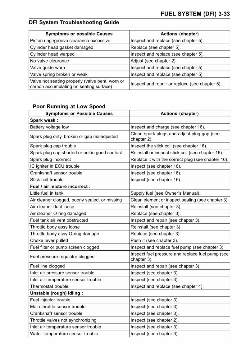
FUEL SYSTEM (DFI) 3-33
DFI System Troubleshooting Guide
Symptoms or possible Causes Actions (chapter)
Piston ring /groove clearance excessive Inspect and replace (see chapter 5).
Cylinder head gasket damaged Replace (see chapter 5).
Cylinder head warped Inspect and replace (see chapter 5).
No valve clearance Adjust (see chapter 2).
Valve guide worn Inspect and replace (see chapter 5).
Valve spring broken or weak Inspect and replace (see chapter 5).
Valve not seating properly (valve bent, worn orcarbon accumulating on seating surface)
Inspect and repair or replace (see chapter 5).
Poor Running at Low SpeedSymptoms or Possible Causes Actions (chapter)
Spark weak :
Battery voltage low Inspect and charge (see chapter 16).
Spark plug dirty, broken or gap maladjustedClean spark plugs and adjust plug gap (seechapter 2).
Spark plug cap trouble Inspect the stick coil (see chapter 16).
Spark plug cap shorted or not in good contact Reinstall or inspect stick coil (see chapter 16).
Spark plug incorrect Replace it with the correct plug (see chapter 16).
IC igniter in ECU trouble Inspect (see chapter 16).
Crankshaft sensor trouble Inspect (see chapter 16).
Stick coil trouble Inspect (see chapter 16).
Fuel / air mixture incorrect :
Little fuel in tank Supply fuel (see Owner’s Manual).
Air cleaner clogged, poorly sealed, or missing Clean element or inspect sealing (see chapter 3).
Air cleaner duct loose Reinstall (see chapter 3).
Air cleaner O-ring damaged Replace (see chapter 3).
Fuel tank air vent obstructed Inspect and repair (see chapter 3).
Throttle body assy loose Reinstall (see chapter 3).
Throttle body assy O-ring damage Replace (see chapter 3).
Choke lever pulled Push it (see chapter 3).
Fuel filter or pump screen clogged Inspect and replace fuel pump (see chapter 3).
Fuel pressure regulator cloggedInspect fuel pressure and replace fuel pump (seechapter 3).
Fuel line clogged Inspect and repair (see chapter 3).
Inlet air pressure sensor trouble Inspect (see chapter 3).
Inlet air temperature sensor trouble Inspect (see chapter 3).
Thermostat trouble Inspect and replace (see chapter 4).
Unstable (rough) idling :
Fuel injector trouble Inspect (see chapter 3).
Main throttle sensor trouble Inspect (see chapter 3).
Crankshaft sensor trouble Inspect (see chapter 3).
Throttle valves not synchronizing Inspect (see chapter 2).
Inlet air temperature sensor trouble Inspect (see chapter 3).
Water temperature sensor trouble Inspect (see chapter 3).

3-34 FUEL SYSTEM (DFI)
DFI System Troubleshooting Guide
Symptoms or Possible Causes Actions (chapter)
Atmospheric pressure sensor trouble Inspect (see chapter 3).
Fuel pressure too low or too high Inspect (see chapter 3).
Battery voltage low Inspect and charge (see chapter 16).
Incorrect idle speed :
Water temperature sensor trouble Inspect (see chapter 3).
Main throttle sensor trouble Inspect (see chapter 3).
Engine stalls easily :
Fuel pump trouble Inspect (see chapter 3).
Fuel injector trouble Inspect (see chapter 3).
Main throttle sensor trouble Inspect (see chapter 3).
Camshaft position sensor trouble Inspect (see chapter 3).
Fuel pressure too low or too high Inspect (see chapter 3).
Inlet air pressure sensor trouble Inspect (see chapter 3).
Water temperature sensor trouble Inspect (see chapter 3).
Inlet air temperature sensor trouble Inspect (see chapter 3).
Fuel line clogged Inspect and repair (see chapter 3).
Fuel pressure too low or too high Inspect (see chapter 3).
Fuel pressure regulator troubleInspect fuel pressure and replace fuel pump (seechapter 3).
Crankshaft sensor trouble Inspect (see chapter 16).
Stick coil trouble Inspect (see chapter 16).
Compression Low :
Spark plug loose Reinstall (see chapter 16).
Cylinder head not sufficiently tightened down Tighten (see chapter 5).
No valve clearance Adjust (see chapter 2).
Cylinder, piston worn Inspect and replace (see chapter 5).
Piston ring bad (worn, weak, broken or sticking ) Inspect and replace (see chapter 5).
Piston ring /groove clearance excessive Inspect and replace (see chapter 5).
Cylinder head gasket damaged Replace (see chapter 5).
Cylinder head warped Inspect and replace (see chapter 5).
Valve guide worn or stem seal damaged Inspect and replace (see chapter 5).
Valve spring broken or weak Inspect and replace (see chapter 5).
Valve not seating properly (valve bent, worn orcarbon accumulating on seating surface)
Inspect and repair or replace (see chapter 5).
Camshaft cam worn Inspect and replace (see chapter 5).
Hesitation :
Too low fuel pressure Inspect (see chapter 3).
Clogged fuel line Inspect and repair (see chapter 3).
Cracked or obstructed inlet air pressure sensorhose
Inspect and repair or replace (see chapter 3).
Fuel pump trouble Inspect (see chapter 3).
Fuel injector trouble Inspect (see chapter 3).
Inlet air temperature sensor trouble Inspect (see chapter 3).
Main throttle sensor trouble Inspect (see chapter 3).
Subthrottle sensor trouble Inspect (see chapter 3).

FUEL SYSTEM (DFI) 3-35
DFI System Troubleshooting Guide
Symptoms or Possible Causes Actions (chapter)
Subthrottle valve actuator trouble Inspect (see chapter 3).
Water temperature sensor trouble Inspect (see chapter 3).
Atmospheric pressure sensor trouble Inspect (see chapter 3).
Inlet air pressure sensor trouble Inspect (see chapter 3).
Loose injector connectors Remedy (see chapter 3).
Crankshaft sensor trouble Inspect and repair or replace (see chapter 16).
Stick coil trouble Inspect and repair or replace (see chapter 16).
Loose terminal of battery (–) lead or engineground lead
Inspect and repair (see chapter 16).
Delay of ignition timingInspect crankshaft sensor and IC igniter in ECU(see chapter 16).
Poor acceleration :
Choke lever pulled Push it (see chapter 3).
Too low fuel pressure Inspect (see chapter 3).
Water or foreign matter in fuelChange fuel. Inspect and clean fuel system (seechapter 3).
Clogged fuel filter or pump screen Inspect and replace fuel pump (see chapter 3).
Fuel pump trouble Inspect (see chapter 3).
Fuel injector trouble Inspect (see chapter 3).
Inlet air temperature sensor trouble Inspect (see chapter 3).
Water temperature sensor trouble Inspect (see chapter 3).
Atmospheric pressure sensor trouble Inspect (see chapter 3).
Subthrottle sensor trouble Inspect (see chapter 3).
Subthrottle valve actuator trouble Inspect (see chapter 3).
Stick coil trouble Inspect and replace (see chapter 16).
Engine oil level to high Repair (see chapter 7).
Spark plug dirty, broken or gap maladjustedClean spark plugs and adjust plug gap (seechapter 2).
Stumble :
Too low fuel pressure Inspect (see chapter 3).
Fuel injector trouble Inspect (see chapter 3).
Main throttle sensor malfunction Inspect (see chapter 3).
Subthrottle sensor trouble Inspect (see chapter 3).
Subthrottle valve actuator trouble Inspect (see chapter 3).
Water temperature sensor trouble Inspect (see chapter 3).
Inlet air pressure sensor trouble Inspect (see chapter 3).
Surge :
Unstable fuel pressureFuel pressure regulator trouble (Inspect andreplace fuel pump) or kinked fuel line (Inspectand repair fuel line) (see chapter 3).
Fuel injector trouble Inspect (see chapter 3).
Water temperature sensor trouble Inspect (see chapter 3).
Backfiring when deceleration :
Spark plug dirty, broken or gap maladjustedClean spark plugs and adjust plug gap (seechapter 2).
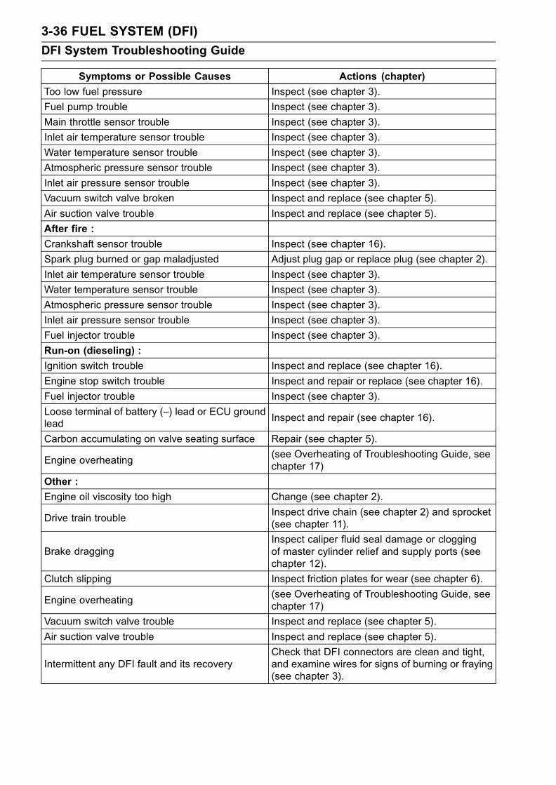
3-36 FUEL SYSTEM (DFI)
DFI System Troubleshooting Guide
Symptoms or Possible Causes Actions (chapter)
Too low fuel pressure Inspect (see chapter 3).
Fuel pump trouble Inspect (see chapter 3).
Main throttle sensor trouble Inspect (see chapter 3).
Inlet air temperature sensor trouble Inspect (see chapter 3).
Water temperature sensor trouble Inspect (see chapter 3).
Atmospheric pressure sensor trouble Inspect (see chapter 3).
Inlet air pressure sensor trouble Inspect (see chapter 3).
Vacuum switch valve broken Inspect and replace (see chapter 5).
Air suction valve trouble Inspect and replace (see chapter 5).
After fire :
Crankshaft sensor trouble Inspect (see chapter 16).
Spark plug burned or gap maladjusted Adjust plug gap or replace plug (see chapter 2).
Inlet air temperature sensor trouble Inspect (see chapter 3).
Water temperature sensor trouble Inspect (see chapter 3).
Atmospheric pressure sensor trouble Inspect (see chapter 3).
Inlet air pressure sensor trouble Inspect (see chapter 3).
Fuel injector trouble Inspect (see chapter 3).
Run-on (dieseling) :
Ignition switch trouble Inspect and replace (see chapter 16).
Engine stop switch trouble Inspect and repair or replace (see chapter 16).
Fuel injector trouble Inspect (see chapter 3).
Loose terminal of battery (–) lead or ECU groundlead
Inspect and repair (see chapter 16).
Carbon accumulating on valve seating surface Repair (see chapter 5).
Engine overheating(see Overheating of Troubleshooting Guide, seechapter 17)
Other :
Engine oil viscosity too high Change (see chapter 2).
Drive train troubleInspect drive chain (see chapter 2) and sprocket(see chapter 11).
Brake draggingInspect caliper fluid seal damage or cloggingof master cylinder relief and supply ports (seechapter 12).
Clutch slipping Inspect friction plates for wear (see chapter 6).
Engine overheating(see Overheating of Troubleshooting Guide, seechapter 17)
Vacuum switch valve trouble Inspect and replace (see chapter 5).
Air suction valve trouble Inspect and replace (see chapter 5).
Intermittent any DFI fault and its recoveryCheck that DFI connectors are clean and tight,and examine wires for signs of burning or fraying(see chapter 3).
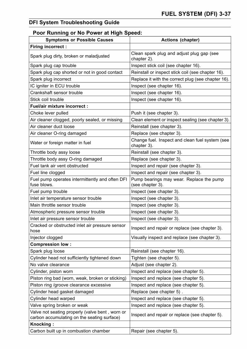
FUEL SYSTEM (DFI) 3-37
DFI System Troubleshooting Guide
Poor Running or No Power at High Speed:Symptoms or Possible Causes Actions (chapter)
Firing incorrect :
Spark plug dirty, broken or maladjustedClean spark plug and adjust plug gap (seechapter 2).
Spark plug cap trouble Inspect stick coil (see chapter 16).
Spark plug cap shorted or not in good contact Reinstall or inspect stick coil (see chapter 16).
Spark plug incorrect Replace it with the correct plug (see chapter 16).
IC igniter in ECU trouble Inspect (see chapter 16).
Crankshaft sensor trouble Inspect (see chapter 16).
Stick coil trouble Inspect (see chapter 16).
Fuel/air mixture incorrect :
Choke lever pulled Push it (see chapter 3).
Air cleaner clogged, poorly sealed, or missing Clean element or inspect sealing (see chapter 3).
Air cleaner duct loose Reinstall (see chapter 3).
Air cleaner O-ring damaged Replace (see chapter 3).
Water or foreign matter in fuelChange fuel. Inspect and clean fuel system (seechapter 3).
Throttle body assy loose Reinstall (see chapter 3).
Throttle body assy O-ring damaged Replace (see chapter 3).
Fuel tank air vent obstructed Inspect and repair (see chapter 3).
Fuel line clogged Inspect and repair (see chapter 3).
Fuel pump operates intermittently and often DFIfuse blows.
Pump bearings may wear. Replace the pump(see chapter 3).
Fuel pump trouble Inspect (see chapter 3).
Inlet air temperature sensor trouble Inspect (see chapter 3).
Main throttle sensor trouble Inspect (see chapter 3).
Atmospheric pressure sensor trouble Inspect (see chapter 3).
Inlet air pressure sensor trouble Inspect (see chapter 3).
Cracked or obstructed inlet air pressure sensorhose
Inspect and repair or replace (see chapter 3).
Injector clogged Visually inspect and replace (see chapter 3).
Compression low :
Spark plug loose Reinstall (see chapter 16).
Cylinder head not sufficiently tightened down Tighten (see chapter 5).
No valve clearance Adjust (see chapter 2).
Cylinder, piston worn Inspect and replace (see chapter 5).
Piston ring bad (worn, weak, broken or sticking) Inspect and replace (see chapter 5).
Piston ring /groove clearance excessive Inspect and replace (see chapter 5).
Cylinder head gasket damaged Replace (see chapter 5) .
Cylinder head warped Inspect and replace (see chapter 5).
Valve spring broken or weak Inspect and replace (see chapter 5).
Valve not seating properly (valve bent , worn orcarbon accumulating on the seating surface)
Inspect and repair or replace (see chapter 5).
Knocking :
Carbon built up in combustion chamber Repair (see chapter 5).

3-38 FUEL SYSTEM (DFI)
DFI System Troubleshooting Guide
Symptoms or Possible Causes Actions (chapter)
Fuel poor quality or incorrect (Use the gasolinerecommended in the Owner’s Manual)
Change fuel (see chapter 3).
Spark plug incorrect Replace it with the correct plug (see chapter 16).
Stick coil trouble Inspect (see chapter 16).
IC igniter in ECU trouble Inspect (see chapter 16).
Inlet air temperature sensor trouble Inspect (see chapter 3).
Atmospheric pressure sensor trouble Inspect (see chapter 3).
Miscellaneous :
Subthrottle sensor trouble Inspect (see chapter 3).
Subthrottle valve actuator trouble Inspect (see chapter 3).
Speed sensor trouble Inspect (see chapter 3).
Throttle valves won’t fully openInspect throttle cable and lever linkage (seechapter 3).
Brake draggingInspect caliper fluid seal damage or cloggingof master cylinder relief and supply ports (seechapter 12).
Clutch slipping Inspect friction plates for wear (see chapter 6).
Engine overheating - Water temperature sensor,crankshaft sensor or speed sensor trouble
(see Overheating of Troubleshooting Guide inchapter 17).
Engine oil level too high Repair (see chapter 7).
Engine oil viscosity too high Change (see chapter 3).
Drive train troubleInspect drive chain (see chapter 2) and sprockets(see chapter 11).
Camshaft cam worn Inspect and replace (see chapter 5).
Vacuum switch valve trouble Inspect and replace (see chapter 5).
Air suction valve trouble Inspect and replace (see chapter 5).
Catalytic converters melt down due to muffleroverheating (KLEEN)
Replace muffler (see chapter 5).
Exhaust Smokes Excessively :
(White smokes)
Piston oil ring worn Inspect and replace (see chapter 5).
Cylinder worn Inspect and replace (see chapter 5).
Valve oil seal damaged Replace (see chapter 5).
Valve guide worn Replace the guide (see chapter 5).
Engine oil level too high Repair (see chapter 7).
(Black smoke)
Air cleaner clogged Clean (see chapter 3).
Choke lever pulled Push it (see chapter 3).
Too high fuel pressure Inspect (see chapter 3) .
Injector stuck open Inspect (see chapter 3).
Water temperature sensor trouble Inspect and replace (see chapter 3).
Inlet air temperature sensor trouble Inspect and replace (see chapter 3).
(Brown smoke)
Air cleaner duct loose Reinstall (see chapter 3).
Air cleaner O-ring damaged Replace (see chapter 3).

FUEL SYSTEM (DFI) 3-39
DFI System Troubleshooting Guide
Symptoms or Possible Causes Actions (chapter)
Too low fuel pressure Inspect fuel line and fuel pump (see chapter 3).
Water temperature sensor trouble Inspect and replace (see chapter 3).
Inlet air temperature sensor trouble Inspect and replace (see chapter 3)
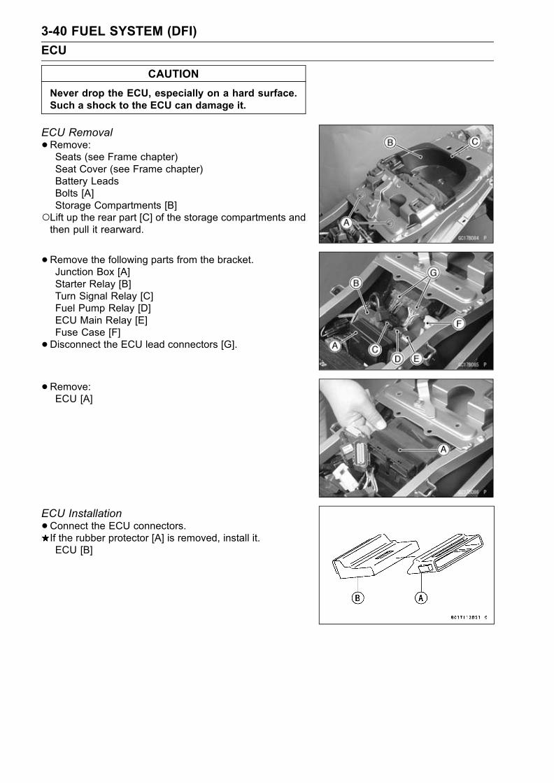
3-40 FUEL SYSTEM (DFI)
ECU
CAUTION
Never drop the ECU, especially on a hard surface.Such a shock to the ECU can damage it.
ECU Removal
•Remove:Seats (see Frame chapter)Seat Cover (see Frame chapter)Battery LeadsBolts [A]Storage Compartments [B]
Lift up the rear part [C] of the storage compartments andthen pull it rearward.
•Remove the following parts from the bracket.Junction Box [A]Starter Relay [B]Turn Signal Relay [C]Fuel Pump Relay [D]ECU Main Relay [E]Fuse Case [F]
•Disconnect the ECU lead connectors [G].
•Remove:ECU [A]
ECU Installation
•Connect the ECU connectors.If the rubber protector [A] is removed, install it.ECU [B]

FUEL SYSTEM (DFI) 3-41
ECU
• Insert the projections [A] of the rear fender front into theslits [B] of the rubber protector.
ECU Power Supply Inspection
•Visually inspect the terminals [A] of the ECU connectors.If the connector is clogged with mud or dust, blow it offwith compressed air.Replace the main harness if the terminals of the mainharness connectors are cracked, bent, or otherwise dam-aged.Replace the ECU if the terminals of the ECU connectorsare cracked, bent, or otherwise damaged.
•With the ECU connectors [A] connected, check the follow-ing ground lead for continuity with the ignition SW OFF,using a tester and needle adapter set.
ECU Grounding Inspection26, 50, or 51 (BK/Y)Terminal
←→ Battery (–) Terminal: 0 Ω
Engine Ground ←→ Battery (–) Terminal: 0 ΩIf no continuity, check the connector, the engine groundlead, or main harness, and repair or replace them if nec-essary.[B] Battery[C] Tester
Special Tool - Needle Adapter Set: 57001–1457

3-42 FUEL SYSTEM (DFI)
ECU
•Check the ECU power source voltage with a tester [A].Position the terminal in accordance with terminal numbersof ECU connectors [B] in this chapter figure.Battery [C]
ECU Power Source InspectionTester
Connections:between 13 (W/Y) Terminal andBattery (–) Terminal
between 43 (W) Terminal andBattery (–) Terminal
Ignition SW OFF: 13 (W/Y) Terminal 0 V,
43 (W) Terminal 12.5 V or more
Ignition SW ON: Battery Voltage (12.5 V or more)
If the tester does not read as specified, check the follow-ing:Power Source Wiring (see wiring diagram below)Main Fuse 30 A (see Electrical System chapter)ECU Fuse 15 A (see DFI Power Source section)ECU Main Relay (see DFI Power Source section)
ECU Power Source Circuit
1. ECU 5. Main Fuse 30 A2. Ignition Switch 6. Starter Relay3. ECU Main Relay 7. Battery4. ECU Fuse 15 A

FUEL SYSTEM (DFI) 3-43
DFI Power Source
ECU Fuse Removal
•Refer to the Electrical System chapter for the ECU fuseremoval.
ECU Fuse InstallationIf a fuse fails during operation, inspect the DFI system todetermine the cause, and then replace it with a new fuseof proper amperage.
•Refer to the Electrical System chapter for the ECU fuseinstallation.
ECU Fuse Inspection
•Refer to the Electrical System chapter for the ECU FuseInspection.
ECU Main Relay Removal
CAUTION
Never drop the relay, especially on a hard surface.Such a shock to the relay can damage it.
•Remove:Seats (see Frame chapter)
•Remove the ECU main relay [A] from the bracket anddisconnect the connector.
ECU Main Relay Inspection
•Remove the ECU main relay (see above).•Connect the hand tester [A] and one 12 V battery [B] tothe relay connector [C] as shown.
Special Tool - Hand Tester: 57001–1394
Relay Coil Terminals [1] and [2]Relay Switch Terminals [3] and [4]
Testing RelayTester range: 1 Ω rangeCriteria: When battery is connected→ 0 Ω
When battery is disconnected→ ∞ ΩIf the relay does not work as specified, replace the relay.

3-44 FUEL SYSTEM (DFI)
FI Indicator LED Light
Inspection Flow Chart

FUEL SYSTEM (DFI) 3-45
FI Indicator LED Light
LED Light Inspection
•Remove the meter unit (see Electrical System chapter).• Using two auxiliary leads, supply battery power to the FIindicator LED light [A].12 V Battery [B]
FI Indicator LED Light CheckConnector: Meter Connector [C] (disconnected)
Connection: BR/W Lead Terminal [1] of the Meter
→ Battery (+) Terminal
BR/R Lead Terminal [6] of the Meter
→ Battery (–) Terminal
Criterion: The LED light should light.
If the LED light does not go on, replace the meter unit.
1. ECU 5. Ignition Fuse 10 A2. Ignition Switch 6. Starter Relay3. FI Indicator LED Light 7. Main Fuse 30 A4. Junction Box 8. Battery

3-46 FUEL SYSTEM (DFI)
Fuel Line
Fuel Pressure Inspection
NOTEBe sure the battery is fully charged.•Remove:Seats (see Frame chapter)Fuel Tank Bolts (see Fuel Tank Removal)
• Be sure to place a piece of cloth around the fuel supplypipe of the throttle body assembly and fuel pump.
•Remove the fuel hose.WARNING
Be prepared for fuel spillage; any spilled fuel mustbe completely wiped up immediately.When the fuel hose is disconnected, fuel spills outfrom the hose and the pipe because of residualpressure. Cover the hose connection with a pieceof clean cloth to prevent fuel spillage.
• Install the fuel pressure gauge adapter [A] between thefuel supply pipes of the fuel pump and throttle body assy.
•Connect the pressure gauge [B] to the fuel pressuregauge adapter.
Special Tools - Fuel Pressure Gauge Adapter: 57001–1417Oil Pressure Gauge: 57001–125
WARNINGDo not try to start the engine with the fuel hosesdisconnected.
•Turn the ignition switch ON. The fuel pump will turn for 3seconds, and then stop.
CAUTION
Do not drive the fuel pump 3 seconds or more with-out the fuel in the fuel tank. If the fuel pump is drivenwithout the fuel, it may be damaged.
•Measure the fuel pressure with the engine stopped.Fuel Pressureright after Ignition SW ON, with pump running:
Standard: 304 kPa (3.1 kgf/cm², 44 psi)
after 3 seconds from Ignition SW ON, with pumpstopped:
Standard: 280 kPa (2.9 kgf/cm², 41 psi) , residualfuel pressure)
The system should hold the residualpressure about 30 seconds.
•Start the engine, and let it idle.•Measure the fuel pressure with the engine idling.

FUEL SYSTEM (DFI) 3-47
Fuel Line
Fuel Pressure (idling)Standard: 304 kPa (3.1 kgf/cm², 44 psi)
NOTEThe gauge hand will fluctuate. Read the pressure at theaverage of the maximum and minimum indications.
If the fuel pressure is much higher than the specified, re-place the fuel pump.If the fuel pressure is much lower than specified, checkthe following:Fuel Line LeakageAmount of Fuel Flow (see Fuel Flow Rate Inspection)If the fuel pressure is much lower than specified, and ifinspection above checks out good, replace the throttlebody assy, or the fuel pump and measure the fuel pres-sure again.
•Remove the fuel pressure gauge and adapter.• Install the fuel tank (see Fuel Tank Installation).Fuel Flow Rate Inspection
NOTEBe sure the battery is fully charged.
WARNINGGasoline is extremely flammable and can be explo-sive under certain conditions. Make sure the areais well-ventilated and free from any source of flameor sparks; this includes any appliance with a pilotlight. Do not smoke. Turn the ignition switch OFF.Be prepared for fuel spillage; any spilled fuel mustbe completely wiped up immediately.
•Turn the ignition switch, and engine stop switch OFF.•Wait until the engine cools down.• Prepare a fuel hose of the inside diameter 7.5 mm (0.30in.) and a measuring cylinder.
•Remove:Seats (see Frame chapter)Fuel Tank Bolts (see Fuel Tank Removal)
•Open the fuel tank cap [A] to lower the pressure in thetank.
• Be sure to place a piece of cloth around the fuel supplypipe of the fuel pump.
•Remove the fuel hose from the fuel pump (see Fuel PumpRemoval).
WARNINGBe prepared for fuel spillage; any spilled fuel mustbe completely wiped up immediately.When the fuel hose is disconnected, fuel spills outfrom the hose and the pipe because of residualpressure. Cover the hose connection with a pieceof clean cloth to prevent fuel spillage.

3-48 FUEL SYSTEM (DFI)
Fuel Line
•Connect the prepared fuel hose [A] to the fuel supply pipeof the fuel pump.
• Secure the fuel hose with a clamp.• Insert the fuel hose into the measuring cylinder [B].
WARNINGWipe off spilled out fuel immediately.Be sure to hold the measuring cylinder vertical.
•Close the fuel tank cap.•With the engine stopped, turn the ignition switch ON. Thefuel pump should operate for 3 seconds, and then shouldstop.
CAUTION
Do not drive the fuel pump 3 seconds or more with-out the fuel in the fuel tank. If the fuel pump is drivenwithout the fuel, it may be damaged.
•Measure the discharge for 3 seconds.Repeat this operation several times.Amount of Fuel FlowStandard: 67 mL (2.27 US oz) or more for 3 seconds
If the fuel flow is much less than the specified, check thefollowing:Battery Condition (see Electrical System chapter)
• After inspection, connect the fuel hoses. (see Fuel TankInstallation).
• Start the engine and check for fuel leakage.

FUEL SYSTEM (DFI) 3-49
Fuel Pump
Fuel Pump Removal
CAUTION
Never drop the fuel pump, especially on a hard sur-face. Such a shock to the pump can damage it.
WARNINGGasoline is extremely flammable and can be explo-sive under certain conditions. Make sure the areais well-ventilated and free from any source of flameor sparks; this includes any appliance with a pilotlight. Do not smoke. Turn the ignition switch OFF.Disconnect the battery (–) terminal.To make fuel spillage minimum, draw the fuel outfrom the fuel tank when the engine is cold. Beprepared for fuel spillage; any spilled fuel must becompletely wiped up immediately.
•Draw the fuel out from the fuel tank with a commerciallyavailable electric pump.
•Remove the fuel tank (see Fuel Tank Removal).Be careful of fuel spillage from the fuel tank since fuel stillremains in the fuel tank and fuel pump. Plug the fuel pipeof the fuel tank.
• Turn the fuel tank upside down.•Unscrew the fuel pump bolts [A], and take out the fuelpump assembly [B] and gasket.
•Discard the fuel pump gasket.CAUTION
Do not pull the leads (C) of the fuel pump and fuelreserve switch. If they are pulled, the lead terminalsmay be damaged.
Fuel Pump Installation
•Remove dirt or dust from the fuel pump [A] by lightly ap-plying compressed air.
• Replace the fuel pump gasket with a new one.

3-50 FUEL SYSTEM (DFI)
Fuel Pump
•Check that the fuel pump terminal [A] and band [B] are inplace.[C] Front
• Apply a non-permanent locking agent to the threads ofthe fuel pump bolts.
• Tighten the fuel pump bolts to a snug fit following the tight-ening sequence shown.
• Following the tightening sequence, tighten the pump boltsto the specified torque.
Torque - Fuel Pump Bolts: 9.8 N·m (1.0 kgf·m, 87 in·lb)
•Tighten the pump bolts again to check the tightness in theorder shown.
Operation Inspection
NOTEBe sure the battery is fully charged.•Turn the ignition switch ON and make sure that the fuelpump operates (make light sounds) for 3 seconds, andthen stops.
• Turn the ignition switch OFF.If the pump does not work as described above, inspectthe operating voltage.
Operating Voltage Inspection
NOTEBe sure the battery is fully charged.•Turn the ignition switch OFF.•Remove the fuel tank bolts and lift up the fuel tank.•Connect the hand tester (25 V DC) to the connector [A],with needle adapter set.
Special Tools - Hand Tester: 57001-1394Needle Adapter Set: 57001–1457
Measure the operating voltage with the engine stopped,and with the connector joined.
• Turn the ignition switch ON.The tester needle should indicate battery voltage for 3seconds, and then 0 V.
Pump Operating Voltage at PumpConnections to Pump Connectors
Tester (+) → Y/R Lead
Tester (–) → BK/W Lead
Operating Voltage at Pump Connector
Standard:Battery Voltage (12.5 V or more) for 3seconds, and then 0 V.
If the reading stays on battery voltage, and never shows0 V. Check the ECU and fuel pump relay.If the voltage is in specification, but the pump doesn’twork, replace the pump.If there is still no battery voltage, check the pump relay(see this chapter).

FUEL SYSTEM (DFI) 3-51
Fuel Pump
1. ECU 7. Starter Relay2. Ignition Switch 8. Battery3. ECU Main Relay 9. Fuel Pump4. Fuel Pump Relay 10. Engine Stop Switch5. ECU Fuse 15 A 11. Junction Box6. Main Fuse 30 A 12. Ignition Fuse 10 A

3-52 FUEL SYSTEM (DFI)
Fuel Pump Relay
Fuel Pump Relay Removal
CAUTION
Never drop the relay, especially on a hard surface.Such a shock to the relay can damage it.
•Remove:Seats (see Frame chapter)
•Remove the fuel pump relay [A] from the bracket and dis-connect the connector.
Fuel Pump Relay Inspection
•Remove the fuel pump relay (see above).•Connect the hand tester [A] and one 12 V battery [B] tothe relay connector [C] as shown.
Special Tool - Hand Tester: 57001–1394
Relay Coil Terminals [1] and [2]Relay Switch Terminals [3] and [4]
Testing RelayTester range: 1 Ω range
Criteria: When battery is connected→ 0 ΩWhen battery is disconnected→ ∞ Ω
If the relay does not work as specified, replace the relay.

FUEL SYSTEM (DFI) 3-53
Fuel Pump Relay
1. ECU2. Fuel Pump3. Ignition Switch4. ECU Main Relay5. Fuel Pump Relay6. ECU Fuse 15 A
7. Main Fuse 30 A8. Starter Relay9. Battery10. Engine Stop Switch11. Ignition Fuse 10 A12. Junction Box

3-54 FUEL SYSTEM (DFI)
Fuel Injectors
CAUTION
Never drop the injector, especially on a hard sur-face. Such a shock to the injector can damage it.
Audible Inspection
•Start the engine.• Apply the tip of a screwdriver [A] to the injector [B]. Putthe grip end onto your ear, and listen whether the injectoris clicking or not.
• A sound scope can also be used.•Do the same for the other injector.If all the injectors click at a regular intervals, the injectorsare good.The click interval becomes shorter as the engine speedrises.If either injector doesn’t click, perform the “Injector SignalTest” for injector operation.
Injector Signal Test
•Prepare two test light sets with male terminals as shown.Rating of Bulb [A]: 12 V × 3 ∼ 3.4 WTerminal Width [B]: 1.8 mm (0.07 in)Terminal Thickness [C]: 0.8 mm (0.03 in)
CAUTION
Do not use larger terminals than specified above. Alarger terminal could damage the injector main har-ness connector (female), leading to harness repairor replacement.Be sure to connect bulbs in series. The bulb worksas a current limiter to protect the solenoid in theinjector from excessive current.
•Remove connectors for injector [A].• Connect each test light set [B] to the injector sub harnessconnector [C].
• Turn the ignition switch ON.•While cranking the engine with the starter motor, watchthe test lights.If the test lights flicker at regular intervals, the injectorcircuit in the ECU, and the wiring are good. Perform the“Injector Resistance Inspection”.
Injector signals can be also confirmed by connecting thehand tester (× 10 V AC) instead of the test light set tothe injector main harness (female) connector. Crank theengine with the starter motor, and check to see if the handoscillates at regular intervals.
Special Tool - Hand Tester: 57001-1394
If the test light doesn’t flicker (or the test hand doesn’toscillates), check the wiring and connectors again. If thewiring is good, check the injector voltage.
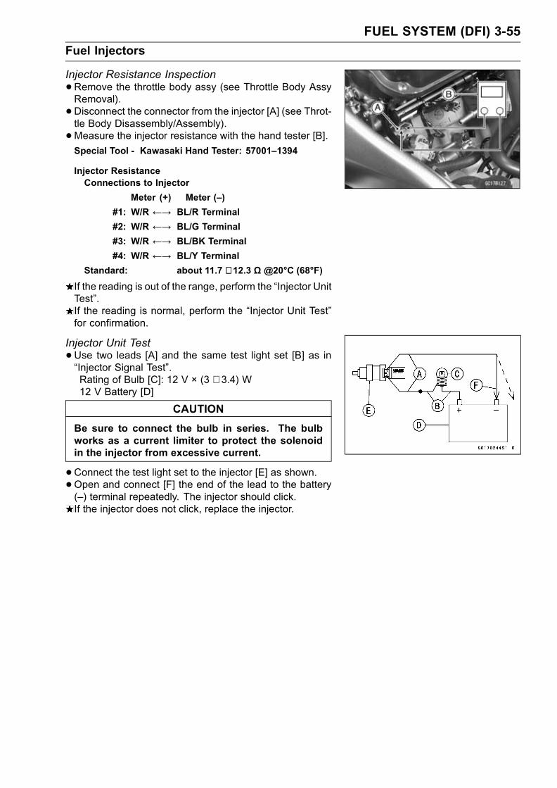
FUEL SYSTEM (DFI) 3-55
Fuel Injectors
Injector Resistance Inspection
•Remove the throttle body assy (see Throttle Body AssyRemoval).
• Disconnect the connector from the injector [A] (see Throt-tle Body Disassembly/Assembly).
•Measure the injector resistance with the hand tester [B].Special Tool - Kawasaki Hand Tester: 57001–1394
Injector ResistanceConnections to Injector
Meter (+) Meter (–)
#1: W/R ←→ BL/R Terminal
#2: W/R ←→ BL/G Terminal
#3: W/R ←→ BL/BK Terminal
#4: W/R ←→ BL/Y Terminal
Standard: about 11.7 ∼ 12.3 Ω @20°C (68°F)
If the reading is out of the range, perform the “Injector UnitTest”.If the reading is normal, perform the “Injector Unit Test”for confirmation.
Injector Unit Test
•Use two leads [A] and the same test light set [B] as in“Injector Signal Test”.Rating of Bulb [C]: 12 V × (3 ∼ 3.4) W12 V Battery [D]
CAUTION
Be sure to connect the bulb in series. The bulbworks as a current limiter to protect the solenoidin the injector from excessive current.
•Connect the test light set to the injector [E] as shown.•Open and connect [F] the end of the lead to the battery(–) terminal repeatedly. The injector should click.If the injector does not click, replace the injector.

3-56 FUEL SYSTEM (DFI)
Fuel Injectors
Injector Voltage Inspection
•Turn the ignition switch OFF.•Remove:Fuel Tank (see Fuel Tank Removal)
•Connect a digital voltmeter [A] to the connector [B], withthe needle adapter set.
Special Tool - Needle Adapter Set: 57001-1457
Injector Power Source VoltageConnector to Injector #1, #2, #3, #4
Meter (+) → W/R lead
Meter (–) → Battery (–) Terminal
• Install the fuel tank.• Turn the ignition switch ON.Power Source Voltage at Injector ConnectorStandard: Battery Voltage (12.5 V or more)
If the power source voltage is less than standard, checkthe wiring (see wiring diagram in this section), fuel pumprelay (Fuel Pump Relay Inspection) and ECU powersource (see ECU Power Supply Inspection).
• Turn the ignition switch OFF.•Remove:Fuel Tank (see Fuel Tank Removal)
•Connect a digital voltmeter [A] to the connector [B], withthe needle adapter set [C].
Special Tool - Needle Adapter Set: 57001-1457
Injector Output VoltageConnections to Injector #1
Meter (+) → BL/R lead
Meter (–) → Battery (-) Terminal
Connections to Injector #2
Meter (+) → BL/G lead
Meter (–) → Battery (-) Terminal
Connections to Injector #3
Meter (+) → BL/BK lead
Meter (–) → Battery (-) Terminal
Connections to Injector #4
Meter (+) → BL/Y lead
Meter (–) → Battery (-) Terminal
• Install the fuel tank.• Turn the ignition switch ON.Output Voltage at Injector ConnectorStandard: Battery Voltage (12.5 V or more)
If the output voltage is out of the standard, replace theECU.

FUEL SYSTEM (DFI) 3-57
Fuel Injectors
Injector Fuel Line Inspection
•Remove the throttle body assy (see this chapter).• Check the injector fuel line for leakage as follows:Connect a commercially available vacuum/pressurepump [A] to the nipple of the delivery pipe [B] with thefuel hose [C] (both ends connected with the clamps [D])as shown.
Torque - Fuel Hose Clamp Screws: 1.5 N·m (0.15 kgf·m, 13in·lb)
Apply soap and water solution to the areas [E] as shown.Watching the pressure gauge, squeeze the pump lever[F], and build up the pressure until the pressure reachesthe maximum pressure.
Fuel Line Maximum PressureStandard: 300 kPa (3.06 kgf/cm², 43 psi)
CAUTION
During pressure testing, do not exceed the maxi-mum pressure for which the system is designed.
•Watch the gauge for at least 6 seconds.If the pressure holds steady, the system is good.If the pressure drops at once, or if bubbles are found inthe area, the line is leaking. Replace the delivery pipe,injectors and related parts.Repeat the leak test, and check the fuel line for no leak-age.
• Install the throttle body assy (see this chapter).• Run the hoses correctly (see Cable, Wire, and Hose Rout-ing section in Appendix chapter).

3-58 FUEL SYSTEM (DFI)
Fuel Injectors
1. ECU2. Fuel Injector #43. Fuel Injector #34. Fuel Injector #25. Fuel Injector #16. Ignition Switch7. ECU Main Relay8. Fuel Pump Relay
9. ECU Fuse 15 A10. Main Fuse 30 A11. Starter Relay12. Battery13. Engine Stop Switch14. Ignition Fuse 10 A15. Junction Box

FUEL SYSTEM (DFI) 3-59
Self-Diagnosis
Self-diagnosis OutlineThe self-diagnosis system has three modes and can be
switched to another mode by grounding the self-diagnosisterminal [A].
User Mode:The ECU notifies the rider of troubles in DFI system and
ignition system by lighting the FI indicator when DFI systemand ignition system parts are faulty, and initiates fail-safefunction. In case of serious troubles ECU stops the injec-tion/ignition/starter motor operation.Dealer Mode 1:The FI indicator LED light emits service code(s) to show
the problem(s) which the DFI system and ignition systemhas at the moment of diagnosis.Dealer Mode 2:The FI indicator light LED emits service code(s) to show
the problem(s) which the DFI system and ignition systemhad in the past.
Self-diagnosis ProceduresWhen a problem occurs with the DFI system and ignitionsystem, the DFI indicator LED light [A] goes on.
NOTEUse a fully charged battery when conductingself-diagnosis. Otherwise, the LED light blinks veryslowly or doesn’t blink.Keep the self-diagnosis terminal grounded during self-diagnosis, with a auxiliary lead.
•Remove the seats (see Frame chapter) and pull the self-diagnosis terminal [G].
• Turn on the ignition switch.•Connect an auxiliary a lead [E] for grounding to the self-diagnosis terminal.
• To enter the self-diagnosis dealer mode 1 ground [A] theself-diagnosis indicator terminal to the ground for morethan 2 seconds [C], and then keep it grounded continu-ously [D].Count the blinks of the LED light to read the service code.Keep the auxiliary lead ground until you finish reading theservice code.
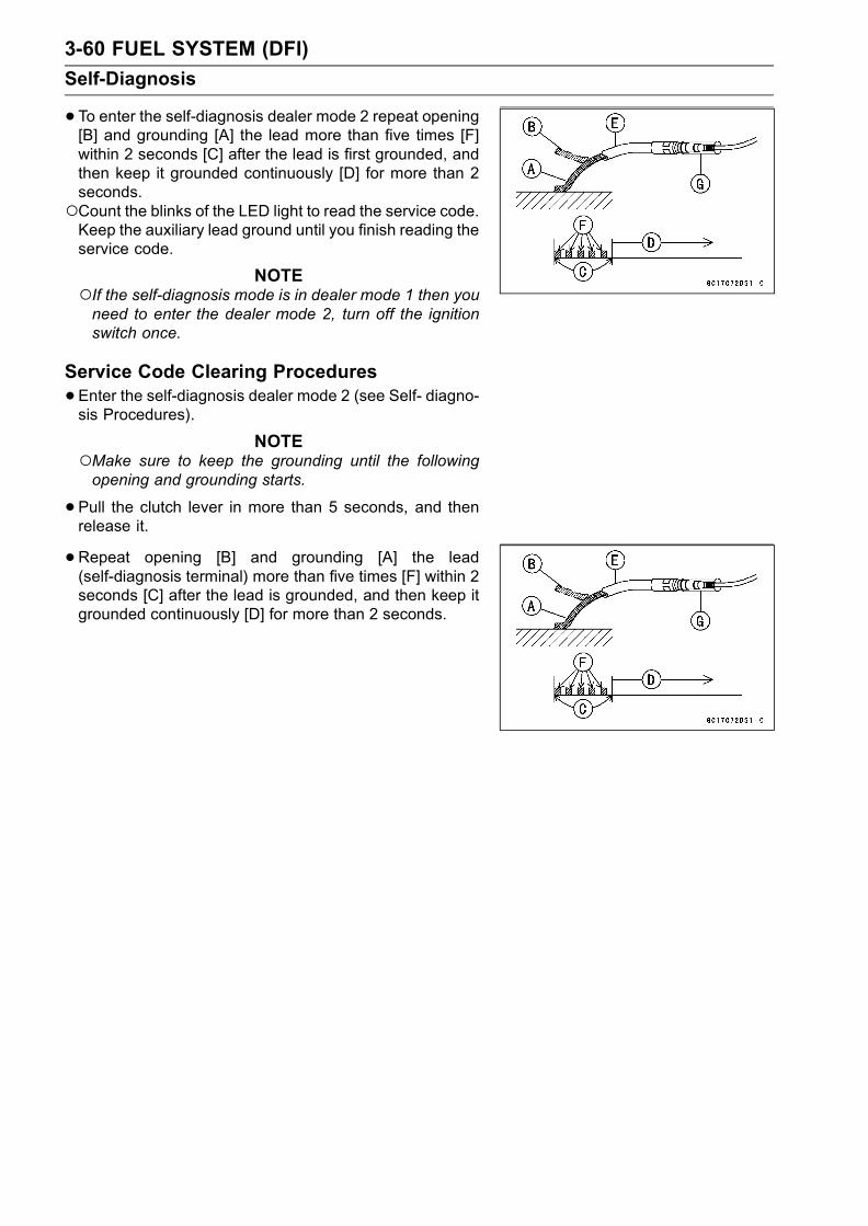
3-60 FUEL SYSTEM (DFI)
Self-Diagnosis
•To enter the self-diagnosis dealer mode 2 repeat opening[B] and grounding [A] the lead more than five times [F]within 2 seconds [C] after the lead is first grounded, andthen keep it grounded continuously [D] for more than 2seconds.Count the blinks of the LED light to read the service code.Keep the auxiliary lead ground until you finish reading theservice code.
NOTEIf the self-diagnosis mode is in dealer mode 1 then youneed to enter the dealer mode 2, turn off the ignitionswitch once.
Service Code Clearing Procedures
•Enter the self-diagnosis dealer mode 2 (see Self- diagno-sis Procedures).
NOTEMake sure to keep the grounding until the followingopening and grounding starts.
•Pull the clutch lever in more than 5 seconds, and thenrelease it.
• Repeat opening [B] and grounding [A] the lead(self-diagnosis terminal) more than five times [F] within 2seconds [C] after the lead is grounded, and then keep itgrounded continuously [D] for more than 2 seconds.

FUEL SYSTEM (DFI) 3-61
Self-Diagnosis

3-62 FUEL SYSTEM (DFI)
Self-Diagnosis
How to Read Service CodesService codes are shown by a series of long or short blinks of the FI indicator LED light as shownbelow.Read 10th digit and unit digit as the FI indicator LED light blinks.When there are a number of problems, all the service codes can be stored and the display willbegin starting from the lowest number service code in the numerical order. Then after completingall codes, the display is repeated until the self-diagnosis indicator terminal is open.If there is no problem, no code and unlight.For example, if two problems occurred in the order of 21, 12, the service codes are displayed fromthe lowest number in the order listed.(12 → 21) → (12 → 21) → · · · (repeated)
If the problem is with the following parts, the ECU cannot memorize these problems, the FI indicatorLED light doesn’t go on, and no service codes can be displayed.FI Indicator LED LightFuel PumpFuel Pump RelayDFI Main RelayECU Power Source Wiring and Ground Wiring (see ECU Inspection in this chapter)Fuel Injectors
How to Erase Service CodesEven if the ignition SW is turned OFF, the battery or the ECU are disconnected, or the problem issolved, all service codes remain in the ECU.Refer to Service Code Clearing Procedure for the service code erasure.

FUEL SYSTEM (DFI) 3-63
Self-Diagnosis
Service Code Table
ServiceCode
FI Indicator LED Light Problems (1)
11 Main throttle sensor malfunction, wiring open or short
12Inlet air pressure sensor malfunction, wiring open orshort
13Inlet air temperature sensor malfunction, wiring openor short
14Water temperature sensor malfunction, wiring openor short
15Atmospheric pressure sensor malfunction, wiringopen or short
21 Crankshaft sensor malfunction, wiring open or short
23Camshaft position sensor malfunction, wiring openor short
24 Speed sensor malfunction, wiring open or short
25 Speed sensor malfunction, wiring open or short
31Vehicle-down sensor, malfunction, wiring open orshort
32 Subthrottle sensor malfunction, wiring open or short
51Stick (Ignition) coil #1 malfunction, wiring open orshort
52Stick (Ignition) coil #2 malfunction, wiring open orshort
53Stick (Ignition) coil #3 malfunction, wiring open orshort
54Stick (Ignition) coil #4 malfunction, wiring open orshort
62Subthrottle valve actuator malfunction, wiring openor short
Footnotes:(1) The ECU may be involved in these problems. If all the parts and circuits checked out good, be
sure to check the ECU for ground and power supply. If the ground and power supply are checkedgood, replace the ECU.

3-64 FUEL SYSTEM (DFI)
Self-Diagnosis
BackupsThe ECU takes the following measures to prevent engine damage when the DFI or the ignitionsystem parts have troubles.
ServiceCodes
PartsOutput Signal UsableRange or Criteria
Backups by ECU
11
MainThrottleSensor
Main Throttle SensorOutput Voltage0.2 ∼ 4.8 V
If the main throttle sensor system fails (the signalis out of the usable range, wiring short or open),the ECU locks ignition timing into the ignitiontiming at closed throttle position and sets the DFIin the D-J method.
Also, the main throttle sensor system and inlet airpressure fails, the ECU locks ignition timing intothe ignition timing at closed throttle position andsets the DFI in the α-N method.
12Inlet AirPressureSensor
Inlet Air Pressure(absolute)Pv = 100 mmHg ∼ 900mmHg
If the inlet air pressure sensor system fails (thesignal Pv is out of the usable range, wiring shortor open), the ECU sets the DFI in the α - Nmethod (1).
13Inlet AirTempera-ture Sensor
Inlet Air TemperatureTa = – 47°C ∼ + 178°C
If the inlet air temperature sensor fails (the signalis out of the usable range, wiring short or open),the ECU sets Ta at 40°C.
14Water Tem-peratureSensor
Water TemperatureTw = – 30C° ∼ + 120°C
If the water temperature sensor system fails (thesignal is out of the usable range, wiring short orop en), the ECU sets Tw at 80°C.
15
Atmo-sphericPressureSensor
Absolute AtmosphericPressurePa = 100 mmHg ∼ 900mmHg
If the atmospheric pressure sensor system fails(the signal is out of the usable range, wiring shortor open), the ECU sets Pa at 760 mmHg (thestandard atmospheric pressure).
21CrankshaftSensor
Crankshaft sensor mustsend 23 signals (outputsignal) to the ECU at theone cranking.
If crankshaft sensor generates less than 23 ormore signals, the engine stops by itself.
23CamshaftPositionSensor
Cam sensor must sendone signal (output signal)to the ECU at the twocranking
If the camshaft position sensor system fails(the signal is missing, wiring short or open), theECU continues to ignite cylinders in the samesequence following the last good signal.
24SpeedSensor
Speed sensor must send4 signals (output signal)to the ECU at the onerotation of the enginesprocket
If the speed sensor system fails (no signal, wiringshort or open), the speedometer shows 0.
25SpeedSensor
The gear position isdecided by the signal ofthe speed sensor.
If the speed sensor system fails (no signal, wiringshort or open), the ECU set the top (6) gearposition.
31Vehicle-downSensor
Vehicle-down SensorOutput Voltage (signal)Vd = 0.4 V ∼ 4.4 V
If the vehicle-down sensor system has failures(the output voltage Vd is more than usable range,wiring open), the ECU shuts off the fuel pump,the fuel injectors and the ignition system.
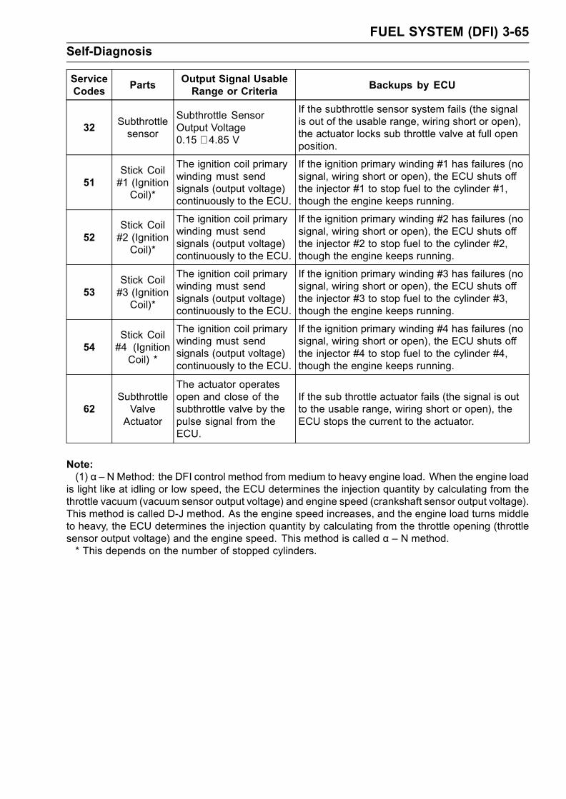
FUEL SYSTEM (DFI) 3-65
Self-Diagnosis
ServiceCodes
PartsOutput Signal UsableRange or Criteria
Backups by ECU
32Subthrottlesensor
Subthrottle SensorOutput Voltage0.15 ∼ 4.85 V
If the subthrottle sensor system fails (the signalis out of the usable range, wiring short or open),the actuator locks sub throttle valve at full openposition.
51Stick Coil#1 (IgnitionCoil)*
The ignition coil primarywinding must sendsignals (output voltage)continuously to the ECU.
If the ignition primary winding #1 has failures (nosignal, wiring short or open), the ECU shuts offthe injector #1 to stop fuel to the cylinder #1,though the engine keeps running.
52Stick Coil#2 (IgnitionCoil)*
The ignition coil primarywinding must sendsignals (output voltage)continuously to the ECU.
If the ignition primary winding #2 has failures (nosignal, wiring short or open), the ECU shuts offthe injector #2 to stop fuel to the cylinder #2,though the engine keeps running.
53Stick Coil#3 (IgnitionCoil)*
The ignition coil primarywinding must sendsignals (output voltage)continuously to the ECU.
If the ignition primary winding #3 has failures (nosignal, wiring short or open), the ECU shuts offthe injector #3 to stop fuel to the cylinder #3,though the engine keeps running.
54Stick Coil#4 (IgnitionCoil) *
The ignition coil primarywinding must sendsignals (output voltage)continuously to the ECU.
If the ignition primary winding #4 has failures (nosignal, wiring short or open), the ECU shuts offthe injector #4 to stop fuel to the cylinder #4,though the engine keeps running.
62SubthrottleValveActuator
The actuator operatesopen and close of thesubthrottle valve by thepulse signal from theECU.
If the sub throttle actuator fails (the signal is outto the usable range, wiring short or open), theECU stops the current to the actuator.
Note:(1) α – N Method: the DFI control method frommedium to heavy engine load. When the engine load
is light like at idling or low speed, the ECU determines the injection quantity by calculating from thethrottle vacuum (vacuum sensor output voltage) and engine speed (crankshaft sensor output voltage).This method is called D-J method. As the engine speed increases, and the engine load turns middleto heavy, the ECU determines the injection quantity by calculating from the throttle opening (throttlesensor output voltage) and the engine speed. This method is called α – N method.* This depends on the number of stopped cylinders.

3-66 FUEL SYSTEM (DFI)
Main Throttle Sensor (Service Code 11)
The main throttle sensor is a rotating variable resistor thatchange output voltage according to throttle operating. TheECU senses this voltage change and determines fuel injec-tion quantity, and ignition timing according to engine rpm,and throttle opening.Input Terminal [A]Output Terminal [B]Ground Terminal [C]
Main Throttle Sensor Removal/Adjustment
CAUTION
Do not remove or adjust themain throttle sensor [A]since it has been adjusted and set with precision atthe factory.Never drop the sensor, especially on a hard surface.Such a shock to the sensor can damage it.
Main Throttle Sensor Connector [B]
Input Voltage Inspection
NOTEBe sure the battery is fully charged.•Turn the ignition switch OFF.•Remove the ECU (see this chapter). Do not disconnectthe ECU connectors.
•Connect a digital voltmeter [A] to the connector [B], usingthe needle adapter set.
Special Tool - Needle Adapter Set: 57001–1457
Main Throttle Sensor Input VoltageConnections to ECU Connector
Meter (+)→ BL lead (terminal 1)
Meter (–)→ BR/BK lead (terminal 4)
•Measure the input voltage with the engine stopped, andwith the connectors joined.
• Turn the ignition switch ON.Input Voltage at ECU ConnectorStandard: 4.75 ∼ 5.25 V DC
•Turn the ignition switch OFF.If the reading of input voltage is less than the standard,check the ECU for its ground, power supply and wiringshorted.If the input voltage is within the standard range, check theinput voltage at the main throttle sensor connector.
•Remove the throttle body assembly temporarily (seeThrottle Body Assy Removal).

FUEL SYSTEM (DFI) 3-67
Main Throttle Sensor (Service Code 11)
•Disconnect the main throttle sensor connector [A] andconnect the harness adapter [B] between the harnessconnector and main throttle sensor connector.
•Connect a digital meter to the harness adapter leads.Special Tool - Throttle Sensor Harness Adapter : 57001
-1538
Main Throttle Sensor Input VoltageConnections to Sensor
Meter (+)→ BL lead
Meter (–)→ BR/BK lead
• Install the throttle body assembly.•Measure the sensor input voltage with the enginestopped, and with the connector joined.
• Turn the ignition switch ON.Input Voltage at SensorStandard: 4.75 ∼ 5.25 V DC
•Turn the ignition switch OFF.If the reading is out of the range, check the wiring (seewiring diagram in this section).If the reading is good, check the output voltage of thesensor.

3-68 FUEL SYSTEM (DFI)
Main Throttle Sensor (Service Code 11)
Output Voltage Inspection
•Measure the output voltage at the ECU in the same wayas input voltage inspection. Note the following.Digital Voltmeter [A]Connector [B]
Special Tool - Needle Adapter Set: 57001–1457
Main Throttle Sensor Output VoltageConnections to ECU
Meter (+) → Y/W lead (terminal 2)Meter (–) → BR/BK lead (terminal 14)
•Start the engine and warm it up thoroughly.
•Check idle speed to ensure throttle opening is correct.Idle SpeedStandard: 1 300 r/min (rpm)
If the idle speed is out of the specified range, adjust theidle speed (see Idle Speed Inspection in Periodic Mainte-nance chapter).
• Turn the ignition switch OFF.•Measure the output voltage with the engine stopped, andwith the connector joined.
• Turn the ignition switch ON.•Measure the output voltage when the throttle is fullyopened or completely closed.
Output Voltage at ECUStandard: 1.02 ∼ 4.62 V DC (at idle throttle
opening to full throttle opening)
NOTEThe throttle sensor is operating correctly if the followingvoltages are obtained:• 1.02 VDC (or slightly higher) with the throttle at the idleposition.• 4.62 VDC (or slightly lower) with the throttle at the fullyopen position.
CAUTION
Do not remove or adjust the main throttle sensor.It has been adjusted and set with precision at thefactory.Never drop the sensor can especially on a hard sur-face. A shock to the sensor can damage it.
If the output voltage is within the standard range, checkthe ECU for a good ground, and power supply (see thischapter). If the ground and power supply are good, re-place the ECU.If the output voltage is far out of the standard range (e.g.when the wiring is open, the reading is 0 V), check theoutput voltage again at the sensor connector.

FUEL SYSTEM (DFI) 3-69
Main Throttle Sensor (Service Code 11)
•Disconnect the main throttle sensor connector [A] andconnect the harness adapter [B] between the harnessconnector and main throttle sensor connector.
•Connect a digital meter to the harness adapter leads.Special Tool - Throttle Sensor Harness Adapter :
57001–1538
Throttle Sensor Output VoltageConnections to Sensor
Meter (+) → Y/W lead
Meter (–) → BR/BK lead
•Measure the sensor output voltage with the enginestopped, and with the connector joined.
• Turn the ignition switch ON.•Measure the output voltage when the throttle is fullyopened or completely closed.
Output Voltage at SensorStandard: 1.02 ∼ 4.62 V DC (at idle throttle
opening to full throttle opening)
NOTEThe throttle sensor is operating correctly if the followingvoltages are obtained:• 1.02 VDC (or slightly higher) with the throttle at the idleposition.• 4.62 VDC (or slightly lower) with the throttle at the fullyopen position.
CAUTION
Do not remove or adjust the main throttle sensor.It has been adjusted and set with precision at thefactory.Never drop the sensor, especially on a hard surface.A shock to the sensor can damage it.
NOTEThe standard voltage marked with an asterisk refers tothe value when the voltage reading at the Input VoltageInspection shows 5V exactly.When the input voltage reading shows other than 5V,derive a voltage range as follows.Example:In the case of a input voltage of 4.75 V.1.02 × 4.75 ÷ 5.00 = 0.97 V4.62 × 4.75 ÷ 5.00 = 4.39 VThus, the valid range is 0.97 ∼ 4.39 V
•After throttle sensor voltage inspection, remove the har-ness adapter.If the reading is out of the standard range, inspect thethrottle sensor resistance.If the output voltage is normal, check the wiring for conti-nuity (see next diagram).

3-70 FUEL SYSTEM (DFI)
Main Throttle Sensor (Service Code 11)
Resistance Inspection
•Turn the ignition switch OFF.•Disconnect the main throttle sensor connector.•Connect a digital meter [A] to the main throttle sensorconnector [B].
•Measure the main throttle sensor resistance.Main Throttle Sensor ResistanceConnections: BL lead [C]←→ BR/BK lead [D]
Standard: 4 ∼ 6 kΩIf the reading is out of the range, replace the throttle bodyassy.If the reading is within the range, but the problem stillexists, replace the ECU (see this chapter).
1. ECU2. Subthrottle Valve Actuator3. Subthrottle Sensor4. Main Throttle Sensor

FUEL SYSTEM (DFI) 3-71
Inlet Air Pressure Sensor (Service Code 12)
CAUTION
Never drop the sensor, especially on a hard surface.Such a shock to the part can damage it.
Removal
•Turn the ignition switch off.• Remove:Air Cleaner Housing (see Air Cleaner Housing Removal)Inlet Air Pressure Sensor Connector [A]Inlet Air Pressure Sensor Screw [B]Inlet Air Pressure Sensor [C]Vacuum Hose [D]
Installation
NOTEThe inlet air pressure sensor is the same part as the at-mospheric sensor except that the sensor has a vacuumhose and different wiring.
• Install:Vacuum Hose [A]Inlet Air Pressure Sensor [B]
Torque - Inlet Air Pressure Sensor Screw: 4.9 N·m (0.50kgf·m, 43 in·lb)
[C] Vacuum Hoses
Input Voltage Inspection
NOTEBe sure the battery is fully charged.The inspection is the same as “Input Voltage Inspection”of the throttle sensor and the atmospheric pressure sen-sor.
•Turn the ignition switch OFF.•Remove the ECU (see this chapter). Do not disconnectthe ECU connectors.
•Connect a digital voltmeter [A] to the connector [B], withthe needle adapter set.
Special Tool - Needle Adapter Set: 57001–1457
Inlet Air Pressure Sensor Input VoltageConnections to ECU
Meter (+)→ BL lead (terminal 1)
Meter (–)→ BR/BK lead (terminal 14)
•Measure the input voltage with the engine stopped, andwith the connectors joined.
• Turn the ignition switch ON.Input Voltage at ECUStandard: 4.75 ∼ 5.25 V DC
If the reading is less than the standard range, check theECU for its ground, and power supply (see this chapter). Ifthe ground and power supply are good, replace the ECU.

3-72 FUEL SYSTEM (DFI)
Inlet Air Pressure Sensor (Service Code 12)
If the reading is within the standard range, and check theinput voltage again at the sensor connector.Remove the air cleaner housing (see Air Cleaner HousingRemoval).
• Disconnect the inlet air pressure sensor connector andconnect the harness adapter [A] between the sub harnessconnector and inlet air pressure sensor connector.
•Connect a digital meter to the harness adapter leads.[B] Inlet Air Pressure Sensor
Special Tool - Sensor Harness Adapter: 57001–1561
Inlet Air Pressure Sensor Input VoltageConnections to Sensor
Meter (+) → BL lead [C]
Meter (–) → BR/BK lead [D]
•Measure the input voltage with the engine stopped.• Turn the ignition switch ON.Input Voltage at Sensor ConnectorStandard: 4.75 ∼ 5.25 V DC
If the reading is out of the standard range, check thewiring (see wiring diagram in this section).If the reading is good, the input voltage is normal. Checkthe output voltage.
• Turn the ignition switch OFF.Output Voltage Inspection
•Measure the output voltage at the ECU in the same wayas input voltage inspection. Note the following.
Inlet Air Pressure Sensor Output VoltageConnections to ECU
Meter (+)→ Y/BL lead (terminal 17)
Meter (–) → BR/BK lead (terminal 14)
Output Voltage at ECUUsable Range: 3.80 ∼ 4.20 V DC at the standard
atmospheric pressure (101.32 kPa,76 cmHg abs.)
NOTEThe output voltage changes according to the local at-mospheric pressure.The vacuum sensor output voltage is based on a nearlyperfect vacuum in the small chamber of the sensor. So,the sensor indicates absolute vacuum pressure.
If the output voltage is within the usable range, check theECU for its ground, and power supply (see this chapter). Ifthe ground and power supply are good, replace the ECU.

FUEL SYSTEM (DFI) 3-73
Inlet Air Pressure Sensor (Service Code 12)
If the output voltage is far out of the usable range, checkthe output voltage again at the sensor connector [A](when the lead is open, the output voltage is about 1.8V).
•Connect a digital meter to the harness adapter leads.[B] Inlet Air Pressure Sensor
Special Tool - Sensor Harness Adapter: 57001–1561
Inlet Air Pressure Sensor Output VoltageConnections to Sensor
Meter (+) → Y/BL lead [C]
Meter (–) → BR/BK lead [D]
Output Voltage at Sensor ConnectorUsable Range: 3.80 ∼ 4.20 V DC at the standard
atmospheric pressure (101.32 kPa or76 cmHg absolute)
If the output voltage is normal, check the wiring for conti-nuity (see next diagram).If the output voltage is out of the usable range, replacethe sensor.
• Turn the ignition switch OFF.•Remove the throttle sensor harness adapter.
1. ECU 2. Inlet Air Pressure Sensor
If you need to check the inlet air pressure sensor for vac-uum other than 76 cmHg (abs), check the output voltageas follows:

3-74 FUEL SYSTEM (DFI)
Inlet Air Pressure Sensor (Service Code 12)
•Remove the inlet air pressure sensor [A] and disconnectthe vacuum hose from the sensor.Do not disconnect the sensor connector.•Connect an auxiliary hose [B] to the inlet air pressure sen-sor.
• Temporarily install the inlet air pressure sensor.Connect a commercially available digital meter [C], vac-uum gauge [D], and the fork oil level gauge [E] to the inletair pressure sensor.
Special Tools - Fork Oil Level Gauge: 57001-1290Sensor Harness Adapter: 57001-1561
Inlet Air Pressure Sensor Output Voltage Connection toSensorMeter (+) → Y/BL lead
Meter (–) → BR/BK lead
Turn the ignition switch ON.Measure the inlet air pressure sensor output voltage fromvarious vacuum readings, while pulling the handle of thefork oil level gauge.Check the inlet air pressure sensor output voltage, usingthe following formula and chart.
Suppose:Pg : Vacuum Pressure (gauge) of Throttle AssyPl : Local Atmospheric Pressure (absolute) measured by
a barometerPv : Vacuum Pressure (absolute) of Throttle AssyVv : Sensor Output Voltage (v)
thenPv = Pl – Pg
For example, suppose the following data is obtained:Pg = 8 cmHg (vacuum gauge reading)Pl = 70 cmHg (barometer reading)Vv = 3.2 V (digital volt meter reading)
thenPv = 70 – 8 = 62 cmHg (abs)
Plot this Pv (62 cmHg) at a point [1] on the chart and draw avertical line through the point. Then, you can get the usablerange [2] of the sensor output voltage.Usable range = 3.08 ∼ 3.48 V
Plot Vv (3.2 V) on the vertical line. → Point [3].Results: In the chart, Vv is within the usable range andthe sensor is normal.

FUEL SYSTEM (DFI) 3-75
Inlet Air Pressure Sensor (Service Code 12)
Vv: Inlet Air Pressure Sensor Output Volt-age (V)
ID: Idling
(Digital Meter Reading) TO: Throttle Full Open
Pv: Throttle Vacuum Pressure (absolute) ST: Standard of Sensor Output Voltage (v)
Ps: Standard Atmospheric Pressure (abso-lute)
UR: Usable Range of Sensor Output Voltage (v)

3-76 FUEL SYSTEM (DFI)
Inlet Air Temperature Sensor (Service Code 13)
Removal/Installation
CAUTION
Never drop the sensor, especially on a hard surface.Such a shock to the sensor can damage it.
•Remove the fuel tank (see Fuel Tank Removal).• Disconnect the connector [A] from the inlet air tempera-ture sensor.
• Pull out the inlet air temperature sensor [B].
• Install the inlet air temperature sensor [A] in the grommet[B].
Output Voltage Inspection
NOTEBe sure the battery is fully charged.•Remove the ECU (see this chapter). Do not disconnectthe ECU connectors.
•Connect a digital voltmeter to the ECU connector, usingneedle adapter set.
Special Tool - Needle Adapter Set: 57001–1457
Inlet Air Temperature Sensor Output VoltageConnections to ECU Connector
Meter (+) → P lead (terminal 18)
Meter (–) → BR/BK lead (terminal 14)
•Measure the sensor output voltage with the enginestopped and the connector joined.
• Turn the ignition switch ON.Output Voltage at ECUStandard: about 2.25 ∼ 2.50 V at inlet air
temperature 20°C (68°F)
NOTEThe output voltage changes according to the inlet airtemperature.
•Turn the ignition switch OFF.

FUEL SYSTEM (DFI) 3-77
Inlet Air Temperature Sensor (Service Code 13)
If the output voltage is out of the specified, check the ECUfor its ground, and power supply (see ECU section in thischapter). If the ground and power supply are good, re-place the ECU.If the output voltage is far out of the specified (e.g. whenthe wiring is open, the voltage is about 4.6 V), remove thefuel tank cover, and check the wiring (see next diagram).
•Remove the needle adapter set, and apply siliconesealant to the seals of the connector for waterproofing.
Silicone Sealant (Kawasaki Bond: 56019-120)
- Seals of ECU Connectors
If the wiring is good, check the sensor resistance.
Sensor Resistance Inspection
•Remove the inlet air temperature sensor (see this sec-tion).
• Suspend the sensor [A] in a container of machine oil sothat the heat-sensitive portion is submerged.
• Suspend a thermometer [B] with the heat-sensitive por-tion [C] located in almost the same depth with the sensor.
NOTEThe sensor and thermometer must not touch the con-tainer side or bottom.
•Place the container over a source of heat and graduallyraise the temperature of the oil while stirring the oil gentlyfor even temperature.
•Using a digital meter, measure the internal resistanceof the sensor across the terminals at the temperaturesshown in the table.
Inlet Air Temperature Sensor ResistanceStandard: 1.6 ∼ 3.7 kΩ at 20°C (68°F)
0.24 ∼ 0.43 kΩ at 80°C (176°F)
If themeasurement is out of the range, replace the sensor.If the measurement is within the specified, replace theECU.

3-78 FUEL SYSTEM (DFI)
Inlet Air Temperature Sensor (Service Code 13)
1. ECU 2. Inlet Air Temperature Sensor
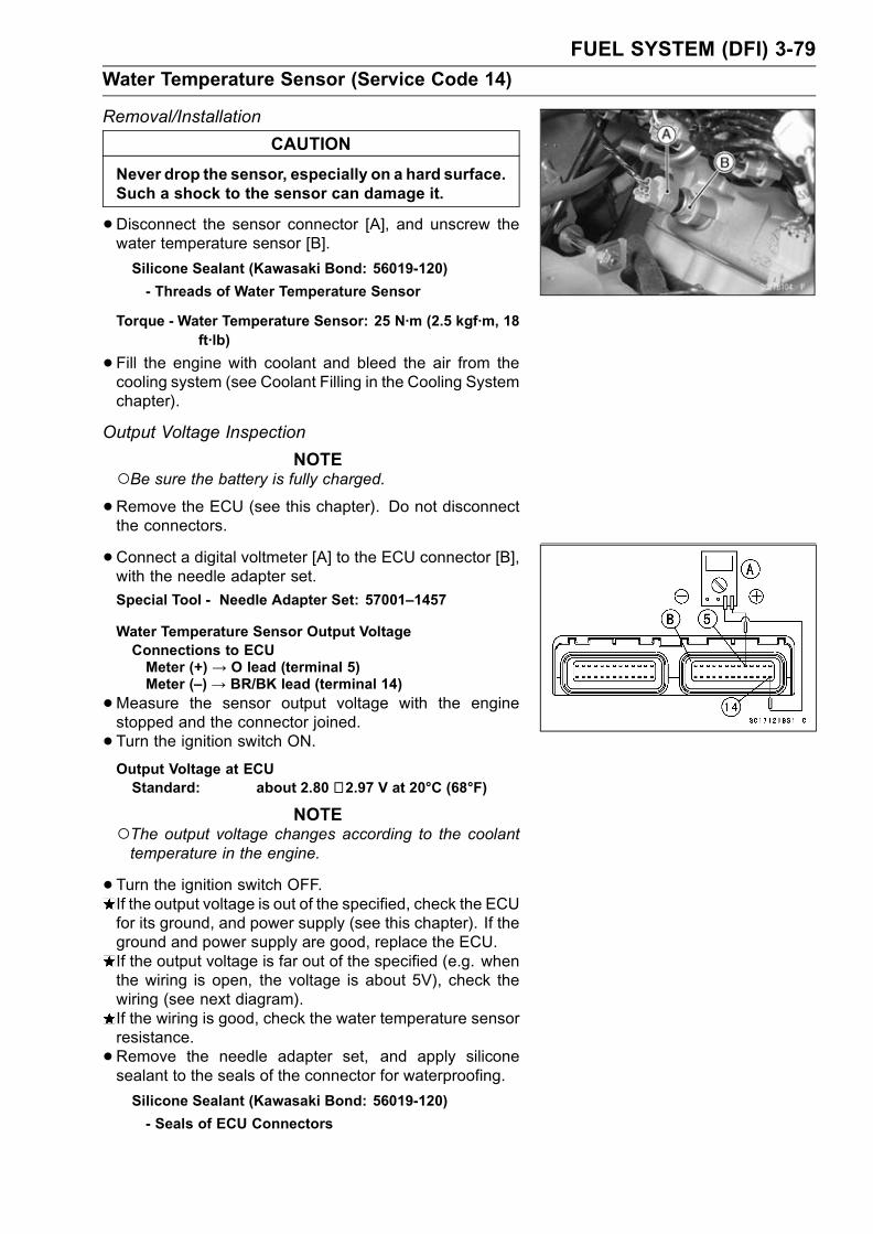
FUEL SYSTEM (DFI) 3-79
Water Temperature Sensor (Service Code 14)
Removal/Installation
CAUTION
Never drop the sensor, especially on a hard surface.Such a shock to the sensor can damage it.
•Disconnect the sensor connector [A], and unscrew thewater temperature sensor [B].
Silicone Sealant (Kawasaki Bond: 56019-120)
- Threads of Water Temperature Sensor
Torque - Water Temperature Sensor: 25 N·m (2.5 kgf·m, 18ft·lb)
•Fill the engine with coolant and bleed the air from thecooling system (see Coolant Filling in the Cooling Systemchapter).
Output Voltage Inspection
NOTEBe sure the battery is fully charged.•Remove the ECU (see this chapter). Do not disconnectthe connectors.
•Connect a digital voltmeter [A] to the ECU connector [B],with the needle adapter set.
Special Tool - Needle Adapter Set: 57001–1457
Water Temperature Sensor Output VoltageConnections to ECUMeter (+) → O lead (terminal 5)Meter (–)→ BR/BK lead (terminal 14)
•Measure the sensor output voltage with the enginestopped and the connector joined.
• Turn the ignition switch ON.Output Voltage at ECUStandard: about 2.80 ∼ 2.97 V at 20°C (68°F)
NOTEThe output voltage changes according to the coolanttemperature in the engine.
•Turn the ignition switch OFF.If the output voltage is out of the specified, check the ECUfor its ground, and power supply (see this chapter). If theground and power supply are good, replace the ECU.If the output voltage is far out of the specified (e.g. whenthe wiring is open, the voltage is about 5V), check thewiring (see next diagram).If the wiring is good, check the water temperature sensorresistance.
•Remove the needle adapter set, and apply siliconesealant to the seals of the connector for waterproofing.
Silicone Sealant (Kawasaki Bond: 56019-120)
- Seals of ECU Connectors
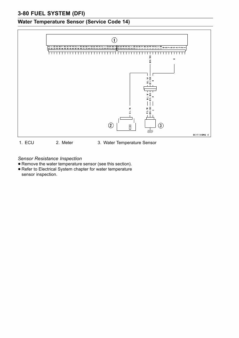
3-80 FUEL SYSTEM (DFI)
Water Temperature Sensor (Service Code 14)
1. ECU 2. Meter 3. Water Temperature Sensor
Sensor Resistance Inspection
•Remove the water temperature sensor (see this section).•Refer to Electrical System chapter for water temperaturesensor inspection.

FUEL SYSTEM (DFI) 3-81
Atmospheric Pressure Sensor (Service Code 15)
CAUTION
Never drop the sensor, especially on a hard surface.Such a shock to the sensor can damage it.
Removal
•Turn the ignition switch off.• Remove:Air Cleaner Housing (see Air Cleaner Housing Removal)Atmospheric Pressure Sensor Connector [A]Atmospheric Pressure Sensor Screw [B]Atmospheric Pressure Sensor [C]
Installation
NOTEThe atmospheric pressure sensor is the same part asthe inlet air pressure sensor except that the inlet airpressure sensor has a inlet air pressure hose and dif-ferent wiring.
• Installation is reverse of removal.• Tighten the sensor bolts.Torque - Atmospheric Pressure Sensor Screw: 4.9 N·m
(0.50 kgf·m, 43 in·lb)
Input Voltage Inspection
NOTEBe sure the battery is fully charged.The inspection is the same as “Input Voltage Inspection”of the throttle sensor and the inlet air pressure sensor.
•Turn the ignition switch OFF.•Remove the ECU (see this chapter). Do not disconnectthe ECU connectors.
•Connect a digital voltmeter [A] to the connector [B], withthe needle adapter set.
Special Tool - Needle Adapter Set: 57001–1457
Atmospheric Pressure Sensor Input VoltageConnections to ECU
Meter (+) → BL lead (terminal 1)
Meter (–)→ BR/BK lead (terminal 14)
•Measure the input voltage with the engine stopped, andwith the connectors joined.
• Turn the ignition switch ON.Input Voltage at ECUStandard: 4.75 ∼ 5.25 V DC
If the reading of input voltage is less than the standardrange, check the ECU for its ground, and power supply(see this chapter). If the ground and power supply aregood, replace the ECU.

3-82 FUEL SYSTEM (DFI)
Atmospheric Pressure Sensor (Service Code 15)
If the reading is within the standard range, remove theseat cover, and check the input voltage again at the sen-sor connector.Remove the air cleaner housing (see Air Cleaner HousingRemoval).
• Disconnect the atmospheric pressure sensor connectorand connect the harness adapter [A] between the mainharness connector and pressure sensor connector.
•Connect a digital meter to the harness adapter leads.[B] Atmospheric Pressure Sensor
Special Tool - Sensor Harness Adapter: 57001–1561
Atmospheric Pressure Sensor Input VoltageConnections to Sensor
Meter (+) → BL lead [C]
Meter (–) → BR/BK lead [D]
•Measure the input voltage with the engine stopped, andwith the connector joined.
• Turn the ignition switch ON.Input Voltage at Sensor ConnectorStandard: 4.75 ∼ 5.25 V DC
If the reading is out of the standard range, check thewiring (see wiring diagram in this section).If the reading is good, the input voltage is normal. Checkthe output voltage.
• Turn the ignition switch OFF.Output Voltage Inspection
•Measure the output voltage at the ECU in the same wayas input voltage inspection. Note the following.Digital Meter [A]ECU Connector [B]
Atmospheric Pressure Sensor Output VoltageConnections to ECU
Meter (+) → G/W lead (terminal 4)
Meter (–) → BR/BK lead (terminal 14)
Output VoltageUsable Range: 3.80 ∼ 4.20 V DC at the standard
atmospheric pressure (101.32 kPa,76 cmHg abs.)
NOTEThe output voltage changes according to the local at-mospheric pressure.The atmospheric sensor output voltage is based ona nearly perfect vacuum in the small chamber of thesensor. So, the sensor indicates absolute atmosphericpressure.
If the output voltage is within the usable range, check theECU for its ground, and power supply (see this chapter). Ifthe ground and power supply are good, replace the ECU.

FUEL SYSTEM (DFI) 3-83
Atmospheric Pressure Sensor (Service Code 15)
If the output voltage is far out of the usable range, removethe fuel tank, and check the output voltage at the sensorconnector [A] (when the wiring is open, the output voltageis about 1.8 V).
•Connect a digital meter [A] to the harness adapter leads.[B] Atmospheric Pressure Sensor
Special Tool - Sensor Harness Adapter: 57001–1561
Atmospheric Pressure Sensor Output VoltageConnections to Sensor
Meter (+) → G/W lead [C]
Meter (–) → BR/BK lead [D]
Output Voltage at SensorUsable Range: 3.80 ∼ 4.20 V DC at the standard
atmospheric pressure (101.32 kPa,76 cmHg abs)
If the output voltage is normal, check the wiring for conti-nuity (see next diagram).If the output voltage is out of the usable range, replacethe sensor.
1. ECU 2. Atmospheric Pressure Sensor
If you need to check the atmospheric pressure sensor forvarious altitudes other than sea level, check the outputvoltage as follows:Determine the local altitude (elevation).

3-84 FUEL SYSTEM (DFI)
Atmospheric Pressure Sensor (Service Code 15)
If you know the local atmospheric pressure using abarometer, substitute the atmospheric pressure for throt-tle vacuum pressure in the inlet air pressure sensor chart(see intake Air Pressure Sensor section in this chapter).And get the usable range of the atmospheric pressuresensor output voltage and check if output voltage iswithin the standard or not in the same way as OutputVoltage Inspection of the inlet air pressure sensor.If you know the local altitude, use the following chart.
Atmospheric Pressure/Altitude Relationship

FUEL SYSTEM (DFI) 3-85
Crankshaft Sensor (Service Code 21)
Start the engine and switch the diagnosis mode to Dealer1 mode to know all the problem that the DFI system has atthe time of self-diagnosis. If the engine cannot be started,the self-diagnosis system does not detect dynamic condi-tion of the crankshaft sensor. In this case turn off the igni-tion switch and turn it on again to enter the Dealer 2 mode.In this mode the system tells all the troubles which the DFIsystem had in both static and dynamic conditions.
Crankshaft Sensor Removal/Installation
•See the Ignition System section in the Electrical Systemchapter.
Crankshaft Sensor InspectionThe crankshaft have no power source, and when the en-gine stops, the crankshaft generates no signals.
•Crank the engine and measure the peak voltage of thecrankshaft sensor (see Electrical System chapter) in or-der to check the sensor.
•Check the wiring for continuity, using the following dia-gram.
1. ECU 2. Crankshaft Sensor

3-86 FUEL SYSTEM (DFI)
Camshaft Position Sensor (Service Code 23)
Start the engine and switch the diagnosis mode to Dealer1 mode to know all the problem that the DFI system has atthe time of self-diagnosis. If the engine cannot be started,the self-diagnosis system does not detect dynamic condi-tion of the camshaft position sensor. In this case turn offthe ignition switch and turn it on again to enter the Dealer 2mode. In this mode the system tells all the troubles whichthe DFI system had in both static and dynamic conditions.
Camshaft Position Sensor Removal/InstallationThe camshaft position sensor detects the position of the
camshaft, and distinguishes the cylinder.
• See the Ignition system section in the Electric Systemchapter.
Camshaft Position Sensor InspectionThe camshaft position sensor have no power source, andwhen the engine stops, the camshaft position sensor gen-erates no signal.
• Crank the engine and measure the peak voltage of thecamshaft position sensor (see Electrical System chapter)in order to check the sensor.
•Check the wiring for continuity, using the following dia-gram.
1. ECU 2. Camshaft Position Sensor

FUEL SYSTEM (DFI) 3-87
Speed Sensor (Service Code 24, 25)
Speed Sensor Removal/Installation
•See the Switches and Sensors section in teh ElectricalSystem chapter.
Speed Sensor Inspection
•See the Switches and Sensors section in teh ElectricalSystem chapter.
Input Voltage Inspection
NOTEBe sure the battery is fully charged.•Turn the ignition switch OFF.•Remove the fuel tank (see Fuel Tank Removal).• Disconnect the speed sensor connector [A] and connectthe harness adapter [B] between the harness connectorand speed sensor connector.
•Connect a digital meter to the harness adapter leads.Special Tool - Throttle Sensor Setting Adapter:
57001-1400
Speed Sensor Input VoltageConnector to Sensor
Meter (+) → P lead [C]
Meter (−) → BK lead [D]
•Measure the sensor input voltage with the enginestopped, and with the connector joined.
• Turn the ignition switch ON.Input Voltage at SensorStandard: About 9 ∼ 11 V DC at Ignition SW ON
If the reading is out of the range, check the wiring (seewiring diagram in this section), and meter (see ElectricalSystem chapter).If the reading is good, check the output voltage.
• Turn the ignition switch OFF.Output Voltage Inspection
•Before this inspection, inspect the input voltage (see InputVoltage Inspection).
NOTEBe sure the battery is fully charged.•Turn the ignition switch OFF.

3-88 FUEL SYSTEM (DFI)
Speed Sensor (Service Code 24, 25)
•Disconnect the speed sensor connector [A] and connectthe harness adapter [B] between the harness connectorand speed sensor connector.
•Connect a digital meter to the harness adapter leads.Special Tool - Throttle Sensor Setting Adapter: 57001
-1400
Throttle Sensor Output VoltageConnections to Sensor
Meter (+) → Y lead [C]
Meter (–) → BK lead [D]
•Measure the sensor output voltage with the enginestopped, and with the connector joined.
• Turn the ignition switch ON.Output Voltage at SensorStandard: About 0.05 ∼ 0.07 V DC
NOTEIf you can rotate the engine sprocket, the output voltagewill be raise.
If the reading is out of the range, check the speed sensor(see Electrical System chapter) and the wiring to ECU(see wiring diagram in this section).If the reading, speed sensor and wiring are good, replacethe ECU.
1. ECU 2. Meter Assembly 3. Speed Sensor

FUEL SYSTEM (DFI) 3-89
Vehicle-down Sensor (Service Code 31)
This sensor has a weight [A] with two magnets inside, andsends a signal to the ECU. But when the motorcycle banks60 ∼ 70° or more to either side (in fact falls down), the weightturns and shuts off the signal. The ECU senses this change,and stops the fuel pump, the fuel injectors, and the ignitionsystem.Hall IC [B]When the motorcycle is down, the ignition switch is left
ON. If the starter button is pushed, the electric starter turnsbut the engine doesn’t start. To start the engine again, raisethe motorcycle, turn the ignition switch OFF, and then ON.When the ignition switch is turned ON, current flows throughthe latch-up circuit and the transistor in the circuit is turnedON to unlock the latch-up circuit.Vehicle-down Sensor [A]Ground Terminal BK/Y [B]Output Terminal Y/G [C]Power Source Terminal W/Y [D]
Removal
CAUTION
Never drop the down-sensor, especially on a hardsurface. Such a shock to the sensor can damage it.
•Remove:Fuel Tank (see Fuel Tank Removal)Connector [A]Bolts [B]Vehicle-down Sensor [C] and Washers
Installation
•The UP mark [A] of the sensor should face upward.WARNING
Incorrect installation of the vehicle-down sensorcould cause sudden loss of engine power. Therider could lose balance during certain riding situ-ations, like leaning over in a turn, with the potentialfor an accident resulting in injury or death. Ensurethat the down sensor is held in place by the sensorbrackets.
Inspection
NOTEBe sure the battery is fully charged.•Remove:Fuel Tank (see Fuel Tank Removal)

3-90 FUEL SYSTEM (DFI)
Vehicle-down Sensor (Service Code 31)
•Connect a digital volt meter [A] to the connector of thevehicle-down sensor [B], with the needle adapter set [C].
Vehicle-down Sensor Power Source VoltageConnections to Sensor
Meter (+) → W/Y lead [D]
Meter (–) → BK/Y lead [E]
•Turn the ignition switch ON, and measure the powersource voltage with the connector joined.
Power Source Voltage at SensorStandard: Battery Voltage (12.5 V or more)
•Turn the ignition switch OFF.If there is no battery voltage, check the following:Battery (see Electrical System chapter)ECU Main Fuse 15 AWiring for Vehicle-down Sensor Power Source (see nextdiagram)If the power source is normal, check the output voltage.
• Turn the ignition switch OFF.•Remove the sensor.•Connect a digital volt meter [A] to the connector, with nee-dle adapter set [B].
Special Tool - Needle Adapter Set: 57001–1457
Vehicle-down Sensor Output VoltageConnections to Sensor
Meter (+) → Y/G lead [D]
Meter (–) → BK/Y lead [E]
•Hold the sensor vertically.• Turn the ignition switch ON, and measure the output volt-age with the connector joined.Tilt the sensor 60 ∼ 70° or more [C] right or left, then holdthe sensor almost vertical with the arrow mark pointed up,and measure the output voltage.
Output Voltage at SensorStandard: with sensor tilted 60 ∼ 70° or more
right or left: 3.7 ∼ 4.4 Vwith sensor arrow mark pointed up:0.4 ∼ 1.4 V
NOTEIf you need to test again, turn the ignition switch OFF,and then ON.

FUEL SYSTEM (DFI) 3-91
Vehicle-down Sensor (Service Code 31)
•Turn the ignition switch OFF.•Remove the needle adapter set, and apply siliconesealant to the seals of the connector for waterproofing.
Silicone Sealant (Kawasaki Bond: 56019-120)
- Seals of Vehicle-down Sensor Connector
If the output voltage is normal, the wiring is suspect.Check the wiring.If the wiring is good, check the ECU for its ground andpower supply (see this chapter). If the ground and powersupply are good, replace the ECU.If the output voltage is out of the specified, replace thevehicle-down sensor.
1. ECU2. Ignition Switch3. ECU Main Relay
4. ECU Main Fuse 15 A5. Vehicle-down Sensor6. Main Fuse 30 A
7. Starter Relay8. Battery

3-92 FUEL SYSTEM (DFI)
Subthrottle Sensor (Service Code 32)
The subthrottle sensor is a rotating variable resistor thatchange output voltage according to throttle operating. TheECU senses this voltage change and determines fuel injec-tion quantity, and ignition timing according to engine rpm,and throttle opening.Input Terminal [A]Output Terminal [B]Ground Terminal [C]
Subthrottle Sensor Removal/Adjustment
CAUTION
Do not remove or adjust the subthrottle sensor [A]since it has been adjusted and set with precision atthe factory.Never drop the sensor, especially on a hard surface.Such a shock to the sensor can damage it.
Subthrottle Sensor Connector [B]
Input Voltage Inspection
NOTEBe sure the battery is fully charged.The inspection is the same as “Input Voltage Inspection”of the vacuum sensor and the atmospheric pressuresensor.
•Turn the ignition switch OFF.•Remove the ECU (see this chapter). Do not disconnectthe ECU connectors.
•Connect a digital voltmeter [A] to the connector [B], usingthe needle adapter set.
Special Tool - Needle Adapter Set: 57001–1457
Subthrottle Sensor Input VoltageConnections to ECU Connector
Meter (+)→ BL lead (terminal 1)
Meter (–)→ BR/BK lead (terminal 14)
•Measure the input voltage with the engine stopped, andwith the connectors joined.
• Turn the ignition switch ON.Input Voltage at ECU Connector
Standard: 4.75 ∼ 5.25 V DC
•Turn the ignition switch OFF.If the reading of input voltage is less than the standard,check the ECU for its ground, power supply and wiringshorted.If the input voltage is within the standard range, check theinput voltage at the subthrottle sensor connector.
•Remove the throttle body assembly temporarily (seeThrottle Body Assy Removal).
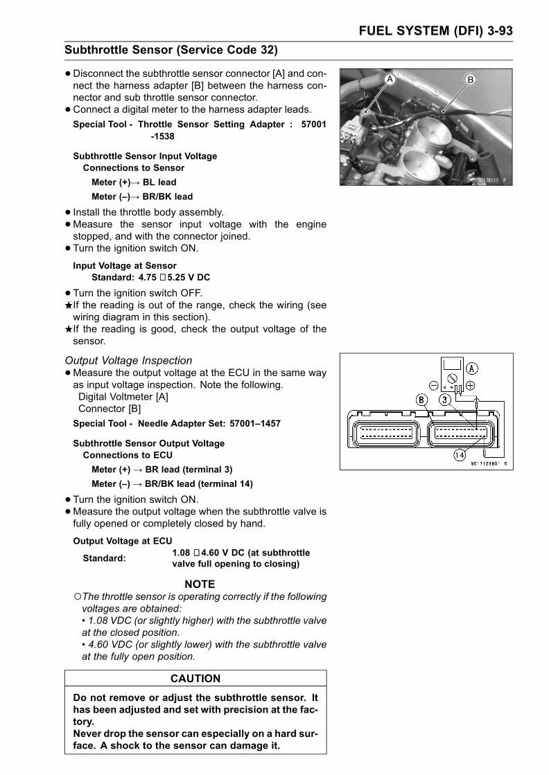
FUEL SYSTEM (DFI) 3-93
Subthrottle Sensor (Service Code 32)
•Disconnect the subthrottle sensor connector [A] and con-nect the harness adapter [B] between the harness con-nector and sub throttle sensor connector.
•Connect a digital meter to the harness adapter leads.Special Tool - Throttle Sensor Setting Adapter : 57001
-1538
Subthrottle Sensor Input VoltageConnections to Sensor
Meter (+)→ BL lead
Meter (–)→ BR/BK lead
• Install the throttle body assembly.•Measure the sensor input voltage with the enginestopped, and with the connector joined.
• Turn the ignition switch ON.Input Voltage at Sensor
Standard: 4.75 ∼ 5.25 V DC
•Turn the ignition switch OFF.If the reading is out of the range, check the wiring (seewiring diagram in this section).If the reading is good, check the output voltage of thesensor.
Output Voltage Inspection
•Measure the output voltage at the ECU in the same wayas input voltage inspection. Note the following.Digital Voltmeter [A]Connector [B]
Special Tool - Needle Adapter Set: 57001–1457
Subthrottle Sensor Output VoltageConnections to ECU
Meter (+)→ BR lead (terminal 3)
Meter (–)→ BR/BK lead (terminal 14)
•Turn the ignition switch ON.•Measure the output voltage when the subthrottle valve isfully opened or completely closed by hand.
Output Voltage at ECU
Standard:1.08 ∼ 4.60 V DC (at subthrottlevalve full opening to closing)
NOTEThe throttle sensor is operating correctly if the followingvoltages are obtained:• 1.08 VDC (or slightly higher) with the subthrottle valveat the closed position.• 4.60 VDC (or slightly lower) with the subthrottle valveat the fully open position.
CAUTION
Do not remove or adjust the subthrottle sensor. Ithas been adjusted and set with precision at the fac-tory.Never drop the sensor can especially on a hard sur-face. A shock to the sensor can damage it.

3-94 FUEL SYSTEM (DFI)
Subthrottle Sensor (Service Code 32)
If the output voltage is within the standard range, checkthe ECU for a good ground, and power supply (see thischapter). If the ground and power supply are good, re-place the ECU.If the output voltage is far out of the standard range (e.g.when the wiring is open, the reading is 0 V), check theoutput voltage again at the sensor connector.
•Disconnect the subthrottle sensor connector [A] and con-nect the harness adapter [B] between the harness con-nector and sub throttle sensor connector.
•Connect a digital meter to the harness adapter leads.Special Tool - Throttle Sensor Harness Adapter :
57001–1538
Subthrottle Sensor Output VoltageConnections to Sensor
Meter (+) → BR lead
Meter (–) → BR/BK lead
•Measure the sensor output voltage with the enginestopped, and with the connector joined.
• Turn the ignition switch ON.•Measure the output voltage when the subthrottle valve isfully opened or completely closed by hand.
Output Voltage at SensorStandard: 1.08 ∼ 4.60 V DC (at subthrottle valve
full opening to closing)
NOTEThe throttle sensor is operating correctly if the followingvoltages are obtained:• 1.08 VDC (or slightly higher) with the subthrottle valveat the closed position.• 4.60 VDC (or slightly lower) with the subthrottle valveat the fully open position.
CAUTION
Do not remove or adjust the subthrottle sensor. Ithas been adjusted and set with precision at the fac-tory.Never drop the sensor, especially on a hard surface.A shock to the sensor can damage it.
NOTEThe standard voltage marked with an asterisk refers tothe value when the voltage reading at the Input VoltageInspection shows 5V exactly.When the input voltage reading shows other than 5V,derive a voltage range as follows.Example:In the case of a input voltage of 4.75 V.1.08 × 4.75 ÷ 5.00 = 1.03 V4.60 × 4.75 ÷ 5.00 = 4.37 VThus, the valid range is 1.03 ∼ 4.37 V

FUEL SYSTEM (DFI) 3-95
Subthrottle Sensor (Service Code 32)
•After subthrottle sensor voltage inspection, remove theharness adapter.If the reading is out of the standard range, inspect thethrottle sensor resistance.If the output voltage is normal, check the wiring for conti-nuity (see next diagram).
Resistance Inspection
•Turn the ignition switch OFF.•Disconnect the subthrottle sensor connector.•Connect a digital meter [A] to the subthrottle sensor con-nector [B].
•Measure the main throttle sensor resistance.Throttle Sensor ResistanceConnections: BL lead [C]←→ BR/BK lead [D]
Standard: 4 ∼ 6 kΩIf the reading is out of the range, replace the throttle bodyassy.If the reading is within the range, but the problem stillexists, replace the ECU (see this chapter).
1. ECU2. Subthrottle Valve Actuator3. Subthrottle Sensor4. Main Throttle Sensor

3-96 FUEL SYSTEM (DFI)
Stick Coils (#1, #2, #3, #4: Service Code 51, 52, 53, 54)
Stick Coil #1: Ignition Coil (Service Code 51)Stick Coil #2: Ignition Coil (Service Code 52)Stick Coil #3: Ignition Coil (Service Code 53)Stick Coil #4: Ignition Coil (Service Code 54)
Removal/Installation
CAUTION
Never drop the ignition coils, especially on a hardsurface. Such a shock to the ignition coil can dam-age it.
•See Ignition System section in the Electrical Systemchapter.
Input Voltage Inspection
NOTEBe sure the battery is fully charged.
•Turn the ignition switch OFF.•Remove the ECU (see this chapter). Do not disconnectthe ECU connector.
•Connect a digital voltmeter [A] as shown, with the needleadapter set [B].Measure the input voltage to each primary winding of theignition coils with the engine stopped, and with the con-nectors joined.
• Turn the ignition switch ON.Stick Coil Input Voltage at ECUConnections for Stick Coil #1
Meter (+) → BK lead (terminal 39)
Meter (–) → BK/Y lead (terminal 51)
Connections for Stick Coil #2
Meter (+)→ BK/G lead (terminal 38)
Meter (–) → BK/Y lead (terminal 51)
Connections for Stick Coil #3
Meter (+)→ BK/W lead (terminal 37)
Meter (–) → BK/Y lead (terminal 51)
Connections for Stick Coil #4
Meter (+)→ BK/O lead (terminal 52)
Meter (–) → BK/Y lead (terminal 51)
Input Voltage at ECUStandard: Battery Voltage (12.5 V or more)
If the reading is out of the standard, check the wiring (seenext wiring diagram).If the reading is good, the input voltage is normal. Crankthe engine, and check the peak voltage of the stick coils(see Electrical System chapter) in order to check the pri-mary coils.

FUEL SYSTEM (DFI) 3-97
Stick Coils (#1, #2, #3, #4: Service Code 51, 52, 53, 54)
1. ECU2. Stick Coil #13. Stick Coil #24. Stick Coil #3
5. Stick Coil #46. Ignition Switch7. Engine Stop Switch8. Junction Box
9. Ignition Fuse 10 A10. Main Fuse 30 A11. Starter Relay12. Battery

3-98 FUEL SYSTEM (DFI)
Subthrottle Valve Actuator (Service Code 62)
Subthrottle Valve Actuator Removal
CAUTION
Do not remove the subthrottle valve actuator [A]since it has been adjusted and set with precisionat the factory.Never drop the actuator , especially on a hard sur-face. Such a shock to the actuator can damage it.
Subthrottle Valve Actuator Inspection
•Remove the air cleaner housing (see Air Cleaner HousingRemoval).
• Turn the ignition switch ON.•Check to see that all subthrottle valves [A] open and closesmoothly.If the subthrottle valves do not operate, check the actuatorinternal resistance (see Resistance Inspection).
Resistance Inspection
•Turn the ignition switch OFF.•Disconnect the subthrottle valve actuator connector [A].
• Connect a digital meter to the subthrottle valve actuatorconnector [A].
•Measure the subthrottle valve actuator resistance.Subthrottle Valve Actuator ResistanceConnections: BK lead [1]←→ P lead [2]
G lead [3]←→ W/BL lead [4]
Standard: About 5 ∼ 7 ΩIf the reading is out of the range, replace the throttle bodyassy.If the reading is within the range, check the input voltage(see Input Voltage Inspection).
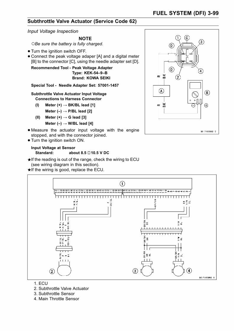
FUEL SYSTEM (DFI) 3-99
Subthrottle Valve Actuator (Service Code 62)
Input Voltage Inspection
NOTEBe sure the battery is fully charged.•Turn the ignition switch OFF.•Connect the peak voltage adaper [A] and a digital meter[B] to the connector [C], using the needle adapter set [D].
Recommended Tool - Peak Voltage AdapterType: KEK-54–9–BBrand: KOWA SEIKI
Special Tool - Needle Adapter Set: 57001-1457
Subthrottle Valve Actuator Input VoltageConnections to Harness Connector
(I) Meter (+) → BK/BL lead [1]
Meter (–) → P/BL lead [2]
(II) Meter (+) → G lead [3]
Meter (–) → W/BL lead [4]
•Measure the actuator input voltage with the enginestopped, and with the connector joined.
• Turn the ignition switch ON.Input Voltage at SensorStandard: about 8.5 ∼ 10.5 V DC
If the reading is out of the range, check the wiring to ECU(see wiring diagram in this section).If the wiring is good, replace the ECU.
1. ECU2. Subthrottle Valve Actuator3. Subthrottle Sensor4. Main Throttle Sensor
3-100 FUEL SYSTEM (DFI)
Throttle Grip and Cables
Free Play Inspection
•Refer to the Throttle Control System Inspection in the Pe-riodic Maintenance chapter.
Free Play Adjustment
•Refer to the Throttle Control System Inspection in the Pe-riodic Maintenance chapter.
Cable Installation
• Install the throttle cables in accordance with the CableRouting section in the Appendix chapter.
• Install the lower ends of the throttle cables in the cablebracket on the throttle assy after installing the upper endsof the throttle cables in the grip.
• After installation, adjust each cable properly.WARNING
Operation with incorrectly routed or improperly ad-justed cables could result in an unsafe riding con-dition.
Cable Lubrication
•Refer to the General Lubrication Perform in the PeriodicMaintenance chapter.

FUEL SYSTEM (DFI) 3-101
Choke Cable
Free Play Inspection
•Push the choke lever [A] all the way to the front.• Check choke cable free paly [B].Determine the amount of choke cable play at the chokelever. Pull the choke lever till just before the inner cable[C] moves the link lever [D]; the amount of choke levertravel is the amount of cable play.If the free play is incorrect, adjust the choke cable.
Choke Cable Free PlayStandard: 2 ∼ 3 mm (0.08 ∼ 0.12 in)
Free Play Adjustment
•Loosen the locknut [A], and turn the adjuster [B] until thecable has the proper amount of free play.
• Tighten the locknut securely.
Choke Cable Installation
• Install the choke cable in accordance with the Cable Rout-ing section in the General Information chapter.
• After installation, adjust the cable properly.WARNING
Operation with an incorrectly routed or improperlyadjusted cable could result in an unsafe riding con-dition.
Cable Lubrication
•Refer to the General Lubrication Perform in the PeriodicMaintenance chapter.

3-102 FUEL SYSTEM (DFI)
Throttle Body Assy
Idle Speed Inspection
•Refer to the Idle Speed Inspection in the Periodic Main-tenance chapter .
Throttle Bore Cleaning
•Refer to the Throttle Control System Inspection in the Pe-riodic Maintenance chapter.
Synchronization Inspection
•Refer to the Engine Vacuum Synchronization Inspectionin the Periodic Maintenance chapter.
Synchronization Adjustment
•Refer to the Engine Vacuum Synchronization Inspectionin the Periodic Maintenance chapter.
Throttle Body Assy Removal
WARNINGGasoline is extremely flammable and can be ex-plosive under certain conditions. Turn the ignitionswitch OFF. Disconnect the battery (–) cable ter-minal. Do not smoke. Make sure the area iswell-ventilated and free from any source of flameor sparks; this includes any appliance with a pilotlight.Be prepared for fuel spillage: any spilled fuel mustbe completely wiped up immediately.
•Remove:Fuel Tank (see Fuel Tank Removal)Air Cleaner Housing (see Air Cleaner Housing Removal)
• Be sure to place a piece of cloth around the fuel supplypipe [A] of the throttle body assembly.
•Remove:Gray Connectors [B]Water Temperature Sensor Connector [C]
•Remove:Vacuum Switch Valve Vacuum HoseVacuum Hose [A] (California model)
• Loosen:Clamp Bolts [B]
Special Tool - Carburetor Drain Plug Wrench, Hex 3:57001-1269
•Remove the throttle body assembly [C] from holder.

FUEL SYSTEM (DFI) 3-103
Throttle Body Assy
•Remove:Choke Cable Lower End [A]
•Remove the throttle case to make a throttle cable slack.•Remove:Throttle Cable Lower Ends [B]
• After removing the throttle body assy, stuff pieces of lint-free, clean cloths into the throttle body holders.
CAUTION
If dirt gets into the engine, excessive engine wearand possible engine damage will occur.
Throttle Body Assy Installation
• Install the holder clamp bolts [A] in the direction as shown.[B] Bolt Heads
• Tighten:Torque - Throttle Body Assembly Holder Clamp Bolts: 3.0
N·m (0.31 kgf·m, 27 in·lb)
•Run the vacuum hoses as shown in the Cable, Wire, andHose Routing section of the Appendix chapter.
•When installing the fuel hose, refer to Fuel Tank Installa-tion.
• Adjust:Throttle Grip Free PlayChoke Lever Free PlayIdle Speed

3-104 FUEL SYSTEM (DFI)
Throttle Body Assy
Throttle Body Assy Disassembly
1. Throttle Body Assy 5. Inlet Air Pressure Sensor Hoses
2. Injectors 6. Bands
3. Injector Connector Harness
4. Delivery Pipe Assy
CAUTION
Do not remove, disassemble or adjust the mainthrottle sensor, subthrottle sensor, subthrottlevalve actuator, throttle link mechanism and throttlebody assy, because they are adjust or set surely atthe manufacturer. Adjustment of these parts couldresult in poor performance, requiring replacementof the throttle body assy.
•Remove the throttle body assembly (see Throttle BodyAssy Removal).
• Pressing the tabs [A] of each injector connectors, pull outthe each connectors.
•Remove the screws [B] to pull out the injector assys fromthe throttle body assy together with the delivery pipe [C].
NOTEDo not damage the part of insert of the injectors whenthey are pulled out from the throttle body.

FUEL SYSTEM (DFI) 3-105
Throttle Body Assy
•Pull out the injectors [A] from the delivery pipe [B].
NOTEDo not damage the part of insert of the injectors whenthey are pulled out from the delivery pipe.
Throttle Body Assy Assembly
•Before assembling, blow away dirt or dust from the throttlebody and delivery pipe by applying compressed air.
• Apply daphne oil or engine oil to the new O-rings [A] ofeach injector, insert them to the delivery pipe [B] and con-firm whether the injectors turn smoothly or not.
NOTEReplace the O-ring of injectors and the dust seals ofdelivery pipe to new one.
•Apply daphne oil or engine oil to the new dust seals [A], in-sert the injectors installed to the delivery pipe to the throt-tle body.
NOTEReplace the dust seals of the throttle body to new one.• Install the delivery pipe assy to the throttle body.Torque - Fuel Delivery Pipe Mounting Screws: 3.4 N·m
(0.35 kgf·m, 30 in·lb)
• Install the injector connectors to each injector, and bindthe connector lead with clamps [A].
• Insert the each hoses to the throttle body fittings.• Install the throttle body assy (see Throttle Body Assy In-stallation).

3-106 FUEL SYSTEM (DFI)
Air Line
Element Removal
•Refer to Air Cleaner Element Replacement in the PeriodicMaintenance chapter.
Element Installation
•Refer to Air Cleaner Element Replacement in the PeriodicMaintenance chapter.
Air Cleaner Element Inspection
•Visually check the element [A] for tears or breaks.If the element has any tears or breaks, replace the ele-ment.
Oil DrainingA drain hose is connected to the bottom of the air cleaner
part to drain water or oil accumulated in the cleaner part.
• Visually check the catch tank [A] of the drain hose if thewater or oil accumulates in tank.If any water or oil accumulates in the tank, remove thetank from the drain hose and drain it.
WARNINGBe sure reinstall the catch tank in the drain hoseafter draining. Oil on tires will make them slipperyand can cause an accident and injury.
Air Inlet Duct Removal
•Remove:Upper Fairing (see Frame chapter)Mounting Bolts [A]Air Inlet Duct [B]
Air Inlet Duct Installation
•Tighten:Torque - Air Inlet Duct Mounting Bolts: 6.9 N·m (0.70 kgf·m,
61 in·lb)

FUEL SYSTEM (DFI) 3-107
Fuel Tank
Fuel Tank Removal
WARNINGGasoline is extremely flammable and can be explo-sive under certain conditions. Make sure the areais well-ventilated and free from any source of flameor sparks; this includes any appliance with a pilotlight. Do not smoke. Turn the ignition switch OFF.Be prepared for fuel spillage; any spilled fuel mustbe completely wiped up immediately.
CAUTION
For California model, if gasoline, solvent, water orany other liquid enters the canister, the canister’svapor absorbing capacity is greatly reduced. If thecanister does become contaminated, replace it witha new one.
•Remove:Seats (see Frame chapter)Fuel Tank Bolts [A]Drain Hose [B]
•Open the fuel tank cap to lower the pressure in the tank.
•Disconnect the fuel pump lead connector [A].• Be sure to place a piece of cloth around the fuel hose joint[B].
•While pinching the hose joint locks [C] with fingers, pullthe joint out along the delivery pipe.
WARNINGBe prepared for fuel spillage; any spilled fuel mustbe completely wiped up immediately.When the fuel hose is disconnected, fuel spills outfrom the hose and the pipe because of residualpressure. Cover the hose connection with a pieceof clean cloth to prevent fuel spillage.
•Remove the fuel tank, and place it on a flat surface.
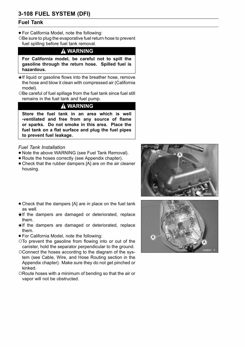
3-108 FUEL SYSTEM (DFI)
Fuel Tank
•For California Model, note the following:Be sure to plug the evaporative fuel return hose to preventfuel spilling before fuel tank removal.
WARNINGFor California model, be careful not to spill thegasoline through the return hose. Spilled fuel ishazardous.
If liquid or gasoline flows into the breather hose, removethe hose and blow it clean with compressed air (Californiamodel).Be careful of fuel spillage from the fuel tank since fuel stillremains in the fuel tank and fuel pump.
WARNINGStore the fuel tank in an area which is well-ventilated and free from any source of flameor sparks. Do not smoke in this area. Place thefuel tank on a flat surface and plug the fuel pipesto prevent fuel leakage.
Fuel Tank Installation
•Note the above WARNING (see Fuel Tank Removal).• Route the hoses correctly (see Appendix chapter).• Check that the rubber dampers [A] are on the air cleanerhousing.
•Check that the dampers [A] are in place on the fuel tankas well.If the dampers are damaged or deteriorated, replacethem.If the dampers are damaged or deteriorated, replacethem.
• For California Model, note the following:To prevent the gasoline from flowing into or out of thecanister, hold the separator perpendicular to the ground.Connect the hoses according to the diagram of the sys-tem (see Cable, Wire, and Hose Routing section in theAppendix chapter). Make sure they do not get pinched orkinked.Route hoses with a minimum of bending so that the air orvapor will not be obstructed.

FUEL SYSTEM (DFI) 3-109
Fuel Tank
•Connect the fuel pump lead connector [A].• Insert the fuel hose joint [B] straight onto the delivery pipeuntil the hose joint clicks.
• Push and pull [C] the hose joint [B] back and forth, andmake sure it is locked and does not come off. When thehose joint is correctly installed, it should slide on the de-livery pipe about 5 mm (0.2 in.).If it does not slide, reinstall the hose joint.
WARNINGMake sure the hose joint is installed correctly on thedelivery pipe by sliding the joint, or the fuel couldleak.
Fuel Tank Inspection
•Remove the hose(s) from the fuel tank, and open the tankcap.
•Check to see if the water drain pipe [B] and fuel breatherpipe [C] in the tank are not clogged. Check the tank capbreather also.If they are clogged, remove the tank and drain it, and thenblow the breather free with compressed air.
CAUTION
Do not apply compressed air to the air vent holes[A] in the tank cap. This could cause damage andclogging of the labyrinth in the cap.
Fuel Tank Cleaning
WARNINGClean the tank in a well-ventilated area, and takecare that there are no sparks or flame anywherenear the working area. Because of the danger orhighly flammable liquids, do not use gasoline or lowflash point solvents to clean the tank.
•Remove the fuel tank (see Fuel Tank Removal).• Drain the fuel.• Remove the fuel pump assy.• Pour some high flash-point solvent into the fuel tank andshake the tank to remove dirt and fuel deposits.
• Pour the solvent over of the tank.•Dry the tank with compressed air.• Install the fuel pump assy (see Fuel Pump Installation).• Install the fuel tank (see Fuel Tank Installation).

3-110 FUEL SYSTEM (DFI)
Evaporative Emission Control System
The Evaporative Emission Control System routes fuel va-pors from the fuel system into the running engine or storesthe vapors in a canister when the engine is stopped. Al-though no adjustments are required, a thorough visual in-spection must be made at the intervals specified by the Pe-riodic Maintenance Chart.
Parts Removal/Installation
WARNINGGasoline is extremely flammable and can be ex-plosive under certain conditions. Turn the ignitionswitch OFF. Do not smoke. Make sure the area iswell-ventilated and free from any source of flameor sparks; this includes any appliance with a pilotlight.
CAUTION
If gasoline, solvent, water or any other liquid entersthe canister, the canister’s vapor absorbing capac-ity is greatly reduced. If the canister does becomecontaminated, replace it with a new one.
•To prevent the gasoline from flowing into or out of thecanister, hold the separator perpendicular to the ground.
•Connect the hoses according to the diagram of the sys-tem. Make sure they do not get pinched or kinked.
Hose Inspection
•Refer to the Evaporative Emission Control System In-spection in the Periodic Maintenance chapter.
Separator Inspection
•Refer to the Evaporative Emission Control System In-spection in the Periodic Maintenance chapter.[A] Separator
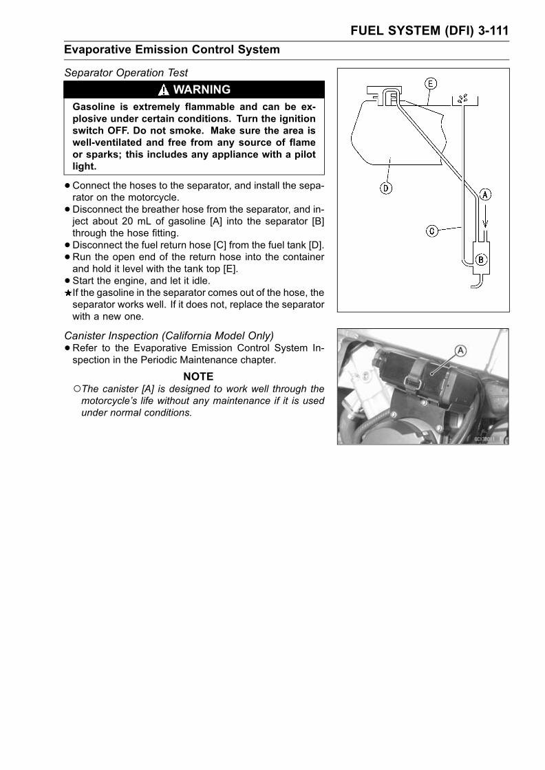
FUEL SYSTEM (DFI) 3-111
Evaporative Emission Control System
Separator Operation Test
WARNINGGasoline is extremely flammable and can be ex-plosive under certain conditions. Turn the ignitionswitch OFF. Do not smoke. Make sure the area iswell-ventilated and free from any source of flameor sparks; this includes any appliance with a pilotlight.
•Connect the hoses to the separator, and install the sepa-rator on the motorcycle.
•Disconnect the breather hose from the separator, and in-ject about 20 mL of gasoline [A] into the separator [B]through the hose fitting.
•Disconnect the fuel return hose [C] from the fuel tank [D].•Run the open end of the return hose into the containerand hold it level with the tank top [E].
• Start the engine, and let it idle.If the gasoline in the separator comes out of the hose, theseparator works well. If it does not, replace the separatorwith a new one.
Canister Inspection (California Model Only)
•Refer to the Evaporative Emission Control System In-spection in the Periodic Maintenance chapter.
NOTEThe canister [A] is designed to work well through themotorcycle’s life without any maintenance if it is usedunder normal conditions.


COOLING SYSTEM 4-1
4
Cooling System
Table of Contents
Exploded View........................................................................................................................ 4-2Specifications ......................................................................................................................... 4-4Special Tool ............................................................................................................................ 4-5Coolant Flow Chart................................................................................................................. 4-6Coolant ................................................................................................................................... 4-8
Coolant Deterioration Inspection....................................................................................... 4-8Coolant Level Inspection................................................................................................... 4-8Coolant Draining ............................................................................................................... 4-8Coolant Filling ................................................................................................................... 4-8Pressure Testing ............................................................................................................... 4-9Cooling System Flushing .................................................................................................. 4-9Coolant Filter Cleaning ..................................................................................................... 4-9Coolant Reserve Tank Removal ....................................................................................... 4-10Coolant Reserve Tank Installation .................................................................................... 4-10
Water Pump............................................................................................................................ 4-11Water Pump Removal ....................................................................................................... 4-11Water Pump Installation.................................................................................................... 4-11Water Pump Impeller Disassembly/Assembly .................................................................. 4-11Water Pump Inspection..................................................................................................... 4-11Water Pump Housing Disassembly .................................................................................. 4-11Water Pump Housing Assembly ....................................................................................... 4-12Mechanical Seal Inspection .............................................................................................. 4-12
Radiator, Radiator Fan ........................................................................................................... 4-13Radiator and Radiator Fan Removal ................................................................................ 4-13Radiator and Radiator Fan Installation ............................................................................. 4-14Radiator Inspection ........................................................................................................... 4-14Radiator Cap Inspection ................................................................................................... 4-14Radiator Filler Neck Inspection ......................................................................................... 4-15
Thermostat ............................................................................................................................. 4-16Thermostat Removal......................................................................................................... 4-16Thermostat Installation...................................................................................................... 4-16Thermostat Inspection ...................................................................................................... 4-16
Hose and Pipes ...................................................................................................................... 4-17Hose Installation ............................................................................................................... 4-17Hose Inspection ................................................................................................................ 4-17
Radiator Fan Switch, Water Temperature Sensor .................................................................. 4-18Radiator Fan Switch, Water Temperature Sensor Removal ............................................. 4-18Radiator Fan Switch, Water Temperature Sensor Installation .......................................... 4-18Radiator Fan Switch, Water Temperature Sensor Inspection ........................................... 4-18

4-2 COOLING SYSTEM
Exploded View

COOLING SYSTEM 4-3
Exploded View
TorqueNo. Fastener N·m kgf·m ft·lb Remarks
1 Water hose clamp screws 2.0 0.20 17 in·lb2 Coolant drain plug (water pump) 8.8 0.90 78 in·lb3 Coolant drain plug (cylinder) 8.8 0.90 78 in·lb4 Radiator fan switch 18 1.8 135 Water temperature sensor 25 2.5 18 SS6 Water pump impeller bolt 9.8 1.0 87 in·lb7 Water pump cover bolts 12 1.2 104 in·lb L8 Thermostat housing cover bolts 5.9 0.60 52 in·lb9 Coolant by-pass fitting 8.8 0.90 78 in·lb L10 Water hose fitting bolts 12 1.2 106 in·lb11 Radiator mounting bolts 6.9 0.70 61 in·lb12 Radiator bracket mounting bolts 6.9 0.70 61 in·lb13 Coolant reserve tank mounting screws 6.9 0.70 61 in·lb14 Oil cooler bolt 78 8.0 5815 Water passage plugs 20 2.0 14
L: Apply a non-permanent locking agent.EO: Apply engine oil.SS: Apply silicone sealant (Kawasaki Bond: 56019–120).

4-4 COOLING SYSTEM
Specifications
Item Standard
Coolant provided when shipping:
TypePermanent type of antifreeze (soft water and ethyleneglycol plus corrosion and rust inhibitor chemicals foraluminum engines and radiators)
Color Green
Mixed ratio Soft water 50%, coolant 50%
Freezing point -35°C (-31°F)
Total amount 2.4 L (2.5 US qt.) (reserve tank full level including
radiator and engine)
Radiator cap
Relief pressure: 93 ∼ 123 kPa (0.95 ∼ 1.25 kgf/cm², 14 ∼ 18 psi)Thermostat:
Valve opening temperature 58 ∼ 62°C (136 ∼ 144 °F)Valve full opening lift 8 mm (0.3 in.) or more @75°C (167 °F)
COOLING SYSTEM 4-5
Special Tool
Kawasaki Bond (Silicone Sealant) :56019–120

4-6 COOLING SYSTEM
Coolant Flow Chart
Permanent type antifreeze is used as a coolant to protect the cooling system from rust and corrosion.When the engine starts, the water pump turns and the coolant circulates.The thermostat is a wax pellet type which opens or closes with coolant temperature changes. The
thermostat continuously changes its valve opening to keep the coolant temperature at the proper level.When coolant temperature is below 58 ∼ 62°C (136 ∼ 144°F), the thermostat closes so that the coolantflow is restricted through the air bleeder hole, causing the engine to warm up more quickly. Whencoolant temperature is more than 58 ∼ 62°C (136 ∼ 144°F), the thermostat opens and the coolantflows.When the coolant temperature goes up beyond 92 ∼ 104°C (198 ∼ 219°F), the radiator fan switch
conducts to operate the radiator fan. The radiator fan draws air through the radiator core when thereis not sufficient air flow such as at low speeds. This increases up the cooling action of the radiator.When the temperature goes down from the operation temperature by 3 ∼ 8°C (37 ∼ 46°F), the fanswitch opens and the radiator fan stops.In this way, this system controls the engine temperature within narrow limits where the engine op-
erates most efficiently even if the engine load varies.The system is pressurized by the radiator cap to suppress boiling and the resultant air bubbles
which can cause engine overheating. As the engine warms up, the coolant in the radiator and thewater jacket expands. The excess coolant flows through the radiator cap and hose to the reserve tankto be stored there temporarily. Conversely, as the engine cools down, the coolant in the radiator andthe water jacket contracts, and the stored coolant flows back to the radiator from the reserve tank.The radiator cap has two valves. One is a pressure valve which holds the pressure in the system
when the engine is running. When the pressure exceeds 93 ∼ 123 kPa (0.95 ∼ 1.25 kgf/cm², 14 ∼ 18psi), the pressure valve opens and releases the pressure to the reserve tank. As soon as pressureescapes, the valve closes, and keeps the pressure at 93 ∼ 123 kPa (0.95 ∼ 1.25 kgf/cm², 14 ∼ 18 psi).When the engine cools down, another small valve (vacuum valve) in the cap opens. As the coolantcools, the coolant contracts to form a vacuum in the system. The vacuum valve opens and allows thecoolant from the reserve tank to enter the radiator.

COOLING SYSTEM 4-7
Coolant Flow Chart
1. Radiator2. Radiator Cap3. Radiator Fan4. Fan Switch
5. Drain Plugs6. Water Pump7. Water Temperature Sensor8. Oil Cooler
9. ThermostatWhen the engine is cold, the thermostat is closed so that the coolant flow is restricted throughthe air bleeder hole, causing the engine to warm up more quickly.
10. By-pass FittingThe fitting is installed to bleed the air.
11. Reserver TankWhen the engine is very hot, the pressure valve in the radiator cap allows air and vapor toescape into the reserve tank. When the engine cools down, the pressure drop draws the vacuumvalve (another small valve) open, admitting coolant from the reserve tank into the radiator.

4-8 COOLING SYSTEM
Coolant
Coolant Deterioration Inspection
•Visually inspect the coolant in the reserve tank.If whitish cotton-like wafts are observed, aluminum partsin the cooling system are corroded. If the coolant isbrown, iron or steel parts are rusting. In either case, flushthe cooling system.If the coolant gives off an abnormal smell, check for acooling system leak. It may be caused by exhaust gasleaking into the cooling system.
Coolant Level Inspection
NOTECheck the level when the engine is cold (room or ambi-ent temperature).
•Check the coolant level in the reserve tank with the mo-torcycle held perpendicular.If the coolant level is lower than the low level line [A], addcoolant to the full level line [B].
CAUTION
For refilling, add the specified mixture of coolantand soft water. Adding water alone dilutes thecoolant and degrades its anticorrosion properties.The diluted coolant can attack the aluminum en-gine parts. In an emergency, soft water alone canbe added. But the diluted coolant must be returnedto the correct mixture ratio within a few days.If coolant must be added often, or the reservoir tankhas run completely dry, there is probably leakage inthe cooling system. Check the system for leaks.
Coolant Draining
•Refer to the Cooling System in the Periodic Maintenancechapter.
Coolant Filling
•Refer to the Cooling System in the Periodic Maintenancechapter.

COOLING SYSTEM 4-9
Coolant
Pressure Testing
•Remove:Right Inner Cover (see Frame chapter)
•Remove the radiator cap, and install a cooling systempressure tester [A] on the filler neck.
NOTEWet the cap sealing surfaces with water or coolant toprevent pressure leaks.
•Build up pressure in the system carefully until the pres-sure reaches 123 kPa (1.25 kgf/cm², 18 psi).
CAUTION
During pressure testing, do not exceed the pres-sure for which the system is designed. The maxi-mum pressure is 123 kPa (1.25 kgf/cm², 18 psi).
•Watch the gauge for at least 6 seconds.If the pressure holds steady, the system is all right.If the pressure drops and no external source is found,check for internal leaks. Droplets in the engine oil indicateinternal leakage. Check the cylinder head gasket and thewater pump.
•Remove the pressure tester, replenish the coolant, andinstall the radiator cap.
Cooling System FlushingOver a period of time, the cooling system accumulates
rust, scale, and lime in the water jacket and radiator. Whenthis accumulation is suspected or observed, flush the cool-ing system. If this accumulation is not removed, it will clogup the water passage and considerable reduce the effi-ciency of the cooling system.
•Drain the cooling system (see Cooling System in the Pe-riodic Maintenance chapter).
• Fill the cooling system with fresh water mixed with a flush-ing compound.
CAUTION
Donot use a flushing compoundwhich is harmful tothe aluminum engine and radiator. Carefully followthe instructions supplied by themanufacturer of thecleaning product.
•Warm up the engine, and run it at normal operating tem-perature for about ten minutes.
• Stop the engine, and drain the cooling system.• Fill the system with fresh water.
•Warm up the engine and drain the system.
•Repeat the previous two steps once more.• Fill the system with a permanent type coolant and bleedthe air from the system (see Cooling System in the Peri-odic Maintenance chapter).
Coolant Filter Cleaning
•Refer to the Fuel System in the Periodic Maintenancechapter.

4-10 COOLING SYSTEM
Coolant
Coolant Reserve Tank Removal
•Remove:Coolant Reserve Tank Mounting Screws [A]
•Remove:Coolant Reserve Tank Mounting Screws [A]CollarIdle Adjuster Bracket [B]Coolant Reserve Tank [C]
Coolant Reserve Tank Installation
• Install:Coolant Reserve Tank [A]Collar [B]Idle Adjuster Bracket [C]
• Tighten:Torque - Coolant Reserve Tank Mounting Screws [D]: 6.9
N·m (0.70 kgf·m, 61 in·lb)
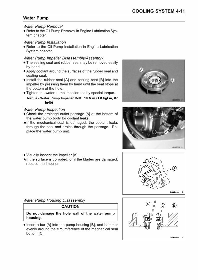
COOLING SYSTEM 4-11
Water Pump
Water Pump Removal
•Refer to the Oil Pump Removal in Engine Lubrication Sys-tem chapter.
Water Pump Installation
•Refer to the Oil Pump Installation in Engine LubricationSystem chapter.
Water Pump Impeller Disassembly/Assembly
•The sealing seat and rubber seal may be removed easilyby hand.
• Apply coolant around the surfaces of the rubber seal andsealing seat.
• Install the rubber seal [A] and sealing seat [B] into theimpeller by pressing them by hand until the seat stops atthe bottom of the hole.
• Tighten the water pump impeller bolt by special torque.Torque - Water Pump Impeller Bolt: 10 N·m (1.0 kgf·m, 87
in·lb)
Water Pump Inspection
•Check the drainage outlet passage [A] at the bottom ofthe water pump body for coolant leaks.If the mechanical seal is damaged, the coolant leaksthrough the seal and drains through the passage. Re-place the water pump unit.
• Visually inspect the impeller [A].If the surface is corroded, or if the blades are damaged,replace the impeller.
Water Pump Housing Disassembly
CAUTION
Do not damage the hole wall of the water pumphousing.
• Insert a bar [A] into the pump housing [B], and hammerevenly around the circumference of the mechanical sealbottom [C].

4-12 COOLING SYSTEM
Water Pump
•Take the oil seal [A] out of the housing [B] with a hook [C].
Water Pump Housing Assembly
CAUTION
Do not reuse the mechanical seal and oil seal.
•Apply high temperature grease to the oil seal lips [A].• Press the new oil seal into the housing with a bearingdriver [B] until it stops at the bottom surface [C] of thehousing.
Special Tool - Bearing Driver Set: 57001-1129
CAUTION
Be careful not to damage the sealing surface of themechanical seal.
•Press the new mechanical seal into the housing with stembearing driver [A] until its flange [B] touches the surface[C] of the housing.
Special Tool - Bearing Driver: 57001–382
Mechanical Seal Inspection
•Visually inspect the mechanical seal.If any one of the parts is damaged, replace the mechani-cal seal as a unit.[A] Impeller Sealing Seat Surface[B] Rubber Seal[C] Mechanical Seal

COOLING SYSTEM 4-13
Radiator, Radiator Fan
Radiator and Radiator Fan Removal
WARNINGThe radiator fan is connected directly to the bat-tery. The radiator fan may start even if the ignitionswitch is off. NEVER TOUCH THE RADIATOR FANUNTIL THE RADIATOR FAN CONNECTOR IS DIS-CONNECTED. TOUCHING THE FAN BEFORE THECONNECTOR IS DISCONNECTED COULD CAUSEINJURY FROM THE FAN BLADES.
•Remove:Lower Fairings (see Frame chapter)Coolant (see Cooling System in the Periodic Mainte-nance chapter)Radiator Hoses [A]Radiator Mounting Bolt [B]
•Remove:Fan Switch Lead Connector [A]Radiator Hose [B]
•Remove:Radiator Mounting Bolts [A]Radiator Fan Lead ConnectorRadiator [B]
•Remove:Radiator Fan Mounting Bolts [A]Radiator Fan [B]
CAUTION
Do not touch the radiator core. This could damagethe radiator fins, resulting in loss of cooling effi-ciency.

4-14 COOLING SYSTEM
Radiator, Radiator Fan
Radiator and Radiator Fan Installation
• Install:Radiator [A]Dampers [B] (note the direction)Collars [C]Horn [D]Bracket [E]
• Tighten:Torque - Radiator Bracket Mounting Bolts (L= 16 mm) [F]:
6.9 N·m (0.70 kgf·m, 61 in·lb)Radiator Mounting Bolts (L= 30 mm) [G]: 6.9 N·m(0.70 kgf·m, 61 in·lb)
Radiator Mounting Bolts (L= 25 mm) [H]: 6.9 N·m(0.70 kgf·m, 61 in·lb)
Radiator Inspection
•Check the radiator core.If there are obstructions to air flow, remove them.If the corrugated fins [A] are deformed, carefullystraighten them.If the air passages of the radiator core are blocked morethan 20% by unremovable obstructions or irreparably de-formed fins, replace the radiator with a new one.
CAUTION
When cleaning the radiator with steam cleaner, becareful of the following to prevent radiator damage.Keep the steam gun [A] away more than 0.5 m (1.6ft) [B] from the radiator core.Hold the steam gun perpendicular [C] (not oblique[D]) to the core surface.Run the steam gun following the core fin direction.
Radiator Cap Inspection
•Check the condition of the bottom [A] and top [B] valveseals and valve spring [C].If any one of them shows visible damage, replace the capwith a new one.
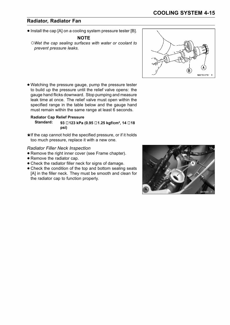
COOLING SYSTEM 4-15
Radiator, Radiator Fan
• Install the cap [A] on a cooling system pressure tester [B].NOTE
Wet the cap sealing surfaces with water or coolant toprevent pressure leaks.
•Watching the pressure gauge, pump the pressure testerto build up the pressure until the relief valve opens: thegauge hand flicks downward. Stop pumping andmeasureleak time at once. The relief valve must open within thespecified range in the table below and the gauge handmust remain within the same range at least 6 seconds.
Radiator Cap Relief PressureStandard: 93 ∼ 123 kPa (0.95 ∼ 1.25 kgf/cm², 14 ∼ 18
psi)
If the cap cannot hold the specified pressure, or if it holdstoo much pressure, replace it with a new one.
Radiator Filler Neck Inspection
•Remove the right inner cover (see Frame chapter).• Remove the radiator cap.•Check the radiator filler neck for signs of damage.•Check the condition of the top and bottom sealing seats[A] in the filler neck. They must be smooth and clean forthe radiator cap to function properly.

4-16 COOLING SYSTEM
Thermostat
Thermostat Removal
•Remove:Coolant (see Cooling System in the Periodic Maintenancechapter)
Seats (see Frame chapter)Fuel Tank (see Fuel System chapter)Thermostat Housing Cover Bolts [A]Bracket [B]Thermostat Housing Cover [C]Thermostat
Thermostat Installation
•Be sure to install the O-ring [A] on the housing cover.• Tighten the housing cover bolts.Torque - Thermostat Housing Cover Bolts: 5.9 N·m (0.60
kgf·m, 52 in·lb)
•Fill the radiator with coolant.
Thermostat Inspection
•Remove the thermostat, and inspect the thermostat valve[A] at room temperature.If the valve is open, replace the thermostat with a newone.
• To check valve opening temperature, suspend the ther-mostat [A] in a container of water and raise the tempera-ture of the water.The thermostat must be completely submerged and mustnot touch the container sides or bottom. Suspend an ac-curate thermometer [B] in the water so that the heat sen-sitive portions [C] are located in almost the same depth.It must not touch the container, either.If the measurement is out of the specified range, replacethe thermostat with a new one.
Thermostat Valve Opening Temperature58 ∼ 62°C (136 ∼ 144°F)

COOLING SYSTEM 4-17
Hose and Pipes
Hose Installation
• Install the hoses and pipes being careful to follow bend-ing direction or diameter. Avoid sharp bending, kinking,flattening, or twisting.
• Install the clamps [A] as near as possible to the hose endto clear the raised rib or the fitting. This will prevent thehoses from working loose.The clamp screws should be positioned correctly to pre-vent the clamps from contacting anything.
Torque - Hose Clamp Screws: 2.0 N·m (0.20 kgf·m, 17 in·lb)
Hose InspectionRefer to the Cooling System in the Periodic Maintenancechapter

4-18 COOLING SYSTEM
Radiator Fan Switch, Water Temperature Sensor
Radiator Fan Switch, Water Temperature SensorRemoval
CAUTION
The fan switch or the water temperature sensorshould never be allowed to fall on a hard surface.Such a shock to their parts can damage them.
•Drain the coolant (see Cooling System in the PeriodicMaintenance chapter).
• Remove:Radiator Fan Switch Lead Connector [A]Radiator Fan Switch [B]
•Remove:Seats (see Frame chapter)Fuel Tank (see Fuel System chapter)Water Temperature Sensor Lead Connector [A]Water Temperature Sensor [B]
Radiator Fan Switch, Water Temperature SensorInstallation
•Apply silicone sealant to the threads of the water temper-ature sensor.
Sealant - Kawasaki Bond (Silicone Sealant): 56019-120
•Tighten the fan switch and water temperature sensor.Torque - Radiator Fan Switch : 18 N·m (1.8 kgf·m, 13 ft·lb)
Water Temperature Sensor : 25 N·m (2.5 kgf·m, 18ft·lb)
•Fill the coolant and bleed the air from cooling system (seeCooling System in the Periodic Maintenance chapter).
Radiator Fan Switch, Water Temperature SensorInspection
•Refer to the Electrical System chapter for these inspec-tions.
ENGINE TOP END 5-1
5
Engine Top End
Table of Contents
Exploded View................................... 5-2Specifications .................................... 5-6Special Tools and Sealant ................. 5-8Clean Air System............................... 5-10
Air Suction Valve Removal........... 5-10Air Suction Valve Installation........ 5-10Air Suction Valve Inspection ........ 5-10Vacuum Switch Valve Removal ... 5-10Vacuum Switch Valve Installation 5-10Vacuum Switch Valve Test ........... 5-11Clean Air System HoseInspection.................................. 5-11
Cylinder Head Cover ......................... 5-12Cylinder Head Cover Removal .... 5-12Cylinder Head Cover Installation . 5-12
Camshaft Chain Tensioner ................ 5-14Camshaft Chain TensionerRemoval .................................... 5-14
Camshaft Chain TensionerInstallation ................................. 5-14
Camshaft, Camshaft Chain ............... 5-15Camshaft Removal ...................... 5-15Camshaft Installation ................... 5-15Camshaft, Camshaft Cap Wear ... 5-17Camshaft Runout ......................... 5-17Cam Wear.................................... 5-17Camshaft Chain Removal ............ 5-18Camshaft and SprocketAssembly................................... 5-18
Cylinder Head.................................... 5-19Cylinder CompressionMeasurement ............................ 5-19
Cylinder Head Removal ............... 5-20Cylinder Head Installation ............ 5-21
Cylinder Head Warp..................... 5-21Valves ................................................ 5-22
Valve Clearance Inspection ......... 5-22Valve Clearance Adjustment........ 5-22Valve Removal ............................. 5-22Valve Installation .......................... 5-22Valve Guide Removal .................. 5-22Valve Guide Installation ............... 5-23Valve-to-Guide ClearanceMeasurement (WobbleMethod) ..................................... 5-23
Valve Seat Inspection .................. 5-24Valve Seat Repair ........................ 5-24
Cylinder, Pistons................................ 5-29Cylinder Removal......................... 5-29Cylinder Installation...................... 5-29Piston Removal............................ 5-29Piston Installation......................... 5-30Cylinder Wear .............................. 5-31Piston Wear ................................. 5-31Piston Ring, Piston Ring GrooveWear.......................................... 5-32
Piston Ring Groove Width............ 5-32Piston Ring Thickness ................. 5-33Piston Ring End Gap ................... 5-33
Throttle Valve Holder ......................... 5-34Throttle Valve Holder Installation . 5-34
Muffler................................................ 5-35Exhaust Pipe Manifold Removal .. 5-35Exhaust Pipe ManifoldInstallation ................................. 5-35
Muffler Body Removal.................. 5-35Muffler Body Installation............... 5-35

5-2 ENGINE TOP END
Exploded View

ENGINE TOP END 5-3
Exploded View
TorqueNo. Fastener N·m kgf·m ft·lb Remarks
1 Air suction valve cover bolts 12 1.2 104 in·lb L
2 Cylinder head cover bolts 9.8 1.0 87 in·lb
3 Spark plugs 13 1.3 113 in·lb
4 Camshaft cap bolts 12 1.2 104 in·lb S
5 Cylinder head bolts (9 mm) 40 4.1 30
6 Cylinder head bolts (6 mm) 12 1.2 104 in·lb S
7 Cylinder head jacket plug (upper) 20 2.0 14.5 L
8 Cylinder head jacket plug (left) 20 2.0 14.5 L
9 Coolant by-pass fitting 8.8 0.90 78 in·lb L
10 Water temperature sensor 25 2.5 18 SS
11 Camshaft position sensor bolt 12 1.2 104 in·lb
12 Throttle body assembly holder bolts 12 1.2 104 in·lb
13Throttle body assembly holder clampbolts
2.5 0.25 22 in·lb
14 Camshaft sprocket bolts 15 1.5 11 L
15 Front camshaft chain guide bolt (upper) 25 2.5 18
16 Front camshaft chain guide bolt (lower) 12 1.2 104 in·lb
17 Rear camshaft chain guide bolt 25 2.5 18
18Camshaft chain tensioner mountingbolts
9.8 1.0 87 in·lb
19 Camshaft chain tensioner cap bolt 29 3.0 21
20. Closed coil end faces downward.G: Apply grease.L: Apply a non-permanent locking agent.M: Apply molybdenum disulfide grease.EO: Apply engine oil.SS: Apply silicone sealant.R: Replacement PartsS: Follow the specific tightening sequence.

5-4 ENGINE TOP END
Exploded View
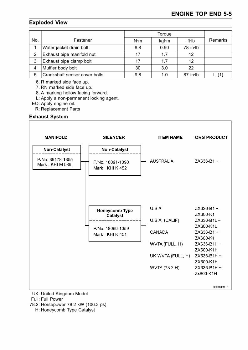
ENGINE TOP END 5-5
Exploded View
TorqueNo. Fastener N·m kgf·m ft·lb Remarks
1 Water jacket drain bolt 8.8 0.90 78 in·lb
2 Exhaust pipe manifold nut 17 1.7 12
3 Exhaust pipe clamp bolt 17 1.7 12
4 Muffler body bolt 30 3.0 22
5 Crankshaft sensor cover bolts 9.8 1.0 87 in·lb L (1)
6. R marked side face up.7. RN marked side face up.8. A marking hollow facing forward.L: Apply a non-permanent locking agent.
EO: Apply engine oil.R: Replacement Parts
Exhaust System
UK: United Kingdom ModelFull: Full Power78.2: Horsepower 78.2 kW (106.3 ps)H: Honeycomb Type Catalyst

5-6 ENGINE TOP END
Specifications
Item Standard Service Limit
Clean Air System:
Vacuum switch valve closingpressure:
Open → Close41 ∼ 49 kPa (310 ∼ 370 mmHg)
Camshafts
Cam height:
Exhaust 33.146 ∼ 33.254 mm (1.305 ∼ 1.309 in.) 33.05 mm (1.30 in.)
Inlet 34.146 ∼ 34.254 mm (1.344 ∼ 1.349 in.) 34.05 mm (1.34 in.)
Camshaft journal, camshaftcap clearance
0.038 ∼ 0.081 mm (0.001 ∼ 0.003 in.) 0.17 mm (0.007 in.)
Camshaft journal diameter23.940 ∼ 23.962 mm(0.9425 ∼ 0.9434 in.) 23.91 mm (0.941 in.)
Camshaft bearing insidediameter
24.000 ∼ 24.021 mm(0.9449 ∼ 0.9457 in.) 24.08 mm (0.948 in.)
Camshaft runout TIR 0.02 mm (0.0008 in.) or less TIR 0.1 mm (0.004 in.)
Cylinder Head:
Cylinder compression (usable range)
950 ∼ 1 450 kPa (9.7 ∼ 14.8 kgf/cm²,138 ∼ 210 psi) @350 r/min (rpm) – – –
Cylinder head warp – – – 0.05 mm (0.002 in.)
Valves:
Valve head thickness:
Exhaust 1.0 mm (0.04 in.) 0.6 mm (0.02 in.)
Inlet 0.5 mm (0.02 in.) 0.25 mm (0.01 in.)
Valve stem bend TIR 0.01 mm (0.0004 in.) or less TIR 0.05 mm (0.002 in.)
Valve stem diameter:
Exhaust 3.955 ∼ 3.970 mm (0.1557 ∼ 0.1563 in.) 3.94 mm (0.155 in.)
Inlet 3.975 ∼ 3.990 mm (0.1565 ∼ 0.1571 in.) 3.96 mm (0.156 in.)
Valve guide inside diameter
Exhaust 4.000 ∼ 4.012 mm (0.1575 ∼ 0.1580 in.) 4.08 mm (0.161 in.)
Inlet 4.000 ∼ 4.012 mm (0.1575 ∼ 0.1580 in.) 4.08 mm (0.161 in.)
Valve/valve guide clearance(wobble method):
Exhaust 0.10 ∼ 0.18 mm (0.0039 ∼ 0.0071 in.) 0.35 mm (0.014 in.)
Inlet 0.03 ∼ 0.12 mm (0.0012 ∼ 0.0047 in.) 0.29 mm (0.011 in.)
Valve seat cutting angle 45°, 32°, 60° – – –
Valve seat surface:
Width: Exhaust 0.5 ∼ 1.0 mm (0.02 ∼ 0.04 in.) – – –
Inlet 0.5 ∼ 1.0 mm (0.02 ∼ 0.04 in.) – – –
Outside diameter:
Exhaust 22.1 ∼ 22.3 mm (0.87 ∼ 0.88 in.) – – –
Inlet 26.4 ∼ 26.6 mm (1.04 ∼ 1.05 in.) – – –
Valve spring free length:
Exhaust 39.4 mm (1.55 in.) 38.0 mm (1.50 in.)
Inlet 35.3 mm (1.39 in.) 33.9 mm (1.33 in.)

ENGINE TOP END 5-7
Specifications
Item Standard Service Limit
Cylinder, Piston:
Cylinder inside diameter
ZX636 68.000 ∼ 68.012 mm (2.677 ∼ 2.678 in.) 68.10 mm (2.68 in.)
ZX600 67.000 ∼ 67.012 mm (2.637 ∼ 2.638 in.) 67.10 mm (2.64 in.)
Piston diameter ZX636 67.975∼ 67.990 mm (2.676 ∼ 2.677 in.) 67.83 mm (2.67 in.)
ZX600 66.975∼ 66.990 mm (2.636 ∼ 2.637 in.) 66.83 mm (2.63 in.)
Piston/cylinder clearance: 0.010 ∼ 0.037 mm (0.0004 ∼ 0.0015 in.) – – –
Piston ring/groove clearance
Top ZX636 0.03 ∼ 0.05 mm (0.0012 ∼ 0.0020 in.) 0.15 mm (0.0059 in.)
ZX600 0.05 ∼ 0.09 mm (0.0020 ∼ 0.0035 in.) 0.19 mm (0.0075 in.)
Second 0.03 ∼ 0.07 mm (0.0012 ∼ 0.0028 in.) 0.17 mm (0.0067 in.)
Piston ring groove width:
Top ZX636 0.82 ∼ 0.84 mm (0.0322 ∼ 0.0331 in.) 0.92 mm (0.036 in.)
ZX600 0.84 ∼ 0.86 mm (0.0331 ∼ 0.0339 in.) 0.94 mm (0.037 in.)
Second 0.82 ∼ 0.84 mm (0.0323 ∼ 0.0331 in.) 0.92 mm (0.036 in.)
Piston ring thickness:
Top 0.77 ∼ 0.79 mm (0.0303 ∼ 0.0311 in.) 0.70 mm (0.028 in.)
Second 0.77 ∼ 0.79 mm (0.0303 ∼ 0.0311 in.) 0.70 mm (0.028 in.)
Piston ring end gap:
Top 0.12 ∼ 0.22 mm (0.0047 ∼ 0.0087 in.) 0.5 mm (0.020 in.)
Second 0.30 ∼ 0.45 mm (0.0118 ∼ 0.0177 in.) 0.8 mm (0.031 in.)

5-8 ENGINE TOP END
Special Tools and Sealant
Compression Gauge:57001–221
Valve Spring Compressor Assembly:57001–241
Piston Pin Puller Assembly:57001–910
Valve Seat Cutter, 45° – 24.5:57001–1113
Valve Seat Cutter, 45° – 27.5:57001–1114
Valve Seat Cutter, 32° – 25:57001–1118
Valve Seat Cutter, 32° – 28:57001–1119
Valve Seat Cutter Holder Bar:57001–1128
Valve Spring Compressor Adapter, 21:57001–1272
Spark Plug Wrench, Hex 16:57001–1262
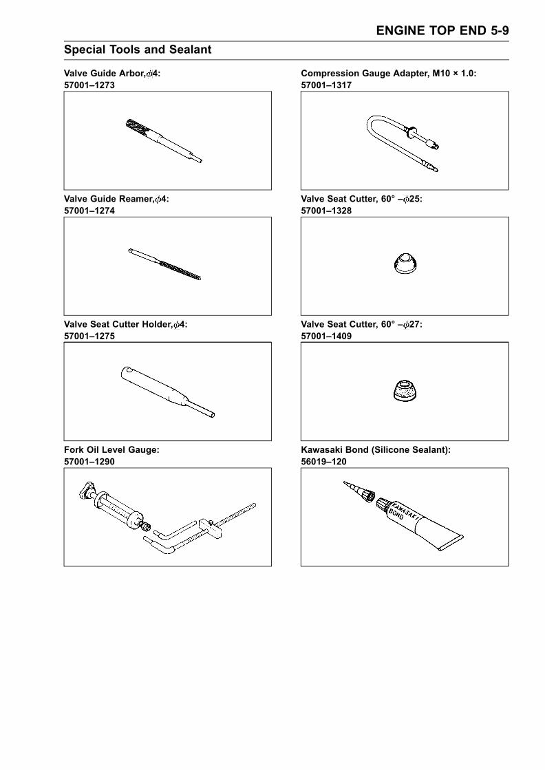
ENGINE TOP END 5-9
Special Tools and Sealant
Valve Guide Arbor, 4:57001–1273
Valve Guide Reamer, 4:57001–1274
Valve Seat Cutter Holder, 4:57001–1275
Fork Oil Level Gauge:57001–1290
Compression Gauge Adapter, M10 × 1.0:57001–1317
Valve Seat Cutter, 60° – 25:57001–1328
Valve Seat Cutter, 60° – 27:57001–1409
Kawasaki Bond (Silicone Sealant):56019–120
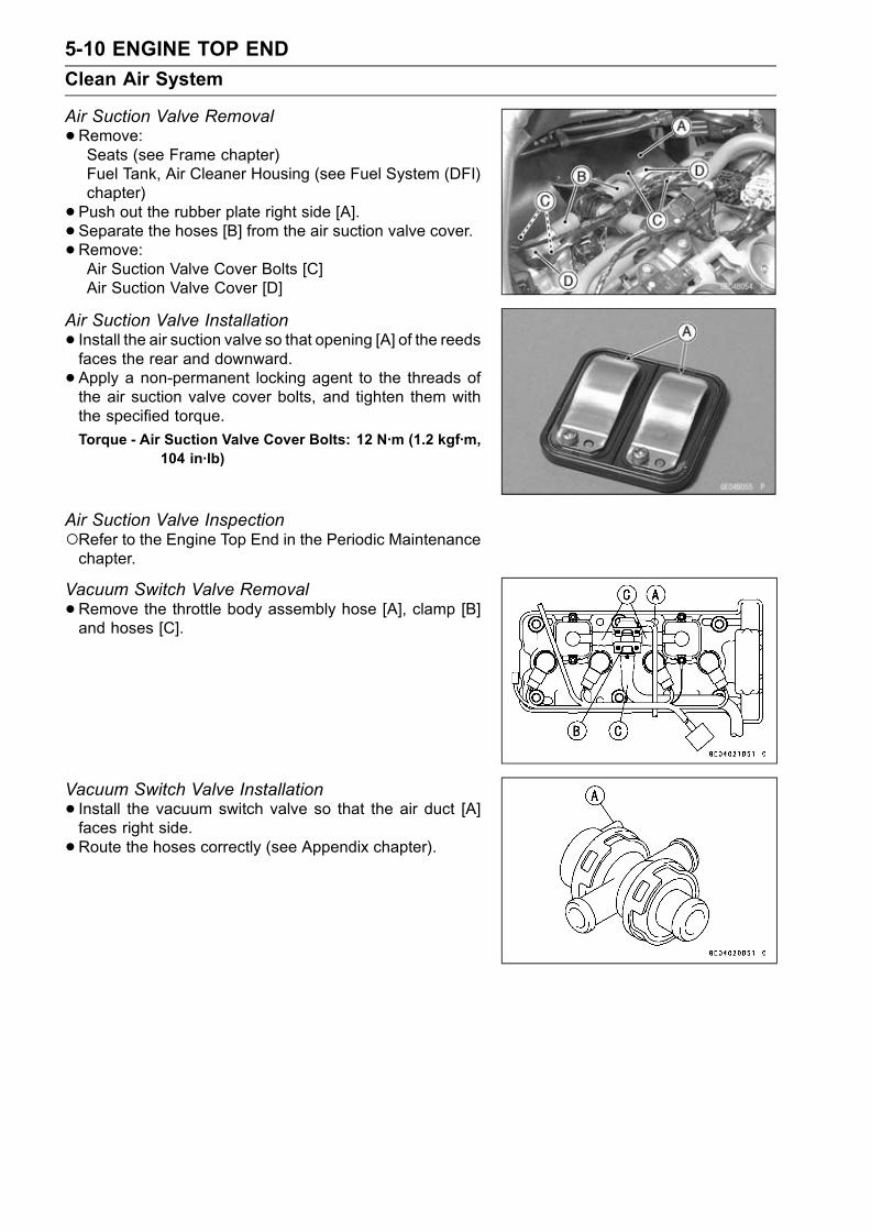
5-10 ENGINE TOP END
Clean Air System
Air Suction Valve Removal
•Remove:Seats (see Frame chapter)Fuel Tank, Air Cleaner Housing (see Fuel System (DFI)chapter)
• Push out the rubber plate right side [A].• Separate the hoses [B] from the air suction valve cover.•Remove:Air Suction Valve Cover Bolts [C]Air Suction Valve Cover [D]
Air Suction Valve Installation
• Install the air suction valve so that opening [A] of the reedsfaces the rear and downward.
• Apply a non-permanent locking agent to the threads ofthe air suction valve cover bolts, and tighten them withthe specified torque.
Torque - Air Suction Valve Cover Bolts: 12 N·m (1.2 kgf·m,104 in·lb)
Air Suction Valve InspectionRefer to the Engine Top End in the Periodic Maintenancechapter.
Vacuum Switch Valve Removal
•Remove the throttle body assembly hose [A], clamp [B]and hoses [C].
Vacuum Switch Valve Installation
• Install the vacuum switch valve so that the air duct [A]faces right side.
•Route the hoses correctly (see Appendix chapter).

ENGINE TOP END 5-11
Clean Air System
Vacuum Switch Valve Test
•Remove:Fuel Tank, Air Cleaner Housing (see Fuel System (DFI)chapter)Vacuum Switch Valve
•Connect a vacuum gauge [A] and syringe [B] or fork oillevel gauge to the vacuum hoses as shown.
Special Tool - Fork Oil Level Gauge: 57001-1290
Air Flow [C]
•Gradually raise the vacuum (lower the pressure) appliedto the vacuum switch valve, and check the valve opera-tion. When the vacuum is low, the vacuum switch valveshould permit air to flow. When the vacuum raises tovalve closing pressure, it should stop air flow.Spring [A]Diaphragm [B]Valve [C]Low Vacuum [D]Secondary Air Flow [E]
If the vacuum switch valve does not operate as described,replace it with a new one.
NOTETo check air flow through the vacuum switch valve, justblow through the air cleaner hose.
Vacuum Switch Valve Closing Pressure (Open→ Close)Standard: 41 ∼ 49 kPa (310 ∼ 370 mmHg)
High Vacuum [A]Secondary air cannot flow [B]
Clean Air System Hose Inspection
•Be certain that all the hoses are routed without being flat-tened or kinked, and are connected correctly to the aircleaner housing, vacuum switch valve, #2 and #3 throttlebody and air suction valve covers.If they are not, correct them. Replace them if they aredamaged.

5-12 ENGINE TOP END
Cylinder Head Cover
Cylinder Head Cover Removal
•Remove:Lower Fairing (see Frame chapter)Seats (see Frame chapter)Fuel Tank, Air Cleaner Housing and Throttle Body As-sembly (see Fuel System (DFI) chapter)Vacuum Switch Valve [A] and Hoses [B]
•Remove:Air suction valve cover boltsAir suction valve
•Push out the rubber plate right side [A].•Remove the stick coils [B].
• Remove the main harness clamp [A].•Remove the cylinder head cover bolts [B].
• Remove the cylinder head cover [A] to backward [B] float-ing it a little up.
Cylinder Head Cover Installation
•Replace the head cover gasket with a new one if dam-aged.
• Apply silicone sealant to the cylinder head as shown [A].Sealant - Kawasaki Bond (Silicone Sealant): 56019-120

ENGINE TOP END 5-13
Cylinder Head Cover
•Be sure to install the pins [A] and rubber gaskets [B].
• Install the chain guide [A].• Install the washer [B] with the metal side faces upward.• Tighten:Torque - Cylinder Head Cover Bolts: 9.8 N·m (1.0 kgf·m, 87
in·lb) [C]
• Install the rubber plate so that left side [A] of it into be-tween radiator fan and cylinder head cover, and light side[B] of it onto the cylinder head cover.
•Route the radiator fan harness, fan switch lead wire andcamshaft position sensor lead wire in accordance withHarness Routing section in Appendix chapter.
• Install the air suction valve and air suction valve covers.NOTE
Do not forget to install the engine ground lead on theback side bolt of right side air suction valve cover.
Torque - Air Suction Valve Cover Bolts: 12 N·m (1.2 kgf·m,104 in·lb)
• Install:Stick CoilVacuum Switch Valve and HosesFuel Tank, Air Cleaner Housing and Throttle Body As-semblySeatsLower Fairing

5-14 ENGINE TOP END
Camshaft Chain Tensioner
Camshaft Chain Tensioner Removal
CAUTION
This is a non-return type camshaft chain tensioner.The push rod does not return to its original positiononce it moves out to take up camshaft chain slack.Observe all the rules listed below:When removing the tensioner, do not take out themounting bolts only halfway. Retightening themounting bolts from this position could damagethe tensioner and the camshaft chain. Once thebolts are loosened, the tensioner must be removedand reset as described in "Camshaft Chain Ten-sioner Installation."Do not turn over the crankshaft while the tensioneris removed. This could upset the camshaft chaintiming, and damage the valves.
•Remove:Seats (see Frame chapter)Fuel Tank (see Fuel System chapter)Cap Bolt [A]Washer [B]Spring [C]Rod [D]
•Remove the mounting bolts [E] and take off the camshaftchain tensioner.
Camshaft Chain Tensioner Installation
•Apply grease to the O-ring.•Release the stopper [A] and push the push rod [B] intothe tensioner body [C].Insert the push rod so that the push rod teeth are leavedsix notches.
• Install the tensioner body so that the stopper faces up-ward.
• Tighten:Torque - Camshaft Chain Tensioner Mounting Bolts [A]: 9.8
N·m (1.0 kgf·m, 87 in·lb)
• Install the rod, spring and washer.• Tighten:Torque - Camshaft Chain Tensioner Cap Bolt [B]: 29 N·m
(3.0 kgf·m, 21 ft·lb)
•Turn the crankshaft 2 turns clockwise to allow the ten-sioner to expand and recheck the camshaft chain timing.

ENGINE TOP END 5-15
Camshaft, Camshaft Chain
Camshaft Removal
•Remove:Cylinder Head Cover (see Cylinder HeadCover Removal)Pickup Coil Cover
• Position the crankshaft at #1, 4 piston TDC.[A] TDC mark for #1, 4 Pistons[B] Timing Mark (crankcase halves mating surface)
•Remove:Camshaft Chain Tensioner (see Camshaft Chain Ten-sioner Removal)
Rubber Gaskets and Cylinder Head Cover GasketCamshaft Cap BoltsCamshaft Cap [A]Camshafts [B]
• Stuff a clean cloth into the chain tunnel to keep any partsfrom dropping into the crankcase.
CAUTION
The crankshaft may be turned while the camshaftsare removed. Always pull the chain taut while turn-ing the crankshaft. This avoids kinking the chainon the lower (crankshaft) sprocket. A kinked chaincould damage both the chain and the sprocket.
Camshaft Installation
•Be sure to install the following parts.[A] O-rings[B] O-rings[C] Pins
•Assemble the camshaft (see Camshaft and Sprocket As-sembly).
• Apply engine oil to all cam parts and journals.
• If a new camshaft is to be used, apply a thin coat of molyb-denum disulfide grease to the cam surfaces.
NOTEThe exhaust camshaft has a 161 EX mark [A] and theinlet camshaft has a 161 IN mark [B]. Be careful not tomix up these shafts.

5-16 ENGINE TOP END
Camshaft, Camshaft Chain
•Position the crankshaft at #1, 4 piston TDC.•Pull the tension side (exhaust side) [A] of the chain tautto install the chain.
• Engage the camshaft chain with the camshaft sprocketsso that the timing marks on the sprockets are positionedas shown.The timing marks of #1, 4 must be aligned with the lowersurface of crankcase of rear side [E].
•Check to see the timing marks must be aligned with thecylinder head upper surface [B].[C] EX mark[D] IN mark
Confirmation of inlet camshaft sprocket position is usingmirror.
• Install the camshaft cap.First tighten the camshaft cap evenly to seat the camshaftin place, then tighten all bolts following the specified tight-ening sequence.
Torque - Camshaft Cap Bolts: 12 N·m (1.2 kgf·m, 104 in·lb)
•Tighten the camshaft chain tensioner (see CamshaftChain Tensioner Installation).
• Install the cylinder head cover (see Cylinder Head CoverInstallation).

ENGINE TOP END 5-17
Camshaft, Camshaft Chain
Camshaft, Camshaft Cap Wear
•Remove the camshaft cap (see Camshaft Removal).• Cut strips of plastigage to journal width. Place a stripon each journal parallel to the camshaft installed in thecorrect position.
•Measure each clearance between the camshaft journaland the camshaft cap using plastigage (press gauge) [A].
• Tighten:Torque - Camshaft Cap Bolts: 12 N·m (1.2 kgf·m, 104 in·lb)
NOTEDo not turn the camshaft when the plastigage is be-tween the journal and camshaft cap.
Camshaft Journal, Camshaft Cap ClearanceStandard: 0.038 ∼ 0.081 mm (0.001 ∼ 0.003 in.)Service Limit: 0.17 mm (0.007 in.)
If any clearance exceeds the service limit, measure thediameter of each camshaft journal with a micrometer.
Camshaft Journal DiameterStandard: 23.940 ∼ 23.962 mm (0.9425 ∼ 0.9434 in.)Service Limit: 23.91 mm (0.941 in.)
If the camshaft journal diameter is less than the servicelimit, replace the camshaft with a new one and measurethe clearance again.If the clearance still remains out of the limit, replace thecylinder head unit.
Camshaft Runout
•Remove the camshaft (see Camshaft Removal).• Set the camshaft in a camshaft alignment jig or on Vblocks.
•Measure runout with a dial gauge at the specified placeas shown.If the runout exceeds the service limit, replace the shaft.
Camshaft RunoutStandard: TIR 0.02 mm (0.00079 in.) or less
Service Limit: TIR 0.1 mm (0.004 in.)
Cam Wear
•Remove the camshaft (see Camshaft Removal).•Measure the height [A] of each cam with a micrometer.If the cams are worn down past the service limit, replacethe camshaft.
Cam Height
Standard Service Limit
Exhaust33.146 ∼ 33.254 mm(1.305 ∼ 1.309 in.)
33.05 mm(1.30 in.)
Inlet34.146 ∼ 34.254 mm(1.344 ∼ 1.349 in.)
34.05 mm(1.34 in.)

5-18 ENGINE TOP END
Camshaft, Camshaft Chain
Camshaft Chain Removal
•Split the crankcase (see Crankshaft/Transmission chap-ter).
• Remove the camshaft chain [A] from the crankshaftsprocket.
Camshaft and Sprocket Assembly
• Inlet and exhaust camshaft sprockets are the same.• Install the sprockets so that the marked side facesoutwards, and align the holes [A] on the camshaft andsprocket circular holes [B].
• Apply a non-permanent locking agent to the camshaftsprocket bolts and tighten them.
Torque - Camshaft Sprocket Bolts: 15 N·m (1.5 kgf·m, 11.0ft·lb)

ENGINE TOP END 5-19
Cylinder Head
Cylinder Compression Measurement
NOTEUse the battery which is fully charged.•Warm up the engine thoroughly.
• Stop the engine.•Remove:Seats (see Frame chapter)Fuel Tank (see Fuel System (DFI) chapter)Air Cleaner Housing (see Fuel System (DFI) chapter)Stick CoilsSpark Plugs
Special Tool - Spark Plug Wrench, Hex 16: 57001-1262
•Attach the compression gauge [A] and adapter [B] firmlyinto the spark plug hole.Using the startermotor, turn the engine over with the throt-tle fully open until the compression gauge stops rising; thecompression is the highest reading obtainable.
Special Tool - Compression Gauge: 57001-221Compression Gauge Adapter, M10 × 1.0:57001-1317
Cylinder Compression
Usable Range :950 ∼ 1 450 kPa (9.7 ∼ 14.8 kgf/cm², 138∼ 210 psi) @ 350 r/min (rpm)
•Repeat the measurement for the other cylinders.• Install the spark plugs.Torque - Spark Plugs: 13 N·m (1.3 kgf·m, 113 in·lb)
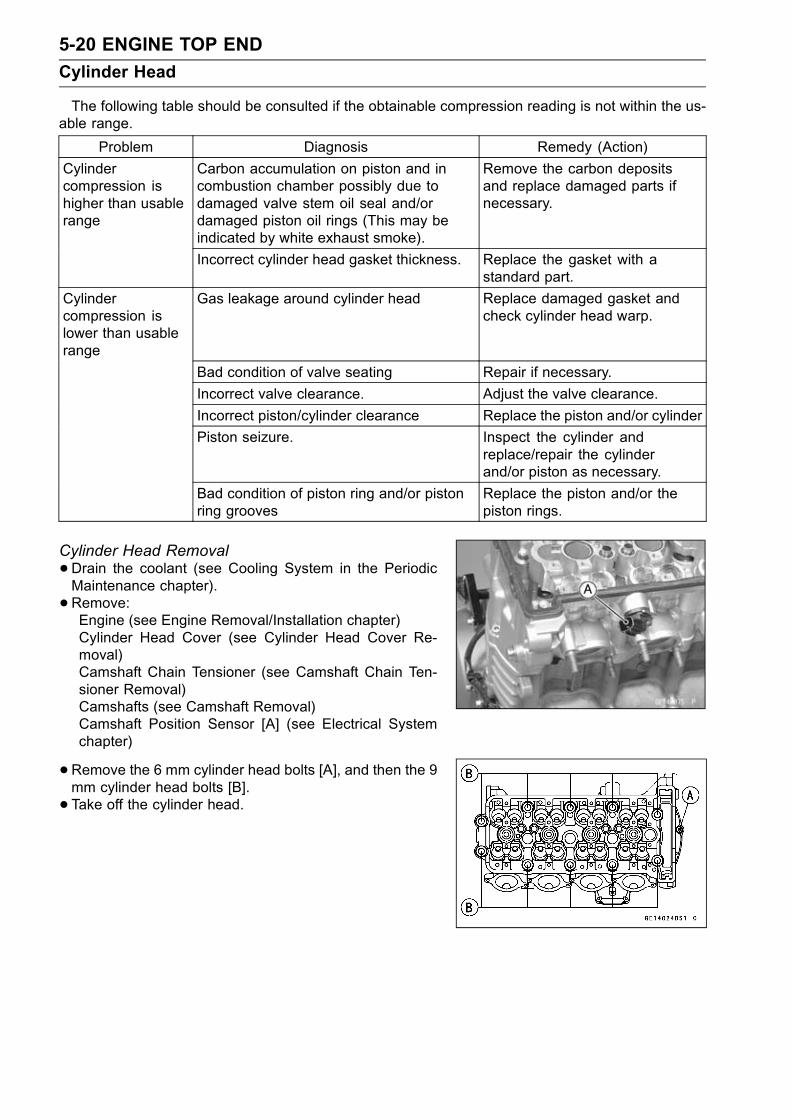
5-20 ENGINE TOP END
Cylinder Head
The following table should be consulted if the obtainable compression reading is not within the us-able range.
Problem Diagnosis Remedy (Action)
Cylindercompression ishigher than usablerange
Carbon accumulation on piston and incombustion chamber possibly due todamaged valve stem oil seal and/ordamaged piston oil rings (This may beindicated by white exhaust smoke).
Remove the carbon depositsand replace damaged parts ifnecessary.
Incorrect cylinder head gasket thickness. Replace the gasket with astandard part.
Cylindercompression islower than usablerange
Gas leakage around cylinder head Replace damaged gasket andcheck cylinder head warp.
Bad condition of valve seating Repair if necessary.
Incorrect valve clearance. Adjust the valve clearance.
Incorrect piston/cylinder clearance Replace the piston and/or cylinder
Piston seizure. Inspect the cylinder andreplace/repair the cylinderand/or piston as necessary.
Bad condition of piston ring and/or pistonring grooves
Replace the piston and/or thepiston rings.
Cylinder Head Removal
•Drain the coolant (see Cooling System in the PeriodicMaintenance chapter).
• Remove:Engine (see Engine Removal/Installation chapter)Cylinder Head Cover (see Cylinder Head Cover Re-moval)Camshaft Chain Tensioner (see Camshaft Chain Ten-sioner Removal)Camshafts (see Camshaft Removal)Camshaft Position Sensor [A] (see Electrical Systemchapter)
•Remove the 6 mm cylinder head bolts [A], and then the 9mm cylinder head bolts [B].
• Take off the cylinder head.

ENGINE TOP END 5-21
Cylinder Head
Cylinder Head Installation
NOTEThe camshaft cap is machined with the cylinder head,so if a new cylinder head is installed, use the cap thatis supplied with the new head.
• Install a new cylinder head gasket and knock pins.• Apply molybdenum disulfide oil to both sides [A] of thecylinder head bolt washers.
• Tighten the 9 mm cylinder head bolts following the tight-ening sequence [1 ∼ 10].Torque - Cylinder Head Bolts (9 mm):First 20 N·m (2.0 kgf·m, 14.5 ft·lb)Final Used Bolts 40 N·m (4.1 kgf·m, 30 ft·lb)
•Tighten the 6 mm cylinder head bolts [11].
Torque - Cylinder Head Bolts (6 mm): 12 N·m (1.2 kgf·m,104 in·lb)
• Install the camshaft position sensor (see Electrical Sys-tem chapter).
Cylinder Head Warp
•Lay a straightedge across the lower surface of the cylinderhead at several positions.
•Use a thickness gauge [A] to measure the space betweenthe straightedge [B] and the head.
Cylinder Head WarpStandard: - - -
Service Limit: 0.05 mm (0.002 in.)
If the cylinder head is warped more than the service limit,replace it.If the cylinder head is warped less than the service limit,repair the head by rubbing the lower surface on emerypaper secured to a surface plate (first No. 200, then No.400).

5-22 ENGINE TOP END
Valves
Valve Clearance InspectionRefer to the Engine Top End in the Periodic Maintenancechapter.
Valve Clearance AdjustmentRefer to the Engine Top End in the Periodic Maintenancechapter.
Valve Removal
•Remove the cylinder head (see Cylinder Head Removal).• Remove the valve lifter and shim.Mark and record the valve lifter and shim locations so theycan be installed in their original positions.
•Using the valve spring compressor assembly, remove thevalve.
Special Tools - Valve Spring Compressor Assembly: 57001-241 [A]
Adapter, 21: 57001-1272 [B]
Valve Installation
•Replace the oil seal with a new one.• Apply a thin coat of molybdenum disulfide grease to thevalve stem before valve installation.
• Install the springs so that the closed coil end faces down-wards.
[A] Valve Stem [E] Valve Springs[B] Oil Seal [F] Retainer[C] Spring Seat [G] Split Keepers[D] Closed Coil End
Valve Guide Removal
•Remove:Valve (see Valve Removal)Oil SealSpring Seat
•Heat the area around the valve guide to 120 ∼ 150°C (248∼ 302 °F), and hammer lightly on the valve guide arbor [A]to remove the guide from the top of the head.
CAUTION
Do not heat the cylinder head with a torch. This willwarp the cylinder head. Soak the cylinder head inoil and heat the oil.
Special Tool - Valve Guide Arbor, 4: 57001-1273

ENGINE TOP END 5-23
Valves
Valve Guide Installation
•Apply oil to the valve guide outer surface before installa-tion.
•Heat the area around the valve guide hole to about 120 ∼150 °C (248 ∼ 302 °F).•Drive the valve guide in from the top of the head using thevalve guide arbor. The flange stops the guide from goingin too far.
Special Tool - Valve Guide Arbor, 4: 57001-1273
•Wait until the cylinder head cools down and then ream thevalve guide with the valve guide reamer [A] even if the oldguide is reused.Turn the reamer in a clockwise direction until the reamerturns freely in the guide. Never turn the reamer counter-clockwise or it will be dulled.Once the guides are reamed they must be cleaned thor-oughly.
Special Tool - Valve Guide Reamer, 4: 57001-1274
Valve-to-Guide Clearance Measurement(Wobble Method)If a small bore gauge is not available, inspect the valve
guide wear by measuring the valve to valve guide clearancewith the wobble method as indicated below.
• Insert a new valve [A] into the guide [B] and set a dialgauge against the stem perpendicular to it as close aspossible to the cylinder head mating surface.
•Move the stem back and forth [C] to measure valve/valveguide clearance.
•Repeat the measurement in a direction at a right angle tothe first.If the reading exceeds the service limit, replace the guide.
NOTEThe reading is not actual valve/valve guide clearancebecause the measuring point is above the guide.
Valve/Valve Guide Clearance (Wobble Method)Standard Service Limit
Inlet 0.03 ∼ 0.12 mm 0.29 mm
(0.0012 ∼ 0.0047 in.) (0.011 in.)
Exhaust 0.10 ∼ 0.18 mm 0.35 mm
(0.0039 ∼ 0.0071 in.) (0.014 in.)
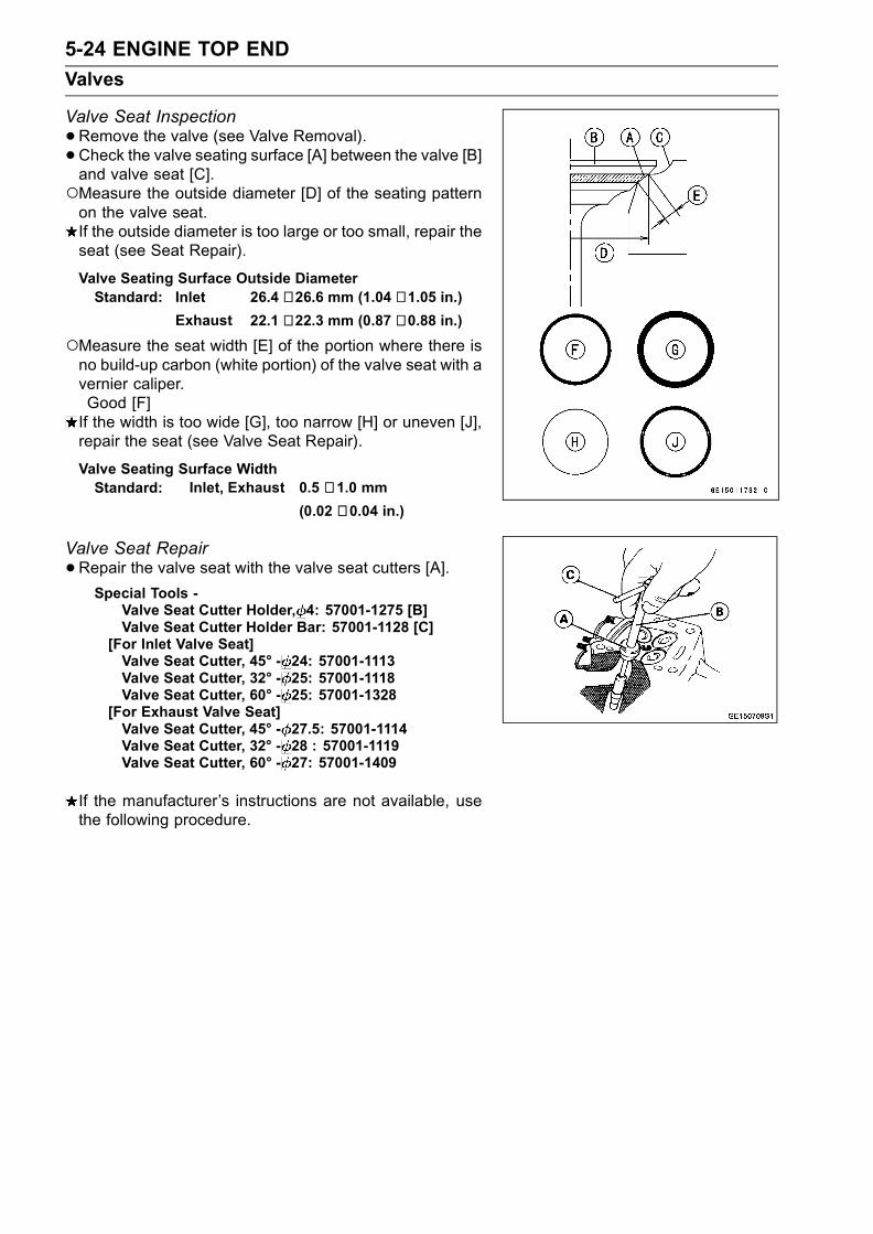
5-24 ENGINE TOP END
Valves
Valve Seat Inspection
•Remove the valve (see Valve Removal).• Check the valve seating surface [A] between the valve [B]and valve seat [C].Measure the outside diameter [D] of the seating patternon the valve seat.If the outside diameter is too large or too small, repair theseat (see Seat Repair).
Valve Seating Surface Outside DiameterStandard: Inlet 26.4 ∼ 26.6 mm (1.04 ∼ 1.05 in.)
Exhaust 22.1 ∼ 22.3 mm (0.87 ∼ 0.88 in.)
Measure the seat width [E] of the portion where there isno build-up carbon (white portion) of the valve seat with avernier caliper.Good [F]If the width is too wide [G], too narrow [H] or uneven [J],repair the seat (see Valve Seat Repair).
Valve Seating Surface WidthStandard: Inlet, Exhaust 0.5 ∼ 1.0 mm
(0.02 ∼ 0.04 in.)
Valve Seat Repair
•Repair the valve seat with the valve seat cutters [A].Special Tools -
Valve Seat Cutter Holder, 4: 57001-1275 [B]Valve Seat Cutter Holder Bar: 57001-1128 [C]
[For Inlet Valve Seat]Valve Seat Cutter, 45° - 24: 57001-1113Valve Seat Cutter, 32° - 25: 57001-1118Valve Seat Cutter, 60° - 25: 57001-1328
[For Exhaust Valve Seat]Valve Seat Cutter, 45° - 27.5: 57001-1114Valve Seat Cutter, 32° - 28 : 57001-1119Valve Seat Cutter, 60° - 27: 57001-1409
If the manufacturer’s instructions are not available, usethe following procedure.

ENGINE TOP END 5-25
Valves
Seat Cutter Operation Care:1. This valve seat cutter is developed to grind the valve forrepair. Therefore the cutter must not be used for otherpurposes than seat repair.
2. Do not drop or shock the valve seat cutter, or the dia-mond particles may fall off.
3. Do not fail to apply engine oil to the valve seat cutterbefore grinding the seat surface. Also wash off groundparticles sticking to the cutter with washing oil.
NOTEDo not use a wire brush to remove the metal particlesfrom the cutter. It will take off the diamond particles.
4. Setting the valve seat cutter holder in position, operatethe cutter in one hand. Do not apply too much force tothe diamond portion.
NOTEPrior to grinding, apply engine oil to the cutter and dur-ing the operation, wash off any ground particles stickingto the cutter with washing oil.
5. After use, wash it with washing oil and apply thin layerof engine oil before storing.
Marks Stamped on the Cutter:Themarks stamped on the back of the cutter [A] represent
the following.60° ........................... Cutter angle [B]37.5φ ........................ Outer diameter of cutter [C]
Operating Procedures:
•Clean the seat area carefully.• Coat the seat with machinist’s dye.• Fit a 45° cutter into the holder and slide it into the valveguide.
• Press down lightly on the handle and turn it right or left.Grind the seating surface only until it is smooth.
CAUTION
Do not grind the seat too much. Overgrinding willreduce valve clearance by sinking the valve into thehead. If the valve sinks too far into the head, it willbe impossible to adjust the clearance, and the cylin-der head must be replaced.
Widened Width [A] of engagement by machining with45° cutterGround Volume [B] by 32° cutter32° [C]Correct Width [D]Ground Volume [E] by 60° cutter60° [F]

5-26 ENGINE TOP END
Valves
•Measure the outside diameter of the seating surface witha vernier caliper.If the outside diameter of the seating surface is too small,repeat the 45° grind [A] until the diameter is within thespecified range.Original Seating Surface [B]
NOTERemove all pittings of flaws from 45° ground surface.After grinding with 45° cutter, apply thin coat of machin-ist’s dye to seating surface. This makes seating surfacedistinct and 32° and 60° grinding operation easier.When the valve guide is replaced, be sure to grind with45° cutter for centering and good contact.
If the outside diameter of the seating surface is too large,make the 32° grind described below.If the outside diameter [A] of the seating surface is withinthe specified range, measure the seat width as describedbelow.
•Grind the seat at a 32° angle [B] until the seat O.D. iswithin the specified range.To make the 32° grind, fit a 32° cutter into the holder, andslide it into the valve guide.Turn the holder one turn at a time while pressing downvery lightly. Check the seat after each turn.
CAUTION
The 32° cutter removes material very quickly.Check the seat outside diameter frequently to pre-vent overgrinding.
After making the 32° grind, return to the seat O.D. mea-surement step above.
• To measure the seat width, use a vernier caliper to mea-sure the width of the 45° angle portion of the seat at sev-eral places around the seat.If the seat width is too narrow, repeat the 45° grind untilthe seat is slightly too wide, and then return to the seatO.D. measurement step above.
If the seat width is too wide, make the 60° [A] grind de-scribed below.If the seat width is within the specified range, lap the valveto the seat as described below.
•Grind the seat at a 60° angle until the seat width is withinthe specified range.To make the 60° grind, fit 60° cutter into the holder, andslide it into the valve guide.Turn the holder, while pressing down lightly.After making the 60° grind, return to the seat width mea-surement step above.Correct Width [B]

ENGINE TOP END 5-27
Valves
•Lap the valve to the seat, once the seat width and O.D.are within the ranges specified above.Put a little coarse grinding compound on the face of thevalve in a number of places around the valve head.Spin the valve against the seat until the grinding com-pound produces a smooth, matched surface on both theseat and the valve.Repeat the process with a fine grinding compound.[A] Lapper[B] Valve Seat[C] Valve
• The seating area should be marked about in the middleof the valve face.If the seat area is not in the right place on the valve, checkto be sure the valve is the correct part. If it is, it may havebeen refaced too much; replace it.
• Be sure to remove all grinding compound before assem-bly.
•When the engine is assembled, be sure to adjust the valveclearance (see Engine Top End in the Periodic Mainte-nance chapter).

5-28 ENGINE TOP END
Valves

ENGINE TOP END 5-29
Cylinder, Pistons
Cylinder Removal
•Remove:Engine (see Engine Removal/Installation chapter)Cylinder Head (see Cylinder Head Removal)
•Remove the cylinder.Cylinder Installation
NOTEIf a new cylinder is used, use new piston ring.• Install the pins [A] and new cylinder gasket [B].• Apply engine oil to the cylinder bore.• Prepare two auxiliary head bolts with their head cut.• Install the two bolts [C] diagonally in the crankcase.
• The piston ring openings must be positioned as shown inthe figure. The openings of the oil ring steel rails must beabout 30 – 40° of angle from the opening of the top ring.
[A] Top Ring [D] Oil Ring Expander
[B] Second Ring [E] Lower Oil Ring Steel Rail
[C] Upper Oil Ring Steel Rail [F] Hollow
•Position the crankshaft so that all the piston heads arealmost level.
• Install the cylinder block [A].Auxiliary Head Bolts [B]Pistons [C]
• Insert the piston rings with your thumbs.
Piston Removal
•Remove the cylinder (see Cylinder Removal).• Place a clean cloth under the pistons and remove the pis-ton pin snap ring [A] from the outside of each piston.

5-30 ENGINE TOP END
Cylinder, Pistons
•Remove the piston pins.Special Tool - Piston Pin Puller Assembly: 57001-910 [A]
•Carefully spread the ring opening with your thumbs andthen push up on the opposite side of the ring [A] to removeit.
• Remove the 3-piece oil ring with your thumbs in the samemanner.
Piston Installation
NOTEIf a new piston is used, use new piston ring.• Install the piston with its marking hollow facing forward.• Fit a new piston pin snap ring into the side of the pistonso that the ring opening [A] does not coincide with the slit[B] of the piston pin hole.When installing the piston pin snap ring, compress it onlyenough to install it and no more.
CAUTION
Do not reuse snap rings, as removal weakens anddeforms them.They could fall out and score the cylinder wall.
• Install the oil ring expander [A] in the bottom piston ringgroove so the ends [B] butt together.
• Install the oil ring steel rails, one above the expander andone below it.Spread the rail with your thumbs, but only enough to fitthe rail over the piston.Release the rail into the bottom piston ring groove.
NOTEThe oil ring rails have no “top” or “bottom”.

ENGINE TOP END 5-31
Cylinder, Pistons
•Do not mix up the top and second ring.• Install the top ring [A] so that the "R" mark [B] faces up.• Install the second ring [C] so that the "RN" mark [D] facesup.
Cylinder Wear
•Since there is a difference in cylinder wear in different di-rections, take a side-to-side and a front-to-back measure-ment at each of the two locations (total of four measure-ments) shown in the figure.If any of the cylinder inside diameter measurements ex-ceeds the service limit, replace the cylinder.[A] 10 mm (0.39 in.)[B] 60 mm (2.36 in.)
Cylinder Inside DiameterStandard:
ZX636 68.000 ∼ 68.012 mm (2.677 ∼ 2.678 in.)ZX600 67.000 ∼ 67.012 mm (2.637 ∼ 2.638 in.)
Service Limit:
ZX636 68.10 mm (2.68 in.)
ZX600 67.10 mm (2.64 in.)
Piston Wear
•Measure the outside diameter [A] of each piston 5 mm(0.20 in.) [B] up from the bottom of the piston at a rightangle to the direction of the piston pin.If the measurement is under service limit, replace the pis-ton.
Piston DiameterStandard:
ZX636 67.975 ∼ 67.990 mm (2.676 ∼ 2.677 in.)ZX600 66.975 ∼ 66.990 mm (2.636 ∼ 2.637 in.)
Service Limit:
ZX636 67.83 mm (2.67 in.)
ZX600 66.83 mm (2.63 in.)

5-32 ENGINE TOP END
Cylinder, Pistons
Piston Ring, Piston Ring Groove Wear
•Check for uneven groove wear by inspecting the ring seat-ing.The rings should fit perfectly parallel to groove surfaces.If not, replace the piston and all the piston rings.
•With the piston rings in their grooves, make several mea-surements with a thickness gauge [A] to determine pistonring/groove clearance.
Piston Ring/Groove ClearanceStandard
Top ZX636 0.03 ∼ 0.05 mm(0.0012 ∼ 0.0020 in.)
ZX600 0.05 ∼ 0.09 mm(0.0020 ∼ 0.0035 in.)
Second 0.03 ∼ 0.07 mm(0.0012 ∼ 0.0028 in.)
Service Limit
Top ZX636 0.15 mm (0.0059 in.)
ZX600 0.19 mm (0.0075 in.)
Second 0.17 mm (0.0067 in.)
Piston Ring Groove Width
•Measure the piston ring groove width.Use a vernier caliper at several points around the piston.Piston Ring/Groove WidthStandard
Top ZX636 0.82 ∼ 0.84 mm(0.0322 ∼ 0.0331 in.)
ZX600 0.84 ∼ 0.86 mm(0.0331 ∼ 0.0339 in.)
Second 0.82 ∼ 0.84 mm(0.323 ∼ 0.0331 in.)
Service Limit
Top ZX636 0.92 mm (0.036 in.)
ZX600 0.94 mm (0.037 in.)
Second 0.92 mm (0.036 in.)
If the width of any of the two grooves is wider than theservice limit at any point, replace the piston.

ENGINE TOP END 5-33
Cylinder, Pistons
Piston Ring Thickness
•Measure the piston ring thickness.Use the micrometer to measure at several points aroundthe ring.
Piston Ring ThicknessStandard Service Limit
Top 0.77 ∼ 0.79 mm 0.70 mm (0.028 in.)
(0.0303 ∼ 0.0311 in.)Second 0.77 ∼ 0.79 mm 0.70 mm (0.028 in.)
(0.0303 ∼ 0.0311 in.)
If any of the measurements is less than the service limiton either of the rings, replace all the rings.
NOTEWhen using new rings in a used piston, check for un-even groove wear. The rings should fit perfectly parallelto the groove sides. If not, replace the piston.
Piston Ring End Gap
•Place the piston ring [A] inside the cylinder, using the pis-ton to locate the ring squarely in place. Set it close to thebottom of the cylinder, where cylinder wear is low.
•Measure the gap [B] between the ends of the ring with athickness gauge.
Piston Ring End GapStandard Service Limit
Top 0.12 ∼ 0.22 mm 0.5 mm (0.020 in.)
(0.0047 ∼ 0.0087 in.)Second 0.30 ∼ 0.45 mm 0.75 mm (0.031 in.)
(0.0118 ∼ 0.0177 in.)
If the end gap of either ring is greater than the servicelimit, replace all the rings.

5-34 ENGINE TOP END
Throttle Valve Holder
Throttle Valve Holder Installation
•Be sure to install the O-rings [A].• Tighten:Torque - Throttle Body Assembly Holder Bolts [B]: 12 N·m
(1.2 kgf·m, 104 in·lb)

ENGINE TOP END 5-35
Muffler
WARNINGTo avoid a serious burn, do not remove the mufflerswhen the engine is still hot. Wait until the mufflerscool down.
Exhaust Pipe Manifold Removal
•Remove:Lower Fairings (see Frame chapter)Muffler Body (see Muffler Body Removal)Radiator [A] (see Cooling System chapter)Exhaust Pipe Manifold Holder Nuts [B]Exhaust Pipe Manifold [C]
Exhaust Pipe Manifold Installation
•Replace the exhaust pipe manifold gaskets with newones.
• Tighten:Torque - Exhaust Pipe Manifold Nut: 17 N·m (1.7 kgf·m, 12
ft·lb)Exhaust Pipe Clamp Bolt: 17 N·m (1.7 kgf·m, 12ft·lb)
Muffler Body Bolt: 30 N·m (3.0 kgf·m, 22 ft·lb)
•Thoroughly warm up the engine, wait until the enginecools down, and retighten all the bolts and nuts.
Muffler Body Removal
•Remove the exhaust pipe manifold clamp bolt [A].• Remove the muffler body mounting nut [B].• Pull the muffler body backward.
Muffler Body Installation
•Replacing the muffler pipe connection gasket with newone.
• Install the muffler body and exhaust pipe.• Tighten:Torque - Exhaust Pipe Manifold Clamp Bolt: 17 N·m (1.7
kgf·m, 12 ft·lb)Muffler Body Bolt: 30 N·m (3.0 kgf·m, 22 ft·lb)
•Thoroughly warm up the engine, wait until the enginecools down, and retighten all the bolts and nuts.


CLUTCH 6-1
6
Clutch
Table of Contents
Exploded View........................................................................................................................ 6-2Specifications ......................................................................................................................... 6-4Special Tool and Sealant ........................................................................................................ 6-5Clutch Lever and Cable .......................................................................................................... 6-6
Lever Free Play Inspection ............................................................................................... 6-6Lever Free Play Adjustment.............................................................................................. 6-6Cable Removal ................................................................................................................. 6-6Cable Installation .............................................................................................................. 6-6Cable Lubrication.............................................................................................................. 6-6Clutch Lever Installation.................................................................................................... 6-6
Clutch Cover........................................................................................................................... 6-7Clutch Cover Removal ...................................................................................................... 6-7Clutch Cover Installation ................................................................................................... 6-7Release Shaft Removal .................................................................................................... 6-7Release Shaft Installation ................................................................................................. 6-7
Clutch ..................................................................................................................................... 6-8Clutch Removal................................................................................................................. 6-8Clutch Installation.............................................................................................................. 6-9Clutch Plate Assembly Inspection (ZX636)....................................................................... 6-12Clutch Plate Assembly Adjustment (ZX636) ..................................................................... 6-12Spring Plate Free Play Measurement (ZX600) ................................................................. 6-13Spring Plate Play Adjustment (ZX600) ............................................................................. 6-14Clutch Plate, Wear, Damage Inspection ........................................................................... 6-14Clutch Plate Warp Inspection............................................................................................ 6-14Clutch Spring Free Length Measurement ......................................................................... 6-15Damper Cam Inspection (ZX600) ..................................................................................... 6-15
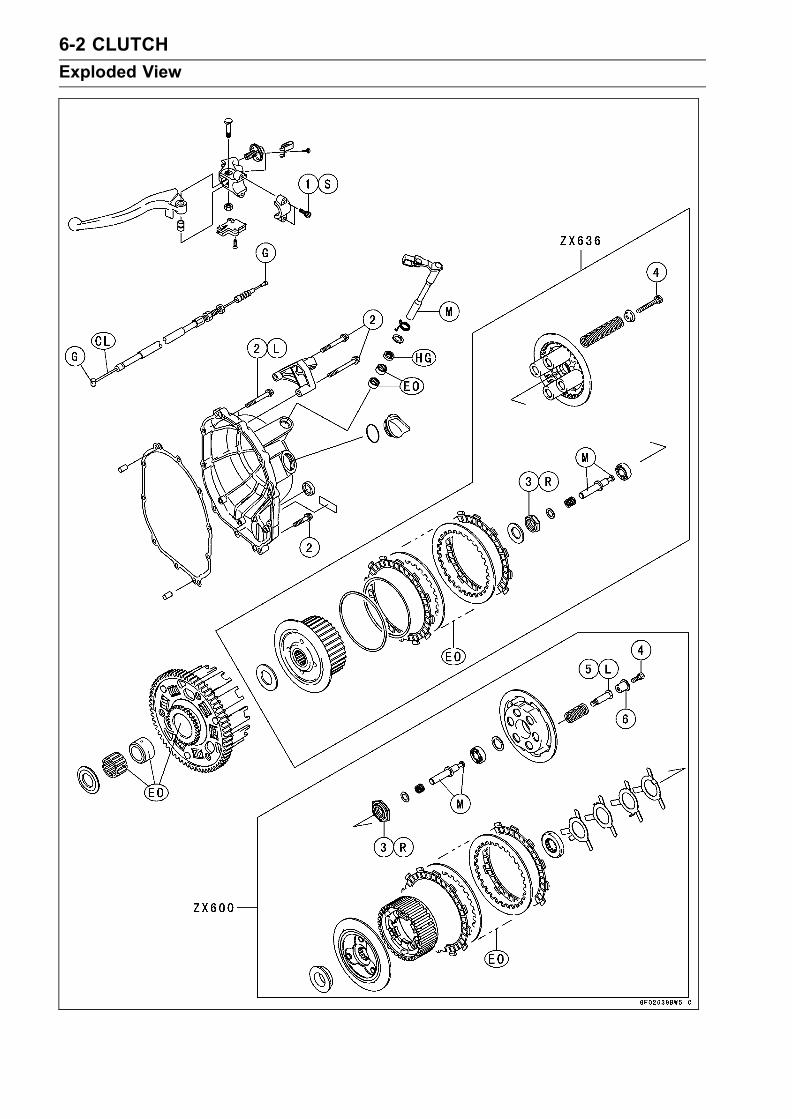
6-2 CLUTCH
Exploded View
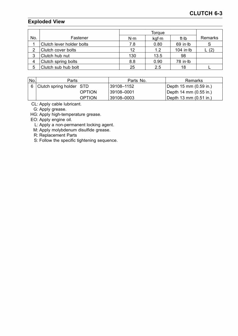
CLUTCH 6-3
Exploded View
TorqueNo. Fastener N·m kgf·m ft·lb Remarks
1 Clutch lever holder bolts 7.8 0.80 69 in·lb S2 Clutch cover bolts 12 1.2 104 in·lb L (2)3 Clutch hub nut 130 13.5 984 Clutch spring bolts 8.8 0.90 78 in·lb5 Clutch sub hub bolt 25 2.5 18 L
No. Parts Parts No. Remarks6 Clutch spring holder STD 39108–1152 Depth 15 mm (0.59 in.)
OPTION 39108–0001 Depth 14 mm (0.55 in.)OPTION 39108–0003 Depth 13 mm (0.51 in.)
CL: Apply cable lubricant.G: Apply grease.HG: Apply high-temperature grease.EO: Apply engine oil.L: Apply a non-permanent locking agent.M: Apply molybdenum disulfide grease.R: Replacement PartsS: Follow the specific tightening sequence.

6-4 CLUTCH
Specifications
Item Standard Service Limit
Clutch:
Friction plate thickness2.72 ∼ 2.88 mm (0.107 ∼ 0.113in.)
2.2 mm (0.087 in.)
Friction and steel plate warp 0.2 mm (0.008 in.) or less 0.3 mm (0.012 in.)
Clutch spring free length ZX636 80.6 mm (3.17 in.) 76.7 mm (3.02 in.)
ZX600 39.85 mm (1.57 in.) 38.5 mm (1.52 in.)
Clutch plate assembly length ZX636 37.7 ∼ 38.3 mm (1.48 ∼ 1.51 in.) – – –
ZX600 39.2 mm (1.54 in.) – – –

CLUTCH 6-5
Special Tool and Sealant
Clutch Holder:57001–1243
Kawasaki Bond (Silicone Sealant) :56019–120

6-6 CLUTCH
Clutch Lever and Cable
Lever Free Play InspectionRefer to the Clutch in the Periodic Maintenance chapter.Lever Free Play AdjustmentRefer to the Clutch in the Periodic Maintenance chapter.Cable Removal
•Remove the right lower fairing (see Frame chapter).• Slide the dust cover [A] at the clutch cable lower end outof place.
• Loosen the nuts [B], and slide the lower end [C] of theclutch cable to give the cable plenty of play.
• Screw in the adjuster.• Line up the slots [A] in the clutch lever [B], and adjuster[C], and then free the cable from the lever.
• Free the clutch inner cable tip from the clutch releaselever.
• Push the release lever toward the front of the motorcycleand tape the release lever to the clutch cover to preventthe release shaft from falling out.
• Pull the clutch cable out of the frame.
Cable Installation
•Run the clutch cable correctly (see Appendix chapter).• Adjust the clutch cable (see Clutch in the Periodic Main-tenance chapter).
Cable LubricationRefer to the General Lubrication in the Periodic Mainte-nance chapter.
Clutch Lever Installation
• Install the clutch lever so that the punch mark [A] on thehandlebar is aligned with the mating surface [B] of theclutch lever clamp.
• Tighten the upper clamp bolt first, and then the lowerclamp bolt. There will be a gap at the lower part of theclamp after tightening.
Torque - Clutch Lever Holder Bolts: 7.8 N·m (0.80 kgf·m, 69in·lb)
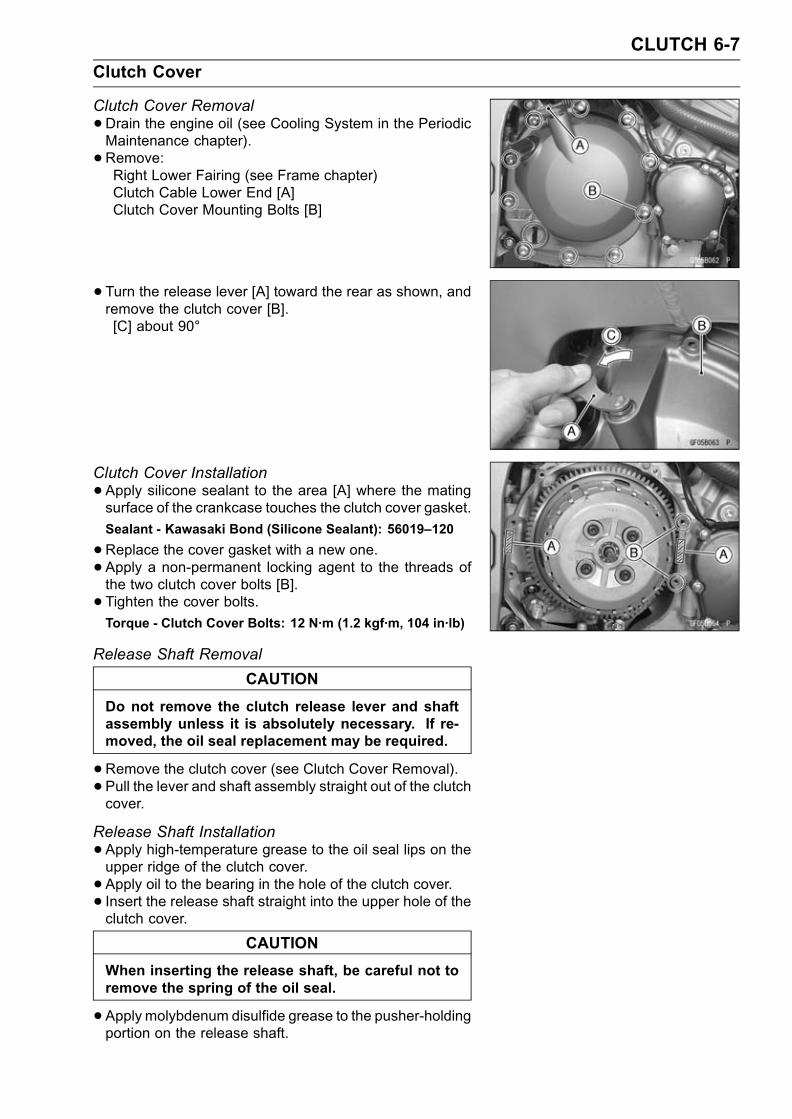
CLUTCH 6-7
Clutch Cover
Clutch Cover Removal
•Drain the engine oil (see Cooling System in the PeriodicMaintenance chapter).
• Remove:Right Lower Fairing (see Frame chapter)Clutch Cable Lower End [A]Clutch Cover Mounting Bolts [B]
• Turn the release lever [A] toward the rear as shown, andremove the clutch cover [B].[C] about 90°
Clutch Cover Installation
•Apply silicone sealant to the area [A] where the matingsurface of the crankcase touches the clutch cover gasket.
Sealant - Kawasaki Bond (Silicone Sealant): 56019–120
•Replace the cover gasket with a new one.• Apply a non-permanent locking agent to the threads ofthe two clutch cover bolts [B].
• Tighten the cover bolts.Torque - Clutch Cover Bolts: 12 N·m (1.2 kgf·m, 104 in·lb)
Release Shaft Removal
CAUTION
Do not remove the clutch release lever and shaftassembly unless it is absolutely necessary. If re-moved, the oil seal replacement may be required.
•Remove the clutch cover (see Clutch Cover Removal).• Pull the lever and shaft assembly straight out of the clutchcover.
Release Shaft Installation
•Apply high-temperature grease to the oil seal lips on theupper ridge of the clutch cover.
• Apply oil to the bearing in the hole of the clutch cover.• Insert the release shaft straight into the upper hole of theclutch cover.
CAUTION
When inserting the release shaft, be careful not toremove the spring of the oil seal.
•Apply molybdenum disulfide grease to the pusher-holdingportion on the release shaft.

6-8 CLUTCH
Clutch
Clutch Removal
•Drain the engine oil (see Engine Lubrication System inthe Periodic Maintenance chapter).
• Remove:Right Lower Fairing (see Frame chapter)Clutch Cover (see Clutch Cover Removal)Clutch Spring Bolts [A]Clutch Spring HoldersClutch SpringsClutch Spring Plate [B] (with thrust bearing and pusher[C], spring and washer)
Friction Plates, Steel PlatesSpring, Spring Seat (ZX636 only)Sub Clutch Hub Bolts [A] (ZX600 only)Clutch Hub Nut [B]
Holding the (sub) clutch hub [C], remove the nut.Special Tool - Clutch Holder: 57001-1243 [D]
ZX636:
•Remove:WasherClutch Hub
ZX600:
•Remove:Torque Limiter Springs [E]CollarSub Clutch HubClutch HubSpacer
•Using the two 4 mm screws [A], pull out the sleeve [B],needle bearing [C] and clutch housing [D].
•Remove the spacer.

CLUTCH 6-9
Clutch
Clutch Installation
• Inspect the clutch plate assembly length (see Clutch PlateAssembly Inspection).
• Install the following parts on the drive shaft.[A] Spacer[B] Sleeve[C] Needle Bearing[D] Clutch Housing[E] Spacer[F] Clutch Hub[G] Washer[H] Nut[I] Sub Clutch Hub[J] Collar[K] Torque Limiter Springs
Install the spacer [A] so that the stepped side [B] facesinward.
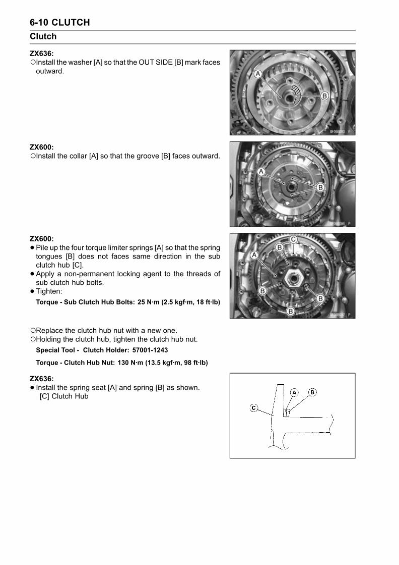
6-10 CLUTCH
Clutch
ZX636:Install the washer [A] so that the OUT SIDE [B] mark facesoutward.
ZX600:Install the collar [A] so that the groove [B] faces outward.
ZX600:
•Pile up the four torque limiter springs [A] so that the springtongues [B] does not faces same direction in the subclutch hub [C].
• Apply a non-permanent locking agent to the threads ofsub clutch hub bolts.
• Tighten:Torque - Sub Clutch Hub Bolts: 25 N·m (2.5 kgf·m, 18 ft·lb)
Replace the clutch hub nut with a new one.Holding the clutch hub, tighten the clutch hub nut.Special Tool - Clutch Holder: 57001-1243
Torque - Clutch Hub Nut: 130 N·m (13.5 kgf·m, 98 ft·lb)
ZX636:
• Install the spring seat [A] and spring [B] as shown.[C] Clutch Hub

CLUTCH 6-11
Clutch
• Install the friction plates and steel plates, starting with afriction plate and alternating them.
CAUTION
If new dry friction plates and steel plates are in-stalled, apply engine oil to the surfaces of eachplate to avoid clutch plate seizure.
Install the last friction plate [A] fitting the tangs in thegrooves in the housing as shown.
ZX636:
•Apply molybdenum disulfide grease to the pusher end[A] and install the bearing [B], pusher [C] spring [D] andwasher [E] in the clutch spring plate [F].
ZX600:
•Apply molybdenum disulfide grease to the pusher end [A]and install the shim [B], bearing [C], pusher [D] and spring[E] in the clutch spring plate [F].
• Install the clutch spring plate, spring and spring holders,and tighten the clutch spring bolts.
Torque - Clutch Spring Bolts: 8.8 N·m (0.90 kgf·m, 78 in·lb)
• Install the clutch cover (see Clutch Cover Installation).

6-12 CLUTCH
Clutch
Clutch Plate Assembly Inspection (ZX636)
• Inspect the friction plate thickness (see Clutch Plate,Wear, Damage Inspection).
•Measure the length [A] of the clutch plate assembly asshown.
ZX636:Assemble:
Clutch Hub [B] Spring Plate [G]Spring Seat [C] Springs [H]Spring [D] Spring Holders [I]Friction Plate [E] Spring Bolts [J]Steel Plate [F]
Torque - Clutch Spring Bolts: 8.8 N·m (0.90 kgf·m, 78 in·lb)
Clutch Plate AssemblyStandard: 37.7 ∼ 38.3 mm (1.48 ∼ 1.51 in.)
If the length is not within the specified range, adjust thelength (see Clutch Plate Assembly Adjustment).
Clutch Plate Assembly Adjustment (ZX636)
• Inspect the clutch plate assembly length, and then re-place the steel plate(s) which brings the length within thespecified range.Remove:Spring BoltsSpring HoldersSpringsSpring Plate
Replace the following steel plate(s).Part No. Thickness
13089–1126 1.4 mm (0.055 in.)
13089–013 1.6 mm (0.063 in.) (STD)
13089–1073 2.0 mm (0.079 in.)
NOTEDo not use the steel plate of 1.4 mm (0.055 in.) and 2.0mm (0.0079 in.) thickness at the same time.
• Install the removed parts, and inspect the clutch plate as-sembly length.
Torque - Clutch Spring Bolts: 8.8 N·m (0.90 kgf·m, 78 in·lb)

CLUTCH 6-13
Clutch
Spring Plate Free Play Measurement (ZX600)Insufficient clutch free play will cause the engine braking
effect to be more sudden, resulting in rear wheel hop. Onthe other hand, if the free play is excessive, the clutch levermay feel “spongy” or pulsate when pulled.
•Hold an extra drive shaft in a vise and install the followingclutch parts on the shaft.[A] Spacer[B] Needle Bearing[C] Bushing[D] Clutch Housing[E] Spacer[F] Clutch Hub[G] Sub Clutch Hub[H] Friction Plates[I] Steel Plates[J] Spring Plate
•Engage the cam followers (Clutch Hub) with the cams(Sub Clutch Hub).
• To measure the free play, set a dial gauge [A] against theraised center [B] of the clutch spring plate.
•Move the clutch housing gear back and forth [C]. The dif-ference between the highest and lowest gauge readingsis the amount of free play.[D] Drive Shaft
•Measure the spring plate free play (see Spring Plate FreePlay Measurement).
Spring Plate Free PlayUsable range: 0.05 ∼ 0.35 mm (0.002 ∼ 0.014 in.)
If the free play is not within the usable range, change allof the friction plate.

6-14 CLUTCH
Clutch
Spring Plate Play Adjustment (ZX600)Apply a non permanent locking agent to the thread of subclutch hub bolts.
• Assemble the following parts so that the clutch plate as-sembly length [A] is specified length.
Clutch Hub [B] Spring Plate [G]Sub Clutch Hub [C] Springs [H]Sub Clutch Hub Bolts[D] Spring Holders [I]Friction Plate [E] Spring Bolts [J]Steel Plate [F]
Replace the following steel plate(s).Part No. Thickness
13089–1126 1.4 mm (0.055 in.)
13089–013 1.6 mm (0.063 in.) (STD)
13089–1073 2.0 mm (0.079 in.)
NOTEDo not use the steel plate of 1.4 mm (0.055 in.) and 2.0mm (0.079 in.) thickness at the same time.
Torque - Sub Clutch Hub Bolts: 25 N·m (2.5 kgf·m, 18 ft·lb)Clutch Spring Bolts: 8.8 N·m (0.90 kgf·m, 78 in·lb)
Clutch Plate AssemblyStandard: 39.2 mm (1.54 in.)
Clutch Plate, Wear, Damage Inspection
•Visually inspect the friction and steel plates for signs ofseizure, overheating (discoloration), or uneven wear.
•Measure the thickness of each friction plate [A] at severalpoints.If any plates show signs of damage, or if they have wornpast the service limit, replace them with new ones.
Friction Plate ThicknessStandard: 2.72 ∼ 2.88 mm (0.107 ∼ 0.113 in.)Service Limit: 2.2 mm (0.087 in.)
Clutch Plate Warp Inspection
•Place each friction plate or steel plate on a surface plateand measure the gap between the surface plate [A] andeach friction plate or steel plate [B] with a thickness gauge[C]. The gap is the amount of friction or steel plate warp.If any plate is warped over the service limit, replace it witha new one.
Friction and Steel Plate WarpStandard: 0.2 mm (0.008 in.) or less
Service Limit: 0.3 mm (0.012 in.)
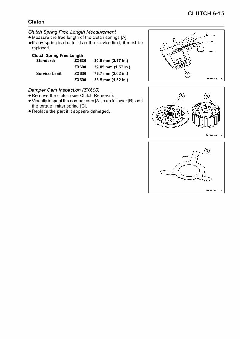
CLUTCH 6-15
Clutch
Clutch Spring Free Length Measurement
•Measure the free length of the clutch springs [A].If any spring is shorter than the service limit, it must bereplaced.
Clutch Spring Free LengthStandard: ZX636 80.6 mm (3.17 in.)
ZX600 39.85 mm (1.57 in.)
Service Limit: ZX636 76.7 mm (3.02 in.)
ZX600 38.5 mm (1.52 in.)
Damper Cam Inspection (ZX600)
•Remove the clutch (see Clutch Removal).• Visually inspect the damper cam [A], cam follower [B], andthe torque limiter spring [C].
•Replace the part if it appears damaged.


ENGINE LUBRICATION SYSTEM 7-1
7
Engine Lubrication System
Table of Contents
Exploded View........................................................................................................................ 7-2Engine Oil Flow Chart............................................................................................................. 7-4Specifications ......................................................................................................................... 7-5Special Tools and Sealant ...................................................................................................... 7-6Engine Oil and Oil Filter.......................................................................................................... 7-7
Oil Level Inspection........................................................................................................... 7-7Engine Oil Change............................................................................................................ 7-7Oil Filter Replacement ...................................................................................................... 7-7
Oil Pan.................................................................................................................................... 7-8Oil Pan Removal ............................................................................................................... 7-8Oil Pan Installation............................................................................................................ 7-8
Oil Pressure Relief Valve........................................................................................................ 7-9Oil Pressure Relief Valve Removal ................................................................................... 7-9Oil Pressure Relief Valve Installation ................................................................................ 7-9Oil Pressure Relief Valve Inspection................................................................................. 7-9
Oil Pump................................................................................................................................. 7-10Oil Pump Removal ............................................................................................................ 7-10Oil Pump Installation ......................................................................................................... 7-10Oil Pump Drive Gear Removal.......................................................................................... 7-11Oil Pump Drive Gear Installation....................................................................................... 7-11
Oil Cooler................................................................................................................................ 7-12Oil Cooler Removal........................................................................................................... 7-12Oil Cooler Installation........................................................................................................ 7-12
Oil Pressure Measurement..................................................................................................... 7-13Oil Pressure Measurement ............................................................................................... 7-13
Oil Pressure Switch ................................................................................................................ 7-14Oil Pressure Switch Removal ........................................................................................... 7-14Oil Pressure Switch Installation ........................................................................................ 7-14

7-2 ENGINE LUBRICATION SYSTEM
Exploded View

ENGINE LUBRICATION SYSTEM 7-3
Exploded View
TorqueNo. Fastener N·m kgf·m ft·lb Remarks
1 Oil jet nozzle bolts 6.9 0.70 61 in·lb L2 Oil pressure switch 15 1.5 11 SS3 Oil pressure switch terminal bolt 1.5 0.15 13 in·lb G4 Oil pipe holder bolts 12 1.2 104 in·lb5 Oil passage plug 15 1.5 116 Oil filler plug 1.5 0.15 13 in·lb7 Cooling hose clamp 2 0.20 17 in·lb8 Oil cooler bolt 78 8.0 58 R9 Impeller bolt 9.8 1.0 87 in·lb10 Water pump cover bolts 12 1.2 104 in·lb L11 Coolant drain plug 9.8 1.0 87 in·lb12 Oil pressure relief valve 15 1.5 11 L13 Oil filter 31 3.2 23 R,EO14 Oil filter clamp bolt 5.9 0.60 52 in·lb15 Engine drain plug 29 3.0 2216 Oil pan bolts 9.8 1.0 87 in·lb
SS: Apply silicone sealant.L: Apply a non-permanent locking agent.R: Replacement PartsG: Apply grease.EO: Apply engine oil.W: Apply water.MO: Apply molybdenum disulfide oil solution.

7-4 ENGINE LUBRICATION SYSTEM
Engine Oil Flow Chart
1. Oil Pan2. Oil Screen3. Oil Pump4. Relief Valve5. Oil Filter6. Oil Cooler7. Crankshaft8. To Connecting Rod Journals9. Starter Clutch Gear10. Alternator Rotor11. Starter Clutch Oil Passage Hole
12. Drive Shaft13. Output Shaft14. Oil Pressure Switch15. Cylinder Head16. Camshaft Cap17. Camshaft18. Oil Passage19. Oil Pipe20. Oil Drain Plug21. Oil Jet Nozzles

ENGINE LUBRICATION SYSTEM 7-5
Specifications
Item Standard
Engine Oil:
Type API SE, SF or SG
API SH or SJ with JASO MA
Viscosity SAE 10W-40
Capacity 3.4 L (3.6 US qt, when filter is not removed)
3.6 L (3.8 US qt, when filter is removed)
4.0 L (4.2 US qt, when engine is completely dry)
Level Between upper and lower level lines
Oil Pressure Measurement:
Oil pressure @4 000 r/min (rpm),
oil temp. 90°C (194°F) 140 ∼ 200 kPa (1.4 ∼ 2.0 kgf/cm², 207 ∼ 29 psi)

7-6 ENGINE LUBRICATION SYSTEM
Special Tools and Sealant
Outside Circlip Pliers:57001–144
Oil Pressure Gauge, 10 kgf/cm²:57001–164
Oil Filter Wrench:57001–1249
Oil Pressure Gauge Adapter, M18 × 1.5:57001–1278
Kawasaki Bond (Silicone Sealant):56019–120

ENGINE LUBRICATION SYSTEM 7-7
Engine Oil and Oil Filter
WARNINGMotorcycle operation with insufficient, deteri-orated, or contaminated engine oil will causeaccelerated wear and may result in engine or trans-mission seizure, accident, and injury.
Oil Level Inspection
•Check that the engine oil level is between the upper [A]and lower [B] levels in the gauge.
NOTESituate the motorcycle so that it is perpendicular to theground.If the motorcycle has just been used, wait several min-utes for all the oil to drain down.If the oil has just been changed, start the engine andrun it for several minutes at idle speed. This fills the oilfilter with oil. Stop the engine, then wait several minutesuntil the oil settles.
CAUTION
Racing the engine before the oil reaches every partcan cause engine seizure.If the engine oil gets extremely low or if the oil pumpor oil passages clog up or otherwise do not functionproperly, the oil pressure warning light will light. Ifthis light stays onwhen the engine is running aboveidle speed, stop the engine immediately and find thecause.
Engine Oil ChangeRefer to the Engine Lubrication System in the PeriodicMaintenance chapter.
Oil Filter ReplacementRefer to the Engine Lubrication System in the PeriodicMaintenance chapter.

7-8 ENGINE LUBRICATION SYSTEM
Oil Pan
Oil Pan Removal
•Drain the Engine Oil (see Engine Lubrication System inthe Periodic Maintenance chapter).
• Remove:Muffler (see Engine Top End chapter)Oil Pan Bolts [A]Oil Pan [B]
Oil Pan Installation
•Clean the oil screen [A].• Install the oil screen so that the crankcase rib [B] fits theslot [C] of the oil screen.
• Apply grease to the O-rings on the oil pipes [A].If the relief valve was removed, install it.Apply a non-permanent locking agent to the threads ofthe relief valve [B], and tighten it.
Torque - Oil Pressure Relief Valve: 15 N·m (1.5 kgf·m, 11ft·lb)
CAUTION
Do not apply too much non-permanent lockingagent to the threads. This may block the oil pas-sage.
•Replace the oil pan gasket with a new one.• Tighten:Torque - Oil Pan Bolts: 9.8 N·m (1.0 kgf·m, 87 in·lb)
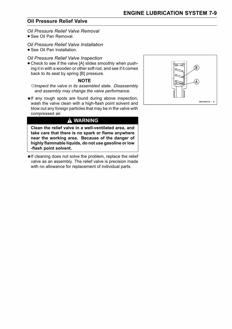
ENGINE LUBRICATION SYSTEM 7-9
Oil Pressure Relief Valve
Oil Pressure Relief Valve Removal
•See Oil Pan Removal.Oil Pressure Relief Valve Installation
•See Oil Pan Installation.Oil Pressure Relief Valve Inspection
•Check to see if the valve [A] slides smoothly when push-ing it in with a wooden or other soft rod, and see if it comesback to its seat by spring [B] pressure.
NOTEInspect the valve in its assembled state. Disassemblyand assembly may change the valve performance.
If any rough spots are found during above inspection,wash the valve clean with a high-flash point solvent andblow out any foreign particles that may be in the valve withcompressed air.
WARNINGClean the relief valve in a well-ventilated area, andtake care that there is no spark or flame anywherenear the working area. Because of the danger ofhighly flammable liquids, do not use gasoline or low-flash point solvent.
If cleaning does not solve the problem, replace the reliefvalve as an assembly. The relief valve is precision madewith no allowance for replacement of individual parts.

7-10 ENGINE LUBRICATION SYSTEM
Oil Pump
Oil Pump Removal
•Drain:Coolant (see Cooling System in the Periodic Mainte-nance chapter)Engine Oil (see Engine Lubrication System in the Peri-odic Maintenance chapter)
•Remove:Water Hoses [A]Bolts [B] and Water Pump Cover [C]
Impeller Bolt [A]Impeller [B]
Water Pump Body [A]Oil Pump Cover [B]Oil (Water) Pump Shaft [C]Outer Rotor [D] and Inner Rotor [E]
NOTEThe oil (water) pump assembly can easily be removedby installing water pump cover bolt [F] into the oil (water)pump shaft and pulling them.
Oil Pump Installation
• Install the outer rotor [A] in to the crankcase.• Install the pin [B], inner rotor [C] and oil (water) pump shaft[D].Turn the pump shaft so that the slot [E] in its shaft fits ontothe projection [F] of the pump drive gear shaft.
• Fit the pin [A] of the oil pump cover [B] into the hole [C] inthe crankcase.

ENGINE LUBRICATION SYSTEM 7-11
Oil Pump
• Install:Pins [A]Water Pump Body [B]
• Apply coolant to the surface of the rubber seal on theimpeller.
• Install the impeller [A] and bolt [B].Torque - Impeller Bolt: 9.8 N·m (1.0 kgf·m, 87 in·lb)
Pins [C]Water Pump Cover [D]
• Apply a non-permanent locking agent to the threads ofthe water pump cover bolts, and tighten them.
Torque - Water Pump Cover Bolts: 12 N·m (1.2 kgf·m, 104in·lb)
Oil Pump Drive Gear Removal
•Remove:Clutch (see Clutch chapter)Oil Pan (see Oil Pan Removal)Circlip [A] and Washer [B]
Special Tool - Circlip Pliers: 57001–144
•Pull the oil pump drive gear [A].
Oil Pump Drive Gear Installation
• Install the circlip [A] into the groove [B] of the oil pumpdrive gear shaft.
Special Tool - Circlip Pliers: 57001–144

7-12 ENGINE LUBRICATION SYSTEM
Oil Cooler
Oil Cooler Removal
•Remove:Lower Fairing (see Frame chapter)
•Drain:Engine Oil (see Engine Lubrication System in the Peri-odic Maintenance chapter)Coolant (see Cooling System in the Periodic Mainte-nance chapter)
•Remove the oil filter (see Engine Lubrication System inthe Periodic Maintenance chapter).
• Remove the oil cooler hoses [A] from the oil cooler.•Unscrew the oil cooler bolt [B] from the crankcase, andremove the oil cooler [C].
Oil Cooler Installation
•Replace the oil cooler bolt with a new one.•Clean off any oil or dirt on internal threads of oil coolerbolt in crankcase.
• Apply grease to the O-ring [A] before installation.
• Install the oil cooler so that the crankcase rib [A] fits theslot [B] of the oil cooler plate.
• Tighten:Torque - Oil Cooler Bolt: 78 N·m (8.0 kgf·m, 58 ft·lb)
•Pour:Engine Oil (see Engine Lubrication System in the Peri-odic Maintenance chapter)Coolant (see Cooling System chapter)
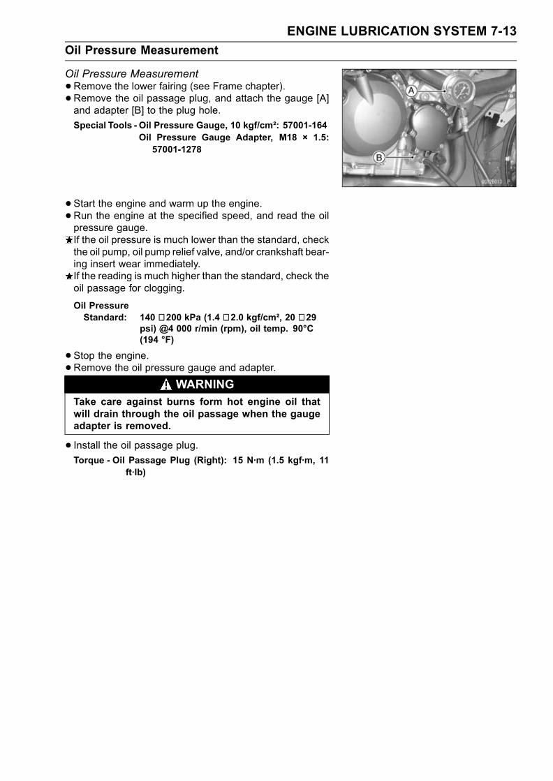
ENGINE LUBRICATION SYSTEM 7-13
Oil Pressure Measurement
Oil Pressure Measurement
•Remove the lower fairing (see Frame chapter).• Remove the oil passage plug, and attach the gauge [A]and adapter [B] to the plug hole.
Special Tools - Oil Pressure Gauge, 10 kgf/cm²: 57001-164Oil Pressure Gauge Adapter, M18 × 1.5:57001-1278
•Start the engine and warm up the engine.
•Run the engine at the specified speed, and read the oilpressure gauge.If the oil pressure is much lower than the standard, checkthe oil pump, oil pump relief valve, and/or crankshaft bear-ing insert wear immediately.If the reading is much higher than the standard, check theoil passage for clogging.
Oil PressureStandard: 140 ∼ 200 kPa (1.4 ∼ 2.0 kgf/cm², 20 ∼ 29
psi) @4 000 r/min (rpm), oil temp. 90°C(194 °F)
•Stop the engine.•Remove the oil pressure gauge and adapter.
WARNINGTake care against burns form hot engine oil thatwill drain through the oil passage when the gaugeadapter is removed.
• Install the oil passage plug.Torque - Oil Passage Plug (Right): 15 N·m (1.5 kgf·m, 11
ft·lb)
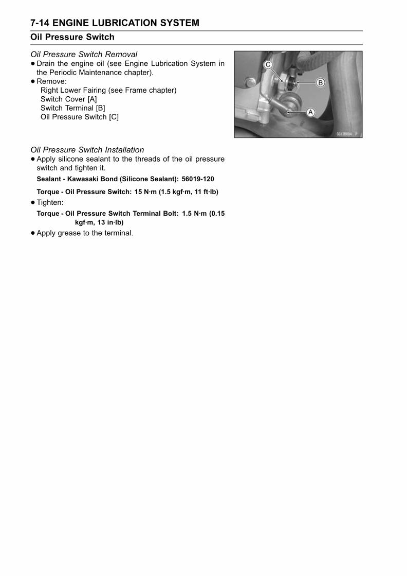
7-14 ENGINE LUBRICATION SYSTEM
Oil Pressure Switch
Oil Pressure Switch Removal
•Drain the engine oil (see Engine Lubrication System inthe Periodic Maintenance chapter).
• Remove:Right Lower Fairing (see Frame chapter)Switch Cover [A]Switch Terminal [B]Oil Pressure Switch [C]
Oil Pressure Switch Installation
•Apply silicone sealant to the threads of the oil pressureswitch and tighten it.
Sealant - Kawasaki Bond (Silicone Sealant): 56019-120
Torque - Oil Pressure Switch: 15 N·m (1.5 kgf·m, 11 ft·lb)
•Tighten:Torque - Oil Pressure Switch Terminal Bolt: 1.5 N·m (0.15
kgf·m, 13 in·lb)
•Apply grease to the terminal.
ENGINE REMOVAL/INSTALLATION 8-1
8
Engine Removal/Installation
Table of Contents
Exploded View........................................................................................................................ 8-2Special Tools .......................................................................................................................... 8-4Engine Removal/Installation ................................................................................................... 8-5
Engine Removal................................................................................................................ 8-5Engine Installation............................................................................................................. 8-7
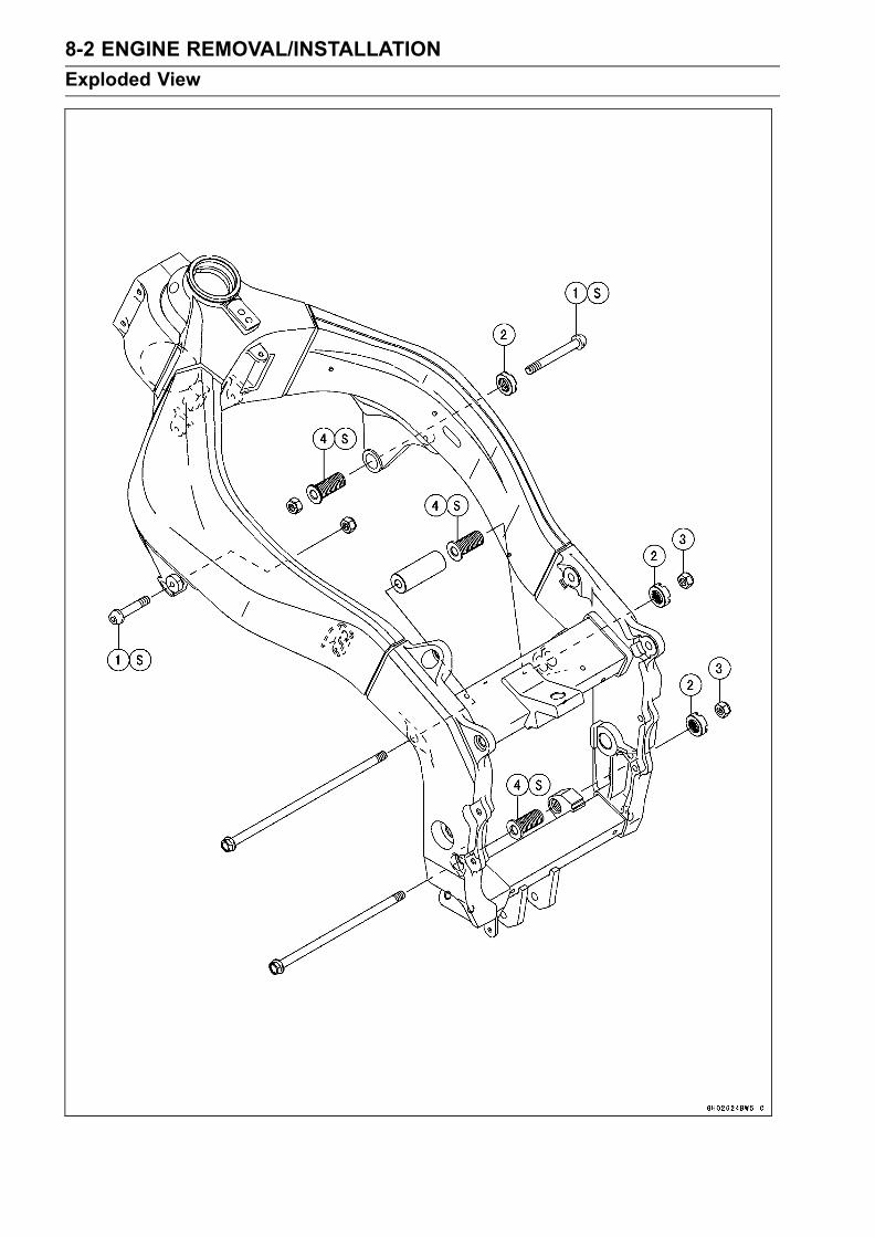
8-2 ENGINE REMOVAL/INSTALLATION
Exploded View

ENGINE REMOVAL/INSTALLATION 8-3
Exploded View
TorqueNo. Fastener N·m kgf·m ft·lb Remarks
1 Engine mounting bolts 44 4.5 33 S2 Engine mounting locknuts 49 5.0 363 Engine mounting nuts 44 4.5 334 Engine mounting adjusting bolts 20 2.0 14 S
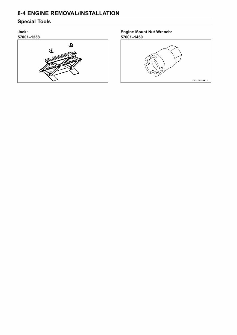
8-4 ENGINE REMOVAL/INSTALLATION
Special Tools
Jack:57001–1238
Engine Mount Nut Wrench:57001–1450
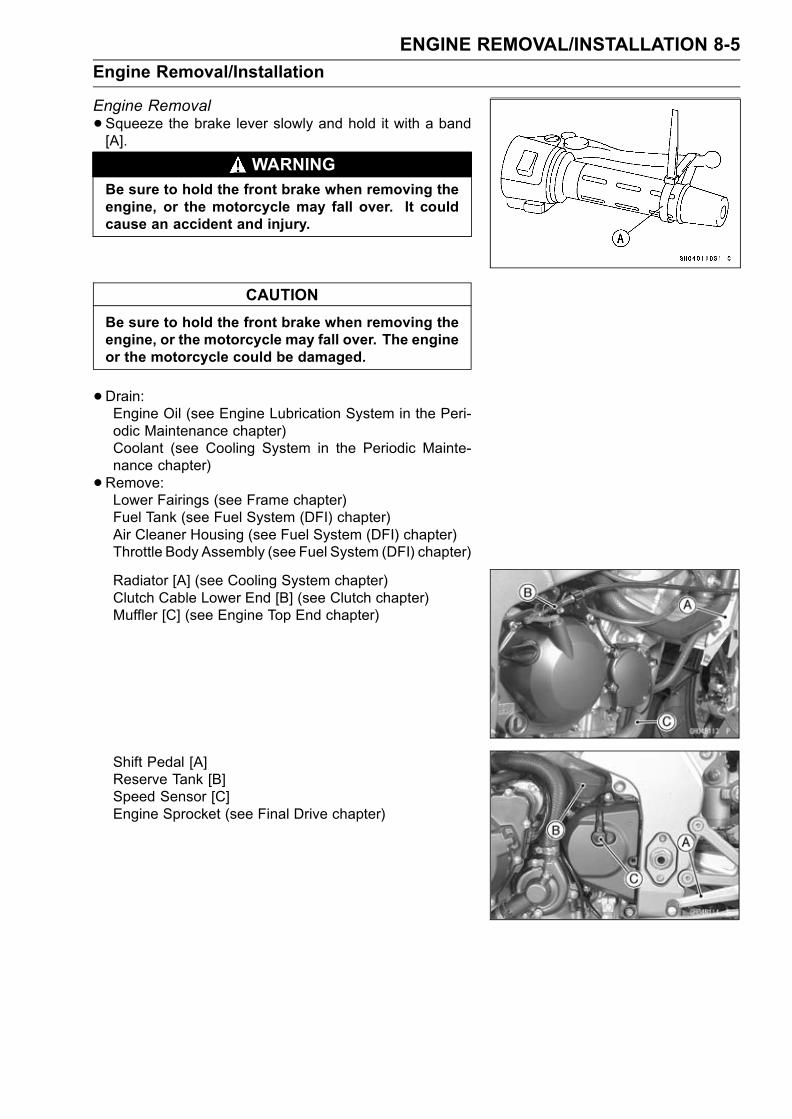
ENGINE REMOVAL/INSTALLATION 8-5
Engine Removal/Installation
Engine Removal
•Squeeze the brake lever slowly and hold it with a band[A].
WARNINGBe sure to hold the front brake when removing theengine, or the motorcycle may fall over. It couldcause an accident and injury.
CAUTION
Be sure to hold the front brake when removing theengine, or the motorcycle may fall over. The engineor the motorcycle could be damaged.
•Drain:Engine Oil (see Engine Lubrication System in the Peri-odic Maintenance chapter)Coolant (see Cooling System in the Periodic Mainte-nance chapter)
•Remove:Lower Fairings (see Frame chapter)Fuel Tank (see Fuel System (DFI) chapter)Air Cleaner Housing (see Fuel System (DFI) chapter)Throttle Body Assembly (see Fuel System (DFI) chapter)
Radiator [A] (see Cooling System chapter)Clutch Cable Lower End [B] (see Clutch chapter)Muffler [C] (see Engine Top End chapter)
Shift Pedal [A]Reserve Tank [B]Speed Sensor [C]Engine Sprocket (see Final Drive chapter)

8-6 ENGINE REMOVAL/INSTALLATION
Engine Removal/Installation
•Pull off the connectors from the engine and free the wiringfrom the clamps.Pickup Coil Lead Connector [A]Battery Ground Lead [B]Starter Motor Lead [C]Alternator Lead Connector [D]Side Stand Switch Lead Connector [E]Speed Sensor Connector [F]Regulator/Rectifier Lead Connector [G]
Stick Coil Harness Connector [A]
• Support the rear part of the frame on the jack.Special Tool - Jack: 57001-1238
•Remove:Water Hoses [A]
• Support the engine with a suitable stand [A].•Remove the engine mounting bolts and nuts [B].• Loosen the locknuts and adjusting bolts [C].Special Tool - Engine Mount Nut Wrench: 57001–1450
•Remove the drive chain from the output shaft.
• Using the stand, take out the engine.

ENGINE REMOVAL/INSTALLATION 8-7
Engine Removal/Installation
Engine Installation
•Support the engine with a suitable stand.•Hang the drive chain over the output shaft just beforemoving the engine into its final position in the frame.
• Screw the adjusting bolts [A], [B], [C] into the frame.• Insert the lower mounting bolt [D] from the left side.
• Insert the upper mounting bolts [E] and [F] from the leftand right side individually.
• Set the collar [G] and insert the middle mounting bolts [H]from the left side.

8-8 ENGINE REMOVAL/INSTALLATION
Engine Removal/Installation
•Turn the adjusting bolt [A], [B] until the clearance [X], [Y]between the crankcase and frame come to zero mm (zeroin.).
Torque - Engine Mounting Adjusting Bolt: 20 N·m (2.0kgf·m, 14 ft·lb)
•Tighten the engine mounting bolts [E], [D], [H] with spec-ified torque.Tightening order is engine mounting bolts [E], [H] to [D].Torque - EngineMounting Bolts: 44 N·m (4.5 kgf·m, 33 ft·lb)
•Pull out the engine mounting bolt [F] temporarily, and turnthe adjusting bolt [C] until the clearance [Z] between theadjusting bolt and cylinder come to zero mm (zero in.) byhand.
• Insert the bolt [F] into engine mounting hole, and tightenthe bolt and locknut [K], [J] with specified torque
Torque - EngineMounting Bolts: 44 N·m (4.5 kgf·m, 33 ft·lb)Engine Mounting Locknut: 49 N·m (5.0 kgf·m, 36ft·lb)
Special Tool - Engine Mount Nut Wrench: 57001–1450
•Run the leads, cables and hoses correctly (see Cable,Wire and Hose Routing section in Appendix chapter).
• Install the removed parts (see appropriate chapters).• Adjust:Throttle Cables (see Fuel System (DFI) in the PeriodicMaintenance chapter)Choke Cable (see Fuel System (DFI) chapter)Clutch Cable (see Clutch chapter)Drive Chain (see Final Drive in the Periodic Maintenancechapter)
• Fill the engine with engine oil (see Engine LubricationSystem in the Periodic Maintenance chapter).
• Fill the engine with coolant and bleed the air from the cool-ing system (see Cooling System in the Periodic Mainte-nance chapter).

CRANKSHAFT / TRANSMISSION 9-1
9
Crankshaft / Transmission
Table of Contents
Exploded View........................................................................................................................ 9-2Specifications ......................................................................................................................... 9-6Special Tools and Sealant ...................................................................................................... 9-8Crankcase Splitting................................................................................................................. 9-9
Crankcase Splitting ........................................................................................................... 9-9Crankcase Assembly ........................................................................................................ 9-9
Crankshaft and Connecting Rods........................................................................................... 9-12Crankshaft Removal ......................................................................................................... 9-12Crankshaft Installation ...................................................................................................... 9-12Connecting Rod Removal ................................................................................................. 9-12Connecting Rod Installation .............................................................................................. 9-12Crankshaft/Connecting Rod Cleaning............................................................................... 9-16Connecting Rod Bend....................................................................................................... 9-16Connecting Rod Twist ....................................................................................................... 9-16Connecting Rod Big End Side Clearance ......................................................................... 9-16Connecting Rod Big End Bearing Insert/Crankpin Wear .................................................. 9-17Crankshaft Side Clearance ............................................................................................... 9-18Crankshaft Runout ............................................................................................................ 9-19Crankshaft Main Bearing Insert/Journal Wear .................................................................. 9-19
Starter Motor Clutch ............................................................................................................... 9-21Starter Motor Clutch Removal/Installation ........................................................................ 9-21Starter Motor Clutch Inspection ........................................................................................ 9-21Starter Motor Clutch Disassembly .................................................................................... 9-21Starter Motor Clutch Assembly ......................................................................................... 9-21
Transmission .......................................................................................................................... 9-22Shift Pedal Removal ......................................................................................................... 9-22Shift Pedal Installation ...................................................................................................... 9-22External Shift Mechanism Removal .................................................................................. 9-22External Shift Mechanism Installation ............................................................................... 9-22External Shift Mechanism Inspection................................................................................ 9-23Transmission Shaft Removal ............................................................................................ 9-23Transmission Shaft Installation ......................................................................................... 9-23Transmission Shaft Disassembly...................................................................................... 9-24Transmission Shaft Assembly........................................................................................... 9-24Shift Drum and Fork Removal........................................................................................... 9-26Shift Drum and Fork Installation........................................................................................ 9-26Shift Drum Disassembly.................................................................................................... 9-26Shift Drum Assembly ........................................................................................................ 9-27Shift Fork Bending ............................................................................................................ 9-27Shift Fork/Gear Groove Wear ........................................................................................... 9-27Shift Fork Guide Pin/Drum Groove Wear.......................................................................... 9-28Gear Dog and Gear Dog Hole Damage............................................................................ 9-28
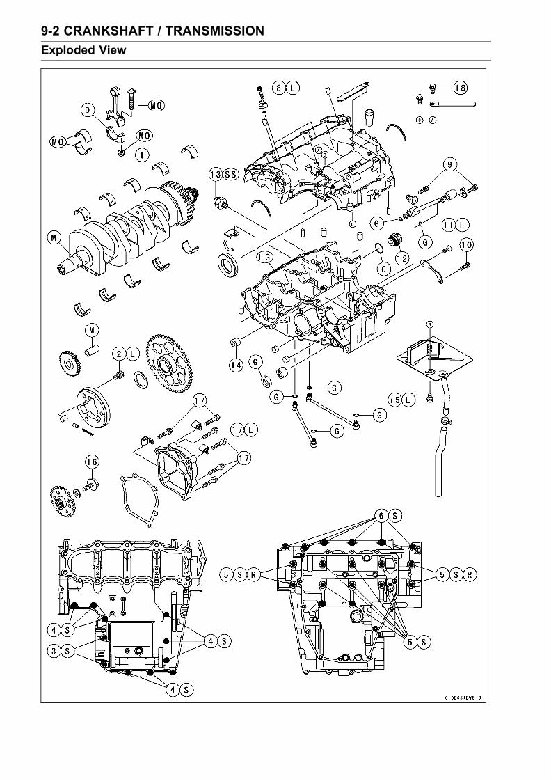
9-2 CRANKSHAFT / TRANSMISSION
Exploded View

CRANKSHAFT / TRANSMISSION 9-3
Exploded View
TorqueNo. Fastener N·m kgf·m ft·lb Remarks
1 Connecting rod big end nuts See the text
2 Starter motor clutch bolts 33 3.4 24 L
3 Upper crankcase bolts (7 mm) 20 2.0 14.5 S
4 Upper crankcase bolts (6 mm) 12 1.2 104 in·lb S
5 Lower crankcase bolts (7 mm) 24 2.4 18 S
6 Lower crankcase bolts (7 mm) 27 2.8 20 S
7 Lower crankcase bolts (6 mm) 12 1.2 104 in·lb S
8 Oil jet nozzle bolts 6.9 0.70 61 in·lb L
9 Oil pipe holder bolt 12 1.2 104 in·lb
10 Shift drum bearing holder bolt 12 1.2 104 in·lb
11 Shift drum bearing holder screw 4.9 0.50 43 in·lb L
12 Oil passage plug (Right) 15 1.5 11
13 Oil pressure switch 15 1.5 11 SS
14 Oil passage plug (Left) 20 2.0 14.5 L
15 Breather plate bolts 9.8 1.0 87 in·lb L
16 Timing rotor bolts 44 4.5 33
17 Crankshaft sensor cover bolts 9.8 1.0 87 in·lb L (1)
18 Harness clamp bolt 8.8 0.90 78 in·lb L
D: Do not apply any grease or oil.G: Apply grease.L: Apply a non-permanent locking agent.M: Apply molybdenum disulfide grease.SS: Apply silicone sealant.LG: Apply liquid gasket (Kawasaki Bond: 92104–1064).MO: Apply molybdenum disulfide oil solution.R: Replacement PartsS: Follow the specific tightening sequence.

9-4 CRANKSHAFT / TRANSMISSION
Exploded View

CRANKSHAFT / TRANSMISSION 9-5
Exploded View
TorqueNo. Fastener N·m kgf·m ft·lb Remarks
1 Shift drum cam holder bolt 12 1.2 104 in·lb L
2 Neutral switch 15 1.5 11
3 Gear positioning lever bolt 9.8 1.0 87 in·lb
4 Shift shaft return spring pin 28 2.9 21 L
G: Apply grease.L: Apply a non-permanent locking agent.
EO: Apply engine oil.R: Replacement Parts

9-6 CRANKSHAFT / TRANSMISSION
Specifications
Item Standard Service Limit
Crankshaft, Connecting Rods:
Connecting rod big end side clearance 0.13 ∼ 0.33 mm(0.0051 ∼ 0.00130 in.)
0.5 mm (0.020 in.)
Connecting rod big end bearing insert/crankpin clearance
0.035 ∼ 0.064 mm (0.0014 ∼ 0.0025in.)
0.10 mm (0.004 in.)
Crankpin diameter: 29.984 ∼ 30.000 mm (1.1805 ∼1.1811 in.)
29.97 mm (1.18 in.)
MarkingNone
29.984 ∼ 29.994 mm (1.1805 ∼1.1809 in.)
– – –
29.995 ∼ 30.000 mm (1.1809∼ 1.1811 in.)
– – –
Connecting rod big end bore diameter: 33.000 ∼ 33.016 mm (1.2992 ∼1.2998 in.)
– – –
MarkingNone
33.000 ∼ 33.008 mm (1.2992 ∼1.2995 in.)
– – –
33.009 ∼ 33.016 mm (1.2996 ∼1.2998 in.)
– – –
Connecting rod big end bearing
insert thickness:
Pink1.475 ∼ 1.480 mm (0.0581 ∼ 0.0583in.)
– – –
Brown1.480 ∼ 1.485 mm (0.0583 ∼ 0.0585in.)
– – –
Black1.485 ∼ 1.490 mm (0.0585 ∼ 0.0587in.)
– – –
Connecting rod big end bearing insert selection:
Con-rod Big EndBore DiameterMarking
CrankpinDiameterMarking
Bearing Insert
Size Color Part Number
None Pink 92028-1880
None None Brown 92028-1879
None Black 92028-1878
Crankshaft side clearance 0.05 ∼ 0.15 mm (0.002 ∼ 0.006 in.) 0.35 mm (0.014 in.)
Crankshaft runout TIR 0.02 mm (0.0008 in.) or less TIR 0.05 mm (0.002in.)
Crankshaft main bearing insert/journalclearance
0.031 ∼ 0.059 mm (0.0012 ∼ 0.0023in.)
0.10 mm (0.0039 in.)
Crankshaft main journal diameter: 29.984 ∼ 30.000 mm (1.1805 ∼1.1811 in.)
29.96 mm (1.18 in.)
MarkingNone
29.984 ∼ 29.994 mm (1.1805 ∼1.1809 in.)
– – –
129.995 ∼ 30.000 mm (1.1809 ∼1.1811 in.)
– – –
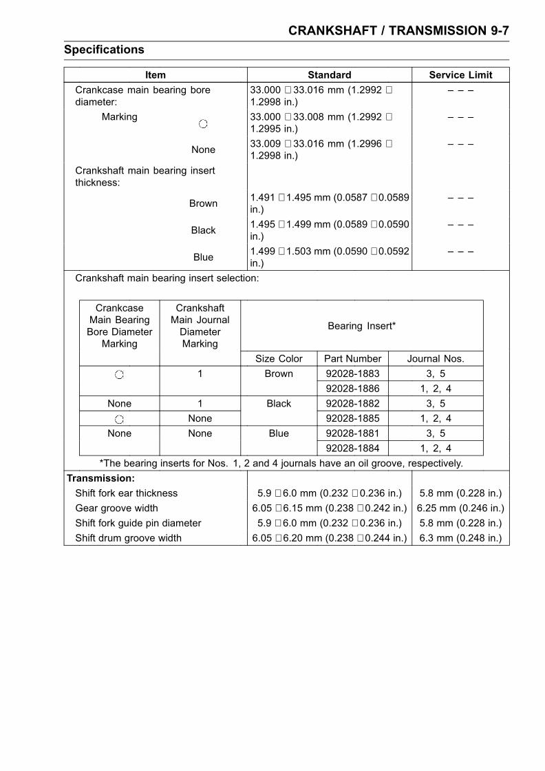
CRANKSHAFT / TRANSMISSION 9-7
Specifications
Item Standard Service Limit
Crankcase main bearing borediameter:
33.000 ∼ 33.016 mm (1.2992 ∼1.2998 in.)
– – –
Marking 33.000 ∼ 33.008 mm (1.2992 ∼1.2995 in.)
– – –
None33.009 ∼ 33.016 mm (1.2996 ∼1.2998 in.)
– – –
Crankshaft main bearing insertthickness:
Brown1.491 ∼ 1.495 mm (0.0587 ∼ 0.0589in.)
– – –
Black1.495 ∼ 1.499 mm (0.0589 ∼ 0.0590in.)
– – –
Blue1.499 ∼ 1.503 mm (0.0590 ∼ 0.0592in.)
– – –
Crankshaft main bearing insert selection:
CrankcaseMain BearingBore DiameterMarking
CrankshaftMain JournalDiameterMarking
Bearing Insert*
Size Color Part Number Journal Nos.
1 Brown 92028-1883 3, 5
92028-1886 1, 2, 4
None 1 Black 92028-1882 3, 5
None 92028-1885 1, 2, 4
None None Blue 92028-1881 3, 5
92028-1884 1, 2, 4
*The bearing inserts for Nos. 1, 2 and 4 journals have an oil groove, respectively.
Transmission:
Shift fork ear thickness 5.9 ∼ 6.0 mm (0.232 ∼ 0.236 in.) 5.8 mm (0.228 in.)
Gear groove width 6.05 ∼ 6.15 mm (0.238 ∼ 0.242 in.) 6.25 mm (0.246 in.)
Shift fork guide pin diameter 5.9 ∼ 6.0 mm (0.232 ∼ 0.236 in.) 5.8 mm (0.228 in.)
Shift drum groove width 6.05 ∼ 6.20 mm (0.238 ∼ 0.244 in.) 6.3 mm (0.248 in.)
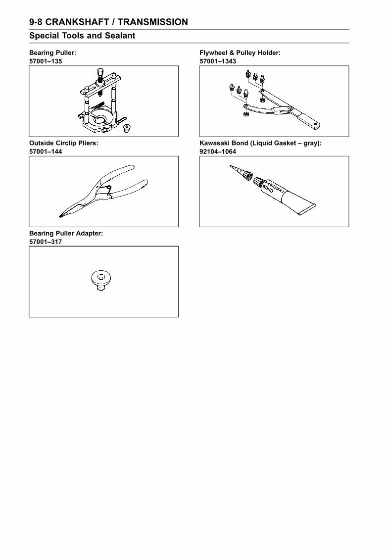
9-8 CRANKSHAFT / TRANSMISSION
Special Tools and Sealant
Bearing Puller:57001–135
Outside Circlip Pliers:57001–144
Bearing Puller Adapter:57001–317
Flywheel & Pulley Holder:57001–1343
Kawasaki Bond (Liquid Gasket – gray):92104–1064

CRANKSHAFT / TRANSMISSION 9-9
Crankcase Splitting
Crankcase Splitting
•Remove the engine (see Engine Removal/Installationchapter).
• Set the engine on a clean surface and hold the enginesteady while parts are being removed.
•Remove:Crankshaft Sensor (see Electrical System chapter)Clutch (see Clutch chapter)External Shift Mechanism (see External Shift Mecha-nism Removal)Starter Motor (see Electrical System chapter)Oil Pump (see Engine Lubrication System chapter)Alternator Rotor (see Electrical System chapter)Oil Filter (see Engine Lubrication System chapter)Oil Cooler (see Engine Lubrication System chapter)
If the crankshaft is to be removed, remove the pistons(see Engine Top End chapter).
• Hold the timing rotor [A] steady with the holder [B], andremove the timing rotor bolt [C] and the rotor.
Special Tool - Flywheel & Pulley Holder: 57001–1343
•Remove the upper crankcase bolts.First loosen the 6 mm bolts.6 mm Bolts [A]7 mm Bolts [B]
• Turn the engine upside down.•Remove the oil pan, oil screen and oil pipes (see EngineLubrication System chapter).
• Remove the lower crankcase bolts and brackets.First loosen the 6 mm bolts.6 mm Bolts [A]7 mm Bolts [B]
• Tap lightly around the crankcase mating surface with aplastic mallet, and split the crankcase. Take care not todamage the crankcase.
Crankcase Assembly
NOTEThe upper and lower crankcase halves are machinedat the factory in the assembled state, so the crankcasehalves must be replaced as a set.
•With a high-flash point solvent, clean off the mating sur-faces of the crankcases halves and wipe dry.
•Using compressed air, blow out the oil passages in thecrankcase halves.

9-10 CRANKSHAFT / TRANSMISSION
Crankcase Splitting
•Apply silicone sealant to the breather plate mating surface[A] 1 to 1.5 mm (0.04 to 0.06 in.) thick, and wait untilsealant dries.
Sealant - Three Bond #1207B and/or equivalent
• Install the breather plate [B], and apply a non-permanentlocking agent to the threads and tighten the bolts [A].
Torque - Breather Plate Bolts: 9.8 N·m (1.0 kgf·m, 87 in·lb)
• Install the oil jet nozzles [A].• Apply a non-permanent locking agent to the threads of oiljet nozzle bolts.
• Tighten:Torque - Oil Jet Nozzle Bolts: 6.9 N·m (0.70 kgf·m, 61 in·lb)
• Install:Crankshaft and Connecting RodsCamshaft Chain [A]Transmission Shaft and GearsDowel Pins [B]Shift DrumShift Forks and Shift Rods
•Before fitting the lower case on the upper case, check thefollowing.Be sure to hang the camshaft chain on the crankshaft.Check to see that the shift drum and transmission gearsare in the neutral position.

CRANKSHAFT / TRANSMISSION 9-11
Crankcase Splitting
•Apply liquid gasket [A] to the mating surface of the lowercrankcase half.
Sealant - Kawasaki Bond (Liquid Gasket – gray):92104–1064
NOTEEspecially, apply a sealant carefully so that it shall befilled up on the grooves.
CAUTION
Do not apply silicone sealant around the crankshaftmain bearing inserts, and oil passage holes.
•Tighten the lower crankcase bolts, using the followingsteps.
• The 7 mm bolts shown [A] has a copper plated washer.Replace it with a new one.Apply molybdenum disulfide oil to both side of the 7 mmbolt washers, bolt threads and seating surfaces of thewashers and bolts.Following the sequence numbers on the lower crankcasehalf, tighten the 7 mm bolts [1 ∼ 10].Torque - Crankcase 7 mm Bolts: 24 N·m (2.4 kgf·m, 18 ft·lb)
Install the clamp [B] and tighten the 7 mm bolts [C].
Torque - Crankcase (L38 mm) 7 mm Bolts: 27 N·m (2.8kgf·m, 20 ft·lb)
Tighten the 6 mm bolts [D].
Torque - Crankcase 6 mm Bolts: 12 N·m (1.2 kgf·m, 104in·lb)
•Turn the crankcase assembly up.• Tighten the upper crankcase bolts in the order listed.Install the clamp [A].Torque - Crankcase 7 mm Bolts [B]: 20 N·m (2.0 kgf·m, 14.5
ft·lb)Crankcase 6 mm Bolts [C]: 12 N·m (1.2 kgf·m, 104in·lb)
•After tightening all crankcase bolts, check the followingitems.Crankshaft and transmission shafts turn freely.While spinning the output shaft, gears shift smoothly fromthe 1st to 6th gear, and 6th to 1st.When the output shaft stays still, the gear can not beshifted to 2nd gear or other higher gear positions.
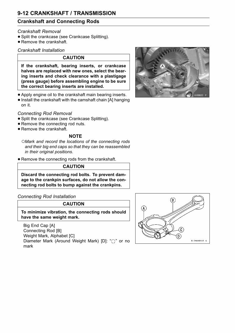
9-12 CRANKSHAFT / TRANSMISSION
Crankshaft and Connecting Rods
Crankshaft Removal
•Split the crankcase (see Crankcase Splitting).•Remove the crankshaft.Crankshaft Installation
CAUTION
If the crankshaft, bearing inserts, or crankcasehalves are replaced with new ones, select the bear-ing inserts and check clearance with a plastigage(press gauge) before assembling engine to be surethe correct bearing inserts are installed.
•Apply engine oil to the crankshaft main bearing inserts.• Install the crankshaft with the camshaft chain [A] hangingon it.
Connecting Rod Removal
•Split the crankcase (see Crankcase Splitting).•Remove the connecting rod nuts.•Remove the crankshaft.
NOTEMark and record the locations of the connecting rodsand their big end caps so that they can be reassembledin their original positions.
•Remove the connecting rods from the crankshaft.
CAUTION
Discard the connecting rod bolts. To prevent dam-age to the crankpin surfaces, do not allow the con-necting rod bolts to bump against the crankpins.
Connecting Rod Installation
CAUTION
To minimize vibration, the connecting rods shouldhave the same weight mark.
Big End Cap [A]Connecting Rod [B]Weight Mark, Alphabet [C]Diameter Mark (Around Weight Mark) [D]: “ ” or nomark

CRANKSHAFT / TRANSMISSION 9-13
Crankshaft and Connecting Rods
CAUTION
If the connecting rods, big end bearing inserts, orcrankshaft are replaced with new ones, select thebearing insert and check clearance with a plasti-gage (press gauge) before assembling engine to besure the correct bearing inserts are installed.
CAUTION
The connecting rod bolts are designed to stretchwhen tightened. Never reuse them.
•Replace the connecting rod big end bolts and nuts withnew ones.
• Apply molybdenum disulfide oil to the inner surface of up-per and lower bearing inserts [A].
• Apply molybdenum disulfide oil to the threads [B] andseating surface [C] of the connecting rod nuts.
• Install the inserts so that their nails [D] are on the sameside and fit them into the recess of the connecting rod andcap.
CAUTION
Wrong application of oil and grease could causebearing damage.
When installing the inserts [A], be careful not to damagethe insert surface with the edge of the connecting rod [B]or the cap [C]. One way to install inserts is as follows.Installation [D] to CapInstallation [E] to Connecting RodPush [F]Spare Dowel Pin [G]Connecting Rod Bolts [H]
The connecting rod big end is bolted using the “plasticregion fastening method”.This method precisely achieves the needed clampingforce without exceeding it unnecessarily, allowing theuse of thinner, lighter bolts further decreasing connectingrod weight.There are two types of the plastic region fastening. Oneis a bolt length measurement method and other is a tight-ening torque method. Observe one of the following two,but the bolt length measurement method is preferable be-cause this is a more reliable way to tighten the big endnuts.

9-14 CRANKSHAFT / TRANSMISSION
Crankshaft and Connecting Rods
(1) Bolt Length Measurement Method
•Be sure to clean the bolts, nuts, and connecting rodsthoroughly with high-flash point solvent, because the newconnecting rods, bolts, and nuts are treated with an anti-rust solution.
WARNINGClean the bolts, nuts, and connecting rods in a well-ventilated area, and take care that there is no sparkor flame anywhere near the working area. This in-cludes any appliance with a pilot light. Because ofthe danger of highly flammable liquids, do not usegasoline or low-flash point solvents to clean them.
CAUTION
Immediately dry the bolts and nuts with com-pressed air after cleaning.Clean and dry the bolts and nuts completely.
• Install new bolts in reused connecting rods.•Dent both bolt head and bolt tip with a punch as shown.• Before tightening, use a point micrometer to measure thelength of new connecting rod bolts and record the valuesto find the bolt stretch.Connecting Rod [A]Dent here with a punch [B]Nuts [C]Fit micrometer pins into dents [D]
• Tighten the big end nuts until the bolt elongation reachesthe specified length.
•Check the length of the connecting rod bolts.If the stretch is more than the usable range, the bolt hasstretched too much. An overlongated bolt may break inuse.
Bolt Length Bolt Lengthafter tightening
–before tightening
= Stretch
Usable Range of Connecting Rod Bolt Stretch –
0.18 ∼ 0.28 mm (0.007 ∼ 0.011 in.)

CRANKSHAFT / TRANSMISSION 9-15
Crankshaft and Connecting Rods
(2) Tightening Torque Method
• If you don’t have a point micrometer, you may tighten thenuts using the “Tightening Torque Method”.
• Be sure to clean the bolts, nuts, and connecting rodsthoroughly with high-flash point solvent, because the newconnecting rods, bolts, and nuts are treated with an anti-rust solution.
WARNINGClean the bolts, nuts, and connecting rods in a well-ventilated area, and take care that there is no sparkor flame anywhere near the working area. This in-cludes any appliance with a pilot light. Because ofthe danger of highly flammable liquids, do not usegasoline or low-flash point solvents to clean them.
CAUTION
Immediately dry the bolts and nuts with com-pressed air after cleaning.Clean and dry the bolts and nuts completely.
•Apply a small amount of molybdenum disulfide oil to thethreads [A] and seating surface [B] of the connecting rodnuts.
• First, tighten the nuts to the specified torque. See thetable below
•Next, tighten the nuts 120° more.Mark [A] the connecting rod big end caps and nuts so thatnuts can be turned 120° [B] properly.
Connecting Bolt, Nut Torque + Angle
Rod Assy N·m (kgf·m, ft·lb)
NewUse the bolts attachedto new con-rod.
15 (1.5, 11) + 120°
Another new bolts andnuts
15 (1.5, 11) + 120°
UsedReplace the bolts andnuts with new ones
15 (1.5, 11) + 120°
CAUTION
Since the friction force of the eating surface andthread portion of new nuts is different from that ofused ones, the nut should be tightened with speci-fied torque.Be careful not to overtighten the nuts.

9-16 CRANKSHAFT / TRANSMISSION
Crankshaft and Connecting Rods
Crankshaft/Connecting Rod Cleaning
•After removing the connecting rods from the crankshaft,clean them with a high-flash point solvent.
• Blow the crankshaft oil passages with compressed air toremove any foreign particles or residue that may haveaccumulated in the passages.
Connecting Rod Bend
•Remove the connecting rod big end bearing inserts, andreinstall the connecting rod big end cap.
• Select an arbor [A] of the same diameter as the connect-ing rod big end, and insert the arbor through the connect-ing rod big end.
• Select an arbor of the same diameter as the piston pinand at least 100 mm (3.94 in.) long, and insert the arbor[B] through the connecting rod small end.
•On a surface plate, set the big-end arbor on V block [C].•With the connecting rod held vertically, use a heightgauge to measure the difference in the height of thearbor above the surface plate over a 100 mm (3.94 in.)length to determine the amount of connecting rod bend.If the connecting rod bend exceeds the service limit, theconnecting rod must be replaced.
Connecting Rod BendService Limit: TIR 0.2/100 mm (0.008/3.94 in.)
Connecting Rod Twist
•With the big-end arbor [A] still on V block [C], hold theconnecting rod horizontally and measure the amount thatthe arbor [B] varies from being paralleled with the surfaceplate over a 100 mm (3.94 in.) length of the arbor to de-termine the amount of connecting rod twist.If the connecting rod twist exceeds the service limit, theconnecting rod must be replaced.
Connecting Rod TwistService Limit: TIR 0.2/100 mm (0.008/3.94 in.)
Connecting Rod Big End Side Clearance
•Measure connecting rod big end side clearance [A].Insert a thickness gauge [B] between the big end and ei-ther crank web to determine clearance.
Connecting Rod Big End Side ClearanceStandard: 0.13 ∼ 0.33 mm (0.005 ∼ 0.013 in.)Service Limit: 0.5 mm (0.020 in.)
If the clearance exceeds the service limit, replace the con-necting rod with new one and then check the clearanceagain. If the clearance is too large after connecting rodreplacement, the crankshaft also must be replaced.

CRANKSHAFT / TRANSMISSION 9-17
Crankshaft and Connecting Rods
Connecting Rod Big End Bearing Insert/CrankpinWear
•Measure the bearing insert/crankpin [B] clearance withplastigage [A].
• Tighten the big end nuts to the specified torque (see Con-necting Rod Installation).
NOTEDo not move the connecting rod and crankshaft duringclearance measurement.
Connecting Rod Big End Bearing Insert/CrankpinClearanceStandard: 0.035 ∼ 0.064 mm (0.0014 ∼ 0.0025 in.)Service Limit: 0.10 mm (0.004 in.)
If the clearance is within the standard, no bearing replace-ment is required.If the clearance is between 0.065 mm (0.003 in.) andthe service limit 0.10 mm (0.004 in.), replace the bear-ing inserts [A] with inserts painted black [B]. Check in-sert/crankpin clearance with the plastigage. The clear-ance may exceed the standard slightly, but it must not beless than the minimum in order to avoid bearing seizure.If the clearance exceeds the service limit, measure thediameter of the crankpins.
Crankpin DiameterStandard: 29.984 ∼ 30.000 mm
(1.1805 ∼ 1.1811 in.)Service Limit: 29.97 mm (1.18 in.)
If any crankpin has worn past the service limit, replace thecrankshaft with a new one.If the measured crankpin diameters are not less than theservice limit, but do not coincide with the original diametermarkings on the crankshaft, make new marks on it.
Crankpin Diameter MarksNone 29.984 ∼ 29.994 mm (1.1805 ∼ 1.1809 in.)
29.995 ∼ 30.000 mm (1.1809 ∼ 1.1811 in.)
∆: Crankpin Diameter Marks, " " mark or no mark.

9-18 CRANKSHAFT / TRANSMISSION
Crankshaft and Connecting Rods
•Measure the connecting rod big end bore diameter, andmark each connecting rod big end in accordance with thebore diameter.
• Tighten the big end nuts to the specified torque (see Con-necting Rod Installation).
NOTEThe mark already on the big end should almost coincidewith the measurement because of little wear.
Connecting Rod Big End Bore Diameter MarksNone 33.000 mm ∼ 33.008 mm (1.2992 ∼ 1.2995 in.)
33.009 ∼ 33.016 mm (1.2996 ∼ 1.2998 in.)
Big End Cap [A]Connecting Rod [B]Weight Mark, Alphabet [C]Diameter Mark (Around Weight Mark) [D]: “ ” or nomark
•Select the proper bearing insert [A] in accordance with thecombination of the connecting rod and crankshaft coding.Size Color [B]
Bearing InsertCon-rod Big EndBore Diameter
Marking
CrankpinDiameterMarking Size Color Part Number
None Pink 92028–1880
None NoneBrown 92028–1879
None Black 92028–1878
• Install the new inserts in the connecting rod and checkinsert/crankpin clearance with the plastigage.
Crankshaft Side Clearance
• Insert a thickness gauge [A] between the crankcase mainbearing and the crank web at the No. 2 journal [B] todetermine clearance.If the clearance exceeds the service limit, replace thecrankcase halves as a set.
NOTEThe upper and lower crankcase halves are machinedat the factory in the assembled state, so the crankcasehalves must be replaced as a set.
Crankshaft Side ClearanceStandard: 0.05 ∼ 0.15 mm (0.002 ∼ 0.006 in.)Service Limit: 0.35 mm (0.014 in.)

CRANKSHAFT / TRANSMISSION 9-19
Crankshaft and Connecting Rods
Crankshaft Runout
•Measure the crankshaft runout.If the measurement exceeds the service limit, replace thecrankshaft.
Crankshaft RunoutStandard: TIR 0.02 mm (0.0008 in.) or less
Service Limit: TIR 0.05 mmm (0.002 in.)
Crankshaft Main Bearing Insert/Journal Wear
•Using a plastigage (press gauge) [A], measure the bear-ing insert/journal [B] clearance.
NOTETighten the crankcase bolts to the specified torque (seeCrankcase Assembly).Do not turn the crankshaft during clearance measure-ment.Journal clearance less than 0.025 mm (0.001 in.) cannot bemeasured by plastigage, however, using genuineparts maintains the minimum standard clearance.
Crankshaft Main Bearing Insert/Journal ClearanceStandard: 0.031 ∼ 0.059 mm (0.0012 ∼ 0.0023 in.)Service Limit: 0.10 mm (0.0039 in.)
If the clearance is within the standard, no bearing replace-ment is required.If the clearance is between 0.059 mm (0.0023 in.) and theservice limit 0.09 mm (0.0035 in.), replace the bearing in-serts with inserts [A] painted blue [B]. Check insert/journalclearance with the plastigage. The clearancemay exceedthe standard slightly, but it must not be less than the min-imum in order to avoid bearing seizure.If the clearance exceeds the service limit, measure thediameter of the crankshaft main journal.
Crankshaft Main Journal DiameterStandard: 29.984 ∼ 30.000 mm (1.1805 ∼ 1.1811
in.)Service Limit: 29.96 mm (1.18 in.)
If any journal has worn past the service limit, replace thecrankshaft with a new one.If the measured journal diameters are not less than theservice limit, but do not coincide with the original diametermarkings on the crankshaft, make new marks on it.
Crankshaft Main Journal Diameter MarksNone 29.984 ∼ 29.994 mm (1.1805 ∼ 1.1809 in.)1 29.995 ∼ 30.000 mm (1.1809 ∼ 1.1811 in.)
: Crankshaft Main Journal Diameter Marks, "1" mark orno mark.

9-20 CRANKSHAFT / TRANSMISSION
Crankshaft and Connecting Rods
•Measure the main bearing bore diameter, and mark theupper crankcase half in accordance with the bore diame-ter.A: Crankcase Main Bearing Bore Diameter Marks, " "mark or no mark.
NOTETighten the crankcase bolts to the specified torque (seeCrankcase Assembly).The mark already on the upper crankcase half shouldalmost coincide with the measurement.
Crankcase Main Bearing Bore Diameter Marks33.000 ∼ 33.008 mm (1.2992 ∼ 1.2995 in.)
None 33.009 ∼ 33.016 mm (1.2996 ∼ 1.2998 in.)
•Select the proper bearing insert [A] in accordance with thecombination of the crankcase and crankshaft coding.Size Color [B]
Bearing Insert*Crankcase MainBearing Bore
Diameter Marking
Crankshaft MainJournal Diameter
Marking Size Color Part Number Journal Nos.
1 Brown 92028-1883 3, 5
92028-1886 1, 2, 4
None 1 Black 92028-1882 3, 5
None 92028-1885 1, 2, 4
None None Blue 92028-1881 3, 5
92028-1884 1, 2, 4
*The bearing inserts for Nos. 1, 2 and 4 journals have an oil groove, respectively.
• Install the new inserts in the crankcase halves and checkinsert/journal clearance with the plastigage.
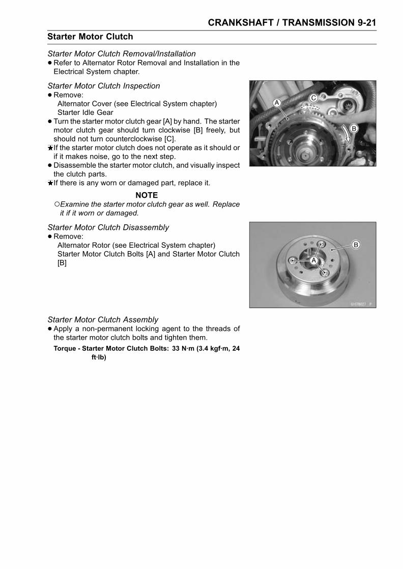
CRANKSHAFT / TRANSMISSION 9-21
Starter Motor Clutch
Starter Motor Clutch Removal/Installation
•Refer to Alternator Rotor Removal and Installation in theElectrical System chapter.
Starter Motor Clutch Inspection
•Remove:Alternator Cover (see Electrical System chapter)Starter Idle Gear
• Turn the starter motor clutch gear [A] by hand. The startermotor clutch gear should turn clockwise [B] freely, butshould not turn counterclockwise [C].If the starter motor clutch does not operate as it should orif it makes noise, go to the next step.
•Disassemble the starter motor clutch, and visually inspectthe clutch parts.If there is any worn or damaged part, replace it.
NOTEExamine the starter motor clutch gear as well. Replaceit if it worn or damaged.
Starter Motor Clutch Disassembly
•Remove:Alternator Rotor (see Electrical System chapter)Starter Motor Clutch Bolts [A] and Starter Motor Clutch[B]
Starter Motor Clutch Assembly
•Apply a non-permanent locking agent to the threads ofthe starter motor clutch bolts and tighten them.
Torque - Starter Motor Clutch Bolts: 33 N·m (3.4 kgf·m, 24ft·lb)

9-22 CRANKSHAFT / TRANSMISSION
Transmission
Shift Pedal Removal
•Mark the position of the shift lever on the shift shaft sothat it can be installed later in the same position.
•Remove the shift lever and shift pedal.Shift Pedal Installation
• Install the shift pedal [A] so that the distance between thecenter of the shift pedal and the center line of the shift rod[B] is 10 ∼ 15 mm (0.39 ∼ 0.59 in.) by loosening the frontand rear locknuts [C] and turning the rod.
NOTEThe locknut next to the groove [D] of the rod has left-hand threads.
If necessary, adjust the pedal position from the standardposition to suit you as follows.
• Loosen the front and rear rod locknuts.• Turn the rod to adjust the pedal position.• Tighten the locknuts securely.External Shift Mechanism Removal
•Drain the engine oil (see Cooling System in the PeriodicMaintenance chapter).
• Remove:Shift Pedal (see Shift Pedal Removal)Clutch (see Clutch chapter)Bolts [A], Oil Pipe Holders [B], Oil Pipe [C] and O-ring
•Remove:Shift Shaft [A]Bolt [B]Gear Positioning Lever [C] and SpringCollar
External Shift Mechanism Installation
• Install the gear positioning lever [A] as shown, and tightenthe bolt.
Springs [B] Collar [C]Bolt [D]
Torque - Gear Positioning Lever Bolt: 9.8 N·m (1.0 kgf·m,87 in·lb)
•Tighten the oil pipe holder bolts.Torque - Oil Pipe Holder Bolts: 12 N·m (1.2 kgf·m, 104 in·lb)

CRANKSHAFT / TRANSMISSION 9-23
Transmission
External Shift Mechanism Inspection
•Examine the shift shaft [A] for any damage.If the shaft is bent, straighten or replace it.If the serration are damaged, replace the shaft.If the springs [B] [C] are damaged in any way, replacethem.If the shift mechanism arm [D] is damaged in any way,replace the arm.
•Check the return spring pin [A] is not loose.If it is loose, unscrew it, apply a non-permanent lockingagent to the threads, and tighten it.
Torque - Shift Shaft Return Spring Pin: 28 N·m (2.9 kgf·m,21 ft·lb)
•Check the gear positioning lever [B] and it’s spring forbreaks or distortion.If the lever or spring are damaged in any way, replacethem.
•Visually inspect the shift drum cam [C].If they are badly worn or if they show any damage, replaceit.
Transmission Shaft Removal
•Split the crankcase (see Crankcase Splitting).•Remove the drive shaft [A] and output shaft [B].
Transmission Shaft Installation
•Check to see that the set pins [A] and set rings [B] are inplace.

9-24 CRANKSHAFT / TRANSMISSION
Transmission
• Install the drive shaft and output shaft into the uppercrankcase half.
• Apply engine oil to the sliding surfaces of the gears andbearings.The bearing set pins and rings must match properly withthe holes or grooves in the bearing outer races. Whenthey are properly matched, there is no clearance betweenthe crankcase and the bearing outer races [A].
Transmission Shaft Disassembly
•Remove the transmission shafts (see Transmission ShaftRemoval).
• Remove the circlips, and disassemble the transmissionshafts.
Special Tool - Outside Circlip Pliers: 57001-144
•The 5th gear [A] on the output shaft has three steel ballsassembled into it for the positive neutral finder mecha-nism. Remove the 5th gear.Set the output shaft in a vertical position holding the 3rdgear [B].Spin the 5th gear quickly [C] and pull it off upward.•Remove the ball bearing [A] and/or collar from eachshafts.
Special Tools - Bearing Puller: 57001-135 [B]Bearing Puller Adapter: 57001-317 [C]
•Discard the bearing.
Transmission Shaft Assembly
•Apply engine oil to the ball bearing and shaft.• Install the ball bearing on the drive shaft [A] with thegroove [B] toward the clutch side using the steering stembearing driver.
• Install the ball bearing and collar on the output shaft [C]using the steering stem bearing driver.
Special Tool - Steering Stem Bearing Driver: 57001–382

CRANKSHAFT / TRANSMISSION 9-25
Transmission
• Install the gear bushing [A] on the shafts with their oilholes [B] aligned.
• The drive shaft gears can be recognized by size: the gearwith the smallest diameter is 1st gear, and the largest oneis 6th gear. Be sure that all parts are put back in the cor-rect sequence and all circlips and washers are properly inplace.
• Install the 3rd/4th gear onto the drive shaft with their holesaligned.
• The output shaft gears can be recognized by size: thegear with the largest diameter is 1st gear, and the small-est one is 6th gear. Be sure that all parts are put backin the correct sequence and all circlips and washers areproperly in place.
• Install the 5th and 6th gears onto the output shaft withtheir holes aligned.
•Replace any circlip that were removed with new ones.• Install the circlips [A] so that opening [B] is aligned with aspline groove [C].
•Check that each gear spins or slides freely on the trans-mission shafts without binding after assembly.
• Fit the steel balls into the 5th gear holes in the output shaftas shown.[A] Gear (5th)[B] Shaft[C] Steel Balls[D] Oil Holes
CAUTION
Do not apply grease to the steel balls to hold themin place. This will cause the positive neutral findermechanism to malfunction.
Check the ball-locking effect that the 5th gear does notcome out of the output shaft when moving it up and downby hand.
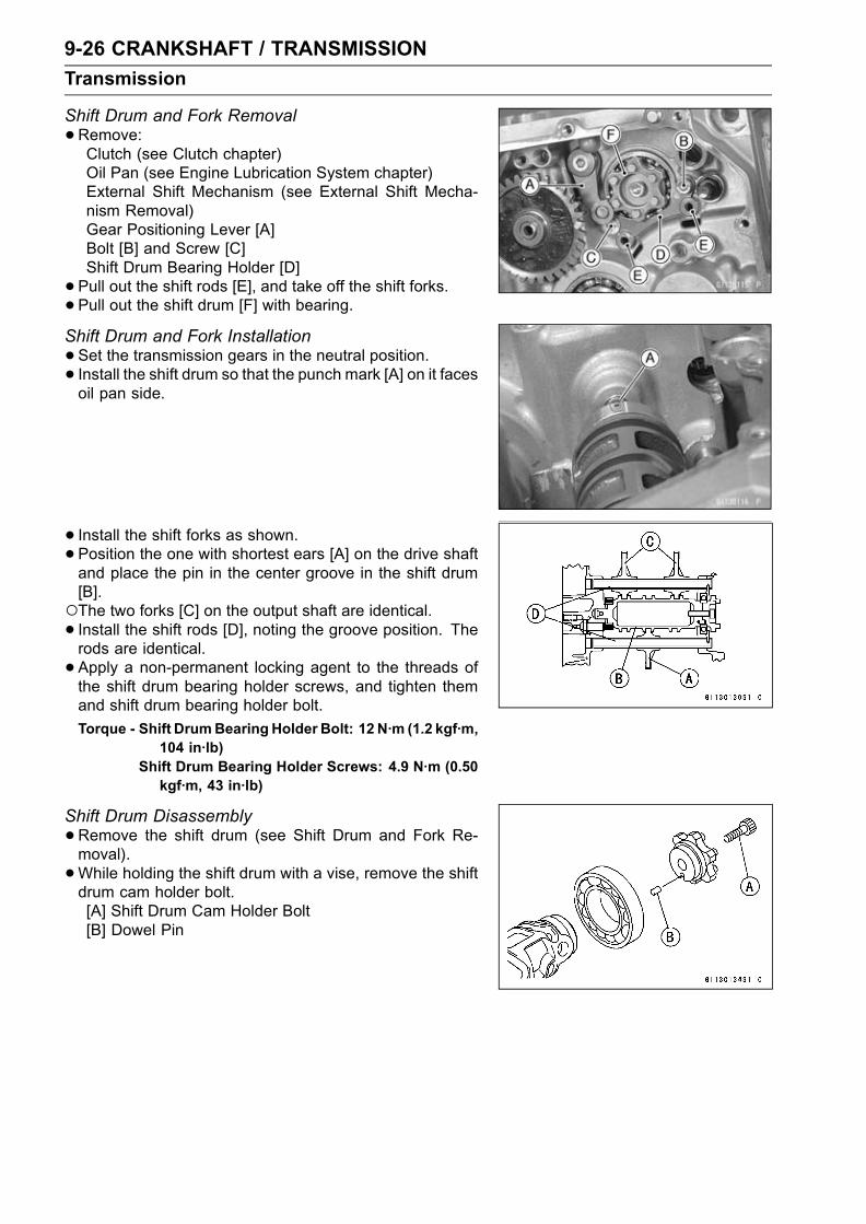
9-26 CRANKSHAFT / TRANSMISSION
Transmission
Shift Drum and Fork Removal
•Remove:Clutch (see Clutch chapter)Oil Pan (see Engine Lubrication System chapter)External Shift Mechanism (see External Shift Mecha-nism Removal)Gear Positioning Lever [A]Bolt [B] and Screw [C]Shift Drum Bearing Holder [D]
• Pull out the shift rods [E], and take off the shift forks.• Pull out the shift drum [F] with bearing.
Shift Drum and Fork Installation
•Set the transmission gears in the neutral position.• Install the shift drum so that the punch mark [A] on it facesoil pan side.
• Install the shift forks as shown.• Position the one with shortest ears [A] on the drive shaftand place the pin in the center groove in the shift drum[B].The two forks [C] on the output shaft are identical.• Install the shift rods [D], noting the groove position. Therods are identical.
• Apply a non-permanent locking agent to the threads ofthe shift drum bearing holder screws, and tighten themand shift drum bearing holder bolt.
Torque - Shift DrumBearing Holder Bolt: 12 N·m (1.2 kgf·m,104 in·lb)
Shift Drum Bearing Holder Screws: 4.9 N·m (0.50kgf·m, 43 in·lb)
Shift Drum Disassembly
•Remove the shift drum (see Shift Drum and Fork Re-moval).
•While holding the shift drum with a vise, remove the shiftdrum cam holder bolt.[A] Shift Drum Cam Holder Bolt[B] Dowel Pin

CRANKSHAFT / TRANSMISSION 9-27
Transmission
•Remove the holder [A] with a bearing puller [B].Special Tool - Bearing Puller: 57001–135
Shift Drum Assembly
•Be sure to install the dowel pin.• Apply a non-permanent locking agent to the threads ofthe shift drum cam holder bolt, and tighten it.
Torque - Shift Drum Cam Holder Bolt: 12 N·m (1.2 kgf·m,104 in·lb)
• Install the holder with a steering stem bearing driver sothat positioning hole [A] faces outside as shown.[B] Dowel Pin[C] 57°
Shift Fork Bending
•Visually inspect the shift forks, and replace any fork that isbent. A bent fork could cause difficulty in shifting, or allowthe transmission to jump out of gear when under power.90° [A]
Shift Fork/Gear Groove Wear
•Measure the thickness of the shift fork ears [A], and mea-sure the width [B] of the gear grooves.If the thickness of a shift fork ear is less than the servicelimit, the shift fork must be replaced.
Shift Fork Ear ThicknessStandard: 5.9 ∼ 6.0 mm (0.232 ∼ 0.236 in.)Service Limit: 5.8 mm (0.228 in.)
If the gear groove is worn over the service limit, the gearmust be replaced.
Gear Groove WidthStandard: 6.05 ∼ 6.15 mm (0.238 ∼ 0.242 in.)Service Limit: 6.25 mm (0.246 in.)

9-28 CRANKSHAFT / TRANSMISSION
Transmission
Shift Fork Guide Pin/Drum Groove Wear
•Measure the diameter of each shift fork guide pin [A], andmeasure the width [B] of each shift drum groove.If the guide pin on any shift fork is less than the servicelimit, the fork must be replaced.
Shift Fork Guide Pin DiameterStandard: 5.9 ∼ 6.0 mm (0.232 ∼ 0.236 in.)Service Limit: 5.8 mm (0.228 in.)
If any shift drum groove is worn over the service limit, thedrum must be replaced.
Shift Drum Groove WidthStandard: 6.05 ∼ 6.20 mm (0.238 ∼ 0.244 in.)Service Limit: 6.3 mm (0.248 in.)
Gear Dog and Gear Dog Hole Damage
•Visually inspect the gear dogs [A] and gear dog holes [B].Replace any damaged gears or gears with excessivelyworn dogs or dog holes.

CRANKSHAFT / TRANSMISSION 9-29
Transmission
1. 1st Gear2. 2nd Gear3. 3rd Gear4. 4th Gear5. 5th Gear6. 6th (Top) Gear7. Toothed Washer
8. Thrust Washer (Thin)9. Circlip10. Circlip11. Toothed Washer12. Thrust Washer13. Circlip14. Needle Bearing
15. Bearing Outer Race16. Bushing17. Ball Bearing18. Oil Seal19. Steel Ball


WHEELS / TIRES 10-1
10
Wheels / Tires
Table of Contents
Exploded View........................................................................................................................ 10-2Specifications ......................................................................................................................... 10-4Special Tools .......................................................................................................................... 10-5Wheels (Rims) ........................................................................................................................ 10-6
Front Wheel Removal ....................................................................................................... 10-6Front Wheel Installation .................................................................................................... 10-6Rear Wheel Removal........................................................................................................ 10-7Rear Wheel Installation..................................................................................................... 10-8Wheel Inspection .............................................................................................................. 10-9Axle Inspection.................................................................................................................. 10-9Balance Inspection............................................................................................................ 10-9Balance Adjustment .......................................................................................................... 10-10Balance Weight Removal.................................................................................................. 10-10Balance Weight Installation............................................................................................... 10-10
Tires........................................................................................................................................ 10-13Air Pressure Inspection/Adjustment.................................................................................. 10-13Tire Inspection .................................................................................................................. 10-13Tire Removal..................................................................................................................... 10-13Tire Installation.................................................................................................................. 10-13Tire Repair ........................................................................................................................ 10-15
Hub Bearing............................................................................................................................ 10-16Hub Bearing Removal....................................................................................................... 10-16Hub Bearing Installation.................................................................................................... 10-16Hub Bearing Inspection..................................................................................................... 10-17Hub Bearing Lubrication ................................................................................................... 10-17

10-2 WHEELS / TIRES
Exploded View

WHEELS / TIRES 10-3
Exploded View
TorqueNo. Fastener N·m kgf·m ft·lb Remarks
1 Front axle clamp bolts 20 2.0 14.52 Front axle nut 127 13.0 943 Rear axle nut 127 13.0 94
G: Apply grease.R: Replacement Parts
WL: Apply soap and water solution or rubber lubricant.
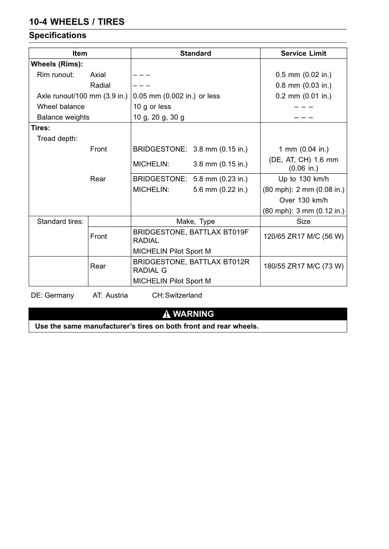
10-4 WHEELS / TIRES
Specifications
Item Standard Service Limit
Wheels (Rims):
Rim runout: Axial – – – 0.5 mm (0.02 in.)
Radial – – – 0.8 mm (0.03 in.)
Axle runout/100 mm (3.9 in.) 0.05 mm (0.002 in.) or less 0.2 mm (0.01 in.)
Wheel balance 10 g or less – – –
Balance weights 10 g, 20 g, 30 g – – –
Tires:
Tread depth:
Front BRIDGESTONE: 3.8 mm (0.15 in.) 1 mm (0.04 in.)
MICHELIN: 3.8 mm (0.15 in.)(DE, AT, CH) 1.6 mm
(0.06 in.)
Rear BRIDGESTONE: 5.8 mm (0.23 in.) Up to 130 km/h
MICHELIN: 5.6 mm (0.22 in.) (80 mph): 2 mm (0.08 in.)
Over 130 km/h
(80 mph): 3 mm (0.12 in.)
Standard tires: Make, Type Size
FrontBRIDGESTONE, BATTLAX BT019FRADIAL
120/65 ZR17 M/C (56 W)
MICHELIN Pilot Sport M
RearBRIDGESTONE, BATTLAX BT012RRADIAL G
180/55 ZR17 M/C (73 W)
MICHELIN Pilot Sport M
DE: Germany AT: Austria CH:Switzerland
WARNINGUse the same manufacturer’s tires on both front and rear wheels.

WHEELS / TIRES 10-5
Special Tools
Inside Circlip Pliers:57001–143
Bearing Driver Set:57001–1129
Jack:57001–1238
Bearing Remover Head, 25 × 28 :57001–1346
Bearing Remover Shaft, 13:57001–1377
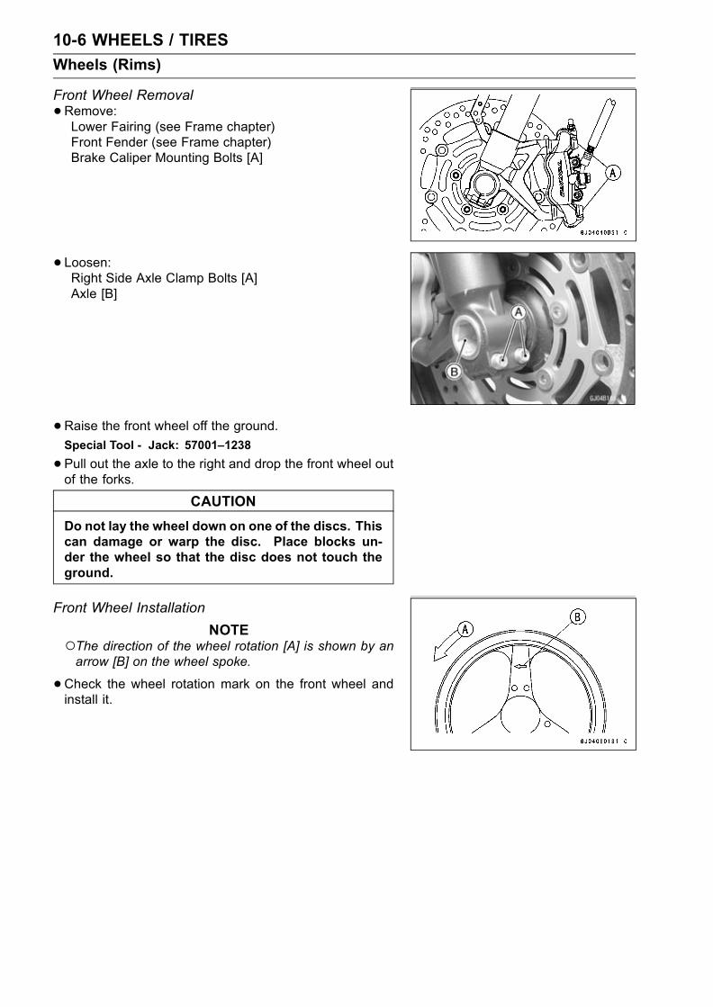
10-6 WHEELS / TIRES
Wheels (Rims)
Front Wheel Removal
•Remove:Lower Fairing (see Frame chapter)Front Fender (see Frame chapter)Brake Caliper Mounting Bolts [A]
• Loosen:Right Side Axle Clamp Bolts [A]Axle [B]
•Raise the front wheel off the ground.Special Tool - Jack: 57001–1238
•Pull out the axle to the right and drop the front wheel outof the forks.
CAUTION
Do not lay the wheel down on one of the discs. Thiscan damage or warp the disc. Place blocks un-der the wheel so that the disc does not touch theground.
Front Wheel Installation
NOTEThe direction of the wheel rotation [A] is shown by anarrow [B] on the wheel spoke.
•Check the wheel rotation mark on the front wheel andinstall it.
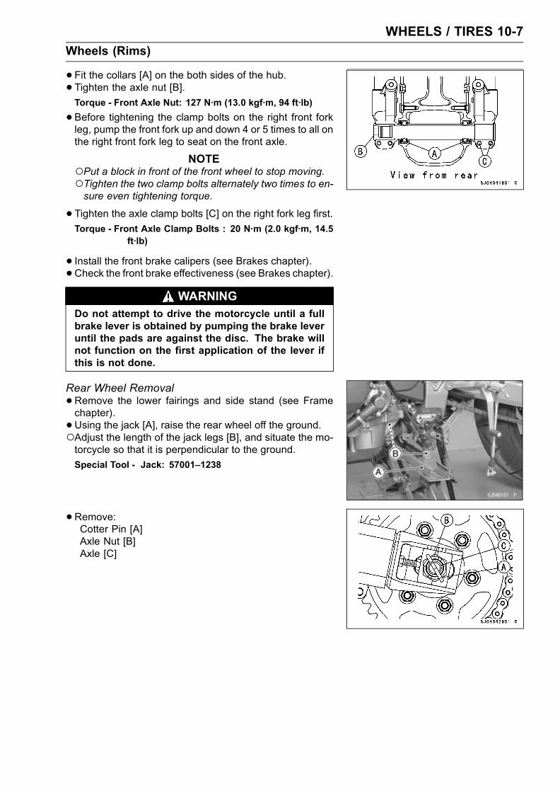
WHEELS / TIRES 10-7
Wheels (Rims)
•Fit the collars [A] on the both sides of the hub.• Tighten the axle nut [B].Torque - Front Axle Nut: 127 N·m (13.0 kgf·m, 94 ft·lb)
•Before tightening the clamp bolts on the right front forkleg, pump the front fork up and down 4 or 5 times to all onthe right front fork leg to seat on the front axle.
NOTEPut a block in front of the front wheel to stop moving.Tighten the two clamp bolts alternately two times to en-sure even tightening torque.
•Tighten the axle clamp bolts [C] on the right fork leg first.Torque - Front Axle Clamp Bolts : 20 N·m (2.0 kgf·m, 14.5
ft·lb)
• Install the front brake calipers (see Brakes chapter).• Check the front brake effectiveness (see Brakes chapter).
WARNINGDo not attempt to drive the motorcycle until a fullbrake lever is obtained by pumping the brake leveruntil the pads are against the disc. The brake willnot function on the first application of the lever ifthis is not done.
Rear Wheel Removal
•Remove the lower fairings and side stand (see Framechapter).
• Using the jack [A], raise the rear wheel off the ground.Adjust the length of the jack legs [B], and situate the mo-torcycle so that it is perpendicular to the ground.
Special Tool - Jack: 57001–1238
•Remove:Cotter Pin [A]Axle Nut [B]Axle [C]

10-8 WHEELS / TIRES
Wheels (Rims)
•Remove the rear caliper mounting bolts and rear caliper.•Remove the inner fender and chain cover.•Remove the drive chain [A] from the rear sprocket towardthe left.
•Move the rear wheel back and remove it.CAUTION
Do not lay the wheel on the ground with the discfacing down. This can damage or warp the disc.Place blocks under the wheel so that the disc doesnot touch the ground.
Rear Wheel Installation
•Engage the drive chain with the rear sprocket.• Install the caliper bracket [A] onto the swingarm stop [B].Insert the axle from the right side of the wheel, and tightenthe axle nut.
• Insert a new cotter pin [A].NOTE
When inserting the cotter pin, if the slots in the nut donot align with the cotter pin hole in the axle, tighten thenit clockwise [B] up to next alignment.It should be within 30 degree.Loosen once and tighten again when the slot goes pastthe nearest hole.
•Bend the cotter pin [A] over the nut [B].
Torque - Rear Axle Nut: 127 N·m (13.0 kgf·m, 94 ft·lb)
•Adjust the drive chain slack after installation (see FinalDrive in the Periodic Maintenance chapter).
• Install the rear caliper, chain cover and inner fender.•Check the rear brake effectiveness.
WARNINGDo not attempt to drive the motorcycle until a fullbrake pedal is obtained by pumping the brake pedaluntil the pads are against the disc. The brake willnot function on the first application of the pedal ifthis is not done.

WHEELS / TIRES 10-9
Wheels (Rims)
Wheel Inspection
•Raise the front/rear wheel off the ground.Special Tool - Jack: 57001–1238
•Spin the wheel lightly, and check for roughness or binding.If roughness or binding is found, replace the hub bearings.
• Inspect the wheel for small cracks, dents, bending, orwarp.If there is any damage to the wheel, replace the wheel.
• Remove the wheel, and support it without the tire by theaxle.
•Measure the rim runout, radial [A] and axial [B], with a dialgauge.If rim runout exceeds the service limit, check the hub bear-ings.If the problem is not due to the bearings, replace thewheel.
Rim RunoutService Limit: Axial 0.5 mm (0.02 in.)
Radial 0.8 mm (0.03 in.)
WARNINGNever attempt to repair a damaged wheel. If thereis any damage besides wheel bearings, the wheelmust be replaced to insure safe operational condi-tion.
Axle Inspection
•Remove the front and rear axles.• Visually inspect the front and rear axle for damages.If the axle is damaged or bent, replace it.
• Place the axle in V blocks that are 100 mm (3.94 in.) [A]apart, and set a dial gauge [B] on the axle at a pointhalfway between the blocks. Turn [C] the axle to mea-sure the runout. The difference between the highest andlowest dial readings is the amount of runout.If axle runout exceeds the service limit, replace the axle.
Axle Runout/100 mm (3.94 in.)Standard: 0.05 mm (0.002 in.) or less
Service Limit: 0.2 mm (0.01 in.)
Balance Inspection
•Remove the wheel.• Support the wheel so that it can be spun freely.• Spin the wheel lightly, and mark [A] the wheel at the topwhen the wheel stops.Repeat this procedure several times. If the wheel stopsof its own accord in various positions, it is well balanced.If the wheel always stops in one position, adjust the wheelbalance.
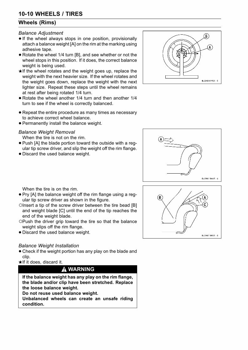
10-10 WHEELS / TIRES
Wheels (Rims)
Balance Adjustment
• If the wheel always stops in one position, provisionallyattach a balance weight [A] on the rim at themarking usingadhesive tape.
•Rotate the wheel 1/4 turn [B], and see whether or not thewheel stops in this position. If it does, the correct balanceweight is being used.If the wheel rotates and the weight goes up, replace theweight with the next heavier size. If the wheel rotates andthe weight goes down, replace the weight with the nextlighter size. Repeat these steps until the wheel remainsat rest after being rotated 1/4 turn.
•Rotate the wheel another 1/4 turn and then another 1/4turn to see if the wheel is correctly balanced.
•Repeat the entire procedure as many times as necessaryto achieve correct wheel balance.
• Permanently install the balance weight.Balance Weight RemovalWhen the tire is not on the rim.
• Push [A] the blade portion toward the outside with a reg-ular tip screw driver, and slip the weight off the rim flange.
•Discard the used balance weight.
When the tire is on the rim.
• Pry [A] the balance weight off the rim flange using a reg-ular tip screw driver as shown in the figure.Insert a tip of the screw driver between the tire bead [B]and weight blade [C] until the end of the tip reaches theend of the weight blade.Push the driver grip toward the tire so that the balanceweight slips off the rim flange.
•Discard the used balance weight.
Balance Weight Installation
•Check if the weight portion has any play on the blade andclip.If it does, discard it.
WARNINGIf the balance weight has any play on the rim flange,the blade and/or clip have been stretched. Replacethe loose balance weight.Do not reuse used balance weight.Unbalanced wheels can create an unsafe ridingcondition.

WHEELS / TIRES 10-11
Wheels (Rims)
•Lubricate the balance weight blade, tire bead, and rimflange with a soap and water solution or rubber lubricant.This helps the balance weight slip onto the rim flange.
CAUTION
Never lubricate with engine oil or petroleum distil-lates because they will deteriorate the tire.
•When required total weight exceeds 20g (0.71 oz), installthe balance weight at both sides of rim flange as shown.
Weight SelectionRequired TotalWeight One Side [A] Other Side [B]
20g (0.71 oz) 10g (0.35 oz) 10g (0.35 oz)
30g (1.06 oz) 20g (0.71 oz) 10g (0.35 oz)
40g (1.41 oz) 20g (0.71 oz) 20g (0.71 oz)
50g (1.76 oz) 30g (1.06 oz) 20g (0.71 oz)
60g (2.12 oz) 30g (1.06 oz) 30g (1.06 oz)
70g (2.47 oz)20g + 20g
(0.71oz + 0.71 oz)30g (1.06 oz)
80g (2.82 oz)20g + 20g
(0.71oz + 0.71 oz)20g + 20g
(0.71oz + 0.71 oz)
90g (3.17 oz)20g + 30g
(0.71 oz + 1.06 oz)20g + 20g
(0.71oz + 0.71 oz)
Balance Weight
Part Number Weight
41075-1014 10g (0.35 oz)
41075-1015 20g (0.71 oz)
41075-1016 30g (1.06 oz)
NOTEBalance weights are available from Kawasaki dealersin 10, 20, and 30 gram (0.35 oz, 0.71 oz, and 1.06 oz)sizes. An imbalance of less than 10 grams (0.35 oz) willnot usually affect running stability.Do not use four or more balance weight (more than 90gram). If the wheel requires an excess balance weight,disassemble the wheel to find the cause.
• Install the balance weight on the rim.Slip the weight on the rim flange by pushing or lightly ham-mering the weight in the direction shown in the figure.
Push or hammer [A] Tire Bead [C]Rim Flange [B] Blade [D]

10-12 WHEELS / TIRES
Wheels (Rims)
Check that the blade [A] and weight [B] seat fully on therim flange [C], and that the clip [D] is hooked over the rimridge [E] and reaches rim flat portion.

WHEELS / TIRES 10-13
Tires
Air Pressure Inspection/AdjustmentRefer to the Wheels/Tires in the Periodic Maintenancechapter.
Tire InspectionRefer to the Wheels/Tires in the Periodic Maintenancechapter.
Tire Removal
•Remove:Wheel (see this chapter)Disc(s)Valve Core (let out the air)
• To maintain wheel balance, mark the valve stem positionon the tire with chalk so that the tire can be reinstalled inthe same position.Chalk Mark or Yellow Mark [A]Air Valve [B]Align [C]
• Lubricate the tire beads and rim flanges on both sides witha soap and water solution or rubber lubricant. This helpsthe tire beads slip off the rim flanges.
CAUTION
Never lubricate with engine oil or petroleum distil-lates because they will deteriorate the tire.
•Remove the tire from the rim using a suitable commer-cially available tire changer.
NOTEThe tires cannot be removed with hand tools becausethey fit the rims too tightly.
Tire Installation
WARNINGUse the same manufacture’s on both front and rearwheels.
• Inspect the rim and tire, and replace them if necessary.•Clean the sealing surfaces of the rim and tire, and smooththe sealing surfaces of the rim with a fine emery cloth ifnecessary.
•Remove the air valve and discard it.CAUTION
Replace the air valve whenever the tire is replaced.Do not reuse the air valve.
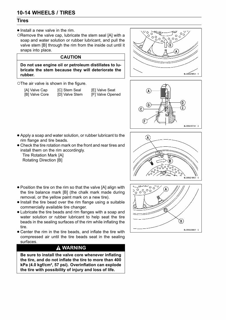
10-14 WHEELS / TIRES
Tires
• Install a new valve in the rim.Remove the valve cap, lubricate the stem seal [A] with asoap and water solution or rubber lubricant, and pull thevalve stem [B] through the rim from the inside out until itsnaps into place.
CAUTION
Do not use engine oil or petroleum distillates to lu-bricate the stem because they will deteriorate therubber.
The air valve is shown in the figure.[A] Valve Cap [C] Stem Seal [E] Valve Seat[B] Valve Core [D] Valve Stem [F] Valve Opened
•Apply a soap and water solution, or rubber lubricant to therim flange and tire beads.
•Check the tire rotation mark on the front and rear tires andinstall them on the rim accordingly.Tire Rotation Mark [A]Rotating Direction [B]
• Position the tire on the rim so that the valve [A] align withthe tire balance mark [B] (the chalk mark made duringremoval, or the yellow paint mark on a new tire).
• Install the tire bead over the rim flange using a suitablecommercially available tire changer.
• Lubricate the tire beads and rim flanges with a soap andwater solution or rubber lubricant to help seat the tirebeads in the sealing surfaces of the rim while inflating thetire.
•Center the rim in the tire beads, and inflate the tire withcompressed air until the tire beads seat in the sealingsurfaces.
WARNINGBe sure to install the valve core whenever inflatingthe tire, and do not inflate the tire to more than 400kPa (4.0 kgf/cm², 57 psi). Overinflation can explodethe tire with possibility of injury and loss of life.

WHEELS / TIRES 10-15
Tires
•Check to see that the rim lines [A] on both sides of the tiresidewalls are parallel with the rim flanges.If the rim flanges and tire sidewall rim lines are not parallel,remove the valve core.
• Lubricate the rim flanges and tire beads.
• Install the valve core and inflate the tire again.• After the tire beads seat in the rim flanges, check for airleakage.Inflate the tire slightly above standard inflation.Use a soap and water solution or submerge the tire, andcheck for bubbles that would indicate leakage.
• Adjust the air pressure to the specified pressure (see TireInspection).
• Install the air valve cap.• Install the brake disc(s) so that the marked side faces out(see Brakes chapter).
• Adjust the wheel balance (see Balance Adjustment).Tire RepairCurrently two types of repair for tubeless tires have come
into wide use. One type is called a temporary (external) re-pair which can be carried out without removing the tire fromthe rim, and the other type is called permanent (internal)repair which requires tire removal. It is generally under-stood that higher running durability is obtained by perma-nent (internal) repairs than by temporary (external) ones.Also, permanent (internal) repairs have the advantage ofpermitting a thorough examination for secondary damagenot visible from external inspection of the tire. For thesereasons, Kawasaki does not recommend temporary (exter-nal) repair. Only appropriate permanent (internal) repairsare recommended. Repair methods may vary slightly frommake to make. Follow the repair methods indicated by themanufacturer of the repair tools and materials so that saferesults can be obtained.

10-16 WHEELS / TIRES
Hub Bearing
Hub Bearing Removal
•Remove the wheel, and take out the following.CollarsCoupling (out of rear hub)Grease SealsCirclips [A] (Rear Hub only)
Special Tool - Inside Circlip Pliers: 57001–143 [B]
•Use the bearing remover to remove the hub bearing [A].CAUTION
Do not lay the wheel on the ground with the discfacing down. This can damage or warp the disc.Place blocks under the wheel so that the disc doesnot touch the ground.
Special Tools - Bearing Remover Shaft, 13: 57001–1377[B]
Bearing Remover Head, 25 × 28:57001–1346 [C]
Hub Bearing Installation
•Before installing the wheel bearings, blow any dirt or for-eign particles out of the hub with compressed air to pre-vent contamination of the bearings.
•Replace the bearings with new ones.NOTE
Install the bearings so that the marked side faces out.• Install the bearings by using the bearing driver set whichdoes not contact the bearing inner race.
• Press in each right the bearing [A] until they are bottomed.Special Tool - Bearing Driver Set: 57001–1129 [B]
•Replace the circlips with new ones (rear hub only).Special Tool - Inside Circlip Pliers: 57001–143
•Replace the grease seals with new ones.• Press in the grease seals [A] so that the seal surface isflush [B] with the end of the hole.Apply high temperature grease to the grease seal lips.Special Tool - Bearing Driver Set: 57001–1129 [C]

WHEELS / TIRES 10-17
Hub Bearing
Hub Bearing InspectionSince the hub bearings are made to extremely close tol-
erances, the clearance can not normally be measured.
NOTEDo not remove any bearings for inspection. If any bear-ings are removed, they will need to be replaced withnew ones.
•Turn each bearing in the hub back and forth [A] whilechecking for plays, roughness, or binding.If bearing play, roughness, or binding is found, replacethe bearing.
• Examine the bearing seal [B] for tears or leakage.If the seal is torn or is leaking, replace the bearing.
Hub Bearing Lubrication
NOTESince the hub bearings are packed with grease andsealed, lubrication is not required.


FINAL DRIVE 11-1
11
Final Drive
Table of Contents
Exploded View ....................................................................................................................... 11-2Specifications ........................................................................................................................ 11-4Special Tools .......................................................................................................................... 11-5Drive Chain............................................................................................................................. 11-6
Drive Chain Slack Inspection ............................................................................................ 11-6Drive Chain Slack Adjustment .......................................................................................... 11-6Wheel Alignment Inspection/Adjustment .......................................................................... 11-6Drive Chain Wear Inspection ............................................................................................ 11-6Drive Chain Lubrication..................................................................................................... 11-6Drive Chain Removal ........................................................................................................ 11-6Drive Chain Installation ..................................................................................................... 11-6Drive Chain Replacement ................................................................................................. 11-6
Sprocket, Coupling ................................................................................................................. 11-10Engine Sprocket Removal ................................................................................................ 11-10Engine Sprocket Installation ............................................................................................. 11-10Rear Sprocket Removal.................................................................................................... 11-11Rear Sprocket Installation................................................................................................. 11-11Coupling Installation.......................................................................................................... 11-11Coupling Bearing Removal ............................................................................................... 11-11Coupling Bearing Installation ............................................................................................ 11-12Coupling Bearing Inspection ............................................................................................. 11-12Coupling Bearing Lubrication............................................................................................ 11-12Coupling Damper Inspection............................................................................................. 11-12Sprocket Wear Inspection................................................................................................. 11-13Rear Sprocket Warp Inspection ........................................................................................ 11-13

11-2 FINAL DRIVE
Exploded View

FINAL DRIVE 11-3
Exploded View
TorqueNo. Fastener N·m kgf·m ft·lb Remarks
1 Speed sensor bolt 3.9 0.40 35 in·lb L2 Engine sprocket cover bolts 6.9 0.70 61 in·lb3 Engine sprocket nut 125 13.0 92 MO4 Rear axle nut 127 13.0 945 Rear sprocket nuts 59 6.0 43
6. Drive chain joint (ZX636–B2 ∼ )G: Apply grease.HO: Apply heavy oil.L: Apply a non-permanent locking agent.
MO: Apply molybdenum disulfide oil solution.R: Replacement parts.

11-4 FINAL DRIVE
Specifications
Item Standard Service Limit
Drive Chain:
Standard chain
Make ENUMA – – –
Type EK520MVXL, Endless – – –
Link 108 links – – –
Sprockets:
Rear sprocket warp 0.4 mm (0.016 in.) or less 0.5 mm (0.02 in.)

FINAL DRIVE 11-5
Special Tools
Inside Circlip Pliers:57001–143
Bearing Driver Set:57001–1129
Jack:57001–1238

11-6 FINAL DRIVE
Drive Chain
Drive Chain Slack InspectionRefer to the Final Drive in the Periodic Maintenance chap-ter.
Drive Chain Slack AdjustmentRefer to the Final Drive in the Periodic Maintenance chap-ter.
Wheel Alignment Inspection/AdjustmentRefer to the Final Drive in the Periodic Maintenance chap-ter.
Drive Chain Wear InspectionRefer to the Final Drive in the Periodic Maintenance chap-ter.
Drive Chain LubricationRefer to the Final Drive in the Periodic Maintenance chap-ter.
Drive Chain Removal
•Remove:Chain Cover/Inner Fender Screws [A]Inner Fender (see Frame chapter) [B]Chain Cover [C]Rear Wheel (see Wheels/Tires chapter)Swingarm (see Suspension chapter)Engine Sprocket Cover (see Engine Sprocket Removal)
•Disengage the drive chain [A] from the engine sprocket[B], and take it off the chassis.
Drive Chain Installation
•Engage the drive chain to the engine sprocket.• Install:Swingarm (see Suspension chapter)Rear Wheel (see Wheels/Tires chapter)Engine Sprocket Cover (see Engine Sprocket Installa-tion)Chain CoverInner Fender
Fit the flap [A] of the chain cover into the slot [B] in theswingarm.
•Adjust the drive chain slack after installing the chain (seeFinal Drive in the Periodic Maintenance chapter).
Drive Chain Replacement
•Remove:Chain Cover (see Drive Chain Removal)Engine Sprocket Cover (see Engine Sprocket Removal)

FINAL DRIVE 11-7
Drive Chain
EK JOINT TOOL #50Body [A]Handlebar [B]Cutting and Riveting Pin [C]For Cutting [D]For Riveting [E]Plate Holder (A) [F]Plate Holder (B) [G]Gauge [H]
•Grind [A] pin head to make it flat.• Set cutting and riveting pin [B] as shown.
• Screw pin holder until it touches chain pin.• Be sure that cutting pin hits center of chain pin.
• Screw handlebar [A] into body.• Turn pin holder with wrench [B] clockwise to extract chainpin.
•Replace the link pin, link plate and grease seals.• Apply grease to the link pins [A] and grease seals [B] [C].• Engage the drive chain on the engine and rear sprockets.• Insert the link pins in the drive chain ends.• Install the grease seals [C].• Install the link plate so that the mark [D] faces out.• Push link plate by hand or plier to fix it.• In case of grease seal chain, be sure to set grease sealscorrectly.

11-8 FINAL DRIVE
Drive Chain
•Set plate holder (A) [A] and plate holder (B) [B] on thebody.
• Fit plate holder (A) to link plate.• Turn pin holder by hand until plate holder (B) touches theother link plate.
• Turn pin holder by wrench clockwise until two pins of linkcome into groove of plate holder (A).
• Take off plate holder.
• Set plate holder (B) [A] and cutting and riveting pin [B] asshown.
• Turn pin holder until riveting pin touches link pin.

FINAL DRIVE 11-9
Drive Chain
•Turn wrench clockwise until tip of riveting pin hits of linkpin.
•Rivet it.• Some work for the other link pin.
• After staking, check the staked area of the link pin forcracks.
•Measure the outside diameter [A] of the link pin and linkplates width [B].
Link Pin Outside DiameterStandard: 5.6 ∼ 6.0 mm (0.22 ∼ 0.24 in.)
Link Plates Outside WidthStandard: 17.45 ∼ 17.60 mm (0.687 ∼ 0.693 in.)
If the reading exceeds the specified length, cut and rejointhe chain again.
•Check:Movement of the Rollers
• Adjust the drive chain slack after installing the chain (seeFinal Drive in the Periodic Maintenance chapter).

11-10 FINAL DRIVE
Sprocket, Coupling
Engine Sprocket Removal
•Remove:Speed Sensor Bolt [A]Speed Sensor [B]Engine Sprocket Cover Bolts [C]Engine Sprocket Cover [D]
• Flatten out the bended washer [A].• Remove the engine sprocket nut [B] and washer.
NOTEWhen loosening the engine sprocket nut, hold the rearbrake on.
•Using the jack, raise the rear wheel off the ground.Special Tool - Jack : 57001–1238
•Remove the axle cotter pin, and loosen the rear axle nut.• Loosen the both chain adjuster locknut to loosen the drivechain.
•Remove the drive chain from the rear sprocket toward theright.
• Disengage the drive chain [A] from the engine sprocket[B].
• Pull the engine sprocket off the output shaft [C].Engine Sprocket Installation
•Replace the sprocket washer and axle cotter pin.• Install the engine sprocket onto the shaft so that the markside [A] faces outwards.
• Apply molybdenum disulfide oil to the threads of the out-put shaft and the seating surface of the engine sprocketnut.
• After torquing the engine sprocket nut, bend the one sideof the washer over the nut.
NOTETighten the nut while applying the rear brake.Torque - Engine Sprocket Nut : 125 N·m (13.0 kgf·m, 92
ft·lb)
•Adjust the drive chain slack after installing the sprocket(see Final Drive in the Periodic Maintenance chapter).
• Install the engine sprocket cover, and tighten the bolts.Torque - Engine Sprocket Cover Bolts: 6.9 N·m (0.70 kgf·m,
61 in·lb)
•Apply a non-permanent locking agent to the threads ofthe speed sensor bolt, and tighten it.
Torque - Speed Sensor Bolt: 3.9 N·m (0.40 kgf·m, 35 in·lb)
•Bend the end of axle cotter pin surely after tightening theaxle nut.
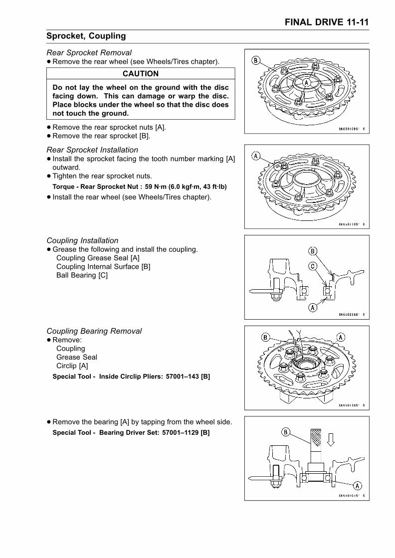
FINAL DRIVE 11-11
Sprocket, Coupling
Rear Sprocket Removal
•Remove the rear wheel (see Wheels/Tires chapter).CAUTION
Do not lay the wheel on the ground with the discfacing down. This can damage or warp the disc.Place blocks under the wheel so that the disc doesnot touch the ground.
•Remove the rear sprocket nuts [A].•Remove the rear sprocket [B].Rear Sprocket Installation
• Install the sprocket facing the tooth number marking [A]outward.
• Tighten the rear sprocket nuts.Torque - Rear Sprocket Nut : 59 N·m (6.0 kgf·m, 43 ft·lb)
• Install the rear wheel (see Wheels/Tires chapter).
Coupling Installation
•Grease the following and install the coupling.Coupling Grease Seal [A]Coupling Internal Surface [B]Ball Bearing [C]
Coupling Bearing Removal
•Remove:CouplingGrease SealCirclip [A]
Special Tool - Inside Circlip Pliers: 57001–143 [B]
•Remove the bearing [A] by tapping from the wheel side.Special Tool - Bearing Driver Set: 57001–1129 [B]
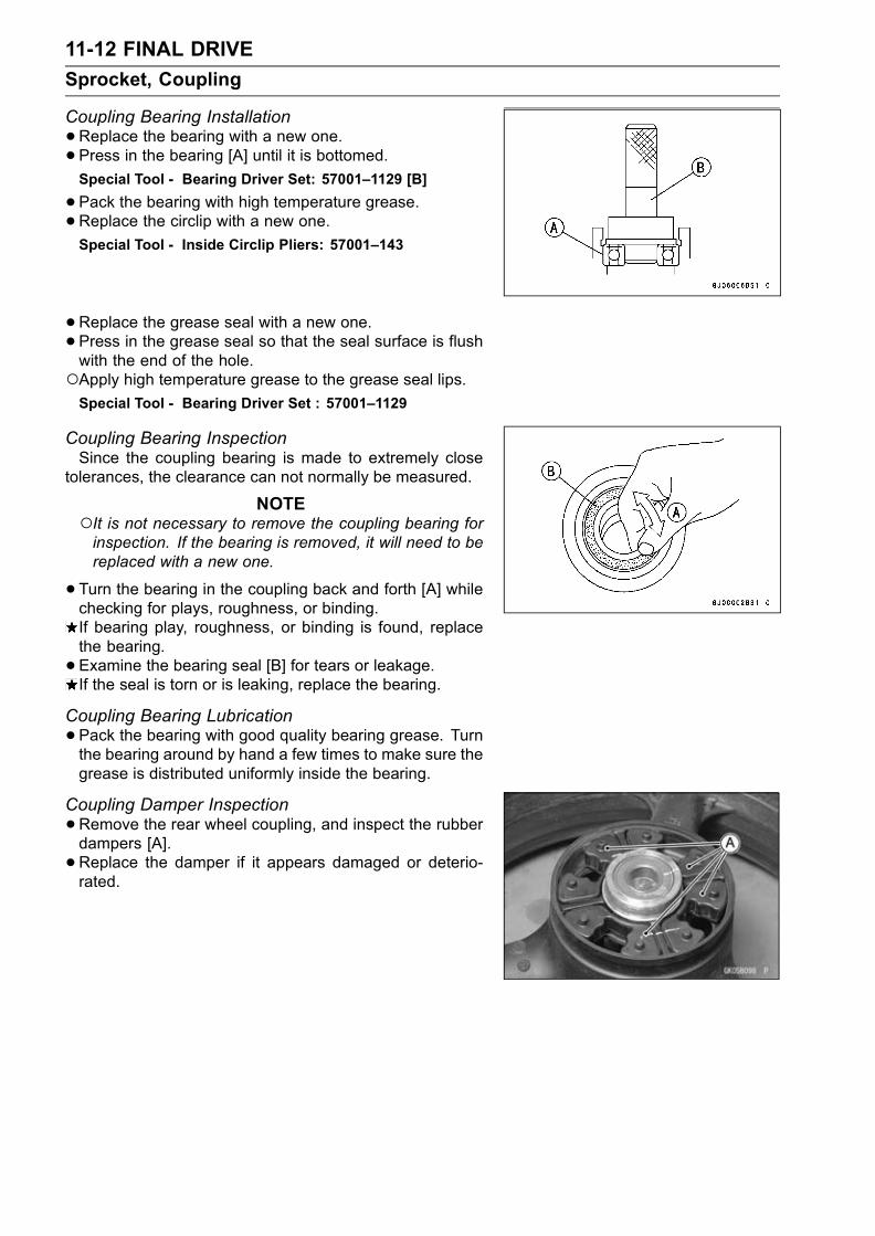
11-12 FINAL DRIVE
Sprocket, Coupling
Coupling Bearing Installation
•Replace the bearing with a new one.• Press in the bearing [A] until it is bottomed.Special Tool - Bearing Driver Set: 57001–1129 [B]
•Pack the bearing with high temperature grease.•Replace the circlip with a new one.Special Tool - Inside Circlip Pliers: 57001–143
•Replace the grease seal with a new one.• Press in the grease seal so that the seal surface is flushwith the end of the hole.Apply high temperature grease to the grease seal lips.Special Tool - Bearing Driver Set : 57001–1129
Coupling Bearing InspectionSince the coupling bearing is made to extremely close
tolerances, the clearance can not normally be measured.
NOTEIt is not necessary to remove the coupling bearing forinspection. If the bearing is removed, it will need to bereplaced with a new one.
•Turn the bearing in the coupling back and forth [A] whilechecking for plays, roughness, or binding.If bearing play, roughness, or binding is found, replacethe bearing.
• Examine the bearing seal [B] for tears or leakage.If the seal is torn or is leaking, replace the bearing.
Coupling Bearing Lubrication
•Pack the bearing with good quality bearing grease. Turnthe bearing around by hand a few times to make sure thegrease is distributed uniformly inside the bearing.
Coupling Damper Inspection
•Remove the rear wheel coupling, and inspect the rubberdampers [A].
•Replace the damper if it appears damaged or deterio-rated.

FINAL DRIVE 11-13
Sprocket, Coupling
Sprocket Wear Inspection
•Visually inspect the engine and rear sprocket teeth forwear and damage.If the teeth are worn as illustrated, replace the sprocket,and inspect the drive chain wear (see Final Drive in thePeriodic Maintenance chapter).[A] Worn Tooth (Engine Sprocket)[B] Worn Tooth (Rear Sprocket)[C] Direction of Rotation
NOTEIf a sprocket requires replacement, the chain is probablyworn also.When replacing a sprocket, inspect the chain.
Rear Sprocket Warp Inspection
•Raise the rear wheel off the ground (see Wheels/Tireschapter) so that it will turn freely.
• Set a dial gauge [A] against the rear sprocket [B] near theteeth as shown, and rotate [C] the rear wheel to measurethe sprocket runout (warp). The difference between thehighest and lowest dial gauge readings is the amount ofrunout (warp).If the runout exceeds the service limit, replace the rearsprocket.
Rear Sprocket WarpStandard: 0.4 mm (0.016 in.) or less
Service Limit: 0.5 mm (0.02 in.)


BRAKES 12-1
12
Brakes
Table of Contents
Exploded View .................................. 12-2Specifications ................................... 12-6Special Tools ..................................... 12-7Brake Pedal ....................................... 12-8
Brake Lever Position Adjustment. 12-8Brake Pedal Position Inspection . 12-8Brake Pedal Position Adjustment 12-8
Calipers ............................................. 12-9Front Caliper Removal ................. 12-9Rear Caliper Removal.................. 12-9Caliper Installation ....................... 12-9Front Caliper Disassembly........... 12-10Front Caliper Assembly................ 12-11Rear Caliper Disassembly ........... 12-11Rear Caliper Assembly ................ 12-12Caliper Fluid Seal Damage.......... 12-13Caliper Dust Seal/Friction BootDamage..................................... 12-13
Caliper Piston and CylinderDamage..................................... 12-13
Caliper Holder Shaft Wear ........... 12-14Brake Pads........................................ 12-15
Front Brake Pad Removal............ 12-15Front Brake Pad Installation......... 12-15Rear Brake Pad Removal ........... 12-15
Rear Brake Pad Installation ......... 12-16Brake Pad Wear Inspection ......... 12-16
Master Cylinder ................................. 12-17Front Master Cylinder Removal ... 12-17Front Master Cylinder Installation 12-17Rear Master Cylinder Removal.... 12-17Rear Master Cylinder Installation. 12-18Front Master CylinderDisassembly.............................. 12-18
Rear Master CylinderDisassembly.............................. 12-18
Master Cylinder Assembly ........... 12-19Master Cylinder Inspection .......... 12-19
Brake Disc ......................................... 12-21Brake Disc Removal .................... 12-21Brake Disc Installation ................. 12-21Brake Disc Wear .......................... 12-21Brake Disc Warp .......................... 12-21
Brake Fluid ........................................ 12-22Level Inspection ........................... 12-22Brake Fluid Change ..................... 12-22Bleeding the Brake Line............... 12-22
Brake Hose........................................ 12-23Brake Hose Removal/Installation. 12-23Brake Hose Inspection................. 12-23

12-2 BRAKES
Exploded View

BRAKES 12-3
Exploded View
TorqueNo. Fastener N·m kgf·m ft·lb Remarks
1 Brake lever pivot bolt 1.0 0.10 89 in·lb Si2 Front master cylinder clamp bolts 8.8 0.90 78 in·lb S3 Front brake light switch screw 1.2 0.12 10 in·lb4 Front brake reservoir cap stopper screw 1.2 0.12 10 in·lb5 Brake lever pivot bolt locknut 6.0 0.61 53 in·lb6 Brake hose banjo bolts 25 2.5 187 Front caliper mounting bolts 34 3.5 258 Front caliper assembly bolts 22 2.2 169 Front brake pad pins 15 1.5 1110 Front brake disc mounting bolts 27 2.8 20 L11 Bleed valves 7.8 0.80 69 in·lb
B: Apply brake fluid.R: Replacement PartsS: Follow the specific tightening sequence.Si: Apply silicone grease (ex. PBC grease).L: Apply a non-permanent locking agent.

12-4 BRAKES
Exploded View

BRAKES 12-5
Exploded View
TorqueNo. Fastener N·m kgf·m ft·lb Remarks
1 Brake hose banjo bolts 25 2.5 182 Rear master cylinder mounting bolts 25 2.5 183 Rear master cylinder push rod locknut 18 1.8 134 Bleed valve 7.8 0.80 69 in·lb5 Rear brake disc mounting bolts 27 2.8 20 L6 Rear caliper mounting bolts 25 2.5 18
B: Apply brake fluid.G: Apply grease.R: Replacement PartsSi: Apply silicone grease (ex. PBC grease).L: Apply a non-permanent locking agent.

12-6 BRAKES
Specifications
Item Standard Service Limit
Brake Lever, Brake Pedal:
Brake lever position 5-way adjustable (to suit rider) - - -
Brake lever free play Non-adjustable - - -
Pedal free play Non-adjustable - - -
Pedal position About 45 mm (1.8 in.) below footpeg top - - -
Brake Discs:
Thickness
Front 5.8 ∼ 6.2 mm (0.23 ∼ 0.24 in.) 5.5 mm (0.22 in.)
Rear 4.8 ∼ 5.2 mm (0.19 ∼ 0.20 in.) 4.5 mm (0.18 in.)
Runout 0.15 mm (0.006 in.) or less 0.3 mm (0.01 in.)

BRAKES 12-7
Special Tools
Inside Circlip Pliers:57001–143
Jack:57001–1238

12-8 BRAKES
Brake Pedal
Brake Lever Position AdjustmentThe brake lever adjuster has 5 positions so that the brake
lever position can be adjusted to suit the operator’s hand.
• Push the lever forward and turn the adjuster [A] to alignthe number with the arrow mark [B] on the lever holder.The distance from the grip to the lever is minimum at num-ber 5 and maximum at number 1.
Brake Pedal Position Inspection
•Check that the brake pedal [A] is in the correct position.[B] Footpeg
Pedal PositionStandard: About 45 mm (1.8 in.) [C] below top of
footpeg
If it is incorrect, adjust the brake pedal position.
Brake Pedal Position Adjustment
NOTEUsually it is not necessary to adjust the pedal position,but always adjust it when push rod locknut has beenloosened.
•Remove the rear master cylinder cover [B], and thentighten the master cylinder bolts [A] only.
• Loosen the locknut [A] and turn the push rod with the hexhead [B] to achieve the correct pedal position.If the length [C] shown is 67 ± 1 mm (2.6 ± 0.04 in.), thepedal position will be within the standard range.
• Tighten:Torque - Rear Master Cylinder Push Rod Locknut: 18 N·m
(1.8 kgf·m, 13 ft·lb)
•Check the brake light switch operation (see Brakes in thePeriodic Maintenance chapter).

BRAKES 12-9
Calipers
Front Caliper Removal
•Loosen the banjo bolt [A] at the brake hose lower end,and tighten it loosely.
•Unscrew the caliper mounting bolts [B], and detach thecaliper [C] from the disc.
CAUTION
Do not loosen the caliper assembly bolts [D]. Takeout only the caliper mounting bolts for caliper re-moval. Loosening the caliper assembly bolts willcause brake fluid leakage.
•Unscrew the banjo bolt and remove the brake hose [E]from the caliper (see Brake Hose Removal/Installation).
CAUTION
Immediately wash away any brake fluid that spills.
NOTEIf the caliper is to be disassembled after removal and ifcompressed air is not available, disassemble the caliperbefore the brake hose is removed (see Front CaliperDisassembly).
Rear Caliper Removal
•Loosen the banjo bolt [A] at the brake hose lower end,and tighten it loosely.
•Unscrew the caliper mounting bolts [B], and detach thecaliper [C] from the disc.
•Unscrew the banjo bolt and remove the brake hose [D]from the caliper (see Brake Hose Removal/Installation).
CAUTION
Immediately wash away any brake fluid that spills.
NOTEIf the caliper is to be disassembled after removal and ifcompressed air is not available, disassemble the caliperbefore the brake hose is removed (see Rear CaliperDisassembly).
Caliper Installation
• Install the caliper and brake hose lower end.Replace the washers on each side of hose fitting with newones.
• Tighten:Torque - Caliper Mounting Bolts (Front): 34 N·m (3.5 kgf·m,
25 ft·lb)Caliper Mounting Bolts (Rear): 25 N·m (2.5 kgf·m,18 ft·lb)
Brake Hose Banjo Bolt: 25 N·m (2.5 kgf·m, 18 ft·lb)
•Check the fluid level in the brake reservoirs.• Bleed the brake line (see Brakes in the Periodic Mainte-nance chapter).
• Check the brake for good braking power, no brake drag,and no fluid leakage.

12-10 BRAKES
Calipers
WARNINGDo not attempt to drive the motorcycle until a fullbrake lever or pedal is obtained by pumping thebrake lever or pedal until the pads are against thedisc. The brakes will not function on the first appli-cation of the lever or pedal if this is not done.
Front Caliper Disassembly
•Loosen the front caliper assembly bolt [A] and banjo bolt[B], and tighten them loosely.
•Remove:Front Caliper [C] (see Front Caliper Removal)Brake Pads (see Front Brake Pad Removal)Front Caliper Assembly BoltsO-rings
•Using compressed air, remove the pistons. One way toremove the pistons is as follows.Install a rubber gasket [A] and a wooden board [B] morethan 10 mm (0.4 in.) thick on the caliper half, and fas-ten them together with a suitable bolt and nut as shown.Leave one of the oil passages [C] open.Lightly apply compressed air [D] to the oil passage untilthe pistons hit the rubber gasket. Block the hose jointopening [E] during this operation if the caliper half hasthe opening.Bolt and Nut [F]Oil Passage sealed by Rubber Gasket. [G]Push down. [H]
WARNINGTo avoid serious injury, never place your fingers orpalm in front of the piston. If you apply compressedair into the caliper, the piston may crush your handor fingers.
Pull out the pistons by hand.•Remove the dust seals [A] and fluid seals [B].• Remove the bleed valve [C] and rubber cap [D].•Repeat the previous step to remove the pistons from theother side of the caliper body.
NOTEIf compressed air is not available, do as follows for bothcalipers coincidentally, with the brake hose connectedto the caliper.Prepare a container for brake fluid, and perform thework above it.Remove the spring and pads (see Front Brake Pad Re-moval).Pump the brake lever until the pistons come out of thecylinders, and then disassemble the caliper.

BRAKES 12-11
Calipers
Front Caliper Assembly
•Clean the caliper parts except for the pads.CAUTION
For cleaning of the parts, use only disc brake fluid,isopropyl alcohol, or ethyl alcohol.
• Install the bleed valve and rubber cap.Torque - Bleed Valve: 7.8 N·m (0.80 kgf·m, 69 in·lb)
•Replace the fluid seals [A] with new ones.Apply brake fluid to the fluid seals, and install them intothe cylinders by hand.
•Replace the dust seals [B] with new ones if they are dam-aged.Apply brake fluid to the dust seals, and install them intothe cylinders by hand.
•Replace the O–rings [A] if they are damaged.• Apply brake fluid to the outside of the pistons, and pushthem into each cylinder by hand.
• Be sure to install the O-rings.• Tighten the caliper assembly bolts.Torque - Front Caliper Assembly Bolts: 22 N·m (2.2 kgf·m,
16 ft·lb)
• Install the pads (see Front Brake Pad Installation).•Wipe up any spilled brake fluid on the caliper with wetcloth.
Rear Caliper Disassembly
•Remove the rear caliper.•Remove the pads and anti-rattle spring (see Rear BrakePad Removal).
• Using compressed air, remove the piston.Cover the caliper opening with a clean, heavy cloth [A].Remove the piston by lightly applying compressed air [B]to where the brake line fits into the caliper.
WARNINGTo avoid serious injury, never place your fingers orpalm inside the caliper opening. If you apply com-pressed air into the caliper, the piston may crushyour hand or fingers.
•Remove the dust seal and fluid seal.• Remove the bleed valve and rubber cap.
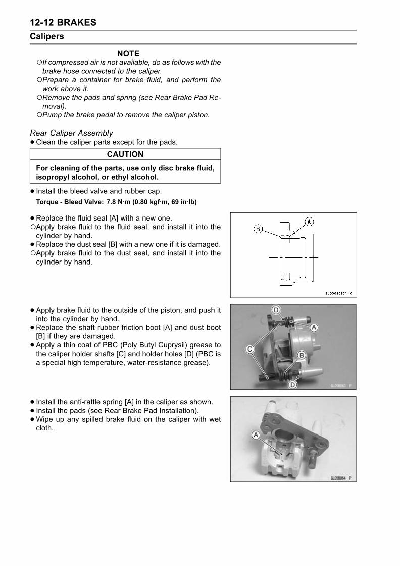
12-12 BRAKES
Calipers
NOTEIf compressed air is not available, do as follows with thebrake hose connected to the caliper.Prepare a container for brake fluid, and perform thework above it.Remove the pads and spring (see Rear Brake Pad Re-moval).Pump the brake pedal to remove the caliper piston.
Rear Caliper Assembly
•Clean the caliper parts except for the pads.CAUTION
For cleaning of the parts, use only disc brake fluid,isopropyl alcohol, or ethyl alcohol.
• Install the bleed valve and rubber cap.Torque - Bleed Valve: 7.8 N·m (0.80 kgf·m, 69 in·lb)
•Replace the fluid seal [A] with a new one.Apply brake fluid to the fluid seal, and install it into thecylinder by hand.
•Replace the dust seal [B] with a new one if it is damaged.Apply brake fluid to the dust seal, and install it into thecylinder by hand.
• Apply brake fluid to the outside of the piston, and push itinto the cylinder by hand.
•Replace the shaft rubber friction boot [A] and dust boot[B] if they are damaged.
• Apply a thin coat of PBC (Poly Butyl Cuprysil) grease tothe caliper holder shafts [C] and holder holes [D] (PBC isa special high temperature, water-resistance grease).
• Install the anti-rattle spring [A] in the caliper as shown.• Install the pads (see Rear Brake Pad Installation).•Wipe up any spilled brake fluid on the caliper with wetcloth.

BRAKES 12-13
Calipers
Caliper Fluid Seal DamageThe fluid seals [A] around the piston maintain the proper
pad/disc clearance. If the seals are not satisfactory, padwear will increase, and constant pad drag on the disc willraise brake and brake fluid temperature.
•Remove the calipers (see Brakes chapter)•Replace the fluid seals under any of the following condi-tions: (a) fluid leakage around the pad; (b) brakes over-heat (c) there is a large difference in inner and outer padwear; (d) the seal is stuck to the piston.If the fluid seal is replace, replace the dust seal as well.Also, replace all seals every other time the pads arechanged.
Caliper Dust Seal/Friction Boot Damage
•Remove the calipers (see Brakes chapter).• Check that the dust seals [B] and friction boot [C] are notcracked, worn, swollen, or otherwise damaged.If they show any damage, remove the caliper bracket andreplace them.Front Caliper [D]Rear Caliper [E]Dust Boot [F]
Caliper Piston and Cylinder Damage
•Visually inspect the piston [A] and cylinder surfaces.Replace the caliper if the cylinder and piston are badlyscores or rusty.Front Caliper [B]Rear Caliper [C]Dust Boot [D]

12-14 BRAKES
Calipers
Caliper Holder Shaft WearThe caliper bodymust slide smoothly on the caliper holder
shafts [A]. If the body does not slide smoothly, one pad willwear more than the other, pad wear will increase, and con-stant drag on the disc will raise brake and brake fluid tem-perature.
•Check to see that the caliper holder shafts are not badlyworn or stepped, and that the rubber friction boots are notdamaged.If the rubber friction boot is damaged, replace the rubberfriction boot. To replace the friction boot, remove the padsand the caliper bracket.If the caliper holder shaft is damage, replace the caliperbracket.

BRAKES 12-15
Brake Pads
Front Brake Pad Removal
•Remove:Pad Spring Bolts [A]Pad Spring [B]
•Remove:Brake Pads [A]
Front Brake Pad Installation
•Push the caliper pistons in by hand as far as they will go.• Install the brake pads.• Install the pad pin and clip. The clip must be "outside" ofthe pads.
• Install the pad spring and tighten the pad spring bolts.Torque - Front Brake Pad Spring Bolts: 2.9 N·m (0.30 kgf·m,
26 in·lb)
WARNINGDo not attempt to drive the motorcycle until a fullbrake lever is obtained by pumping the brake leverand the pads are against the disc. The brake willnot function on the first application of the lever ifthis is not done.
Rear Brake Pad Removal
•Remove the caliper with the hose installed.•Remove:Clip [A]Pad Pin [B]Brake Pads [C]

12-16 BRAKES
Brake Pads
Rear Brake Pad Installation
•Push the caliper piston in by hand as far as it will go.• Install the anti-rattle spring in place.• Install the brake pads.• Install the pad pin and clip. The clip must be "outside" ofthe pads.
• Install the caliper (see Caliper Installation).WARNING
Do not attempt to drive the motorcycle until a fullbrake pedal is obtained by pumping the brake pedaluntil the pads are against the disc. The brake willnot function on the first application of the pedal ifthis is not done.
Brake Pad Wear InspectionRefer to the Brakes in the Periodic Maintenance chapter.

BRAKES 12-17
Master Cylinder
Front Master Cylinder Removal
•Loosen the reservoir bracket bolts [A].
• Disconnect the front brake light switch connectors.•Remove the banjo bolt [A] to disconnect the brake hosefrom the master cylinder (see Brake Hose Removal/In-stallation).
•Unscrew the clamp bolts [B], and take off the master cylin-der [C] as an assembly with the reservoir, brake lever, andbrake switch installed.
CAUTION
Immediately wash away any brake fluid that spills.
Front Master Cylinder Installation
•Set the front master cylinder to match its mating surface[A] to the punch mark [B] of the handlebar.
• The master cylinder clamp must be installed with the ar-row mark [C] upward.
• Tighten the upper clamp bolt first, and then the lowerclamp bolt. There will be a gap at the lower part of theclamp after tightening.
Torque - Front Master Cylinder Clamp Bolts: 8.8 N·m (0.90kgf·m, 78 in·lb)
•Replace the washers that are on each side of the hosefitting with new ones.
• Tighten:Torque - Brake Hose Banjo Bolt: 25 N·m (2.5 kgf·m, 18 ft·lb)
•Bleed the brake line (see Brakes in the Periodic Mainte-nance chapter).
• Check the brake for good braking power, no brake drag,and no fluid leakage.
Rear Master Cylinder Removal
•Unscrew the brake hose banjo bolt [A] on themaster cylin-der (see Brake Hose Removal/Installation).
• Pull off the reservoir hose lower end [B], and drain thebrake fluid into a container.
•Remove the cotter pin [C] and join pin [D].NOTE
Pull off the joint pin while pressing down the brakepedal.
•Unscrew the master cylinder mounting bolts [E], and takeoff the master cylinder [F] and master cylinder cover [G].

12-18 BRAKES
Master Cylinder
Rear Master Cylinder Installation
•Replace the cotter pin with a new one.•Replace the washers that are on each side of hose fittingwith new ones.
• Tighten:Torque - Rear Master Cylinder Mounting Bolts: 25 N·m (2.5
kgf·m, 18 ft·lb)Brake Hose Banjo Bolt: 25 N·m (2.5 kgf·m, 18 ft·lb)
•Bleed the brake line (see Brakes in the Periodic Mainte-nance chapter).
• Check the brake for good braking power, no brake drag,and no fluid leakage.
Front Master Cylinder Disassembly
•Remove the front master cylinder (see Front Master Cylin-der Removal).
• Remove the reservoir cap and diaphragm, and pour thebrake fluid into a container.
•Unscrew the locknut and pivot bolt, and remove the brakelever.
• Pull the dust cover [A] out of place, and remove the circlip[B].
Special Tool - Inside Circlip Pliers: 57001–143
•Take out the piston [C], secondary cup [D], primary cup[E], and return spring [F].
CAUTION
Do not remove the secondary cup from the pistonsince removal will damage it.
Rear Master Cylinder Disassembly
NOTEDo not remove the push rod clevis for master cylinderdisassembly since removal requires brake pedal posi-tion adjustment.
•Remove the rear master cylinder (see Rear Master Cylin-der Removal).
• Slide the dust cover on the push rod out of place, andremove the circlip.
Special Tool - Inside Circlip Pliers: 57001–143
•Pull out the push rod with the piston stop.• Take off the piston [A], secondary cup [B], primary cup [C],and return spring [D].
CAUTION
Do not remove the secondary cup from the pistonsince removal will damage it.

BRAKES 12-19
Master Cylinder
Master Cylinder Assembly
•Before assembly, clean all parts including the mastercylinder with brake fluid or alcohol.
CAUTION
Except for the disc pads and disc, use only discbrake fluid, isopropyl alcohol, or ethyl alcohol forcleaning of the brake parts. Do not use any otherfluid for cleaning of these parts, Gasoline, engineoil, or any other petroleum distillate will cause de-terioration of the rubber parts. Oil spilled on anypart will be difficult to wash off completely, and willeventually deteriorate the rubber used in the discbrake.
•Apply brake fluid to the removed parts and to the innerwall of the cylinder.
• Take care not to scratch the piston or the inner wall of thecylinder.
• Apply silicone grease (ex. PBC grease)Brake Lever Pivot BoltBrake Lever Pivot ContactPush Rod Contact (Rear)Dust Covers
• Tighten:Torque - Brake Lever Pivot Bolt: 1.0 N·m (0.10 kgf·m, 9
in·lb)Brake Lever Pivot Bolt Locknut: 5.9 N·m (0.60kgf·m, 52 in·lb)
Master Cylinder Inspection
•Remove the master cylinders (see Brakes chapter).• Disassemble the front and rear master cylinders.•Check that there are no scratches, rust or pitting on theinner wall [A] of each master cylinder and on the outsideof each piston [B].If a master cylinder or piston shows any damage, replacethem.
• Inspect the primary cup [C] and secondary cup [D].If a cup is worn, damaged softened (rotted), or swollen,the piston assembly should be replaced to renew thecups.If fluid leakage is noted at the brake lever, the piston as-sembly should be replaced to renew the cups.Front Master Cylinder [J]

12-20 BRAKES
Master Cylinder
•Check the dust covers [E] for damage.If they are damaged, replace them.
•Check the piston return spring [F] for any damage.If the springs are damaged, replace them.
•Check that relief port [G] and supply port [H] are notplugged.If the relief port becomes plugged, the brake pads willdrag on the disc. Blow the ports clean with compressedair.Rear Maser Cylinder [K]

BRAKES 12-21
Brake Disc
Brake Disc Removal
•Remove the wheel (see Wheels/Tires chapter).• Unscrew the mounting bolts, and take off the disc.•Remove the gasket (Front Brake Disc only).Brake Disc Installation
•Replace the gasket with a new one (Front Brake Disconly).
• Install the brake disc on the wheel so that the marked side[B] faces out.
• Apply a non-permanent locking agent to the threads ofthe rear brake disc mounting bolts [A].
• Tighten:Torque - Brake Disc Mounting Bolts: 27 N·m (2.8 kgf·m, 20
ft·lb)
Brake Disc Wear
•Measure the thickness of each disc [A] at the point whereit has worn the most.If the disc has worn past the service limit, replace it.[B] Measuring Area
Front Brake Discs ThicknessStandard: 5.8 ∼ 6.2 mm (0.23 ∼ 0.24 in.)Service Limit: 5.5 mm (0.22 in.)
Rear Brake Discs ThicknessStandard: 4.8 ∼ 5.1 mm (0.19 ∼ 0.20 in.)Service Limit: 4.5 mm (0.18 in.)
Brake Disc Warp
• Jack up the motorcycle so that the wheel is off the ground(see Wheels/Tires chapter).
Special Tool - Jack: 57001–1238
For front disc inspection, turn the handlebar fully to oneside.
• Set up a dial gauge against the disc [A] as shown andmeasure disc runout, while turning [B] the wheel by hand.If runout exceeds the service limit, replace the disc.
Disc RunoutStandard: 0.15 mm (0.006 in.) or less
Service Limit: 0.3 mm (0.01 in.)

12-22 BRAKES
Brake Fluid
Level InspectionRefer to the Brakes in the Periodic Maintenance chapter.Brake Fluid ChangeRefer to the Brakes in the Periodic Maintenance chapter.Bleeding the Brake LineRefer to the Brakes in the Periodic Maintenance chapter.
BRAKES 12-23
Brake Hose
Brake Hose Removal/Installation
CAUTION
Brake fluid quickly ruins painted or plastic sur-faces; any spilled fluid should be completely wipedup immediately with wet cloth.
•When removing the brake hose, take care not to spill thebrake fluid on the painted or plastic parts.
•When removing the brake hose, temporarily secure theend of the brake hose to some high place to keep fluidloss to a minimum.
• There are washers on each side of the brake hose fitting.Replace them with new ones when installing.
•When installing the hoses, avoid sharp bending, kinking,flattening or twisting, and route the hoses according toCable, Wire, and Hose Routing section in Appendix chap-ter.
• Tighten:Torque - Brake Hose Banjo Bolts: 25 N·m (2.5 kgf·m, 18
ft·lb)
•Bleed the brake line after installing the brake hose (seeBrakes in the Periodic Maintenance chapter).
Brake Hose InspectionRefer to the Brakes in the Periodic Maintenance chapter.

SUSPENSION 13-1
13
Suspension
Table of Contents
Exploded View........................................................................................................................ 13-2Specifications ......................................................................................................................... 13-6Special Tools .......................................................................................................................... 13-7Front Fork ............................................................................................................................... 13-9
Rebound Damping Force Adjustment............................................................................... 13-9Compression Damping Force Adjustment ........................................................................ 13-9Spring Preload Adjustment ............................................................................................... 13-10Front Fork Removal (each fork leg) .................................................................................. 13-10Front Fork Installation ....................................................................................................... 13-11Front Fork Oil Change ...................................................................................................... 13-11Front Fork Disassembly .................................................................................................... 13-15Front Fork Assembly......................................................................................................... 13-15Inner Tube Inspection ....................................................................................................... 13-16Dust Seal Inspection ......................................................................................................... 13-17Spring Tension .................................................................................................................. 13-17
Rear Shock Absorber ............................................................................................................. 13-18Rebound Damping Force Adjustment............................................................................... 13-18Compression Damping Force Adjustment ........................................................................ 13-18Spring Preload Adjustment ............................................................................................... 13-18Rear Shock Absorber Removal ........................................................................................ 13-19Rear Shock Absorber Installation ..................................................................................... 13-20Rear Shock Absorber Inspection ...................................................................................... 13-20Rear Shock Absorber Scrapping ...................................................................................... 13-20
Swingarm................................................................................................................................ 13-21Swingarm Removal........................................................................................................... 13-21Swingarm Installation........................................................................................................ 13-21Swingarm Bearing Removal ............................................................................................. 13-22Swingarm Bearing Installation .......................................................................................... 13-23Swingarm Bearing, Sleeve Inspection .............................................................................. 13-23Swingarm Pivot Lubrication .............................................................................................. 13-23Chain Guide Inspection..................................................................................................... 13-23
Tie-Rod, Rocker Arm.............................................................................................................. 13-24Tie-Rod Removal .............................................................................................................. 13-24Tie-Rod Installation ........................................................................................................... 13-24Rocker Arm Removal........................................................................................................ 13-24Rocker Arm Installation..................................................................................................... 13-24Rocker Arm/Tie-Rod Bearing, Sleeve Inspection ............................................................. 13-25Rocker Arm/Tie-Rod Lubrication....................................................................................... 13-25

13-2 SUSPENSION
Exploded View

SUSPENSION 13-3
Exploded View
TorqueNo. Fastener N·m kgf·m ft·lb Remarks
1 Front fork top plug 23 2.3 172 Front fork clamp bolts (upper) 20 2.0 14.53 Front fork clamp bolts (lower) 20 2.0 14.5 AL4 Front fork bottom allen bolts 40 4.0 30 L5 Front axle clamp bolts 20 2.0 14.5 AL6 Piston rod nut 15 1.5 11
AL: Tighten the two clamp bolts alternately two times to ensure even tightening torque.L: Apply a non-permanent locking agent.R: Replacement Parts

13-4 SUSPENSION
Exploded View

SUSPENSION 13-5
Exploded View
TorqueNo. Fastener N·m kgf·m ft·lb Remarks
1 Rear shock absorber bracket nut 59 6.0 432 Rear shock absorber Nuts (upper and lower) 34 3.5 253 Tie-Rod Nuts 59 6.0 434 Uni-Trak rocker arm nut 34 3.5 255 Swingarm pivot shaft nut 108 11 816 Swingarm pivot shaft ZX636 20 2.0 14
ZX600 25 2.5 187 Swingarm pivot shaft locknut 98 10 72
No. Parts Parts No. Remarks8 Spacer set (Option) 92026–1586 T1.0/T2.0/T3.2/T4.59 Swingarm bracket (ZX600 Only)
STD (LH) 92152–1482(RH) 92152–1483
Swingarm pivot height nochanges.
OPTION (LH) 92152–0042(RH) 92152–0043
Swingarm pivot height changesplus or minus 1 mm (0.039 in.).
(LH) 92152–0044(RH) 92152–0045
Swingarm pivot height changesplus or minus 2 mm (0.079 in.).
G: Apply or add grease.R: Replacement Parts

13-6 SUSPENSION
Specifications
Item Standard
Front Fork (per one unit):
Fork inner tube diameter 41 mm (1.6 in.)
Air Pressure Atmospheric pressure (Non-adjustable)
Rebound damper setting 8th click from the first click of the fully clockwise position
(Usable Range: 0 ←→ 11 clicks)
Compression damper setting 8th click from the first click of the fully clockwise position
(Usable Range: 0 ←→ 13 clicks)
Fork spring preload setting Adjuster protrusion is 14 mm (0.55 in.)
(Usable Range: 4 ∼ 19 mm) (0.16 ∼ 0.75 in.)Fork Oil:
Viscosity KAYABA 01 or SAE 5W
Amount:
When changing oil Aprox. 410 mL (13.9 US oz.)
After disassembly and 482 ± 4 mL (16.3 ± 0.14 US oz.)
completely dry
Fork oil level: (fully compressed, 101 ± 2 mm (3.98 ± 0.08 in.)
without spring, below from the top
of the inner tube)
Fork spring free length 248 mm (9.76 in.) (Service limit: 243 mm (9.57 in.))
Rear Shock Absorber:
Rebound damper set 4 1/4 turns out from the fully clockwise position
ZX636–B2 ∼ : 2 turns out from the fully clockwise position
(Usable Range: 0 ←→ 4 1/2 turns out)
Compression damper set 3 1/2 turns out from the fully clockwise position
ZX636–B2 ∼ : 2 1/2 turns out from the fully clockwise position
(Usable Range: 0 ←→ 4 turns out)
Spring preload setting position
Standard Spring length: 180 mm (7.1 in.)
Usable range Spring length: 171.5 ∼ 191.5 mm (6.8 ∼ 7.5 in.)(weaker to stronger)
Gas pressure 980 kPa (10 kgf/cm², 142 psi, Non-adjustable)
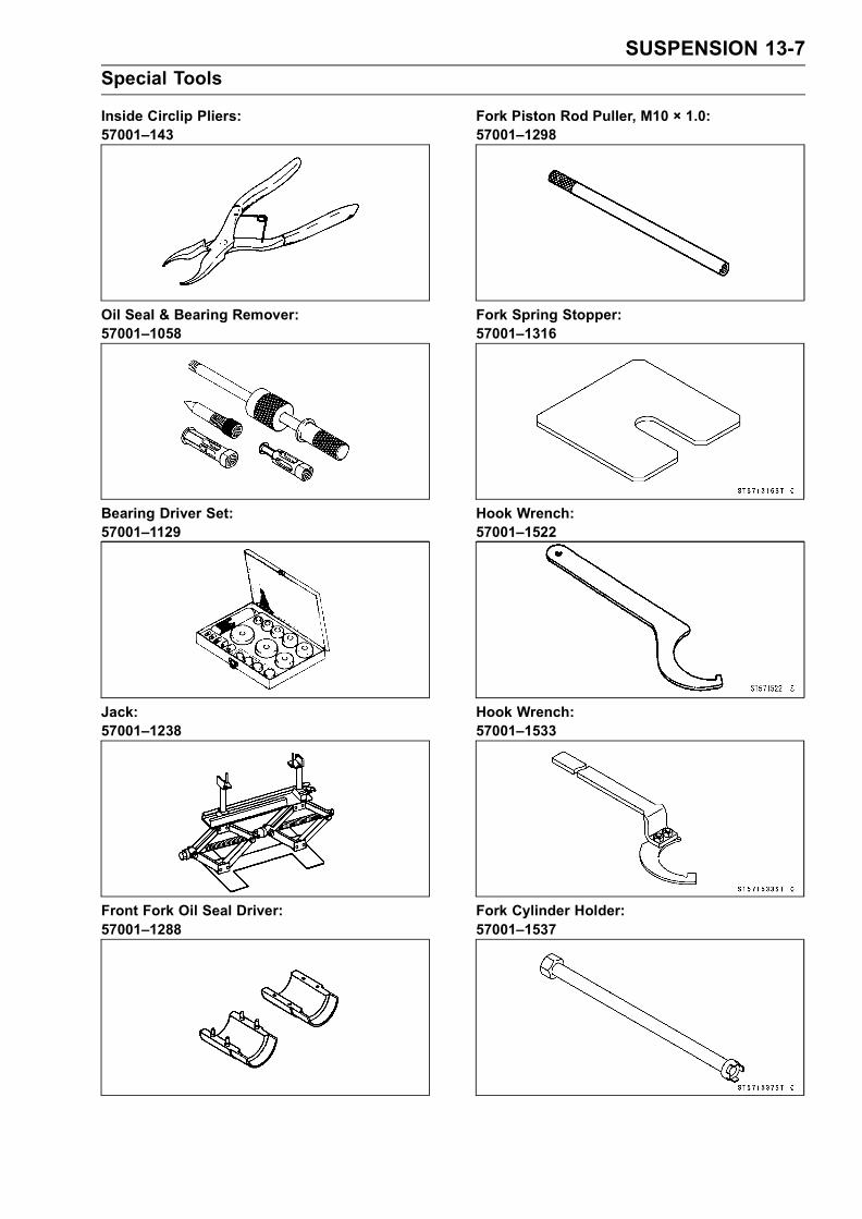
SUSPENSION 13-7
Special Tools
Inside Circlip Pliers:57001–143
Oil Seal & Bearing Remover:57001–1058
Bearing Driver Set:57001–1129
Jack:57001–1238
Front Fork Oil Seal Driver:57001–1288
Fork Piston Rod Puller, M10 × 1.0:57001–1298
Fork Spring Stopper:57001–1316
Hook Wrench:57001–1522
Hook Wrench:57001–1533
Fork Cylinder Holder:57001–1537

13-8 SUSPENSION
Special Tools
Fork Spring Compressor:57001–1540
Swingarm Pivot Nut Wrench:57001–1541

SUSPENSION 13-9
Front Fork
Rebound Damping Force Adjustment
•To adjust the rebound damping force, turn the rebounddamping adjuster [A] until you feel a click.The standard adjuster setting for the average-build riderof 68 kg (150 lb) with no passenger and no accessoriesis the 8th click from the 1st click of the fully clockwiseposition.
WARNINGIf both adjusters are not adjusted equally, handlingmay be impaired and a hazardous condition mayresult.
The damping force can be left soft for average riding. Butit should be adjusted harder for high speed riding or ridingwith a passenger. If the damping feels too soft or too stiff,adjust it in accordance with the following table.
Rebound Damping Force Adjustment
Adjuster Damping
Position Force Setting Load Road Speed
11 Weak Soft Light Good Low
↑ ↑ ↑ ↑ ↑ ↑↓ ↓ ↓ ↓ ↓ ↓0 Strong Hard Heavy Bad High
Compression Damping Force Adjustment
•To adjust the compression damping force, turn the com-pression damping adjuster [A] until you feel a click.The standard adjuster setting for the average-build riderof 68 kg (150 lb) with no passenger and no accessoriesis the 8th click from the 1st click of the fully clockwiseposition.
WARNINGIf both adjusters are not adjusted equally, handlingmay be impaired and a hazardous condition mayresult.
The damping force can be left soft for average riding. Butit should be adjusted harder for high speed riding or ridingwith a passenger. If the damping feels too soft or too stiff,adjust it in accordance with the following table.
Compression Damping Force Adjustment
Adjuster Damping
Position Force Setting Load Road Speed
13 Weak Soft Light Good Low
↑ ↑ ↑ ↑ ↑ ↑↓ ↓ ↓ ↓ ↓ ↓0 Strong Hard Heavy Bad High
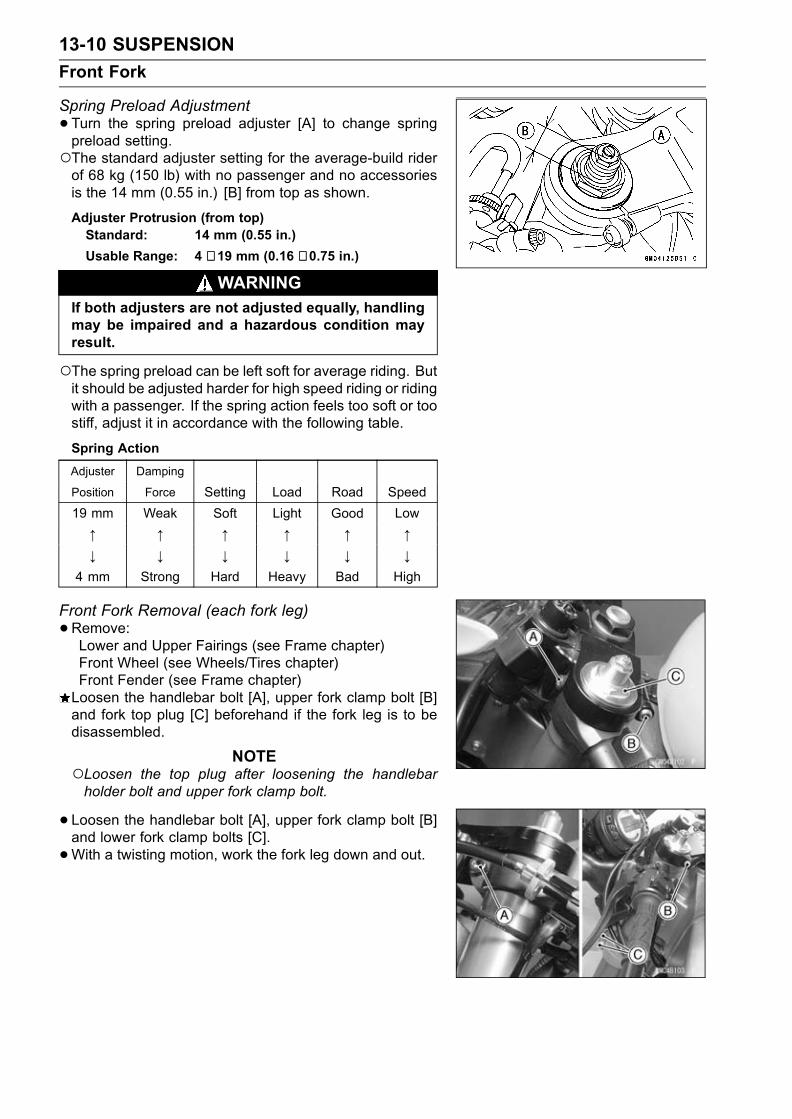
13-10 SUSPENSION
Front Fork
Spring Preload Adjustment
•Turn the spring preload adjuster [A] to change springpreload setting.The standard adjuster setting for the average-build riderof 68 kg (150 lb) with no passenger and no accessoriesis the 14 mm (0.55 in.) [B] from top as shown.
Adjuster Protrusion (from top)Standard: 14 mm (0.55 in.)
Usable Range: 4 ∼ 19 mm (0.16 ∼ 0.75 in.)
WARNINGIf both adjusters are not adjusted equally, handlingmay be impaired and a hazardous condition mayresult.
The spring preload can be left soft for average riding. Butit should be adjusted harder for high speed riding or ridingwith a passenger. If the spring action feels too soft or toostiff, adjust it in accordance with the following table.
Spring Action
Adjuster Damping
Position Force Setting Load Road Speed
19 mm Weak Soft Light Good Low
↑ ↑ ↑ ↑ ↑ ↑↓ ↓ ↓ ↓ ↓ ↓
4 mm Strong Hard Heavy Bad High
Front Fork Removal (each fork leg)
•Remove:Lower and Upper Fairings (see Frame chapter)Front Wheel (see Wheels/Tires chapter)Front Fender (see Frame chapter)Loosen the handlebar bolt [A], upper fork clamp bolt [B]and fork top plug [C] beforehand if the fork leg is to bedisassembled.
NOTELoosen the top plug after loosening the handlebarholder bolt and upper fork clamp bolt.
•Loosen the handlebar bolt [A], upper fork clamp bolt [B]and lower fork clamp bolts [C].
•With a twisting motion, work the fork leg down and out.

SUSPENSION 13-11
Front Fork
Front Fork Installation
• Install the fork so that the top end [A] of the outer tube isflush with the upper surface [B] of the steering stem headbracket.
• Tighten the lower fork clamp bolts and fork top bolt.Torque - Front Fork Clamp Bolts (Lower): 20 N·m (2.0
kgf·m, 14.5 ft·lb)Front Fork Top Plug: 23 N·m (2.3 kgf·m, 17 ft·lb)
•Tighten the handlebar holder bolt upper fork clamp bolt.Torque - Handlebar Holder Bolt: 25 N·m (2.5 kgf·m, 18 ft·lb)
Front Fork Clamp Bolt (Upper): 20 N·m (2.0 kgf·m,14.5 ft·lb)
NOTETighten the two clamp bolts alternately two times to en-sure even tightening torque.Tighten the top plug before tightening the handlebarholder bolt upper fork clamp bolt.
• Install the removed parts (see appropriate chapters).• Adjust the spring preload and the damping force.Front Fork Oil Change
•Remove the front fork (see Front Fork Removal).• Hold the inner tube lower end in a vise.•Unscrew the top plug [A] out of the outer tube.
• Install the clamps [A] as shown.NOTE
Set the clamps so that the cutout [B] of the upper sidedoes not touch the tongue shape of stopper, pull up theouter tube [C] to hold it by the clamps, and then tightenthe two bolts [D]. The outer tube is used as a guide.
Special Tool - Fork Spring Compressor: 57001–1540
•Screw the handles in the clamps to the bottom.

13-12 SUSPENSION
Front Fork
•While holding up the top plug by one person, push downthe fork spring compressor and insert the fork spring stop-per [A] between the piston rod nut [B] and the clamps [C].
Special Tool - Fork Spring Stopper: 57001–1316
•Holding the piston rod nut with a wrench [A], remove thetop plug [B] from the piston rod.
•Remove:Washer [A]Collar [B]Rebound Damping Adjuster Rod [C]Fork Spring [D]
•Drain the fork oil into a suitable container.Pump the piston rod [B] up and down at least ten times toexpel the oil from the fork.
Special Tool - Fork Piston Rod Puller, M12 × 12.5:57001–1289 [A]
•Hold the fork tube upright, press the inner tube [A] andthe piston rod all the way down.
• Pour in the type and amount of fork oil specified.Fork OilViscosity: KAYABA 01 or SAE 5W
Amount (per side)
When changing oil: approx. 410 mL (13.9 US oz.)
After disassembly andcompletely dry:
482 ± 4 mL (16.3 ± 0.14 USoz.)

SUSPENSION 13-13
Front Fork
If necessary, measure the oil level as follows.Hold the inner tube vertically in a vise.Pump the inner tube several times to expel air bubbles.Using the piston rod puller [A], move the piston rod [B] upand down more than ten times in order to expel all the airfrom the fork oil.
Special Tool - Fork Piston Rod Puller, M12 × 1.25: 57001-1289
Remove the piston rod puller.Wait until the oil level settles.With the fork fully compressed and the piston rod fullypushed in, insert a tape measure or rod into the innertube, and measure the distance from the top of the outertube to the oil.
Oil Level (fully compressed, without spring)Standard: 101 ± 2 mm (3.98 ± 0.08 in)
(from the top of the outer tube)
NOTEFork oil lever may also be measured using the fork oillevel gauge.
Special Tool - Fork Oil Level Gauge: 57001-1290 [A]
With the fork fully compressed and without fork spring,insert the gauge tube into the inner tube [B] and positionthe stopper across the top end [F] of the outer tube [C].Set the gauge stopper [D] so that its lower side shows theoil level distance specified [E].Pull the handle slowly to pump out the excess oil until theoil no longer comes out.If no oil is pumped out, there is insufficient oil in the innertube. Pour in enough oil, then pump out the excess oil asshown above.
• Screw the fork piston rod puller onto the end of the pistonrod.
Special Tool - Fork Piston Rod Puller, M12 × 1.25:57001–1289
•Pull the puller up above the outer tube top.• Install the fork spring [A] with the smaller end facing [B]upward.
• Install:Spring SeatCollar

13-14 SUSPENSION
Front Fork
•Screw the rod nut [B] onto the piston rod [A] as shown.• Insert the rebound damping adjuster rod [C] into the pistonrod.
•Check the distance [C] between the bottom end [A] of thetop plug and rebound damping adjuster [B] with a pair ofvernier caliper.[C]: 13 mm (0.51 in)
• Set the fork spring compressor [A] on the washer usingthe outer tube as a guide.
Special Tool - Fork Spring Compressor: 57001-1540
•While holding up the fork piston rod puller [B] by one per-son, push down the fork spring compressor and insert thefork spring stopper [C] between the piston rod nut [D] andthe clamps of the fork spring compressor.
Special Tool - Fork Spring Stopper: 57001–1316
•Remove the piston rod puller.• Screw in the top plug [A] stopped onto the piston rod.•Check the O-ring [B] on the top plug and replace it with anew one if damaged.
•Holding the top plug with a wrench, tighten the piston rodnut [C] against the top plug.
Torque - Piston Rod Nut: 15 N·m (1.5 kgf·m, 11 ft·lb)
•While holding up the fork spring compressor, pull out thefork spring stopper.
•Remove the fork spring compressor.•Raise the outer tube and screw the top plug into it andinstall it to the steering stem.
•Screw in the spring preload adjuster [A] of the top plugso that the distance between the adjuster top and the topplug surface [B] is 14 mm (0.55 in) [C].
• Turn in the rebound damping adjuster [D] until the fullytightened position and turn backward the 8th click.
• Install the front fork (see Front Fork Installation).

SUSPENSION 13-15
Front Fork
Front Fork Disassembly
•Remove the front fork (see Front Fork Removal).• Drain the fork oil (see Front Fork Oil Change).•Hold the front fork in a vise [A].• Stop the cylinder [B] from turning by using the fork cylinderholder [C].
Special Tool - Fork Cylinder Holder: 57001-1537
•Unscrew the allen bolt [D], then take the bolt and gasketout of the bottom of the inner tube.
• Take the cylinder unit [A].Do not disassemble the cylinder unit.
• Separate the outer tube from the inner tube.
• Pull out the dust seal.• Remove the retaining ring [A] from the outer tube.•Remove the oil seal [B] and washer [C].
Front Fork Assembly
•Replace the following parts with a new one.Oil SealBottom Allen Bolt Gasket
• Insert the cylinder unit [A] into the inner tube [B].• Stop the cylinder from turning by using the fork cylinderholder.
Special Tool - Fork Cylinder Holder: 57001-1537
•Apply a non-permanent locking agent to the allen bolt andtighten it.
Torque - Front Fork Bottom Allen Bolt: 40 N·m (4.0 kgf·m,30 ft·lb)

13-16 SUSPENSION
Front Fork
• Install the following parts into the inner tube [A].Dust Seal [B]Circlip [C]Oil Seal [D]Washer [E]
• Insert the inner tube to the outer tube.• After installing the washer, install the oil seal [A] by usingthe fork oil seal driver [B].
Special Tool - Front Fork Oil Seal Driver: 57001-1288
• Install the circlip and dust seal.• Pour in the specified type of oil (see Front Fork OilChange).
Inner Tube Inspection
•Visually inspect the inner tube [A], and repair any dam-age.
•Nicks or rust damage can sometimes be repaired by usinga wet-stone to remove sharp edges or raised areas whichcause seal damage.If the damage is not repairable, replace the inner tube.Since damage to the inner tube damages the oil seal,replace the oil seal whenever the inner tube is repairedor replaced.
CAUTION
If the inner tube is badly bent or creased, replaceit. Excessive bending, followed by subsequentstraightening, can weaken the inner tube.
•Temporarily assemble the inner and outer tubes, andpump them back and forth manually to check for smoothoperation.
• If you feel binding or catching, the inner and outer tubesmust be replaced.
WARNINGA straightened inner or outer fork tube may fall inuse, possibly causing an accident. Replace a badlybent or damaged inner or outer tube and inspect theother tube carefully before reusing it.

SUSPENSION 13-17
Front Fork
Dust Seal Inspection
• Inspect the dust seals [A] for any signs of deterioration ordamage.Replace it if necessary.
Spring Tension
•Since a spring becomes shorter as it weakens, check itsfree length [A] to determine its condition.If the spring of either fork leg is shorter than the servicelimit, it must be replaced. If the length of a replacementspring and that of the remaining spring vary greatly, theremaining spring should also be replaced in order to keepthe fork legs balanced for motorcycle stability.
Spring Free LengthStandard: 248 mm (9.76 in.)
Service Limit: 243 mm (9.57 in.)

13-18 SUSPENSION
Rear Shock Absorber
Rebound Damping Force Adjustment
•To adjust the rebound damping force, turn the lowerdamping adjuster [A] to the desired position.The standard adjuster setting for an average-build riderof 68 kg (150 lb) with no passenger and no accessoriesis the turns out from the fully clockwise position.
Damping Adjuster SettingStandard:
ZX636–B1, ZX600–K1: 4 1/4 turns out
ZX636–B2: 2 turns out
Rebound Damping Force Adjustment
Adjuster Damping
Position Force Setting Load Road Speed
4 1/2 Turns Out Weak Soft Light Good Low
↑ ↑ ↑ ↑ ↑ ↑↓ ↓ ↓ ↓ ↓ ↓0 Strong Hard Heavy Bad High
Compression Damping Force Adjustment
•To adjust the compression damping force, turn the upperdamping adjuster [A] to the desired position.The standard adjuster setting for the average-build riderof 68 kg (150 lb) with no passenger and no accessoriesis the turns out from the fully clockwise position.
Damping Adjuster SettingStandard:
ZX636–B1, ZX600–K1: 3 1/2 turns out
ZX636–B2: 2 1/2 turns out
Compression Damping Force Adjustment
Adjuster Damping
Position Force Setting Load Road Speed
4 Turns Out Weak Soft Light Good Low
↑ ↑ ↑ ↑ ↑ ↑↓ ↓ ↓ ↓ ↓ ↓0 Strong Hard Heavy Bad High
Spring Preload Adjustment
•Remove the rear shock absorber from the frame (seeRear Shock Absorber Removal).
• Loosen the locknut and turn out the adjusting nut to freethe spring.
Special Tool - Hook Wrench: 57001-1522 & 57001–1533
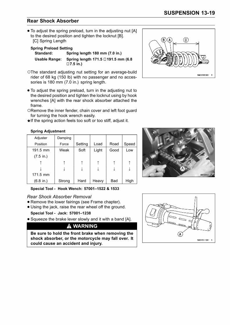
SUSPENSION 13-19
Rear Shock Absorber
•To adjust the spring preload, turn in the adjusting nut [A]to the desired position and tighten the locknut [B].[C] Spring Length
Spring Preload SettingStandard: Spring length 180 mm (7.0 in.)
Usable Range: Spring length 171.5 ∼ 191.5 mm (6.8∼ 7.5 in.)
The standard adjusting nut setting for an average-buildrider of 68 kg (150 lb) with no passenger and no acces-sories is 180 mm (7.0 in.) spring length.
• To adjust the spring preload, turn in the adjusting nut tothe desired position and tighten the locknut using by hookwrenches [A] with the rear shock absorber attached theframe.Remove the inner fender, chain cover and left foot guardfor turning the hook wrench easily.If the spring action feels too soft or too stiff, adjust it.
Spring Adjustment
Adjuster Damping
Position Force Setting Load Road Speed
191.5 mm Weak Soft Light Good Low
(7.5 in.)
↑ ↑ ↑ ↑ ↑ ↑↓ ↓ ↓ ↓ ↓ ↓
171.5 mm
(6.8 in.) Strong Hard Heavy Bad High
Special Tool - Hook Wench: 57001–1522 & 1533
Rear Shock Absorber Removal
•Remove the lower fairings (see Frame chapter).• Using the jack, raise the rear wheel off the ground.Special Tool - Jack: 57001–1238
•Squeeze the brake lever slowly and it with a band [A].WARNING
Be sure to hold the front brake when removing theshock absorber, or the motorcycle may fall over. Itcould cause an accident and injury.

13-20 SUSPENSION
Rear Shock Absorber
•Remove:Lower Shock Absorber Bolt [A]Upper Tie-Rod Bolt [B]
•Remove:Upper Shock Absorber Nut [A]Upper Shock Absorber Bolt [B]
•Remove the shock absorber upward.
Rear Shock Absorber Installation
•Pack the rocker arm needle bearings with grease.• Tighten:Torque - Rear Shock Absorber Nuts: 34 N·m (3.5 kgf·m, 25
ft·lb)Tie-Rod Nuts: 59 N·m (6.0 kgf·m, 43 ft·lb)
Rear Shock Absorber Inspection
•Remove the rear shock absorber.• Visually inspect the following items.Smooth StrokeOil LeakageCrack or DentIf there is any damage to the rear shock absorber, replaceit.
• Visually inspect the rubber bushing.If it show any signs of damage, replace it.
Rear Shock Absorber Scrapping
WARNINGSince the reservoir tank of the rear shock absorbercontains nitrogen gas, do not incinerate the reser-voir tank without first releasing the gas or it mayexplode.
•Remove the valve cap and release the nitrogen gas com-pletely from the gas reservoir.
• Remove the valve [A].WARNING
Since the high pressure gas is dangerous, do notpoint the valve toward your face or body.
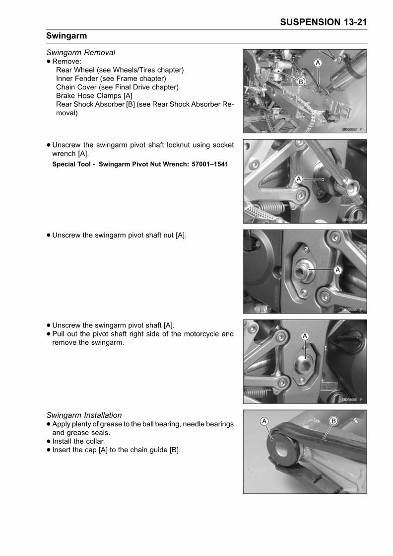
SUSPENSION 13-21
Swingarm
Swingarm Removal
•Remove:Rear Wheel (see Wheels/Tires chapter)Inner Fender (see Frame chapter)Chain Cover (see Final Drive chapter)Brake Hose Clamps [A]Rear Shock Absorber [B] (see Rear Shock Absorber Re-moval)
•Unscrew the swingarm pivot shaft locknut using socketwrench [A].
Special Tool - Swingarm Pivot Nut Wrench: 57001–1541
•Unscrew the swingarm pivot shaft nut [A].
• Unscrew the swingarm pivot shaft [A].
• Pull out the pivot shaft right side of the motorcycle andremove the swingarm.
Swingarm Installation
•Apply plenty of grease to the ball bearing, needle bearingsand grease seals.
• Install the collar.• Insert the cap [A] to the chain guide [B].

13-22 SUSPENSION
Swingarm
•Place the collar [A] on the stopper [B] inside the frame [C].• Insert the pivot shaft into the frame from the right side.• First, tighten the pivot shaft so that the clearance betweenthe collar and the frame come to zero mm (zero in.) [D].
Torque - Swingarm Pivot Shaft (First): 25 N·m (2.5 kgf·m,18 ft·lb)
•Loosen the pivot shaft, and tighten the pivot shaft securelyso that the clearance between the collar and the framecome to zero mm (zero in.) again with specified torque.
Torque - Swinagrm Pivot Shaft (Final)ZX636: 20 N·m (2.0 kgf·m, 14 ft·lb)ZX600: 25 N·m (2.5 kgf·m, 18 ft·lb)
•Tighten the pivot locknut with the swingarm pivot nutwrench.
Special Tool - Swingarm Pivot Nut Wrench: 57001–1541
Torque - Swingarm Pivot Shaft Locknut: 98 N·m (10 kgf·m,72 ft·lb)
•Tighten the pivot shaft nut.Torque - Swingarm Pivot Shaft Nut: 108 N·m (11 kgf·m, 81
ft·lb)
• Install the removed parts (see appropriate chapters).
Swingarm Bearing Removal
•Remove:SwingarmCollar [A]Cap [B]Grease Seals [C]Sleeve [D]Circlip (right side) [E]
Special Tool - Inside Circlip Pliers: 57001–143
•Remove the ball bearing and needle bearings.Special Tool - Oil Seal & Bearing Remover: 57001–1058
[A]

SUSPENSION 13-23
Swingarm
Swingarm Bearing Installation
•Apply plenty of grease to the ball bearing and needlebearings.
• Install the needle bearings so that the manufacturer’smarks faces out.
• Install the ball bearing so that the manufacturer’s marksfaces out.
Special Tool - Bearing Driver Set: 57001–1129 [A]
Swingarm Bearing, Sleeve Inspection
CAUTION
Do not remove the bearings for inspection. Re-moval may damage them.
• Inspect the needle bearings [A] and ball bearing [B] in-stalled in the swingarm.The rollers and ball in a bearing normally wear very little,and wear is difficult to measure. Instead of measuring,visually inspect the bearing for abrasion, discoloration, orother damage.If the needle bearing, ball bearing, and sleeve show anysings of abnormal wear, discoloration, or damage, re-place them as a set.
Swingarm Pivot Lubrication
•Refer to the Suspension in the Periodic Maintenancechapter.
Chain Guide Inspection
•Visually inspect the chain guide [A].Replace the chain slider if it shows any signs of abnormalwear or damage.

13-24 SUSPENSION
Tie-Rod, Rocker Arm
Tie-Rod Removal
•Remove the lower fairings (see Frame chapter).• Squeeze the brake lever slowly and hold it with a band[A].
•Using the jack, raise the rear wheel off the ground.Special Tool - Jack: 57001–1238
•Remove:Upper Tie-Rod Bolt and Nut [A]Lower Tie-Rod Bolt and Nut [B]Tie-Rods [C]
Tie-Rod Installation
•Apply grease to the inside of the needle bearings andgrease seals.
• Install the tie-rods so that the chamfered side faces thebolts and nuts.
• Tighten:Torque - Tie-Rod Nuts: 59 N·m (6.0 kgf·m, 43 ft·lb)
Rocker Arm Removal
•Remove the lower fairings (see Frame chapter)• Squeeze the brake lever slowly and hold it with a band.•Using the jack, raise the rear wheel off the ground.Special Tool - Jack: 57001–1238
•Remove:Lower Rear Shock Absorber Bolt and Nut [A]Lower Tie-Rod Bolt and Nut [B]Rocker Arm Bolt and Nut [C]Rocker Arm [D]
Rocker Arm Installation
•Apply grease to the inside of the needle bearings greaseseals, and add grease to the grease nipple.
• Tighten:Torque - Rocker Arm Nut: 34 N·m (3.5 kgf·m, 25 ft·lb)
Tie-Rod Nut: 59 N·m (6.0 kgf·m, 43 ft·lb)Rear Shock Absorber Nut: 34 N·m (3.5 kgf·m, 25ft·lb)
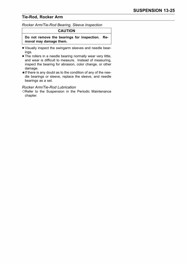
SUSPENSION 13-25
Tie-Rod, Rocker Arm
Rocker Arm/Tie-Rod Bearing, Sleeve Inspection
CAUTION
Do not remove the bearings for inspection. Re-moval may damage them.
•Visually inspect the swingarm sleeves and needle bear-ings.
• The rollers in a needle bearing normally wear very little,and wear is difficult to measure. Instead of measuring,inspect the bearing for abrasion, color change, or otherdamage.If there is any doubt as to the condition of any of the nee-dle bearings or sleeve, replace the sleeve, and needlebearings as a set.
Rocker Arm/Tie-Rod LubricationRefer to the Suspension in the Periodic Maintenancechapter.


STEERING 14-1
14
Steering
Table of Contents
Exploded View........................................................................................................................ 14-2Special Tools .......................................................................................................................... 14-4Steering .................................................................................................................................. 14-5
Steering Inspection ........................................................................................................... 14-5Steering Adjustment.......................................................................................................... 14-5
Steering Stem......................................................................................................................... 14-6Stem, Stem Bearing Removal........................................................................................... 14-6Stem, Stem Bearing Installation........................................................................................ 14-6Stem Bearing Lubrication.................................................................................................. 14-8Steering Stem Warp.......................................................................................................... 14-9
Handlebar ............................................................................................................................... 14-10Handlebar Removal .......................................................................................................... 14-10Handlebar Installation ....................................................................................................... 14-10

14-2 STEERING
Exploded View
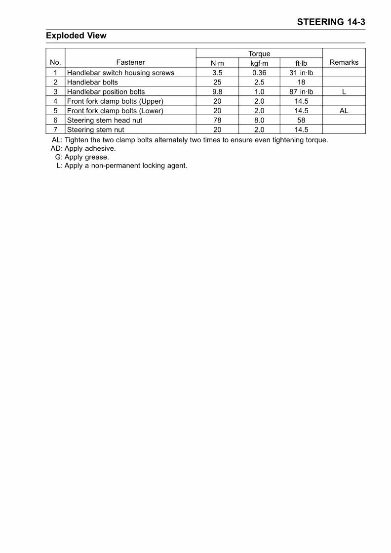
STEERING 14-3
Exploded View
TorqueNo. Fastener N·m kgf·m ft·lb Remarks
1 Handlebar switch housing screws 3.5 0.36 31 in·lb2 Handlebar bolts 25 2.5 183 Handlebar position bolts 9.8 1.0 87 in·lb L4 Front fork clamp bolts (Upper) 20 2.0 14.55 Front fork clamp bolts (Lower) 20 2.0 14.5 AL6 Steering stem head nut 78 8.0 587 Steering stem nut 20 2.0 14.5
AL: Tighten the two clamp bolts alternately two times to ensure even tightening torque.AD: Apply adhesive.G: Apply grease.L: Apply a non-permanent locking agent.

14-4 STEERING
Special Tools
Head Pipe Outer Race Press Shaft:57001–1075
Steering Stem Nut Wrench:57001–1100
Jack:57001–1238
Steering Stem Bearing Driver:57001–1344
Steering Stem Bearing Driver Adapter:57001–1345
Head Pipe Outer Race Driver:57001–1446
Head Pipe Outer Race Driver:57001–1447

STEERING 14-5
Steering
Steering InspectionRefer to the Steering in the Periodic Maintenance chapter.Steering AdjustmentRefer to the Steering in the Periodic Maintenance chapter.

14-6 STEERING
Steering Stem
Stem, Stem Bearing Removal
•Remove:Fairings (see Frame chapter)Fuel Tank (see Fuel System (DFI) chapter)Brake Hose Clamp Bolt [A]Left/Right handlebar Switch Leads Clamp Bolt [A]Clutch Cable Clamp Bolt [B]Front Wheel (see Wheels/Tires chapter)Front Fork (see Suspension chapter)Steering Stem Head Nut and WasherSteering Stem Head and Handlebars
•Pushing up the stem base, and remove the steering stemlock nut[A].
• Bend the claw of lock washer[B] faced steering stem locknut to straight.
Special Tool - Steering Stem Nut Wrench: 57001–1100
•Remove the lock washer, steering stem nut[C] and stemcap[D],then remove the steering stem[E].
•Remove the upper ball bearing inner race.
• To remove the bearing outer races [A] pressed into thehead pipe [B], insert a bar [C] into the recesses [D] of headpipe, and applying it to both recess alternately hammer itto drive the race out.
NOTEIf either steering stem bearing is damaged, it is recom-mended that both the upper and lower bearings (includ-ing outer races) should be replaced with new ones.
•Remove the lower bearing inner race (with its grease seal)which is pressed onto the steering stem with a suitablecommercially available bearing puller.
Stem, Stem Bearing Installation
•Replace the bearing outer races with new ones.• Apply grease to the outer races, and drive them into thehead pipe at the same time.
Special Tools - Head Pipe Outer Race Press Shaft:57001–1075 [A]
Head Pipe Outer Race Drivers: 57001–1446[B]
Head Pipe Outer Race Driver: 57001–1447[C]

STEERING 14-7
Steering Stem
•Replace the bearing inner races with new ones.• Install the oil seal [D] on the steering stem, and drive thelower ball bearing inner race [A] applied the grease ontothe stem.
Special Tools - Steering Stem Bearing Driver: 57001–1344[B]
Steering Stem Bearing Driver Adapter:57001–1345 [C]
• Install the lower ball bearing [A] onto the stem.•Apply grease to the upper ball bearing [B] and inner race[C].
• Install the stem through the head pipe and install the ballbearing and inner race on it.
• Install the stem cap [A], lock washer [B] and steering stemnut [C] and hand tighten it and steering stem lock nut [D].
• Install the stem head.
• Install the washer [E], and tighten the stem head nut [F]lightly.
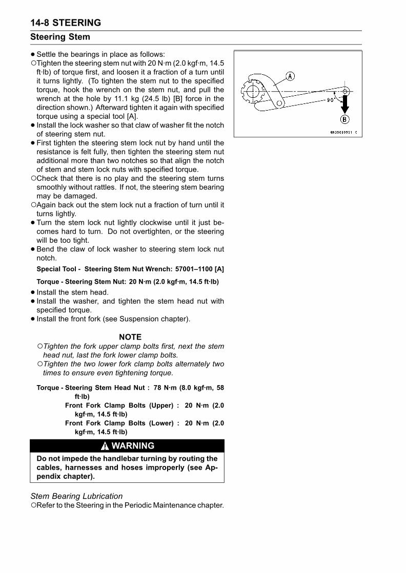
14-8 STEERING
Steering Stem
•Settle the bearings in place as follows:Tighten the steering stem nut with 20 N·m (2.0 kgf·m, 14.5ft·lb) of torque first, and loosen it a fraction of a turn untilit turns lightly. (To tighten the stem nut to the specifiedtorque, hook the wrench on the stem nut, and pull thewrench at the hole by 11.1 kg (24.5 lb) [B] force in thedirection shown.) Afterward tighten it again with specifiedtorque using a special tool [A].
• Install the lock washer so that claw of washer fit the notchof steering stem nut.
• First tighten the steering stem lock nut by hand until theresistance is felt fully, then tighten the steering stem nutadditional more than two notches so that align the notchof stem and stem lock nuts with specified torque.Check that there is no play and the steering stem turnssmoothly without rattles. If not, the steering stem bearingmay be damaged.Again back out the stem lock nut a fraction of turn until itturns lightly.
• Turn the stem lock nut lightly clockwise until it just be-comes hard to turn. Do not overtighten, or the steeringwill be too tight.
• Bend the claw of lock washer to steering stem lock nutnotch.
Special Tool - Steering Stem Nut Wrench: 57001–1100 [A]
Torque - Steering Stem Nut: 20 N·m (2.0 kgf·m, 14.5 ft·lb)
• Install the stem head.
• Install the washer, and tighten the stem head nut withspecified torque.
• Install the front fork (see Suspension chapter).NOTE
Tighten the fork upper clamp bolts first, next the stemhead nut, last the fork lower clamp bolts.Tighten the two lower fork clamp bolts alternately twotimes to ensure even tightening torque.
Torque - Steering Stem Head Nut : 78 N·m (8.0 kgf·m, 58ft·lb)
Front Fork Clamp Bolts (Upper) : 20 N·m (2.0kgf·m, 14.5 ft·lb)
Front Fork Clamp Bolts (Lower) : 20 N·m (2.0kgf·m, 14.5 ft·lb)
WARNINGDo not impede the handlebar turning by routing thecables, harnesses and hoses improperly (see Ap-pendix chapter).
Stem Bearing LubricationRefer to the Steering in the Periodic Maintenance chapter.
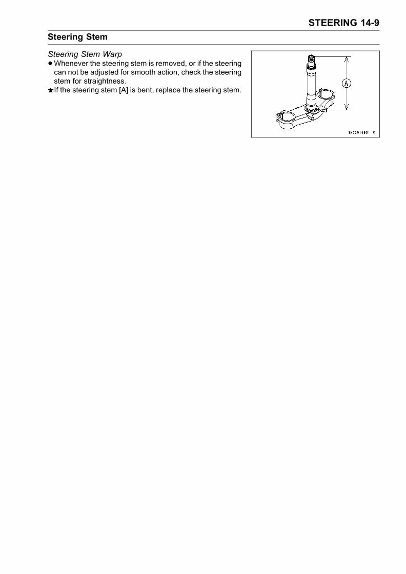
STEERING 14-9
Steering Stem
Steering Stem Warp
•Whenever the steering stem is removed, or if the steeringcan not be adjusted for smooth action, check the steeringstem for straightness.If the steering stem [A] is bent, replace the steering stem.

14-10 STEERING
Handlebar
Handlebar Removal
•Remove:Clutch Lever Assembly [A]Left Handlebar Switch Housing [B]Front Brake Master Cylinder [C]Right handlebar Switch Housing [D]Throttle Case [E]
•Remove:Weight Bolts [A]Handlebar Weight [B]Fitting [C]Clip [D]
•Remove:Steering Stem Head [A]Throttle GripLeft Handlebar GripHandlebar Bolts [B]Handlebar Position Bolt [C]
•Remove the handlebars [D].
Handlebar Installation
•Apply adhesive cement to the inside of the left handlebargrip.
• Apply a non-permanent locking agent to the threads ofthe handlebar position bolts and weight bolts, and tightenthem with specified torque.
Torque - Handlebar Bolts: 25 N·m (2.5 kgf·m, 187 in·lb)Handlebar Position Bolts: 9.8 N·m (1.0 kgf·m, 87in·lb)
• Install the front brake master cylinder (see Brakes chap-ter).
• Install the clutch lever [A] so that the mating surface [B]of the left handlebar switch housing is aligned with themating surface [C] of the clutch lever clamp.
• Tighten the upper clamp bolt first, and then the lowerclamp bolt. There will be a gap at the lower part of theclamp after tightening.
Torque - Clutch Lever Clamp Bolts: 7.8 N·m (0.80 kgf·m, 69in·lb)
Handlebar Switch Housing Screws: 3.5 N·m (0.36kgf·m, 31 in·lb)
• Install the removed parts (see appropriate chapters).
FRAME 15-1
15
Frame
Table of Contents
Exploded View........................................................................................................................ 15-2Seats ...................................................................................................................................... 15-8
Rear Seat Removal........................................................................................................... 15-8Rear Seat Installation........................................................................................................ 15-8Front Seat Removal .......................................................................................................... 15-8Front Seat Installation ....................................................................................................... 15-8
Fairings................................................................................................................................... 15-9Lower Fairing Removal ..................................................................................................... 15-9Inner (Upper) Fairing Removal ......................................................................................... 15-9Inner (Lower) Fairing Removal ......................................................................................... 15-9Upper Fairing Removal ..................................................................................................... 15-9
Seat Cover.............................................................................................................................. 15-11Seat Cover Removal......................................................................................................... 15-11Seat Cover Installation...................................................................................................... 15-11
Fenders .................................................................................................................................. 15-12Front Fender Removal ...................................................................................................... 15-12Front Fender Installation ................................................................................................... 15-12Flap and Rear Fender Rear Removal............................................................................... 15-12Flap and Rear Fender Rear Installation............................................................................ 15-12Rear Fender Front Removal ............................................................................................. 15-13Rear Fender Front Installation .......................................................................................... 15-13Inner Fender Removal ...................................................................................................... 15-13Inner Fender Installation ................................................................................................... 15-13
Frame ..................................................................................................................................... 15-14Rear Frame Removal........................................................................................................ 15-14Rear Frame Installation..................................................................................................... 15-14Frame Inspection .............................................................................................................. 15-14
Storage Box............................................................................................................................ 15-15Storage Box Removal ....................................................................................................... 15-15Storage Box Installation .................................................................................................... 15-15
Side Stand .............................................................................................................................. 15-16Side Stand Removal ......................................................................................................... 15-16Side Stand Installation ...................................................................................................... 15-16

15-2 FRAME
Exploded View

FRAME 15-3
Exploded View
TorqueNo. Fastener N·m kgf·m ft·lb Remarks
1 Footpeg stay bolts 25 2.5 182 Footpeg holder bolts 34 3.5 25 L3 Rear frame bolts 59 6.0 434 Side stand bracket bolts 49 5.0 365 Side stand bolt 44 4.5 32 G6 Side stand switch bolt 8.8 0.90 78 in·lb L
G: Apply grease.L: Apply a non-permanent locking agent.

15-4 FRAME
Exploded View

FRAME 15-5
Exploded View
TorqueNo. Fastener N·m kgf·m ft·lb Remarks
1 Wind shield mounting screws 0.4 0.04 3.5 in·lb2 Front fender mounting bolts 3.9 0.40 35 in·lb
3. United States and Canada ModelsL: Apply a non-permanent locking agent.

15-6 FRAME
Exploded View

FRAME 15-7
Exploded View
1. United States and Canada Models

15-8 FRAME
Seats
Rear Seat Removal
• Insert the ignition switch key into the seat lock [A], turningthe key counterclockwise, pulling the rear of the seat [B]up, and pull the seat backward.
Rear Seat Installation
•Slip the rear seat hooks [A] into the slend holes [B] on theframe.
• Insert the seat pin [C] into the latch hole [D].• Push down the rear part of the seat until the lock clicks.
Front Seat Removal
•Remove:Rear Seat (see Rear Seat Removal)Mounting Bolt [A]Set Bracket (rear) [B]
•Remove the front seat [C] by pulling the rear of it up andbackward.
Front Seat Installation
•Slip the front seat hook [A] under the brace [B] of the seatbracket (front).

FRAME 15-9
Fairings
Lower Fairing Removal
•Remove:Allen Bolts [A] [B] [C] [D] [E]Rivet Screws [F]
• Pull the lower front part of the lower fairing outward toclear the stoppers [G].
•Remove the lower fairing.•Remove the other side lower fairing in the same manner.
NOTEWhen removing the left and right lower fairings at thesame time, do not remove the screws [D] (both sides)and bottom of stoppers [G].
Inner (Upper) Fairing Removal
•Remove the allen bolts [A].• Pull the inner (upper) fairing upward [B] to clear the stop-pers [C].
Inner (Lower) Fairing Removal
•Remove:Lower Fairing (Left or Right)Other Side Inner Fairing Bolt [A]Inner (Lower) Fairing [B]
Upper Fairing Removal
•Remove:Inner (Upper) Fairings [A]Allen Bolts [B] (Left and Right)

15-10 FRAME
Fairings
•Remove:Nuts [A] (Left and Right)Rear View Mirrors [B] (Left and Right)
•Remove:Headlight Lead Connector [A]Turn Signal Light Lead Connector [B]Upper Fairing

FRAME 15-11
Seat Cover
Seat Cover Removal
•Remove:SeatsScrews and Washers [A]Rivet Screws [B] (Left and Right)
• Pull the seat cover backward to clear the stoppers [C].
Seat Cover Installation
•Set the seat cover [A], and insert the rivet screws [B] intothe holes in the seat cover and rear fender rear.
• Screw in the pins [C] into the rivet.• Fit the projection [D] on the seat cover into the rear framebracket.
• Tighten the screws [E].• Install the seats.

15-12 FRAME
Fenders
Front Fender Removal
•Remove:Brake Hose Clamps [A] (Left and Right)Bolts [B] (Left and Right)
•Remove the front fender [C].
Front Fender Installation
• Install the front fender to the front fork.• Tighten:Torque - Front Fender Mounting Bolts: 3.9 N·m (0.40 kgf·m,
35 in·lb)
• Install the brake hose clamps to the front fender holes.Flap and Rear Fender Rear Removal
•Remove:Seats (see Rear/Front Seat Removal)Seat Cover (see Seat Cover Removal)Storage Box (see Storage Box Removal)
•Disconnect:Rear Turn Signal Light Lead Connectors [A] (Left andRight)License Light Lead Connector [B]Tail/Brake Light Lead Connector [C]
•Remove:Allen Bolts [D]Nuts [E]Seat Lock Bolts [F]
•Remove the rivet screws [A] to take off the brackets [B]and flap [C] assembled the rear turn signals and licenselight.
• Pull out the rear fender rear [D] assembled tail/brake lightdownward.
Flap and Rear Fender Rear Installation
• Insert the projection of rear fender rear under the rearfender front.
• Install the front part of the flap under the rear fender rear.• Install the harness clamp in accordance with HarnessRouting section in Appendix chapter.
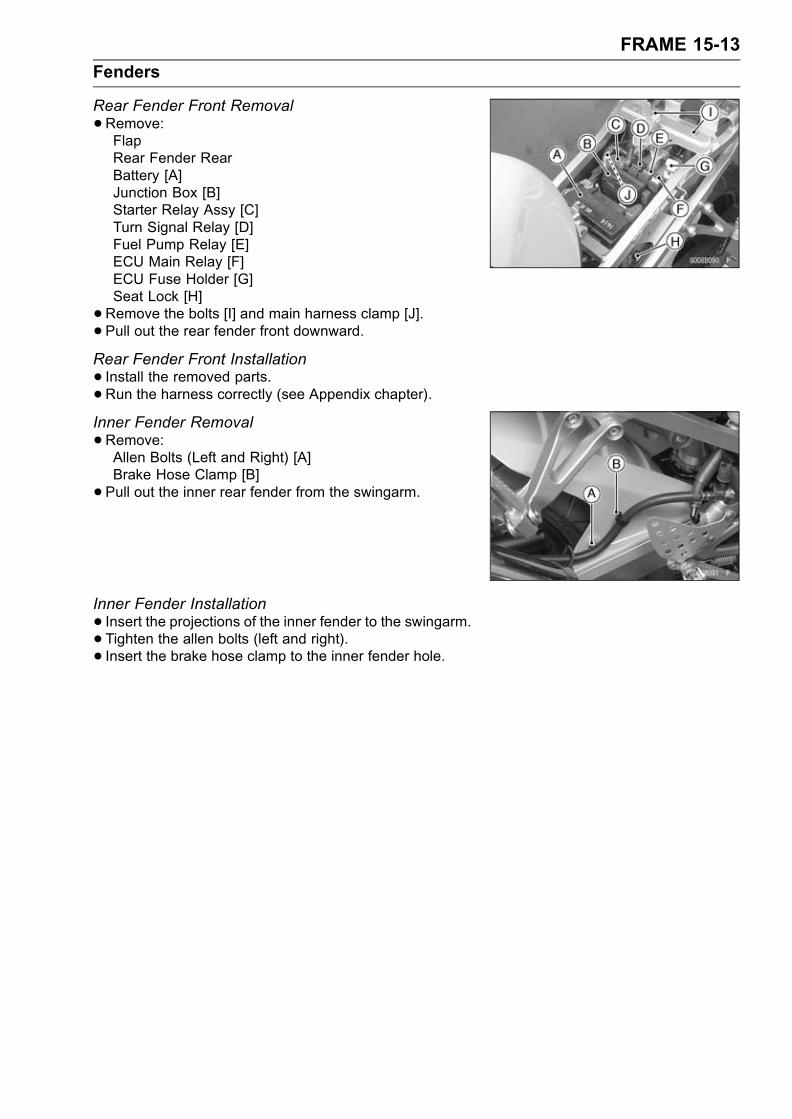
FRAME 15-13
Fenders
Rear Fender Front Removal
•Remove:FlapRear Fender RearBattery [A]Junction Box [B]Starter Relay Assy [C]Turn Signal Relay [D]Fuel Pump Relay [E]ECU Main Relay [F]ECU Fuse Holder [G]Seat Lock [H]
•Remove the bolts [I] and main harness clamp [J].• Pull out the rear fender front downward.Rear Fender Front Installation
• Install the removed parts.•Run the harness correctly (see Appendix chapter).Inner Fender Removal
•Remove:Allen Bolts (Left and Right) [A]Brake Hose Clamp [B]
• Pull out the inner rear fender from the swingarm.
Inner Fender Installation
• Insert the projections of the inner fender to the swingarm.• Tighten the allen bolts (left and right).• Insert the brake hose clamp to the inner fender hole.
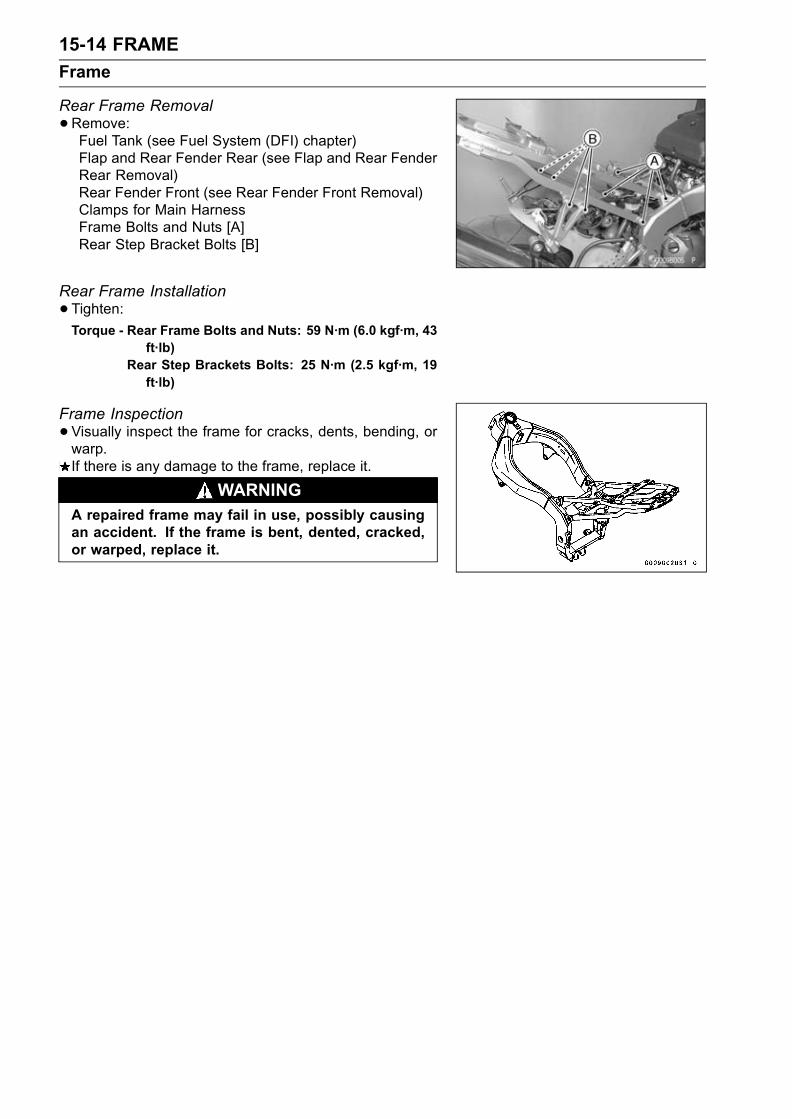
15-14 FRAME
Frame
Rear Frame Removal
•Remove:Fuel Tank (see Fuel System (DFI) chapter)Flap and Rear Fender Rear (see Flap and Rear FenderRear Removal)Rear Fender Front (see Rear Fender Front Removal)Clamps for Main HarnessFrame Bolts and Nuts [A]Rear Step Bracket Bolts [B]
Rear Frame Installation
•Tighten:Torque - Rear Frame Bolts and Nuts: 59 N·m (6.0 kgf·m, 43
ft·lb)Rear Step Brackets Bolts: 25 N·m (2.5 kgf·m, 19ft·lb)
Frame Inspection
•Visually inspect the frame for cracks, dents, bending, orwarp.If there is any damage to the frame, replace it.
WARNINGA repaired frame may fail in use, possibly causingan accident. If the frame is bent, dented, cracked,or warped, replace it.

FRAME 15-15
Storage Box
Storage Box Removal
•Remove:Seat Cover (see this chapter)Screw [A]
• Pulling up the rear part of the box backward.
Storage Box Installation
• Insert the front part [A] of the box into the rear frame [B].• Tighten the screws.
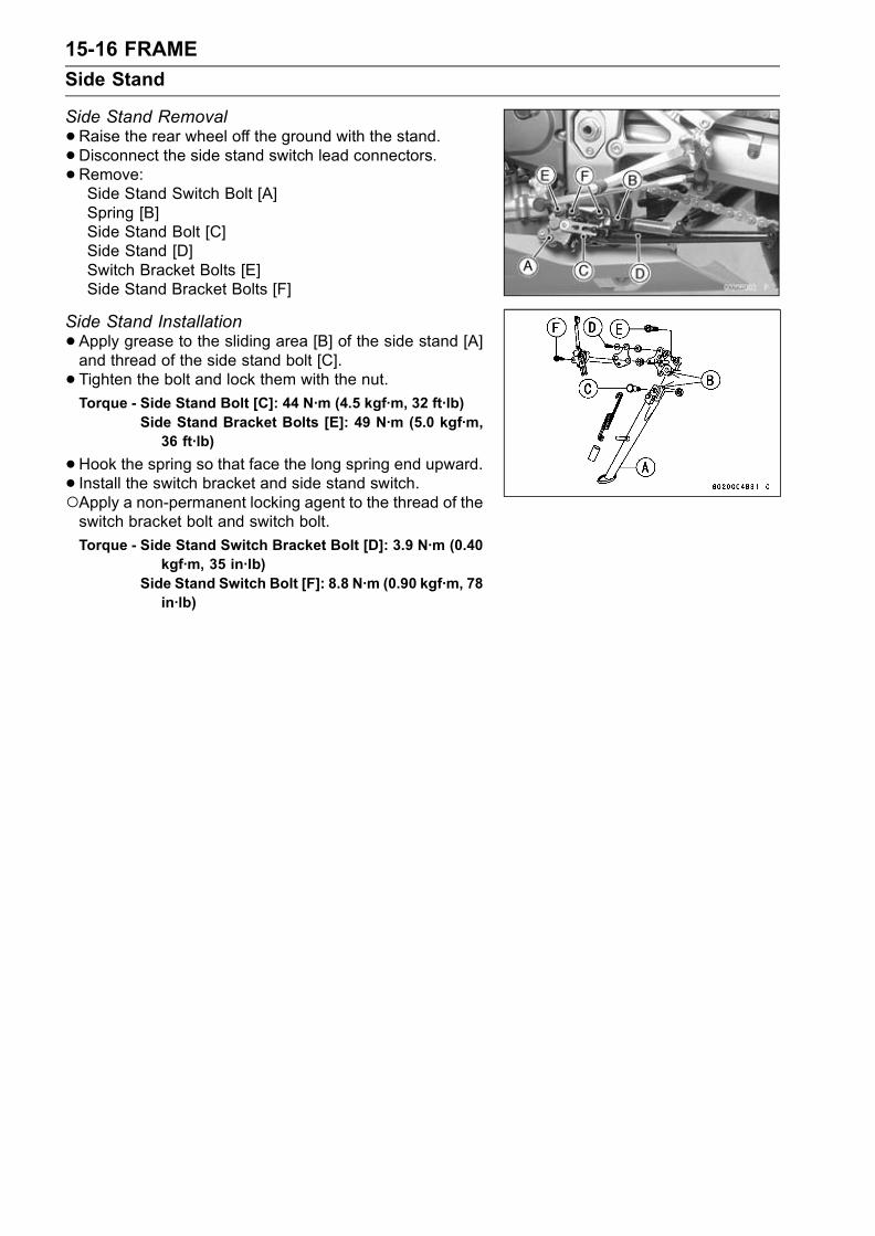
15-16 FRAME
Side Stand
Side Stand Removal
•Raise the rear wheel off the ground with the stand.•Disconnect the side stand switch lead connectors.•Remove:Side Stand Switch Bolt [A]Spring [B]Side Stand Bolt [C]Side Stand [D]Switch Bracket Bolts [E]Side Stand Bracket Bolts [F]
Side Stand Installation
•Apply grease to the sliding area [B] of the side stand [A]and thread of the side stand bolt [C].
• Tighten the bolt and lock them with the nut.
Torque - Side Stand Bolt [C]: 44 N·m (4.5 kgf·m, 32 ft·lb)Side Stand Bracket Bolts [E]: 49 N·m (5.0 kgf·m,36 ft·lb)
•Hook the spring so that face the long spring end upward.• Install the switch bracket and side stand switch.Apply a non-permanent locking agent to the thread of theswitch bracket bolt and switch bolt.
Torque - Side Stand Switch Bracket Bolt [D]: 3.9 N·m (0.40kgf·m, 35 in·lb)
Side Stand Switch Bolt [F]: 8.8 N·m (0.90 kgf·m, 78in·lb)

ELECTRICAL SYSTEM 16-1
16
Electrical System
Table of Contents
Exploded View................................... 16-4Wiring Diagram (United States andCanada) .......................................... 16-10
Wiring Diagram (Australia) ................ 16-12Wiring Diagram (Other than UnitedStates, Canada and Australia)........ 16-14
Specifications .................................... 16-16Special Tools and Sealant ................. 16-17Parts Location.................................... 16-18Precautions........................................ 16-20Electrical Wiring................................. 16-22
Wiring Inspection ......................... 16-22Battery ............................................... 16-23
Battery Removal .......................... 16-23Electrolyte Filling.......................... 16-23Initial Charge................................ 16-24Precautions .................................. 16-24Interchange .................................. 16-25Charging Condition Inspection..... 16-25Refreshing Charge....................... 16-26
Charging System............................... 16-28Alternator Cover Removal............ 16-28Alternator Cover Installation......... 16-28Stator Coil Removal ..................... 16-28Stator Coil Installation .................. 16-28Alternator Rotor Removal ............ 16-29Alternator Rotor Installation ......... 16-29Alternator Inspection .................... 16-31Regulator/Rectifier Inspection...... 16-32Charging Voltage Inspection ........ 16-35
Ignition System.................................. 16-37Crankshaft Sensor Removal ........ 16-38Crankshaft Sensor Installation ..... 16-39Crankshaft Sensor Inspection...... 16-39Crankshaft Sensor Peak Voltage . 16-40Stick Coil (Ignition Coil togetherwith Spark Plug Cap) Removal . 16-40
Stick Coil (Ignition Coil togetherwith Spark Plug Cap)Installation ................................. 16-40
Stick Coil (Ignition Coil togetherwith Spark Plug Cap) Inspection 16-41
Stick Coil Primary Peak Voltage .. 16-41Spark Plug Removal .................... 16-42Spark Plug Installation ................. 16-42
Spark Plug Cleaning andInspection.................................. 16-42
Spark Plug Gap Inspection .......... 16-42Camshaft Position SensorRemoval .................................... 16-43
Camshaft Position SensorInstallation ................................. 16-43
Camshaft Position SensorInspection.................................. 16-43
Camshaft Position Sensor PeakVoltage Inspection..................... 16-44
Interlock Operation Inspection ..... 16-45IC Igniter Inspection ..................... 16-46
Electric Starter System...................... 16-48Starter Motor Removal................. 16-48Starter Motor Installation.............. 16-48Starter Motor Disassembly........... 16-48Starter Motor Assembly ............... 16-48Brush Inspection .......................... 16-49Commutator Cleaning andInspection.................................. 16-50
Armature Inspection..................... 16-50Brush Lead Inspection ................. 16-50Right–hand End Cover AssemblyInspection.................................. 16-51
Starter Relay Inspection............... 16-51Lighting System................................. 16-53
Headlight Beam HorizontalVertical Adjustment ................... 16-53
Headlight Bulb Replacement ....... 16-54Turn Signal Relay Inspection ....... 16-56
Radiator Fan System......................... 16-58Fan System Circuit Inspection ..... 16-58Fan Motor Inspection ................... 16-58
Meter ................................................. 16-60Meter Assembly Removal ............ 16-60Meter Assembly Disassembly...... 16-60
Meter, Gauge, Indicator Unit.............. 16-61Electronic Combination MeterAssembly Inspection ................. 16-61
Switches and Sensors ....................... 16-69Brake Light Timing Inspection...... 16-69Brake Light Timing Adjustment .... 16-69Switch Inspection ......................... 16-69Radiator Fan Switch Inspection ... 16-70

16-2 ELECTRICAL SYSTEM
Water Temperature SensorInspection.................................. 16-71
Speed Sensor Removal ............... 16-71Speed Sensor Installation ............ 16-72Speed Sensor Inspection............. 16-72Fuel Reserve Switch Inspection(1).............................................. 16-72
Fuel Reserve Switch Inspection(2).............................................. 16-73
Junction Box...................................... 16-74Junction Box Fuse CircuitInspection.................................. 16-74
Starter Circuit/Headlight RelayInspection.................................. 16-74
Diode Circuit Inspection ............... 16-75Fuse................................................... 16-77
30 A Main Fuse Removal............. 16-77Junction Box Fuse Removal ........ 16-7715A ECU Fuse Removal.............. 16-77Fuse Installation........................... 16-77Fuse Inspection............................ 16-77


16-4 ELECTRICAL SYSTEM
Exploded View
ELECTRICAL SYSTEM 16-5
Exploded View
TorqueNo. Fastener N·m kgf·m ft·lb Remarks
1 Crankshaft sensor cover bolts 9.8 1.0 87 in·lb L (1)2 Spark plugs 13 1.3 113 in·lb3 Crankshaft sensor bolts 5.9 0.60 52 in·lb4 Timing rotor bolt 44 4.5 335 Tail/Brake light mounting screws 1.2 0.12 10 in·lb6 License light mounting screws 1.2 0.12 10 in·lb7 License light assembly screws 1.0 0.10 8.7 in·lb8 Camshaft position sensor bolt 12 1.2 106 in·lb
9. Camshaft Position Sensor10. Stick Coils11. Crankshaft Sensor12. ECU (Electronic Control Unit)13. Turn Signal Relay14. Fuel Pump Relay15. ECU Main RelayL: Apply a non-permanent locking agent.
SS: Apply silicone sealant.
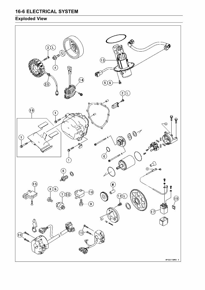
16-6 ELECTRICAL SYSTEM
Exploded View

ELECTRICAL SYSTEM 16-7
Exploded View
TorqueNo. Fastener N·m kgf·m ft·lb Remarks
1 Alternator cover bolt 12 1.2 104 in·lb2 Alternator lead holding plate bolts 6.9 0.70 61 in·lb L3 Stator coil bolts 12 1.2 110 in·lb L4 Alternator rotor bolt 120 12 875 Fuel pump bolts 9.8 1.0 87 in·lb S6 Neutral switch 15 1.5 117 Oil pressure switch 15 1.5 11 SS8 Oil pressure switch terminal bolt 1.5 0.15 13 in·lb G9 Front brake light switch screw 1.2 0.12 10 in·lb10 Handlebar switch housing screws 3.5 0.36 31 in·lb11 Starter motor mounting bolts 9.8 1.0 87 L12 Starter motor clutch bolts 33 3.4 24 L
13. Fuel Pump14. Regulator/Rectifier15. Starter Lockout Switch16. Front Brake Light Switch17. Starter Relay18. Main Fuse19. California ModelL: Apply a non-permanent locking agent.
SS: Apply silicone sealant.M: Apply molybdenum disulfide grease.G: Apply grease or engine oil.S: Follow the specified tightening sequence.
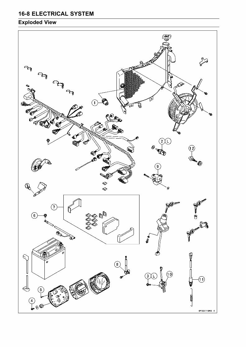
16-8 ELECTRICAL SYSTEM
Exploded View

ELECTRICAL SYSTEM 16-9
Exploded View
TorqueNo. Fastener N·m kgf·m ft·lb Remarks
1 Fan switch 18 1.8 132 Water temperature sensor 25 2.5 18 L3 Side Stand Switch Bolt 8.8 0.90 78 in·lb L4 Meter screws 1.2 0.12 10 in·lb5 Meter assembly screws 1.2 0.12 10 in·lb6 Engine Ground Lead Terminal Bolt 9.8 1.0 87 in·lb
7. Junction Box8. Speed Sensor9. Vehicle-down Sensor10. Side Stand Switch11. Rear Brake Light Switch12. Air Temperature SensorL: Apply a non-permanent locking agent.
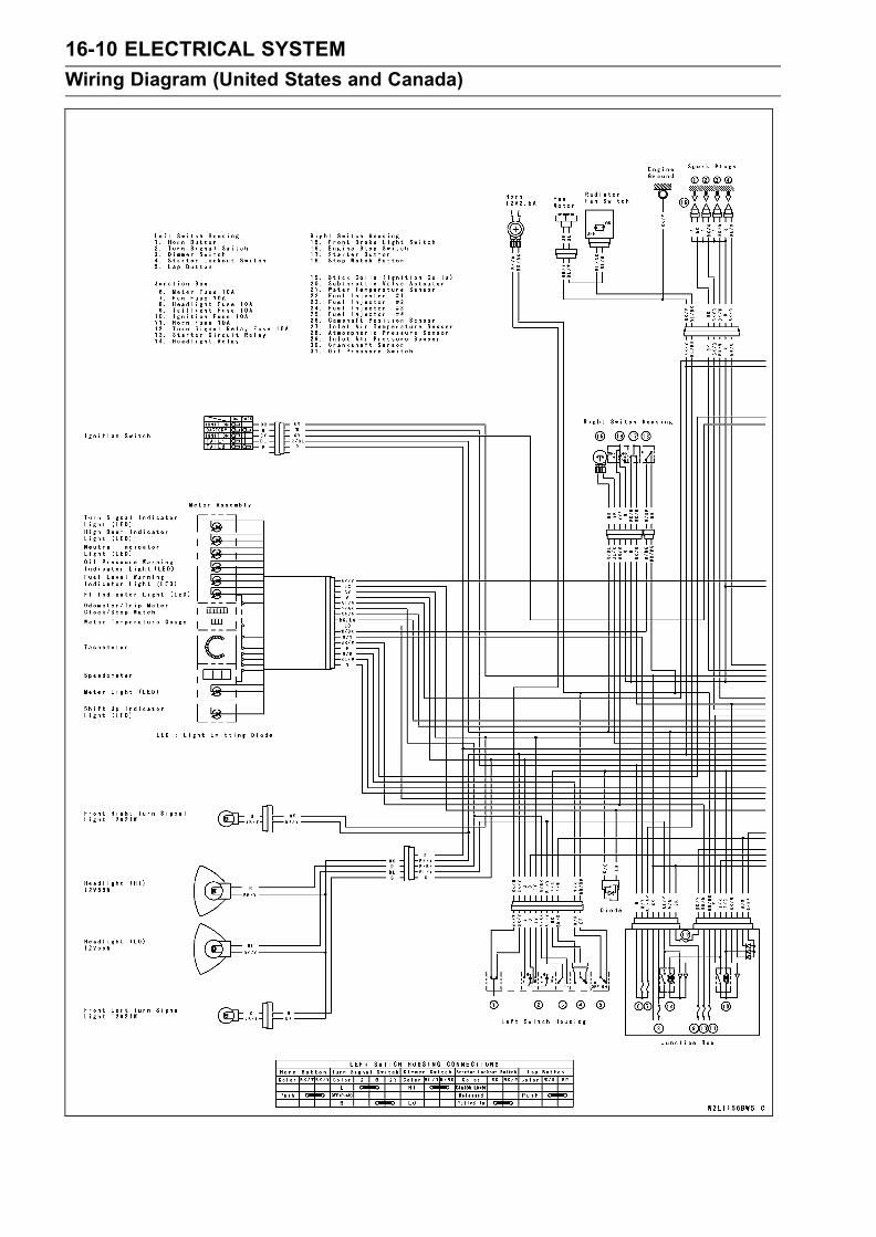
16-10 ELECTRICAL SYSTEM
Wiring Diagram (United States and Canada)
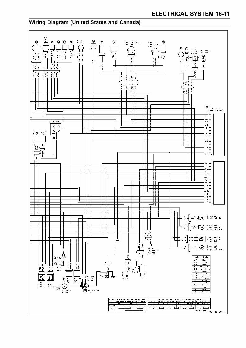
ELECTRICAL SYSTEM 16-11
Wiring Diagram (United States and Canada)

16-12 ELECTRICAL SYSTEM
Wiring Diagram (Australia)

ELECTRICAL SYSTEM 16-13
Wiring Diagram (Australia)

16-14 ELECTRICAL SYSTEM
Wiring Diagram (Other than United States, Canada and Australia)
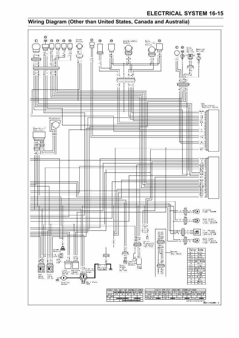
ELECTRICAL SYSTEM 16-15
Wiring Diagram (Other than United States, Canada and Australia)

16-16 ELECTRICAL SYSTEM
Specifications
Item Standard
Battery:
Type Sealed Battery
Capacity 12 V 8 Ah
Voltage 12.6 V or more
Charging System:
Type Three–phase AC
Alternator output voltage 42.4 ∼ 63.6 V @4 000 r/min (rpm)Stator coil resistance 0.3 ∼ 0.4 ΩCharging voltage
(regulator/rectifier output voltage) 14.2 ∼ 15.2 VIgnition System:
Crankshaft sensor resistance 460 ∼ 470 ΩCrankshaft sensor peak voltage 2.0 V or more
Camshaft Position Sensor Resistance 490 ∼ 590 ΩCamshaft Position Sensor Peak Voltage 0.135 V or more
Interlock Operation Voltage 4 V or more
Stick coil:
Primary winding resistance 1.2 ∼ 1.6 ΩSecondary winding resistance 8.5 ∼ 11.5 kΩPrimary peak voltage 100 V or more
Electric Starter System:
Starter motor:
Brush length 7 mm (0.28 in.), Service Limit 3.5 mm (0.14 in.)
Commutator diameter 24 mm (0.94 in.), Service Limit 23 mm (0.91 in.)
Switch and Sensor:
Rear brake light switch timing ON after about 10 mm (0.39 in) pedal travel
Engine oil pressure switch connections When engine is stopped: ON
When engine is running: OFF
Fan switch resistance:
Rising temperature From OFF to ON @ 93 ∼ 103°C (199 ∼ 217°F)Falling temperature Fan stops with the temperature 3 ∼ 8°C (38 ∼ 46°F)
lower than the operation temperature range.
ON: Less than 0.5 ΩOFF: More than 10 MΩ
Water temperature sensor resistance in the text

ELECTRICAL SYSTEM 16-17
Special Tools and Sealant
Flywheel Holder:57001–1313
Hand Tester:57001–1394
Flywheel Puller Assembly:57001–1405
Lead Wire – Peak Voltage Adapter:57001–1449
Needle Adapter Set:57001–1457
Harness Adapter:57001–1542
Kawasaki Bond (Silicone sealant) :56019–120
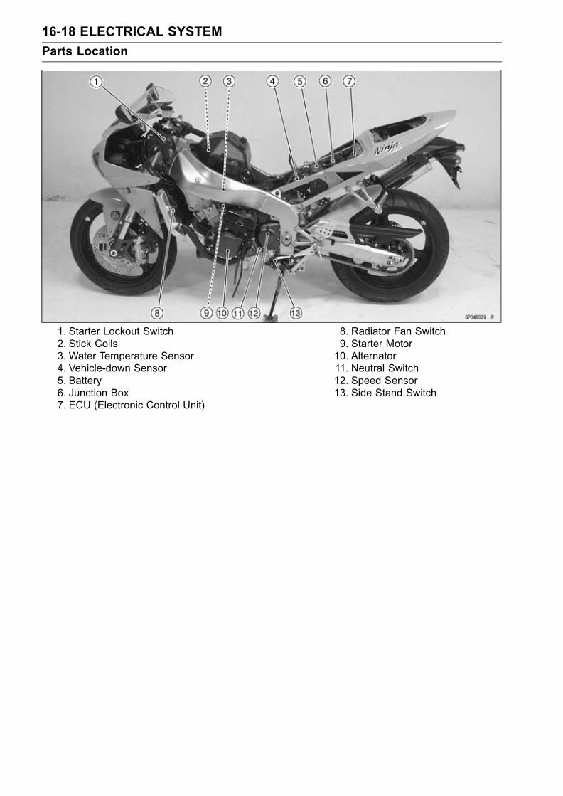
16-18 ELECTRICAL SYSTEM
Parts Location
1. Starter Lockout Switch2. Stick Coils3. Water Temperature Sensor4. Vehicle-down Sensor5. Battery6. Junction Box7. ECU (Electronic Control Unit)
8. Radiator Fan Switch9. Starter Motor10. Alternator11. Neutral Switch12. Speed Sensor13. Side Stand Switch

ELECTRICAL SYSTEM 16-19
Parts Location
1. Starter Relay and Main Fuse2. Turn Signal Relay3. Fuel Pump Relay4. ECU Fuse5. ECU Main Relay6. Inlet Air Pressure Sensor
7. Front Brake Light Switch8. Rear Brake Light Switch9. Regulator/Rectifire10. Crankshaft Sensor11. Oil Pressure Switch12. Camshaft Position Sensor

16-20 ELECTRICAL SYSTEM
Precautions
There are a number of important precautions that aremusts when servicing electrical systems. Learn and ob-serve all the rules below.Do not reverse the battery lead connections. This willburn out the diodes on the electrical parts.Always check battery condition before condemning otherparts of an electrical system. A fully charged battery is amust for conducting accurate electrical system tests.The electrical parts should never be struck sharply, aswith a hammer, or allowed to fall on a hard surface. Sucha shock to the parts can damage them.To prevent damage to electrical parts, do not disconnectthe battery leads or any other electrical connections whenthe ignition switch is on, or while the engine is running.Because of the large amount of current, never keep thestarter button pushed when the starter motor will not turnover, or the current may burn out the starter motor wind-ings.Do not use a meter illumination bulb rated for other thanvoltage or wattage specified in the wiring diagram, as themeter or gauge panel could be warped by excessive heatradiated from the bulb.Take care not to short the leads that are directly con-nected to the battery positive (+) terminal to the chassisground.Troubles may involve one or in some cases all items.Never replace a defective part without determining whatCAUSED the failure. If the failure was caused by someother item or items, they must be repaired or replaced, orthe new replacement will soon fail again.Make sure all connectors in the circuit are clean and tight,and examine wires for signs of burning, fraying, etc. Poorwires and bad connections will affect electrical system op-eration.Measure coil and winding resistance when the part is cold(at room temperature).Color Codes:
BK Black G Green P Pink
BL Blue GY Gray PU Purple
BR Brown LB Light blue R Red
CH Chocolate LG Light green W White
DG Dark green O Orange Y Yellow
Electrical ConnectorsFemale Connectors [A]

ELECTRICAL SYSTEM 16-21
Precautions
Male Connectors [B]

16-22 ELECTRICAL SYSTEM
Electrical Wiring
Wiring Inspection
•Visually inspect the wiring for signs of burning, fraying,etc.If any wiring is poor, replace the damaged wiring.
• Pull each connector [A] apart and inspect it for corrosion,dirt, and damage.If the connector is corroded or dirty, clean it carefully. If itis damaged, replace it.
• Check the wiring for continuity.Use the wiring diagram to find the ends of the lead whichis suspected of being a problem.Connect the hand tester between the ends of the leads.Special Tool - Hand Tester: 57001–1394
Set the tester to the × 1 Ω range, and read the tester.If the tester does not read 0 Ω, the lead is defective. Re-place the lead or the wiring harness [B] if necessary.
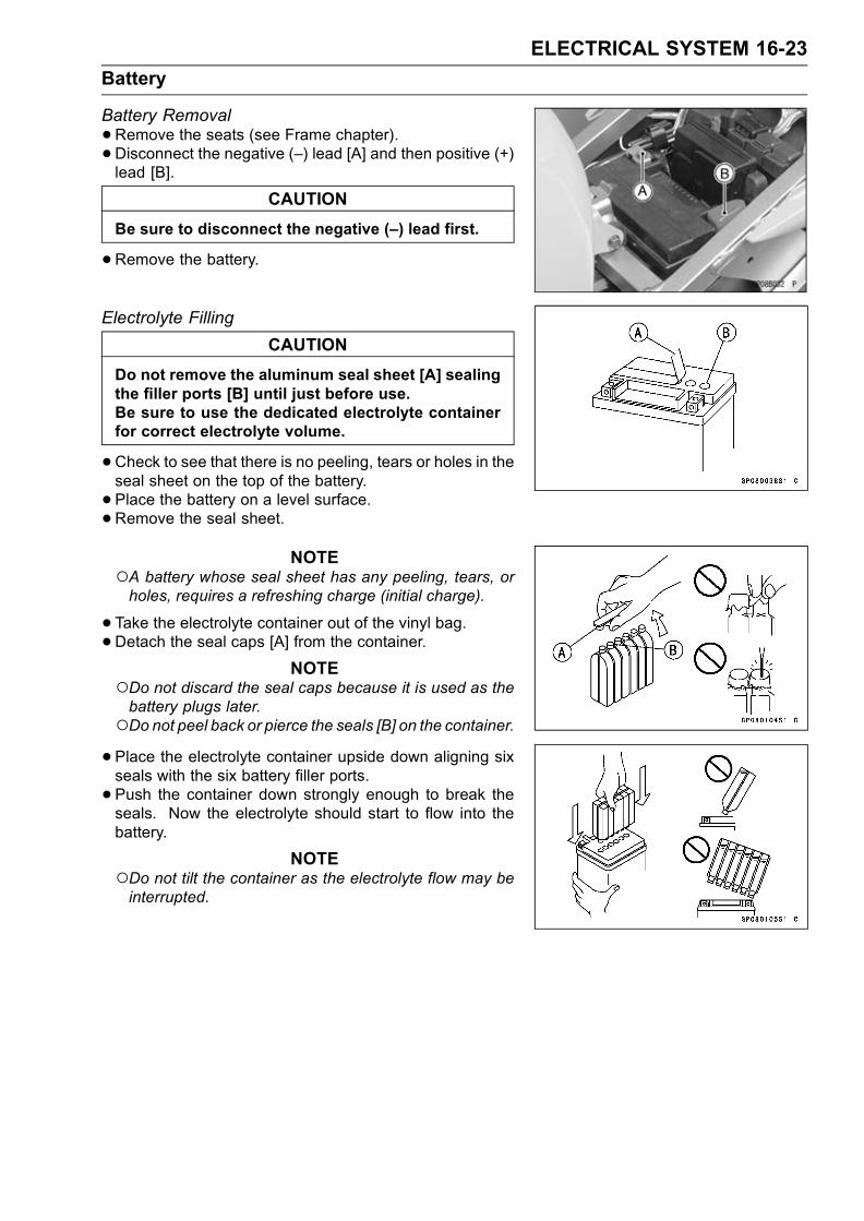
ELECTRICAL SYSTEM 16-23
Battery
Battery Removal
•Remove the seats (see Frame chapter).• Disconnect the negative (–) lead [A] and then positive (+)lead [B].
CAUTION
Be sure to disconnect the negative (–) lead first.
•Remove the battery.
Electrolyte Filling
CAUTION
Do not remove the aluminum seal sheet [A] sealingthe filler ports [B] until just before use.Be sure to use the dedicated electrolyte containerfor correct electrolyte volume.
•Check to see that there is no peeling, tears or holes in theseal sheet on the top of the battery.
• Place the battery on a level surface.•Remove the seal sheet.
NOTEA battery whose seal sheet has any peeling, tears, orholes, requires a refreshing charge (initial charge).
•Take the electrolyte container out of the vinyl bag.•Detach the seal caps [A] from the container.
NOTEDo not discard the seal caps because it is used as thebattery plugs later.Do not peel back or pierce the seals [B] on the container.•Place the electrolyte container upside down aligning sixseals with the six battery filler ports.
• Push the container down strongly enough to break theseals. Now the electrolyte should start to flow into thebattery.
NOTEDo not tilt the container as the electrolyte flow may beinterrupted.

16-24 ELECTRICAL SYSTEM
Battery
•Make sure air bubbles [A] are coming up from all six fillerports.Leave the container this way for 5 minutes or longer.
NOTEIf no air bubbles are coming up from a filler port, tap [B]the bottom of the container two or three times. Neverremove the container from the battery.
CAUTION
Fill the electrolyte into battery until the container iscompletely emptied.
•Be certain that all the electrolyte has flowed out.• Tap the bottom the same way as above if there is anyelectrolyte left in the container.
•Now pull the container gently out of the battery.• Let the battery sit for 20 minutes. During this time, theelectrolyte permeates the special separators and the gasgenerated by chemical reaction is released.
• Fit the seal caps [A] tightly into the filler ports until the sealcap is at the same level as the top of the battery.
NOTEDo not hammer. Press down evenly with both hands.
CAUTION
Once you install the seal caps after filling the bat-tery, never remove it, nor add any water or elec-trolyte.
Initial ChargeWhile a sealed battery can be used after only filling with electrolyte, a battery may not be able to
sufficiently move a starter motor to start an engine in the cases shown in the table below, where aninitial charge is required before use. However, if a battery shows a terminal voltage of higher than12.6 V after 10 minutes of filling (Note 1), no initial charge is necessary.
Condition requiring initial charge Charging method
At low temperatures (lower than 0°C) 0.9 A × 2 ∼ 3 hoursBattery has been stored in high temperature and humidity.
Seal has been removed, or broken - peeling, tear or hole.
Battery as old as 2 years or more after manufacture. 0.9 A × 15 ∼ 20 hoursBattery manufacturing date is printed on battery top.
Example) 12 10 93 T1
Day Month Year Mfg. location
Note 1 : Terminal voltage – To measure battery terminal voltage, use a digital voltmeter.Precautions1) No need of topping-upNo topping-up is necessary in this battery until it ends its life under normal use. Forcibly prying off theseal cap to add water is very dangerous. Never do that.2) Refreshing charge
If an engine will not start, a horn sounds weak, or lamps are dim, it indicates the battery has beendischarged. Give refresh charge for 5 to 10 hours with charge current shown in the specification(see the this chapter).

ELECTRICAL SYSTEM 16-25
Battery
When a fast charge is inevitably required, do it following precisely the maximum charge currentand time conditions indicated on the battery.
CAUTION
This battery is designed to sustain no unusual deterioration if refresh-charged accordingto the method specified above. However, the battery’s performance may be reduced no-ticeably if charged under conditions other than given above.Never remove the seal cap during refresh charge.If by chance an excessive amount of gas is generated due to overcharging, the safety valveoperates to keep the battery safe.
3) When you do not use the motorcycle for monthsGive a refresh charge before you store the motorcycle and store it with the negative lead re-
moved. Give a refresh charge once a month during storage.4) Battery life
If the battery will not start the engine even after several refresh charges, the battery has ex-ceeded its useful life. Replace it. (Provided, however, the vehicle’s starting system has no prob-lem.)
WARNINGKeep the battery away from sparks and open flames during charging, since the batterygives off an explosive gas mixture of hydrogen and oxygen. When using a battery charger,connect the battery to the charger before turning on the charger. This procedure preventssparks at the battery terminals which could ignite any battery gases.No fire should be drawn near the battery, or no terminals should have the tightening loos-ened.The electrolyte contains sulfuric acid. Be careful not to have it touch your skin or eyes. Iftouched, wash it off with liberal amount of water. Get medical attention if severe.
InterchangeA sealed battery can fully display its performance only when combined with a proper vehicle electric
system. Therefore, replace a sealed battery only on a motorcycle which was originally equipped witha sealed battery.Be careful, if a sealed battery is installed on a motorcycle which had an ordinary battery as original
equipment, the sealed battery’s life will be shortened.
Charging Condition InspectionBattery charging condition can be checked by measuring
battery terminal voltage.
•Remove the seats (see Frame chapter).• Disconnect the battery leads.
CAUTION
Be sure to disconnect the negative (–) lead first.
•Measure the battery terminal voltage.

16-26 ELECTRICAL SYSTEM
Battery
NOTEMeasure with a digital voltmeter [A] which can be readto one decimal place voltage.
If the reading is below the specified, refreshing charge isrequired.
Battery Terminal VoltageStandard: 12.6 V or more
Refreshing Charge
•Remove the battery [A].• Do refresh-charge by following method according to thebattery terminal voltage.
WARNINGThis battery is sealed type. Never remove seal caps[B] even at charging. Never add water. Charge withcurrent and time as stated below.
Terminal Voltage: 11.5 ∼ less than 12.6 VStandard Charge
0.9 A × 5 ∼ 10 h (see following chart)Quick Charge
4.0 A × 1.0 h
CAUTION
If possible, do not quick charge. If the quick chargeis done due to unavoidable circumstances, do stan-dard charge later on.
Terminal Voltage : less than 11.5 VCharging Method : 0.9 A × 20 h
NOTEIf the current does not flow when charging, raise thevoltage initially (25 V as maximum), and let down thevoltage to charge when the current starts to flow as ayardstick. If ammeter shows no change in current after5 minutes, you need a new battery. The current, if it canflow into the battery, tends to become excessive. Adjustthe voltage as often as possible to keep the current atstandard value (0.9 A).
Battery [A]Battery Charger [B]Standard Value [C]Current starts to flow [D]

ELECTRICAL SYSTEM 16-27
Battery
•Determine battery condition after refreshing charge.Determine the condition of the battery 30 minutes aftercompletion of the charge by measuring the terminal volt-age according to the table below.
Criteria Judgement
12.6 V or higher Good
12.0 ∼ 12.6 V or lower Charge insufficient → Recharge
12.0 V or lower Unserviceable → Replace

16-28 ELECTRICAL SYSTEM
Charging System
Alternator Cover Removal
•Remove:Left Lower Fairing (see Frame chapter)Fuel Tank (see Fuel System (DFI) chapter)Coolant Reserve Tank [A]Alternator Lead Connector [B]
• Place a suitable container under the alternator cover [C],and remove the cover.
Alternator Cover Installation
•Apply silicone sealant to the alternator lead grommet andcrankcase halves mating surface [A] on the front and rearsides of the cover mount.
Sealant - Kawasaki Bond (Silicone Sealant): 56019–120
•Check that knock pins [B] are in place on the crankcase.• Install a new gasket and the alternator cover.• Tighten:Torque - Alternator Cover Bolts: 12 N·m (1.2 kgf·m, 104
in·lb)
Stator Coil Removal
•Remove:Alternator Cover (see Alternator Cover Removal)Holding Plate Bolts [A] and PlateAlternator Lead Grommet [B]Stator Coil Bolts [C]
•Remove the stator coil [D] from the alternator cover.
Stator Coil Installation
•Apply a non-permanent locking agent to the threads ofthe stator coil bolts and tighten them.
Torque - Stator Coil Bolts: 12 N·m (1.2 kgf·m, 110 in·lb)
•Apply silicone sealant to the circumference of the alter-nator lead grommet, and fit the grommet into the notch ofthe cover securely.
Sealant - Kawasaki Bond (Silicone Sealant): 92104–1063
•Secure the alternator lead with a holding plate, and applya non-permanent locking agent to the threads of the platebolts and tighten them.
Torque - Alternator Lead Holding Plate Bolts: 6.9 N·m (0.70kgf·m, 61 in·lb)
• Install the alternator cover (see Alternator Cover Installa-tion).
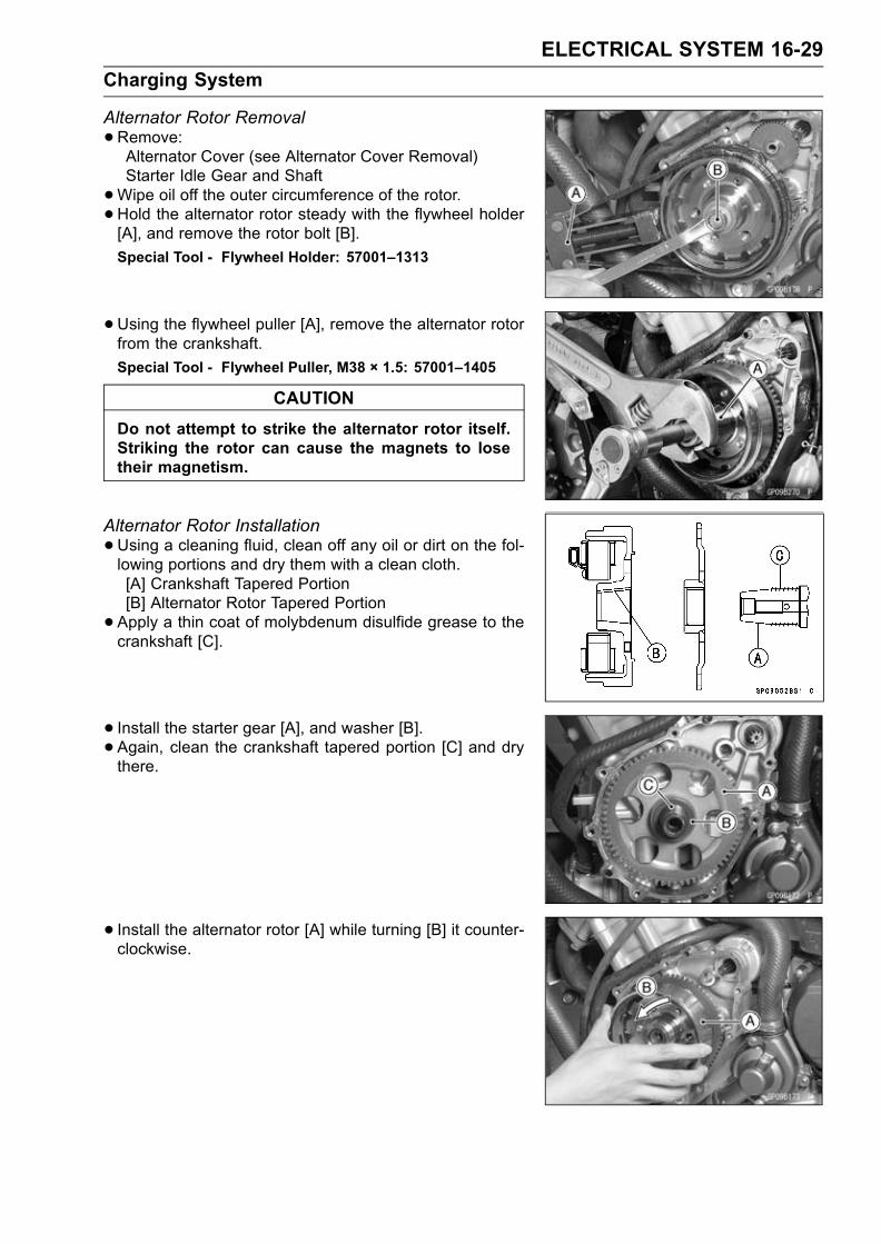
ELECTRICAL SYSTEM 16-29
Charging System
Alternator Rotor Removal
•Remove:Alternator Cover (see Alternator Cover Removal)Starter Idle Gear and Shaft
•Wipe oil off the outer circumference of the rotor.•Hold the alternator rotor steady with the flywheel holder[A], and remove the rotor bolt [B].
Special Tool - Flywheel Holder: 57001–1313
•Using the flywheel puller [A], remove the alternator rotorfrom the crankshaft.
Special Tool - Flywheel Puller, M38 × 1.5: 57001–1405
CAUTION
Do not attempt to strike the alternator rotor itself.Striking the rotor can cause the magnets to losetheir magnetism.
Alternator Rotor Installation
•Using a cleaning fluid, clean off any oil or dirt on the fol-lowing portions and dry them with a clean cloth.[A] Crankshaft Tapered Portion[B] Alternator Rotor Tapered Portion
•Apply a thin coat of molybdenum disulfide grease to thecrankshaft [C].
• Install the starter gear [A], and washer [B].• Again, clean the crankshaft tapered portion [C] and drythere.
• Install the alternator rotor [A] while turning [B] it counter-clockwise.
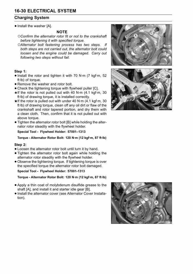
16-30 ELECTRICAL SYSTEM
Charging System
• Install the washer [A].NOTE
Confirm the alternator rotor fit or not to the crankshaftbefore tightening it with specified torque.Alternator bolt fastening process has two steps. Ifboth steps are not carried out, the alternator bolt couldloosen and the engine could be damaged. Carry outfollowing two steps without fail.
Step 1:
• Install the rotor and tighten it with 70 N·m (7 kgf·m, 52ft·lb) of torque.
•Remove the washer and rotor bolt.• Check the tightening torque with flywheel puller [C].If the rotor is not pulled out with 40 N·m (4.1 kgf·m, 30ft·lb) of drawing torque, it is installed correctly.If the rotor is pulled out with under 40 N·m (4.1 kgf·m, 30ft·lb) of drawing torque, clean off any oil dirt or flaw of thecrankshaft and rotor tapered portion, and dry them witha clean cloth. Then, confirm that it is not pulled out withabove torque.
• Tighten the alternator rotor bolt [B] while holding the alter-nator rotor steadily with the flywheel holder.
Special Tool - Flywheel Holder: 57001–1313
Torque - Alternator Rotor Bolt: 120 N·m (12 kgf·m, 87 ft·lb)
Step 2:
•Loosen the alternator rotor bolt until turn it by hand.• Tighten the alternator rotor bolt again while holding thealternator rotor steadily with the flywheel holder.
•Observe the tightening torque. If tightening torque is overthe specified torque the alternator rotor bolt damaged.
Special Tool - Flywheel Holder: 57001-1313
Torque - Alternator Rotor Bolt: 120 N·m (12 kgf·m, 87 ft·lb)
•Apply a thin coat of molybdenum disulfide grease to theshaft [A], and install it and starter idle gear [B].
• Install the alternator cover (see Alternator Cover Installa-tion).

ELECTRICAL SYSTEM 16-31
Charging System
Alternator InspectionThere are three types of alternator failures: short, open
(wire burned out), or loss in rotor magnetism. A short oropen in one of the coil wires will result in either a low output,or no output at all. A loss in rotor magnetism, which may becaused by dropping or hitting the alternator, by leaving itnear an electromagnetic field, or just by aging, will result inlow output.
• To check the alternator output voltage, do the followingprocedures.Turn off the ignition switch.Remove the fuel tank (see Fuel System chapter).Supply fuel to the throttle body with an auxiliary fuel tank.Disconnect the alternator lead connector [A].Connect the hand tester [B] as shown in the table 1.Start the engine, and run it 6 000 rpm 5 minutes.Run it at the rpm given in the table 1.Note the voltage readings (total 3 measurements).Table 1 Alternator Output Voltage
Tester Connections Reading
Range Tester (+) to Tester (–) to @ 4 000 rpm
250 V One Black Another 42.4 ∼AC lead Black lead 63.6 V

16-32 ELECTRICAL SYSTEM
Charging System
If the output voltage shows the value in the table, the al-ternator operates properly.If the output voltage shows a much higher than the valuein the table, the regulator/rectifier is damaged. A muchlower reading than that given in the table indicates thatthe alternator is defective.
•Check the stator coil resistance as follows.Stop the engine.Connect the commercially available tester as shown in thetable 2.Note the readings (total 3 measurement).Table 2 Stator Coil Resistance
Tester Connections Reading
Range Tester (+) to Tester (–) to
× 1 Ω One Black Another 0.3 ∼ 0.4 Ωlead Black lead
If there is more resistance than shown in the table, orno tester reading (infinity) for any two leads, the statorhas an open lead and must be replaced. Much less thanthis resistance means the stator is shorted, and must bereplaced.
•Using the highest resistance range of the hand tester,measure the resistance between each of the black leadsand chassis ground.Any hand tester reading less than infinity (∞) indicates ashort, necessitating stator replacement.If the stator coils have normal resistance, but the voltagecheck showed the alternator to be defective; then the rotormagnets have probably weakened, and the rotor must bereplaced.
Regulator/Rectifier Inspection
•Remove:Seat Cover (see Frame chapter)Fuel Tank (see fuel System chapter)Connectors [A] (disconnect)Clamp [B]
Bolts [A]Regulator/Rectifier [B]

ELECTRICAL SYSTEM 16-33
Charging System
Rectifier Circuit Check:
•Check the rectifier resistance as follows.•Disconnect the regulator/rectifier connector.•Connect the hand tester (special tool) to the regulator/rec-tifier as shown in the table, and check the resistance inboth directions of each diode in the rectifier following thetable.The resistance should be low in one direction and morethan ten times as much in the other direction. If any twoleads are low or high in both directions, the rectifier isdefective and the regulator/rectifier must be replaced.
NOTEThe actual meter reading varies with the meter usedand the individual rectifier, but, generally speaking thelower reading should be from zero to one half the scale.
No. Connections Reading Tester
Tester (+) Tester (-) Range
1 BK1
2 BK2 BK/BL ∞3 BK3
4 BK1
5 BK2 BK/W
6 BK3 x 10Ω7 BK1 1/2 scale or
8 BK/BL BK2 or less x 100Ω9 BK3
10 BK1
11 BK/W BK2 ∞12 BK3
Regulator Circuit Check:To test the regulator out of circuit, use three 12 V batteries
and a test light (12 V 3 ∼ 6 W bulb in a socket with leads).
CAUTION
The test light works as an indicator and also a cur-rent limiter to protect the regulator/rectifier from ex-cessive current. Do not use an ammeter instead ofa test light.

16-34 ELECTRICAL SYSTEM
Charging System
•Do the 1st step regulator circuit test.Connect the test light and the 12 V battery to the regula-tor/rectifier as shown.Check BK1, BK2, and BK3 terminal respectively.If the test light turns on, the regulator/rectifier is defective.Replace it.If the test light does not turn on, continue the test.
• Do the 2nd step regulator circuit test.Connect the test light and the 12 V battery in the samemanner as specified in the "1st step regulator circuit test".Apply 12 V to the BK/R terminal.Check BK1, BK2, and BK3 terminal respectively.If the test light turns on, the regulator/rectifier is defective.Replace it.If the test light does not turn on, continue the test.
• Do the 3rd step regulator circuit testConnect the test light and the 12 V battery in the samemanner as specified in the "1st step regulator circuit test".Momentarily apply 24 V to the BK/R terminal by adding a12 V battery.Check BK1, BK2, and BK3 terminals respectively.
CAUTION
Do not apply more than 24 volts. If more than 24volts is applied the regulator/rectifier may be dam-aged. Do not apply 24 V more than a few seconds.If 24 volts is applied for more than a few seconds,the regulator/rectifier may be damaged.
If the test light did not light when the 24 V was appliedmomentarily to the BK/R terminal, the regulator/rectifieris defective. Replace it.If the regulator/rectifier passes all of the tests described,it may still be defective. If the charging system still doesnot work properly after checking all of the componentsand the battery, test the regulator/rectifier by replacing itwith a known good unit.

ELECTRICAL SYSTEM 16-35
Charging System
Charging Voltage Inspection
•Check the battery condition (see Battery section).•Warm up the engine to obtain actual alternator operatingconditions.
•Remove the seats (see Frame chapter).• Check that the ignition switch is turned off, and connectthe hand tester [A] as shown in the table.
Special Tool - Hand Tester: 57001–1394
•Start the engine, and note the voltage readings at vari-ous engine speeds with the headlight turned on and thenturned off. (Disconnect the headlight connector in the up-per fairing.) The readings should show nearly battery volt-age when the engine speed is low, and, as the enginespeed rises, the readings should also rise. But they mustbe kept under the specified voltage.
Charging Voltage
Tester Connections Reading
Range Tester (+) to Tester (–) to
25 V DC Battery (+) Battery (–) 14.2 ∼ 15.2 V
• Turn off the ignition switch to stop the engine, and discon-nect the hand tester.If the charging voltage is kept between the values given inthe table, the charging system is considered to be workingnormally.If the charging voltage is much higher than the valuesspecified in the table, the regulator/rectifier is defectiveor the regulator/rectifier leads are loose or open.If the charging voltage does not rise as the engine speedincreases, then the regulator/rectifier is defective or thealternator output is insufficient for the loads. Check thealternator and regulator/rectifier to determine which partis defective.

16-36 ELECTRICAL SYSTEM
Charging System
Charging System Circuit
1. Ignition Switch2. Alternator
3. Regulator/Rectifier4. Battery
5. Main Fuse 30 A6. Load

ELECTRICAL SYSTEM 16-37
Ignition System

16-38 ELECTRICAL SYSTEM
Ignition System
WARNINGThe ignition system produces extremely high volt-age. Do not touch the spark plugs or stick coilswhile the engine is running, or you could receivea severe electrical shock.
CAUTION
Do not disconnect the battery leads or any otherelectrical connections when the ignition switch ison, or while the engine is running. This is to preventIC igniter damage.Do not install the battery backwards. The negativeside is grounded. This is to prevent damage to thediodes and IC igniter.
Crankshaft Sensor Removal
•Remove:Fuel Tank (see Fuel System chapter)Reserve TankRight Lower Fairing (see Frame chapter)Crankshaft Sensor Lead Connector [A]Side Stand Switch Lead Connector [B]
Neutral Switch Lead Connector [A]
Crankshaft Sensor CoverOil Pressure Switch Terminal [A]
•Remove the crankshaft sensor [B] by taking off the crank-shaft sensor bolts [C].
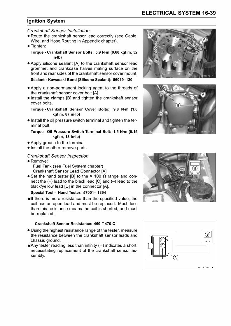
ELECTRICAL SYSTEM 16-39
Ignition System
Crankshaft Sensor Installation
•Route the crankshaft sensor lead correctly (see Cable,Wire, and Hose Routing in Appendix chapter).
• Tighten:Torque - Crankshaft Sensor Bolts: 5.9 N·m (0.60 kgf·m, 52
in·lb)
•Apply silicone sealant [A] to the crankshaft sensor leadgrommet and crankcase halves mating surface on thefront and rear sides of the crankshaft sensor cover mount.
Sealant - Kawasaki Bond (Silicone Sealant): 56019–120
•Apply a non-permanent locking agent to the threads ofthe crankshaft sensor cover bolt [A].
• Install the clamps [B] and tighten the crankshaft sensorcover bolts.
Torque - Crankshaft Sensor Cover Bolts: 9.8 N·m (1.0kgf·m, 87 in·lb)
• Install the oil pressure switch terminal and tighten the ter-minal bolt.
Torque - Oil Pressure Switch Terminal Bolt: 1.5 N·m (0.15kgf·m, 13 in·lb)
•Apply grease to the terminal.• Install the other remove parts.Crankshaft Sensor Inspection
•Remove:Fuel Tank (see Fuel System chapter)Crankshaft Sensor Lead Connector [A]
• Set the hand tester [B] to the × 100 Ω range and con-nect the (+) lead to the black lead [C] and (–) lead to theblack/yellow lead [D] in the connector [A].
Special Tool - Hand Tester: 57001– 1394
If there is more resistance than the specified value, thecoil has an open lead and must be replaced. Much lessthan this resistance means the coil is shorted, and mustbe replaced.
Crankshaft Sensor Resistance: 460 ∼ 470 Ω
•Using the highest resistance range of the tester, measurethe resistance between the crankshaft sensor leads andchassis ground.Any tester reading less than infinity (∞) indicates a short,necessitating replacement of the crankshaft sensor as-sembly.

16-40 ELECTRICAL SYSTEM
Ignition System
Crankshaft Sensor Peak Voltage
•Remove:Fuel Tank (see Fuel System chapter)Crankshaft Sensor Lead Connector
• Set the Hand Tester [B] to the × 10 V DC range, andconnect it a commercially available peak voltage adapter[E] as shown in the diagram.
•Connect the black lead (-) of the Adapter to black/yellowlead [D] and red lead (+) to black lead [C] in the crankshaftsensor connector [A].
• Turn the ignition switch and engine stop switch on.•Grasp the clutch lever and pushing the starter button, turnthe engine 4 ∼ 5 seconds with the transmission gear inneutral to measure the crankshaft sensor peak voltage.
•Repeat the measurement 5 or more times.Crankshaft Sensor Peak VoltageStandard: 2.0 V or more
Special Tool - Hand Tester: 57001–1394
Recommended Tool-
Peak Voltage Adapter
Type: KEK-54-9-B
Brand: KOWA SEIKI
Stick Coil (Ignition Coil together with Spark Plug Cap)Removal
•Remove the air cleaner housing (see Fuel System chap-ter).
• Disconnect the stick coil connectors [A].• Pull the stick coils [B] off the spark plugs.
CAUTION
Do not pry the connector part of the coil while re-moving the coil.
Stick Coil (Ignition Coil together with Spark Plug Cap)Installation
• Install the coil using the following steps.Insert the coil [A] as shown being careful of the coil instal-lation direction.Connect the connectors [B].Stick coil connectors angle [C]: about 45°
CAUTION
Do not tap the coil head while installing the coil.
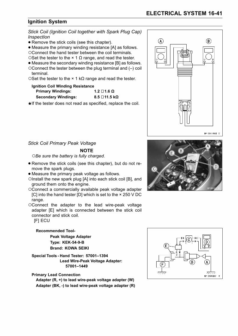
ELECTRICAL SYSTEM 16-41
Ignition System
Stick Coil (Ignition Coil together with Spark Plug Cap)Inspection
•Remove the stick coils (see this chapter).•Measure the primary winding resistance [A] as follows.Connect the hand tester between the coil terminals.Set the tester to the × 1 Ω range, and read the tester.•Measure the secondary winding resistance [B] as follows.Connect the tester between the plug terminal and (–) coilterminal.Set the tester to the × 1 kΩ range and read the tester.Ignition Coil Winding ResistancePrimary Windings: 1.2 ∼ 1.6 ΩSecondary Windings: 8.5 ∼ 11.5 kΩ
If the tester does not read as specified, replace the coil.
Stick Coil Primary Peak Voltage
NOTEBe sure the battery is fully charged.•Remove the stick coils (see this chapter), but do not re-move the spark plugs.
•Measure the primary peak voltage as follows.Install the new spark plug [A] into each stick coil [B], andground them onto the engine.Connect a commercially available peak voltage adapter[C] into the hand tester [D] which is set to the × 250 V DCrange.Connect the adapter to the lead wire-peak voltageadapter [E] which is connected between the stick coilconnector and stick coil.[F] ECU
Recommended Tool-
Peak Voltage Adapter
Type: KEK-54-9-B
Brand: KOWA SEIKI
Special Tools - Hand Tester: 57001–1394Lead Wire-Peak Voltage Adapter:57001–1449
Primary Lead ConnectionAdapter (R, +) to lead wire-peak voltage adapter (W)
Adapter (BK, -) to lead wire-peak voltage adapter (R)

16-42 ELECTRICAL SYSTEM
Ignition System
WARNINGTo avoid extremely high voltage shocks, do nottouch the spark plugs or tester connections.
•Turn the ignition switch and the engine stop switch ON.•Pushing the starter button, turn the engine 4 ∼ 5 secondswith the transmission in neutral to measure the primarypeak voltage.
•Repeat the measurements 5 times for one stick coil.Stick Coil Primary Peak VoltageStandard: 100 V or more
•Repeat the test for the other stick coil.If the reading is less than the specified value, check thefollowing.Stick Coils (see Stick Coil Inspection)Crankshaft Sensor (see Crankshaft Sensor Inspection)ECU (see Fuel System (DFI) chapter)
Spark Plug Removal
•Remove:Air Cleaner Housing (see Fuel System chapter)Stick Coils
•Remove the spark plugs using the 16 mm plug wrench.Owner’s Tool - Spark Plug Wrench, 16 mm: 92110–1146
Spark Plug Installation
• Insert the spark plug vertically into the plug hole with theplug [A] installed in the plug wrench [B].
Owner’s Tool - Spark Plug Wrench, 16 mm: 92110–1146
•Tighten:Torque - Spark Plugs: 13 N·m (1.3 kgf·m, 113 in·lb)
•Fit the stick coils securely.
Spark Plug Cleaning and InspectionRefer to the Electrical System in the Periodic Mainte-nance chapter.
Spark Plug Gap InspectionRefer to the Electrical System in the Periodic Mainte-nance chapter.

ELECTRICAL SYSTEM 16-43
Ignition System
Camshaft Position Sensor Removal
•Remove the lower fairings (see Frame chapter).• Lift the left side of the baffle plate and take out thecamshaft position sensor lead connector.
•Remove the left under side radiator bolt.•Move the bottom of the radiator toward the front [A], anddisconnect the camshaft position sensor lead connector[B].
• Remove:Camshaft Position Sensor Bolt [A]Camshaft Position Sensor [B]
Camshaft Position Sensor Installation
•Apply grease or engine oil to the O-ring on the camshaftposition sensor.
Tighten:
Torque - Camshaft Position Sensor Bolt: 12 N·m (1.2 kgf·m,106 in·lb)
Camshaft Position Sensor Inspection
•Remove:Right Lower Fairing (see Frame chapter)Camshaft Position Sensor Lead Connector (disconnect)
• Set the hand tester to the × 10 Ω range and connect it tothe terminals.
Special Tool - Hand Tester: 57001-1394
If there is more resistance than the specified value, thesensor coil has an open lead and must be replaced. Muchless than this resistance means the sensor coil is shorted,and must be replaced.
Camshaft Position Sensor Resistance: 490 ∼ 590 Ω
•Using the highest resistance range of the tester, mea-sure the resistance between the camshaft position sensorleads and chassis ground.Any tester reading less than infinity (∞) indicates a short,necessitating replacement of the camshaft position sen-sor.

16-44 ELECTRICAL SYSTEM
Ignition System
Camshaft Position Sensor Peak Voltage Inspection
•Remove:Right Lower Inner Cover (see Frame chapter)Camshaft Position Sensor Lead Connector
• Set the commercially available tester [A] to the 10 V DCrange.
•Connect commercially available peak voltage adapter [B]to the hand tester and camshaft position sensor leads inthe terminals.
Recommended Tool-
Peak Voltage Adapter
Type: KEK-54-9-B
Brand: KOWA SEIKI
Connections:Camshaft PositionSensor Terminal
Adapter Hand Tester
(+) [C] ← Red → (+)
(–) [D] ← Black → (–)
•Turn the ignition switch and engine stop switch on.• Pushing the starter button, turn the engine 4 ∼ 5 sec-onds with the transmission gear in neutral to measure thecamshaft position sensor peak voltage.
•Repeat the measurement 5 or more times.Camshaft Position Sensor Peak VoltageStandard: 0.1 V or more
If the peak voltage is lower than the standard, inspect thecamshaft position sensor.

ELECTRICAL SYSTEM 16-45
Ignition System
Interlock Operation Inspection
•Remove the seats (see Frame chapter).1st Check
•Measure the terminal voltage of the G/BK lead in the junc-tion box connector [A] in accordance with the followingprocedure.Set the tester [B] to the 25 V DC range, connect it to theG/BK lead and frame ground [C].
Connection:Tester (+) Terminal → G/BK Lead Terminal
Tester (–) Terminal → Frame Ground
Condition:Transmission Gear → 1st Position
Clutch Lever → Release
Side Stand → Down
Turn the ignition switch on.Read the voltage.Interlock Operation VoltageStandard: 4 V or more
If the voltage is lower than the standard, inspect the sidestand switch, starter lockout switch and junction box. Andtheir parts are normality, replace the ECU.If the voltage is standard, push the starter button to checkas follows.If the starter motor does not turn, the ECU is good, andcheck the starter system circuit.If the starter motor turned, ECU is defective. Replace theECU.

16-46 ELECTRICAL SYSTEM
Ignition System
2nd CheckRaise the rear wheel off the ground with a stand.
• Set the following conditions.Condition:Transmission Gear→ 1st Position
Clutch Lever → Release
Side Stand → Up
•Turn the ignition switch on and push the starter button.If turn the engine, inspect the starter lockout switch, sidestand switch and junction box.If their parts are normality, replace the ECU
•Set the following conditions.Condition:Transmission Gear→ 1st Position
Clutch Lever → Pull in
Side Stand → Up
•Turn the ignition switch on and push the starter button.If the engine dose not turn, inspect the starter lockoutswitch, side stand switch and junction box.If their parts are normality, replace the ECU.
• Inspect the engine for its secure stop after the followingoperations are completed.
•Run the engine to the following conditions.Condition:Transmission Gear→ 1st Position
Clutch Lever → Release
Side Stand → Up
•Set the side stand on the ground, then the engine willstop.If engine does not be stop, inspect the starter lockoutswitch, side stand switch and junction box.If their parts are normality, replace the ECU.
IC Igniter InspectionThe IC igniter is built in the ECU [A].•Refer to the Interlock Operation Inspection, Ignition Sys-tem Troubleshooting chart and Fuel System (DFI) chapterfor ECU Inspection.

ELECTRICAL SYSTEM 16-47
Ignition System
Ignition System Circuit
1. Junction Box2. Ignition Fuse 10A3. Ignition Switch4. Engine Stop Switch5. Starter Button6. Stick Coils7. Spark Plugs8. Subthrottle Motor9. Crankshaft Sensor10. Side Stand Switch
11. Camshaft Position Sensor12. Main Throttle Sensor13. Subthrottle Sensor14. Starter Lockout Switch15. ECU Main Relay16. ECU Fuse 15A17. Vehicle-down Sensor18. Battery19. Main Fuse 30A20. ECU (Electronic Control Unit)

16-48 ELECTRICAL SYSTEM
Electric Starter System
Starter Motor Removal
•Remove the fuel tank (see Fuel System (DFI) chapter).• Slide back the rubber cap.•Remove the starter motor terminal bolt [A] and the mount-ing bolts [B].
• Pull out the starter motor [C].
Starter Motor Installation
CAUTION
Do not tap the starter motor shaft or body. Tappingthe shaft or body could damage the motor.
•When installing the starter motor, clean the starter mo-tor legs [A] and crankcase [B] where the starter motor isgrounded.
•Replace the O-ring [A] with a new one.• Apply grease to the O-ring.• Tighten:Torque - Starter Motor Mounting Bolts: 9.8 N·m (1.0 kgf·m,
87 in·lb)
Starter Motor Disassembly
•Take off the starter motor through bolts [A] and removeboth end covers [B] and pull the armature out of the yoke[C].
Starter Motor Assembly
•Apply a thin coat of grease to the oil seal [A].• Fit the toothed washer [B] into the left-hand end cover.• Install the washer [C].
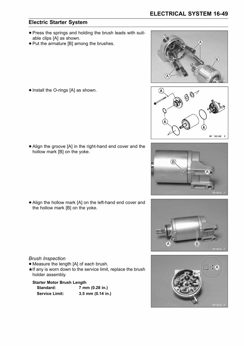
ELECTRICAL SYSTEM 16-49
Electric Starter System
•Press the springs and holding the brush leads with suit-able clips [A] as shown.
• Put the armature [B] among the brushes.
• Install the O-rings [A] as shown.
• Align the groove [A] in the right-hand end cover and thehollow mark [B] on the yoke.
• Align the hollow mark [A] on the left-hand end cover andthe hollow mark [B] on the yoke.
Brush Inspection
•Measure the length [A] of each brush.If any is worn down to the service limit, replace the brushholder assembly.
Starter Motor Brush LengthStandard: 7 mm (0.28 in.)
Service Limit: 3.5 mm (0.14 in.)

16-50 ELECTRICAL SYSTEM
Electric Starter System
Commutator Cleaning and Inspection
•Smooth the commutator surface [A] if necessary with fineemery cloth [B], and clean out the grooves.
•Measure the diameter [A] of the commutator [B].If the commutator diameter is less than the service limit,replace the starter motor with a new one .
Commutator DiameterStandard: 24 mm (0.94 in.)
Service Limit: 23 mm (0.91 in.)
Armature Inspection
•Using the × 1 Ω hand tester range, measure the resis-tance between any two commutator segments [A].
Special Tool - Hand Tester: 57001–1394
If there is a high resistance or no reading (∞) between anytwo segments, a winding is open and the starter motormust be replaced.
•Using the highest hand tester range, measure the resis-tance between the segments and the shaft [B].If there is any reading at all, the armature has a short andthe starter motor must be replaced.
NOTEEven if the foregoing checks show the armature to begood, it may be defective in some manner not readilydetectable with the hand tester. If all other starter motorand starter motor circuit components check good, butthe starter motor still does not turn over or only turnsover weakly, replace the starter motor with a new one.
Brush Lead Inspection
•Using the × 1 Ω hand tester range, measure the resis-tance as shown.[A] Terminal Bolt and Positive Brush[B] Right–hand End Cover and Negative Brush
Special Tool - Hand Tester: 57001–1394
If there is not close to zero ohms, the brush lead has anopen. Replace the positive brush assembly and/or thenegative brush subassembly.

ELECTRICAL SYSTEM 16-51
Electric Starter System
Right–hand End Cover Assembly Inspection
•Using the highest hand tester range, measure the resis-tance as shown.[A] Terminal and Right–hand End Cover
Special Tool - Hand Tester: 57001–1394
If there is any reading, the right-hand end cover assemblyhave a short. Replace the right-hand end cover assembly.
Starter Relay Inspection
•Remove:Seats (see Frame chapter)Starter Cable [A]Battery Cable [B]Connector [C]Starter Relay [D]
•Connect the hand tester [A] and 12 V battery [B] to thestarter relay [C] as shown.
Special Tool - Hand Tester: 57001–1394
If the relay does not work as specified, the relay is defec-tive. Replace the relay.
Testing RelayTester Range: × 1 Ω range
Criteria: When battery is connected→ 0 ΩWhen battery is disconnected→ ∞ Ω

16-52 ELECTRICAL SYSTEM
Electric Starter System
Electric Starter Circuit
1. Ignition Switch2. Engine Stop Switch3. Starter Button4. Junction Box5. Starter Circuit Relay
6. Ignition Fuse 10A7. Side Stand Switch8. Neutral Switch9. Starter Lockout Switch10. Starter Motor
11. Diode12. Starter Relay13. Main Fuse 30 A14. Battery

ELECTRICAL SYSTEM 16-53
Lighting System
This motorcycle adopt the daylight system and have aheadlight relay in the junction box. The headlight does notgo on when the ignition switch and the engine stop switchare first turned on. The headlight comes on after the starterbutton is released and stays on until the ignition switch isturned off. The headlight will go out momentarily wheneverthe starter button is pressed and come back on when thebutton is released.
Headlight Beam Horizontal Vertical Adjustment
•Remove the inner (upper) fairing (see Frame chapter).• Turn the horizontal adjuster [A] on the headlight in or outuntil the beam points straight ahead.
• Turn the vertical adjusters [B] on the headlight in or out toadjust the headlight vertically.
NOTEOn high beam, the brightest points should be slightlybelow horizontal with the motorcycle on its wheels andthe rider seated. Adjust the headlight(s) to the properangle according to local regulations.For US model, the proper angle is 0.4 degrees belowhorizontal. This is 50 mm (2 in.) drop at 7.6 m (25ft) measured from the center of the headlights with themotorcycle on its wheels and the rider seated.
50 mm (2 in.) [A]Center of Brightest Spot [B]7.6 m (25 ft) [C]Height of Headlight Center [D]Low Beam [E]High Beam [F]

16-54 ELECTRICAL SYSTEM
Lighting System
Headlight Bulb Replacement
•Remove:Headlight Bulb Dust CoverHeadlight Connector [A]Hook [B]Headlight Bulb [C]
CAUTION
When handling the quartz–halogen bulb, nevertouch the glass portion with bare hands. Alwaysuse a clean cloth. Oil contamination from hands ordirty rags can reduce bulb life or cause the bulb toexplode.
NOTEClean off any contamination that inadvertently gets onthe bulb with alcohol or soap and water solution.
•Replace the headlight bulb.• Align the mark [A] on the headlight and mark [B] the dustcover, and turn the dust cover clockwise so that the mark[B] faces topward.
• After installation, adjust the headlight aim (see this chap-ter).
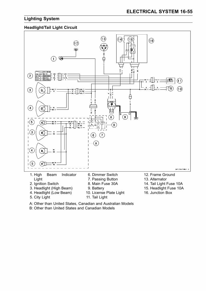
ELECTRICAL SYSTEM 16-55
Lighting System
Headlight/Tail Light Circuit
1. High Beam IndicatorLight
2. Ignition Switch3. Headlight (High Beam)4. Headlight (Low Beam)5. City Light
6. Dimmer Switch7. Passing Button8. Main Fuse 30A9. Battery10. License Plate Light11. Tail Light
12. Frame Ground13. Alternator14. Tail Light Fuse 10A15. Headlight Fuse 10A16. Junction Box
A: Other than United States, Canadian and Australian ModelsB: Other than United States and Canadian Models

16-56 ELECTRICAL SYSTEM
Lighting System
Turn Signal Relay Inspection
•Remove:Seats (see Frame chapter)Turn Signal Relay [A]
•Connect one 12 V battery and turn signal lights as indi-cated in the figure, and count how may times the lightsflash for one minute.Turn Signal Relay [A]Turn Signal Lights [B]12 V Battery [C]If the lights do not flash as specified, replace the turn sig-nal relay.
Testing Turn Signal Relay
Load
The Number
of Turn Wattage (W) Flashing times
Signal Lights (c/m*)
1** 21 140 - 250
2 42 75 – 95
(*): Cycle(s) per minute(**): Correspond to “one light burned out”

ELECTRICAL SYSTEM 16-57
Lighting System
Turn Signal Light Circuit
1. Turn Signal Indicator Lights(Right & Left)
2. Front Right Turn Signal Light3. Front Left Turn Signal Light4. Turn Signal Switch5. Turn Signal Relay6. Junction Box
7. Turn Signal Relay Fuse 10A8. Ignition Switch9. Rear Right Turn Signal Light10. Rear Left Turn Signal Light11. Main Fuse 30 A12. Battery
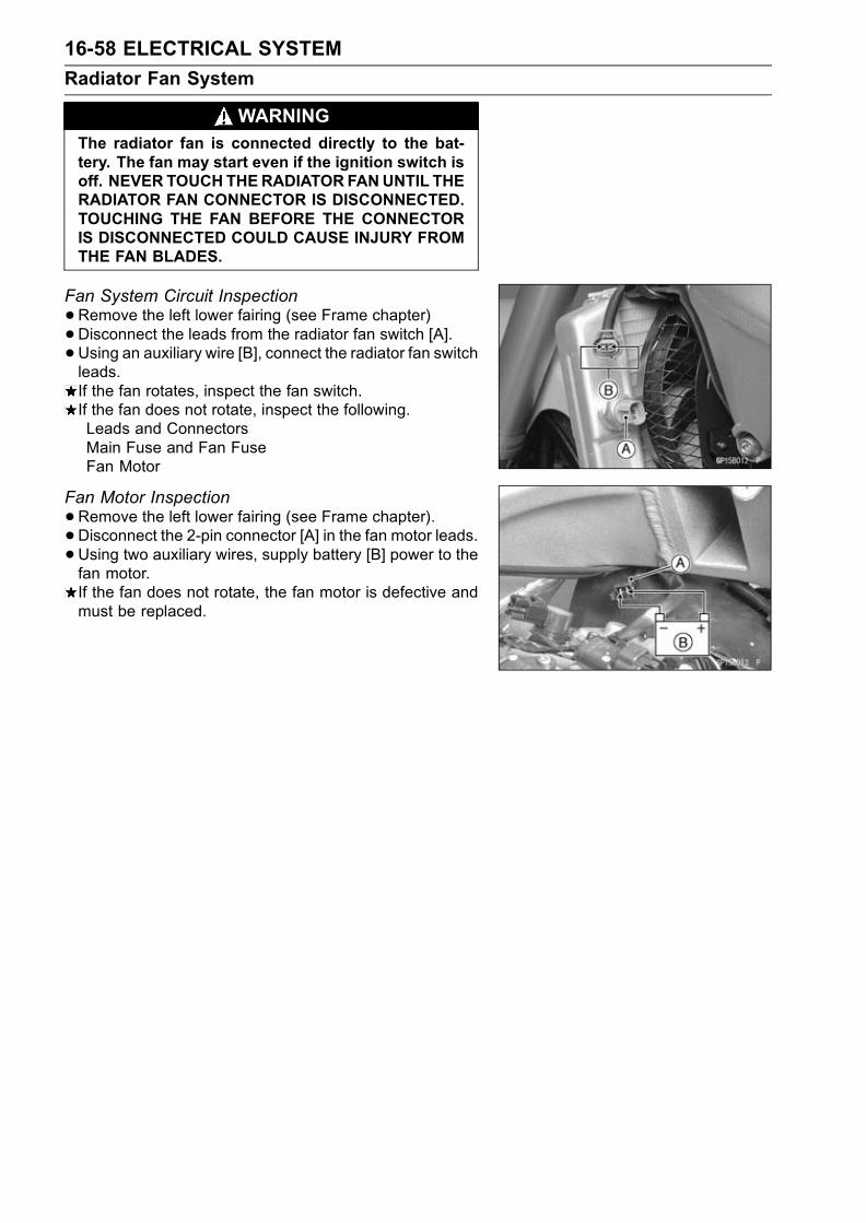
16-58 ELECTRICAL SYSTEM
Radiator Fan System
WARNINGThe radiator fan is connected directly to the bat-tery. The fan may start even if the ignition switch isoff. NEVER TOUCH THERADIATOR FANUNTIL THERADIATOR FAN CONNECTOR IS DISCONNECTED.TOUCHING THE FAN BEFORE THE CONNECTORIS DISCONNECTED COULD CAUSE INJURY FROMTHE FAN BLADES.
Fan System Circuit Inspection
•Remove the left lower fairing (see Frame chapter)•Disconnect the leads from the radiator fan switch [A].
•Using an auxiliary wire [B], connect the radiator fan switchleads.If the fan rotates, inspect the fan switch.If the fan does not rotate, inspect the following.Leads and ConnectorsMain Fuse and Fan FuseFan Motor
Fan Motor Inspection
•Remove the left lower fairing (see Frame chapter).• Disconnect the 2-pin connector [A] in the fan motor leads.•Using two auxiliary wires, supply battery [B] power to thefan motor.If the fan does not rotate, the fan motor is defective andmust be replaced.
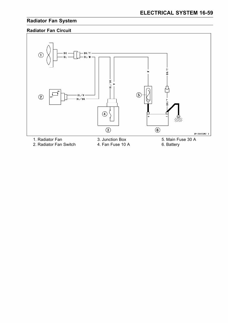
ELECTRICAL SYSTEM 16-59
Radiator Fan System
Radiator Fan Circuit
1. Radiator Fan2. Radiator Fan Switch
3. Junction Box4. Fan Fuse 10 A
5. Main Fuse 30 A6. Battery
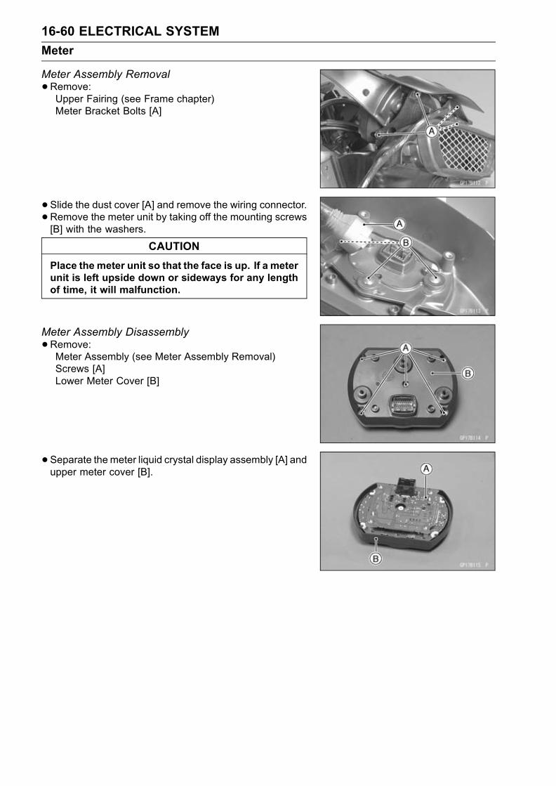
16-60 ELECTRICAL SYSTEM
Meter
Meter Assembly Removal
•Remove:Upper Fairing (see Frame chapter)Meter Bracket Bolts [A]
• Slide the dust cover [A] and remove the wiring connector.•Remove the meter unit by taking off the mounting screws[B] with the washers.
CAUTION
Place the meter unit so that the face is up. If a meterunit is left upside down or sideways for any lengthof time, it will malfunction.
Meter Assembly Disassembly
•Remove:Meter Assembly (see Meter Assembly Removal)Screws [A]Lower Meter Cover [B]
• Separate the meter liquid crystal display assembly [A] andupper meter cover [B].

ELECTRICAL SYSTEM 16-61
Meter, Gauge, Indicator Unit
Electronic Combination Meter Assembly Inspection
•Remove the meter assembly [A].[1] Ignition [10] Battery (+)
[2] Fuel Reserve Switch [11] Oil Pressure Warning
[3] Stop Watch (+) Indicator Light (LED)
[4] Lap Time (+) Ground (–)
[5] Neutral Indicator Light [12] Speed Sensor Supply
(LED) Ground (–) Voltage
[6] FI Indicator Light [13] Right Turn Signal Light
(LED) Ground (–) (LED) (+)
[7] Tachometer Pulse [14] Left Turn Signal Indicator
[8] Water Temperature Light (LED) (+)
Sensor [15] High Beam Indicator Light
[9] Ground (–) (LED)
[16] Speed Sensor Pulse
CAUTION
Do not drop the meter unit. Place the meter unit sothat it faces upward. If themeter assembly is left up-side down or sideways for a long time or dropped,it will malfunction.
CAUTION
Do not short each terminals.
Liquid Crystal Display (LCD) Segments Check:
•Connect the harness adapter to the meter assembly con-nector.
Special Tool - Harness Adapter: 57001–1542
•Using the auxiliary wires, connect the 12 V battery to theeach connector of harness adapter as follows.Connect the battery positive terminal to the terminal [10].Connect the battery negative terminal to the terminal [9].
• Connect the terminal [1] to the terminal [10].

16-62 ELECTRICAL SYSTEM
Meter, Gauge, Indicator Unit
The tachometer LCD segments momentarily to it lastreadings two times and segment movement is reversal.When the terminals are connected, all the LCD segments[A] and LED warning light [B] appear for three seconds.If the LCD segments and LED warning light will not ap-pear, replace the meter assembly.
•Disconnect the terminal [1].All the LCD segments and LED warning light disappear.If the segments do not disappear, replace the meter as-sembly.
MODE AND RESET BUTTON Operation Check:
•Connect the 12 V battery and terminals in the same man-ner as specified in the "Liquid Crystal Display (LCD) Seg-ments Check".
•Check that the display [B] change to the ODO, TRIP, andCLOCK and STOP WATCH displays each time the modeselector button [A] is pressed.If the display function does not work, replace the meterassembly.
• Indicate the clock mode.•Check that when the RESET button in CLOCK mode ispushed for more than two seconds, the meter displayturns to the clock set mode.Both the hour and minute display start flashing.
• In the HOUR/MINUTE setting mode, press the reset but-ton [C] again to effect the HOUR setting mode.The hour display flashes on the display.• Press the mode selector button [A] to set the hour.

ELECTRICAL SYSTEM 16-63
Meter, Gauge, Indicator Unit
• In the HOUR setting mode, press the reset button [C] toeffect the MINUTE setting mode.The minute display flashes on the display.• Press the mode selector button [A] to set the minute.
• In the MINUTE setting mode, press the reset button [C]to return to the HOUR/MINUTE setting mode.
• Press the mode selector button [A] to complete the timesetting process.The clock starts counting the seconds a soon as themodeselector button is pressed.
• Indicate the ODO mode.If the display function does not work and adjust, replacethe meter assembly.Check that the display [A] [B] change to the mile and °F,Mile and °C, km and °F, km and °C display each time bypushing the RESET bottom while MODE bottom pushedin.
NOTEMile/Km Display can alternate between English andmetric modes (mile and km) in the digital meter. Makesure that km or mile according to local regulations iscorrectly displayed before riding.
Speedometer Check:
•Connect the 12 V battery and terminals in the same man-ner as specified in the "Liquid Crystal Display (LCD) Seg-ments Check".
• The speed equivalent to the input frequency is indicated inthe oscillator [A], if the square wave (illustrated as shown)would be input into the terminal [16].Indicates approximately 60 mph in case the input fre-quency would be approximately 146 Hz.Indicates approximately 60 km/h in case the input fre-quency would be approximately 91 Hz.
• If the oscillator is not available, the speedometer can bechecked as follows.Install the meter unit.Raise the rear wheel off the ground, using the jack.Turn on the ignition switch.Rotate the rear wheel by hand.Check that the speedometer shows the speed.If the speedometer does not work, check the speed sen-sor electric source voltage and speed sensor.The electric source voltage and speed sensor are normal,replace the meter assembly.

16-64 ELECTRICAL SYSTEM
Meter, Gauge, Indicator Unit
Speed Sensor Electric Source Check:
•Connect the 12 V battery and terminals in the same man-ner as specified in the "Liquid Crystal Display (LCD) Seg-ments Check".
• Set the hand tester to the DC25 V range and connect it tothe terminals [12] and [9].If the voltage is less than 8 V, replace the meter assembly.
Odometer Check:
•Check the odometer with the speedometer check in thesame way.If value indicated in the odometer is not added, replacethe meter assembly.
NOTEThe data is maintained even if the battery is discon-nected.When the figures come to 999999, they are stopped andlocked.
Trip Meter Check:
•Check the trip meter with the speedometer in the sameway.If value indicated in the trip meter is not added, replacethe meter assembly.
•Check that when the RESET button is pushed for morethan two seconds, the figure display turns to 0.0.If the figure display does not indicate 0.0, replace the me-ter assembly.
Water Temperature Meter Check:
•Connect the 12 V battery and terminals in the same man-ner as specified in the "Liquid Crystal Display (LCD) Seg-ments Check".
•Connect the variable rheostat [A] to the terminal [8] asshown.
•Check that the number of segments matches the resis-tance value of the variable rheostat.
Resistance Temperature Warning
Value (Ω) Meter Indicate
– [A] –
209.8 50°C (122°F) [B] –
69.1 80°C (176°F) [B] –
21.2 120°C (248°F) [C] Flash
17 HI [D] Flash
• If any display function does not work, replace the meterassembly.

ELECTRICAL SYSTEM 16-65
Meter, Gauge, Indicator Unit
Tachometer Check:
•Connect the 12 V battery and terminals in the same man-ner as specified in the "Liquid Crystal Display (LCD) Seg-ments Check".
• The revolutions per minute (rpm) equivalent to the inputfrequency is indicated in the oscillator [A] if the squarewave (illustrated as shown) would be input into the termi-nal [7].Indicates approximately 6500 rpm in case the input fre-quency would be approximately 200 Hz.
• If the oscillator is not available, the tachometer can bechecked as follows.Connect the 12 V battery and terminals in the same man-ner as specified in the "Liquid Crystal Display (LCD) Seg-ments Check".Using an auxiliary wire, quickly open and connect the ter-minal [1] to the terminal [7] repeatedly.
Then the tachometer segment [A] should flick [B].If the hand does not flick, replace the meter assembly.

16-66 ELECTRICAL SYSTEM
Meter, Gauge, Indicator Unit
Stop Watch Check:
•Connect the 12V battery and terminal in the same man-ner as specified in the “Liquid Crystal Display (LCD) Seg-ments Check”.
• Press the mode selector button each time to set the stopwatch mode.
•Connect the auxiliary wire to the terminal [3] as shown,then stop watch start to count.
•While count the stop watch, connect the auxiliary wire tothe terminal [4] as shown, then indicate the counted timeduring ten seconds.
•Connect the variable rheostat [A] to the terminal [8] asshown.
•When Set the resistance to less than 21.1Ω, lap displaysegment indicate the water temperature.If the display function does not work, replace the materassembly.
LED Lights Inspection:
•Connect the 12 V battery and terminals in the same man-ner as specified in the “Liquid Crystal Display (LCD) Seg-ments check.”Neutral Indicator Light (LED) [A]FI Indicator Light (LED) [B]Oil Pressure Warning Indicator Light (LED) [C]Turn Signal Indicator Light (LED) [D]High Beam Indicator Light (LED) [E]Fuel Level Warning Indicator Light (LED) [F]Shift Up Indicator Light (LED) [G]
•Using the auxiliary leads and harness adapter, connect a12 V battery to the meter unit connector as follows.
Special Tool - Harness Adapter: 57001–1542
Neutral Indicator Light (LED):Battery Negative (–) Terminal To Terminal [5]

ELECTRICAL SYSTEM 16-67
Meter, Gauge, Indicator Unit
FI Indicator Light (LED):Battery Negative (–) Terminal To Terminal [6]
Oil Pressure Warning Indicator Light (LED):Battery Negative (–) Terminal To Terminal [11]
Right and Left Turn Signal Indicator Light (LED):Battery Positive (+) Terminal to Terminal [13]Battery Positive (+) Terminal to Terminal [14]
High Beam Indicator Light (LED):Battery Positive (+) Terminal to Terminal [15]
Fuel Level Warning Indicator Light (LED):
•Connect a variable rheostat [C] to terminal [2] and [9] asshown.
• Adjust the resistance value to the approximately 22 Ω.

16-68 ELECTRICAL SYSTEM
Meter, Gauge, Indicator Unit
Shift Up Indicator Light (LED):
•Connect the 12V battery and terminal in the same man-ner as specified in the “Liquid Crystal Display (LCD) Seg-ments Check”.
• The revolutions per minute(rpm)equivalent to the inputfrequency is indicated in the oscillator [A] if the squarewave(illustrated as shown) would be input into the termi-nal [7].
•When set the oscillator more than 440Hz, shift up indica-tor light(LED) go on.
If each LED lights does not go on, replace the meter as-sembly.
Meter Circuit
1. Turn Signal Indicator Light (LED)2. High Beam Indicator Light (LED)3. Neutral Indicator Light (LED)4. Oil Pressure Warning Indicator Light (LED)5. Fuel Level Warning Indicator Light (LED)6. FI Indicator Light (LED)7. Odometer/Trip Meter/Clock/Stop Watch Indicator
8. Water TemperatureGauge
9. Tachometer10. Speedometer11. Meter Light (LED)12. Shift Up Indicator Light (LED)13. Meter Assembly
14. Frame Ground15. Stop Watch Switch16. Speed Sensor17. Fuel Reserve Switch18. Water Temperature Sensor19. Oil Pressure Switch20. Neutral Switch21. Ignition Switch22. Lap Switch23. Junction Box24. ACC Fuse 10A25. Ignition Fuse 10A26. Main Fuse 30A27. Battery 12 V 8 Ah28. E.C.U.

ELECTRICAL SYSTEM 16-69
Switches and Sensors
Brake Light Timing InspectionRefer to the Brakes in the Periodic Maintenance chapter.Brake Light Timing AdjustmentRefer to the Brakes in the Periodic Maintenance chapter.Switch Inspection
•Using a hand tester, check to see that only the con-nections shown in the table have continuity (about zeroohms).For the handlebar switches and the ignition switch, referto the tables in the Wiring Diagram.If the switch has an open or short, repair it or replace itwith a new one.
Special Tool - Hand Tester: 57001–1394
Rear Brake Light Switch Connections
Side Stand Switch Connections
Neutral Switch Connections
Oil Pressure Switch Connections*
*: Engine lubrication system is in good condition

16-70 ELECTRICAL SYSTEM
Switches and Sensors
Radiator Fan Switch Inspection
•Remove the fan switch (see Cooling System chapter).• Suspend the switch [A] in a container of coolant so thatthe temperature-sensing projection and threaded portionare submerged.
• Suspend an accurate thermometer [B] in the coolant.NOTE
The switch and thermometer must not touch the con-tainer sides or bottom.
•Place the container over a source of heat and gradu-ally raise the temperature of the coolant while stirring thecoolant gently.
•Using the hand tester, measure the internal resistanceof the switch across the terminals at the temperaturesshown in the table.If the hand tester does not show the specified values, re-place the switch.
Fan Switch ResistanceRising temperature:
From OFF to ON at 93 ∼ 103°C (199 ∼ 217°F)Falling temperature:
Fan stops with the temperature 3 ∼ 8°C (38 ∼ 46°F)lower than the operation temperature range.
ON: Less than 0.5 ΩOFF: More than 10 MΩ

ELECTRICAL SYSTEM 16-71
Switches and Sensors
Water Temperature Sensor Inspection
•Remove the water temperature sensor (see Fuel System(DFI) chapter).
• Suspend the sensor [A] in a container of coolant so thatthe temperature-sensing projection [E] and threaded por-tion [E] are submerged.
• Suspend an accurate thermometer [B] in the coolant.NOTE
The sensor and thermometer must not touch the con-tainer side or bottom.
•Place the container over a source of heat and gradu-ally raise the temperature of the coolant while stirring thecoolant gently.
•Using the hand tester, measure the internal resistance ofthe sensor.The sensor sends electric signals to the ECU (ElectronicControl Unit) and coolant temperature gauge in the meterunit.Measure the resistance across the terminals and the body(for the gauge) at the temperatures shown in the table.If the hand tester does not show the specified values, re-place the sensor.
Water Temperature Sensor
Resistance for ECU [C]
Resistance (kΩ)Temperature
(Terminal [1] - [3])
+ 0.11520°C (68°F) 2.46
– 0.143
80°C (176°F) 0.32 ± 0.011
110°C (230°F) 0.1426 ± 0.0041
Resistance for Water Temperature Gauge [D]
Resistance (Ω)Temperature
(Terminal [2] - Body)
50°C (122°F) 210 ± 40
120°C (248°F) 21.2 ± 1.5
Speed Sensor Removal
•Remove:Fuel Tank (see Fuel system (DFI) chapter)Reserve Tank [A]Speed Sensor Bolt [B]
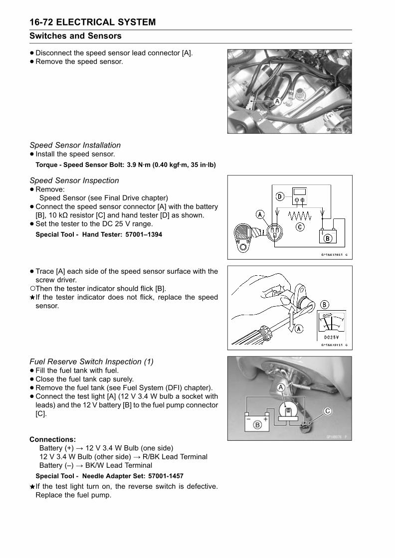
16-72 ELECTRICAL SYSTEM
Switches and Sensors
•Disconnect the speed sensor lead connector [A].• Remove the speed sensor.
Speed Sensor Installation
• Install the speed sensor.Torque - Speed Sensor Bolt: 3.9 N·m (0.40 kgf·m, 35 in·lb)
Speed Sensor Inspection
•Remove:Speed Sensor (see Final Drive chapter)
•Connect the speed sensor connector [A] with the battery[B], 10 kΩ resistor [C] and hand tester [D] as shown.• Set the tester to the DC 25 V range.Special Tool - Hand Tester: 57001–1394
•Trace [A] each side of the speed sensor surface with thescrew driver.Then the tester indicator should flick [B].If the tester indicator does not flick, replace the speedsensor.
Fuel Reserve Switch Inspection (1)
•Fill the fuel tank with fuel.• Close the fuel tank cap surely.•Remove the fuel tank (see Fuel System (DFI) chapter).• Connect the test light [A] (12 V 3.4 W bulb a socket withleads) and the 12 V battery [B] to the fuel pump connector[C].
Connections:Battery (+)→ 12 V 3.4 W Bulb (one side)12 V 3.4 W Bulb (other side)→ R/BK Lead TerminalBattery (–) → BK/W Lead Terminal
Special Tool - Needle Adapter Set: 57001-1457
If the test light turn on, the reverse switch is defective.Replace the fuel pump.
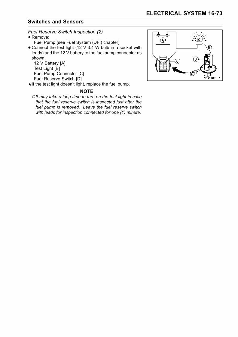
ELECTRICAL SYSTEM 16-73
Switches and Sensors
Fuel Reserve Switch Inspection (2)
•Remove:Fuel Pump (see Fuel System (DFI) chapter)
•Connect the test light (12 V 3.4 W bulb in a socket withleads) and the 12 V battery to the fuel pump connector asshown.12 V Battery [A]Test Light [B]Fuel Pump Connector [C]Fuel Reserve Switch [D]If the test light doesn’t light, replace the fuel pump.
NOTEIt may take a long time to turn on the test light in casethat the fuel reserve switch is inspected just after thefuel pump is removed. Leave the fuel reserve switchwith leads for inspection connected for one (1) minute.

16-74 ELECTRICAL SYSTEM
Junction Box
The junction box [A] has fuses [B], relays, and diodes.The relays and diodes can not be removed.
Junction Box Fuse Circuit Inspection
•Remove the seats (see Frame chapter).• Remove the junction box.• Pull off the connectors from the junction box.
•Make sure all connector terminals are clean and tight, andnone of them have been bent.Clean the dirty terminals, and straighten slightly–bent ter-minals.
•Check conductivity of the numbered terminals with thehand tester.If the tester does not read as specified, replace the junc-tion box.
Special Tool - Hand Tester: 57001–1394
Fuse Circuit Inspection
Tester Connection Tester Reading (Ω) Tester Connection Tester Reading (Ω)1 - 1A 0 1A - 8 ∞1 - 2 0 2 - 8 ∞3A - 4 0 3A - 8 ∞6 - 5 0 6 - 2 ∞6 - 10 0 6 - 3A ∞6 - 7 0 17 - 3A ∞6 - 17 0
Starter Circuit/Headlight Relay Inspection
•Remove the junction box.•Check conductivity of the following numbered terminalsby connecting the hand tester and one 12 V battery to thejunction box as shown.If the tester does not read as specified, replace the junc-tion box.
Special Tool - Hand Tester: 57001–1394

ELECTRICAL SYSTEM 16-75
Junction Box
Relay Circuit Inspection (with the battery disconnected)
TesterConnection
Tester Reading(Ω)
TesterConnection
Tester Reading (Ω)
7 - 8 ∞ 9 - 11 ∞Headlight 7 - 13 ∞ Starter Circuit 12 - 13 ∞Relay (+) (-) Relay (+) (-)
13 - 9 Not ∞ * 13 - 11 ∞(+) (-)
12 - 11 Not ∞ *
(*): The actual reading varies with the hand tester used.(+): Apply tester positive lead.(–): Apply tester negative lead.
Relay Circuit Inspection (with the battery connected)
Battery Tester Tester
Connection Connection Reading
(+) (–) (Ω)Headlight Relay 9 – 13 7 – 8 0
(+) (–)
Starter Circuit Relay 11 – 12 13 – 11 Not ∞ *
(*): The actual reading varies with the hand tester used.(+): Apply tester positive lead.(–): Apply tester negative lead.
Diode Circuit Inspection
•Remove the junction box.•Check conductivity of the following pairs of terminals.Diode Circuit Inspection
Tester Connection13–8, 13–9, 12–11, 12–14,
15–14, 16–14
The resistance should be low in one direction and morethan ten times as much in the other direction. If any diodeshows low or high in both directions, the diode is defectiveand the junction box must be replaced.
NOTEThe actual meter reading varies with the meter usedand the individual diodes, but, generally speaking, thelower reading should be from zero to one half the scale.

16-76 ELECTRICAL SYSTEM
Junction Box
Junction Box Internal Circuit
A. Accessory Fuse 10 AB. Fan Fuse 10 AC. Turn Signal Relay Fuse 10 AD. Horn Fuse 10 AE. Ignition Fuse 10 AF. Headlight Fuse 10 A
G. Headlight RelayH. Headlight DiodesI. Starter DiodeJ. Starter Circuit RelayK. Interlock DiodesL. Taillight Fuse 10 A

ELECTRICAL SYSTEM 16-77
Fuse
30 A Main Fuse Removal
•Remove:Seats (see Frame chapter)Starter Relay and 30 A Main Fuse Connector [A]
• Pull out the main fuse [B] from the starter relay with needlenose pliers.
Junction Box Fuse Removal
•Remove the seats (see Frame chapter).• Unlock the hook to lift up the lid [A].• Pull the fuses [B] straight out of the junction box with nee-dle nose pliers.
15A ECU Fuse Removal
•Remove:Seats (see Frame chapter)15A ECU Fuse [A]
Fuse Installation
• If a fuse fails during operation, inspect the electrical sys-tem to determine the cause, and then replace it with anew fuse of proper amperage.
• Install the junction box fuses on the original position asspecified on the lid.
Fuse Inspection
•Remove the fuse (see Fuse Removal).• Inspect the fuse element.If it is blown out, replace the fuse. Before replacing ablown fuse, always check the amperage in the affectedcircuit. If the amperage is equal to or greater than thefuse rating, check the wiring and related components fora short circuit.
Housing [A] Terminals [C]
Fuse Element [B] Blown Element [D]
CAUTION
When replacing a fuse, be sure the new fusematches the specified fuse rating for that circuit.Installation of a fuse with a higher rating may causedamage to wiring and components.


APPENDIX 17-1
17
Appendix
Table of Contents
Cable, Wire, and Hose Routing .............................................................................................. 17-2Troubleshooting Guide ........................................................................................................... 17-12

17-2 APPENDIX
Cable, Wire, and Hose Routing
1. Clucth Cable2. Choke Cable3. Throttle Cables4. Coolant Reserve Tank Hose5. Coolant By-pass Hose6. Main Harness7. Turn Signal Light Lead8. Left Handlebar Switch Lead9. Right Handlebar Switch Lead10. Run the starter cable under the throttle
cables and clutch cable.11. Run the clutch cable and through the
clamp.
12. Clamp the throttle cables and clutch cableand run the clutch cable above the throttlecables.
13. Run the clutch cable above the coolanthose and through the main harness in-side.
14. Run the meter lead forward the bracket.15. Clamp the meter lead.16. Run the left handlebar switch lead under
the main harness.17. Clamp the left handlebar switch lead.18. Clamp the headlight lead and the left han-
dlebar switch lead.

APPENDIX 17-3
Cable, Wire, and Hose Routing
1. Seat Lock Cable2. ECU (Electrical Control Unit)3. ECU Fuse15A4. Turn Signal Relay5. Fuel Pump Relay6. ECU Main Relay7. Battery (+) Lead8. Battery9. Vehicle-down Sensor10. Frame Ground11. Clamp12. Self-diagnosis Terminal13. Battery (-) Lead14. Junction Box15. Clamp16. Starter Relay and Main Fuse30A17. Turn Signal Light Lead Connector(Left and Right), License Light Lead Connector and Tail/Brake
Light(LED) Lead Connector18. Clamp

17-4 APPENDIX
Cable, Wire, and Hose Routing
1. Engine Ground2. To Side Stand Switch/Neutral Switch, etc3. To Speed Sensor4. Regulator/Rectifire Lead5. To Regulator/Rectifire6. To Starter Motor7. Clamp the ignition switch lead and hornlead.
8. Run the ignition switch lead above thechoke cable and throttle cables.
9. Horn Lead10. To Meter Assembly11. To Turn Signal Lead12. To Headlight13. To Left Handlebar Switch14. Right Handlebar Switch Lead
15. Clamp16. To Camshaft Position Sensor17. Clamp the horn lead, ignition switch lead
and right handlebar switch lead.18. To Ignition Switch19. Clamp20. Inlet Air Temperature Switch21. To Injector22. To Fuel Pump23. Clamp24. Place the brake switch connector forward
than rear brake reservoir bracket.25. Rear Brake Switch Lead26. Clamp the main harness, rear brake
switch, regulator/rectifier lead, battery (–)lead and starter motor lead.

APPENDIX 17-5
Cable, Wire, and Hose Routing
1. To Air Radiator Fan Switch2. Vacuum Switch Valve3. Tighten with the ground lead and clamp.4. Run the subthrottle lead under the vac-uum switch hose.
5. Insert the connectors to the plate.6. From the Throttle Body Assembly7. Face the white mark upward.8. To Radiator Fan.9. Insert the connector to the plate.10. To Oil Pressure Switch11. Main Harness12. Clamp
13. Regulator/Rectifire Lead14. Starter Motor Lead15. Battery (-) Lead16. To Speed Sensor17. To Side Stand Switch18. To Neutral Switch19. To Alternator20. Clamp21. Starter Motor Lead22. Run the speed sensor lead inside the en-
gine sprocket cover hook.23. Clamp the side stand switch lead.24. Neutral Switch

17-6 APPENDIX
Cable, Wire, and Hose Routing
1. Through the clamp to the rubber cover hole, and bend it for hold the rubber cover.2. Radiator Fan Lead3. Clamp the radiator fan switch lead.4. Camshaft Position lead5. Through the horn lead outside the bracket of radiator upside, and through it between frame andradiator.
6. Clamp the ignition switch lead and horn lead.7. Clamps the pinch portion to right side.

APPENDIX 17-7
Cable, Wire, and Hose Routing
1. Reserve Tank Overflow Hose2. Fuel Tank Drain Hose3. Air Cleaner Housing Drain Hose4. Clamp the air cleaner housing drain hose.5. Clamp the reserve tank overflow hose and fuel tank drain hose.
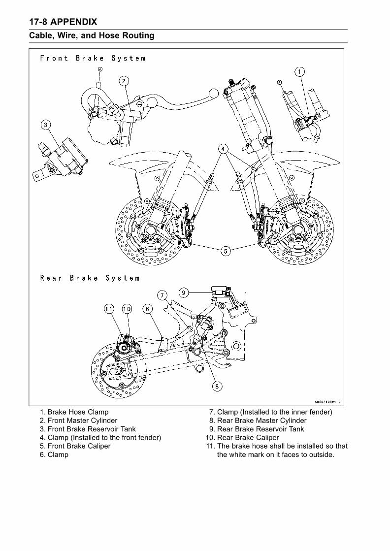
17-8 APPENDIX
Cable, Wire, and Hose Routing
1. Brake Hose Clamp2. Front Master Cylinder3. Front Brake Reservoir Tank4. Clamp (Installed to the front fender)5. Front Brake Caliper6. Clamp
7. Clamp (Installed to the inner fender)8. Rear Brake Master Cylinder9. Rear Brake Reservoir Tank10. Rear Brake Caliper11. The brake hose shall be installed so that
the white mark on it faces to outside.

APPENDIX 17-9
Cable, Wire, and Hose Routing
1. Radiator2. Reserve Tank Hose3. Coolant By-pass Hose4. Face the clamp screw rear and approximately 30° inside.5. Face the clamp screw downward.6. Face the white mark forward.7. To Cylinder Head Fitting8. Align the mark.9. To Reserve Tank10. Run the reserve tank hose under the starter motor lead.11. Run the reserve tank hose under the speed sensor lead.

17-10 APPENDIX
Cable, Wire, and Hose Routing
1. Radiator Fan Switch2. To Radiator3. Face the clamp screw downward.4. Cylinder Fitting.5. Water Pump.6. Align the mark.

APPENDIX 17-11
Cable, Wire, and Hose Routing
California Evaporative Emission Control System
1. Canister2. Band3. Face the hole downward.4. Separator5. Fitting6. Face the claw outside.7. To Separator (Blue)8. To Fuel Tank (Red)9. To Canister (Blue)10. To Throttle Body #4 (white)11. To Vacuum Switch(Green)
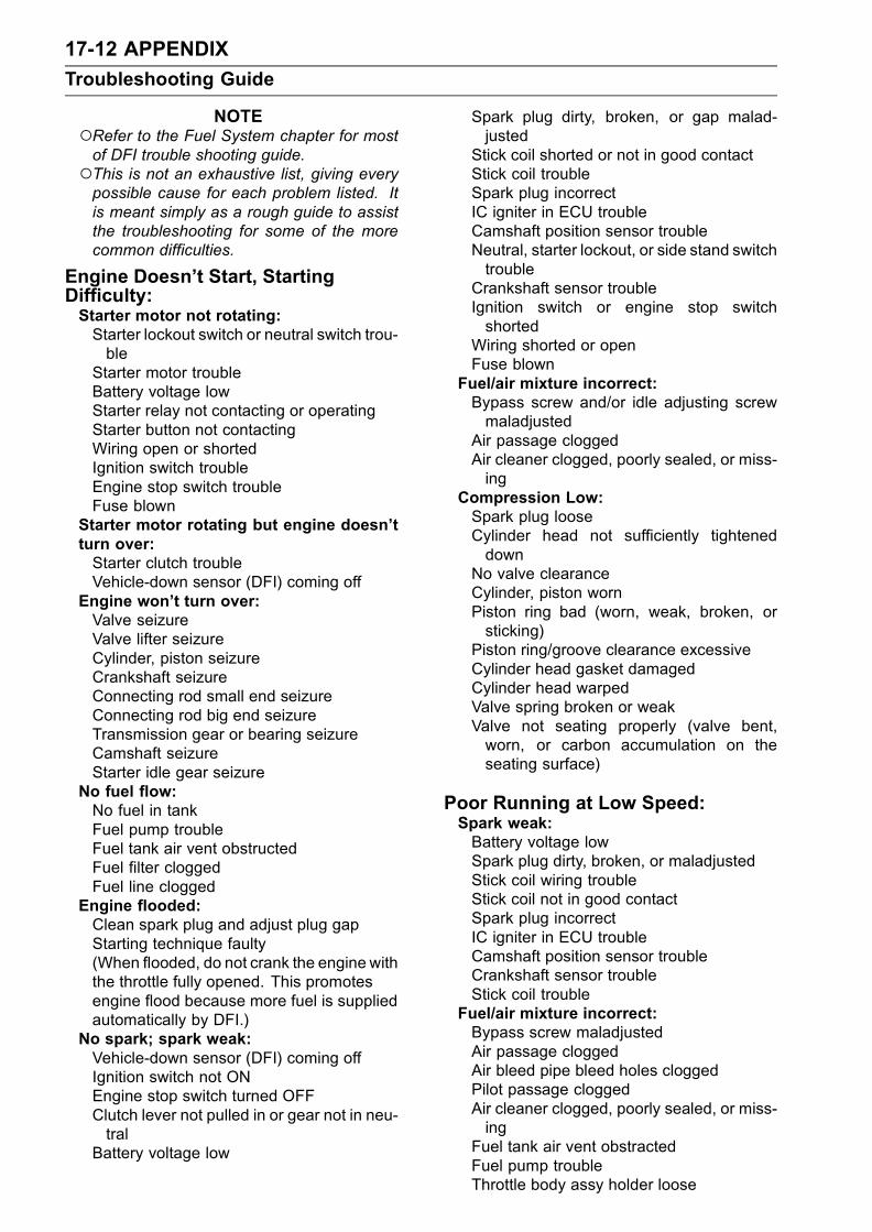
17-12 APPENDIX
Troubleshooting Guide
NOTERefer to the Fuel System chapter for mostof DFI trouble shooting guide.This is not an exhaustive list, giving everypossible cause for each problem listed. Itis meant simply as a rough guide to assistthe troubleshooting for some of the morecommon difficulties.
Engine Doesn’t Start, StartingDifficulty:Starter motor not rotating:Starter lockout switch or neutral switch trou-ble
Starter motor troubleBattery voltage lowStarter relay not contacting or operatingStarter button not contactingWiring open or shortedIgnition switch troubleEngine stop switch troubleFuse blown
Starter motor rotating but engine doesn’tturn over:Starter clutch troubleVehicle-down sensor (DFI) coming off
Engine won’t turn over:Valve seizureValve lifter seizureCylinder, piston seizureCrankshaft seizureConnecting rod small end seizureConnecting rod big end seizureTransmission gear or bearing seizureCamshaft seizureStarter idle gear seizure
No fuel flow:No fuel in tankFuel pump troubleFuel tank air vent obstructedFuel filter cloggedFuel line clogged
Engine flooded:Clean spark plug and adjust plug gapStarting technique faulty(When flooded, do not crank the engine withthe throttle fully opened. This promotesengine flood because more fuel is suppliedautomatically by DFI.)
No spark; spark weak:Vehicle-down sensor (DFI) coming offIgnition switch not ONEngine stop switch turned OFFClutch lever not pulled in or gear not in neu-tral
Battery voltage low
Spark plug dirty, broken, or gap malad-justed
Stick coil shorted or not in good contactStick coil troubleSpark plug incorrectIC igniter in ECU troubleCamshaft position sensor troubleNeutral, starter lockout, or side stand switchtrouble
Crankshaft sensor troubleIgnition switch or engine stop switchshorted
Wiring shorted or openFuse blown
Fuel/air mixture incorrect:Bypass screw and/or idle adjusting screwmaladjusted
Air passage cloggedAir cleaner clogged, poorly sealed, or miss-ing
Compression Low:Spark plug looseCylinder head not sufficiently tighteneddown
No valve clearanceCylinder, piston wornPiston ring bad (worn, weak, broken, orsticking)
Piston ring/groove clearance excessiveCylinder head gasket damagedCylinder head warpedValve spring broken or weakValve not seating properly (valve bent,worn, or carbon accumulation on theseating surface)
Poor Running at Low Speed:Spark weak:Battery voltage lowSpark plug dirty, broken, or maladjustedStick coil wiring troubleStick coil not in good contactSpark plug incorrectIC igniter in ECU troubleCamshaft position sensor troubleCrankshaft sensor troubleStick coil trouble
Fuel/air mixture incorrect:Bypass screw maladjustedAir passage cloggedAir bleed pipe bleed holes cloggedPilot passage cloggedAir cleaner clogged, poorly sealed, or miss-ing
Fuel tank air vent obstractedFuel pump troubleThrottle body assy holder loose

APPENDIX 17-13
Troubleshooting Guide
Air cleaner duct looseCompression low:Spark plug looseCylinder head not sufficiently tighteneddown
No valve clearanceCylinder, piston wornPiston ring bad (worn, weak, broken, orsticking)
Piston ring/groove clearance excessiveCylinder head warpedCylinder head gasket damagedValve spring broken or weakValve not seating properly (valve bent,worn, or carbon accumulation on theseating surface)
Other:IC igniter in ECU troubleThrottle body assy not synchronizingEngine oil viscosity too highDrive train troubleBrake draggingAir suction valve troubleVacuum switch valve troubleEngine overheatingClutch slipping
Poor Running or No Power at HighSpeed:Firing incorrect:Spark plug dirty, broken, or maladjustedStick coil wiring troubleStick coil not in good contactSpark plug incorrectCamshaft postion troubleIC igniter in ECU troubleCrankshaft sensor troubleStick coil trouble
Fuel/air mixture incorrect:Air cleaner clogged, poorly sealed, or miss-ing
Air cleaner O-ring damagedAir cleaner duct looseWater or foreign matter in fuelThrottle body assy holder looseFuel to injector insufficient (DFI)Fuel tank air vent obstructedFuel line cloggedFuel pump trouble (DFI)
Compression low:Spark plug looseCylinder head not sufficiently tighteneddown
No valve clearanceCylinder, piston wornPiston ring bad (worn, weak, broken, orsticking)
Piston ring/groove clearance excessiveCylinder head gasket damagedCylinder head warpedValve spring broken or weakValve not seating properly (valve bent,worn, or carbon accumulation on theseating surface.)
Knocking:Carbon built up in combustion chamberFuel poor quality or incorrectSpark plug incorrectIC igniter in ECU troubleCamshaft position sensor troubleCrankshaft sensor trouble
Miscellaneous:Throttle valve won’t fully openBrake draggingClutch slippingEngine overheatingEngine oil level too highEngine oil viscosity too highDrive train troubleAir suction valve troubleVacuum switch valve troubleCatalytic converter melt down due to muffleroverheating (KLEEN)
Overheating:Firing incorrect:Spark plug dirty, broken, or maladjustedSpark plug incorrectIC igniter in ECU trouble
Muffler overheating:For KLEEN, do not run the engine even ifwith only one cylinder misfiring or poorrunning (Request the nearest service fa-cility to correct it)
For KLEEN, do not push-start with a deadbattery (Connect another full-chargedbattery with jumper cables, and start theengine using the electric starter)
For KLEEN, do not start the engine undermisfire due to spark plug fouling or poorconnection of the stick coil
For KLEEN, do not coast the motorcyclewith the ignition switch off (Turn the igni-tion switch ON and run the engine)
IC igniter in ECU troubleFuel/air mixture incorrect:Throttle body assy holder looseAir cleaner duct looseAir cleaner poorly sealed, or missingAir cleaner O-ring damagedAir cleaner clogged
Compression high:Carbon built up in combustion chamber

17-14 APPENDIX
Troubleshooting Guide
Engine load faulty:Clutch slippingEngine oil level too highEngine oil viscosity too highDrive train troubleBrake dragging
Lubrication inadequate:Engine oil level too lowEngine oil poor quality or incorrect
Oil cooler incorrect:Oil cooler clogged
Gauge incorrect:Water temperature gauge brokenWater temperature sensor broken
Coolant incorrect:Coolant level too lowCoolant deterioratedWrong coolant mixed ratio
Cooling system component incorrect:Radiator fin damagedRadiator cloggedThermostat troubleRadiator cap troubleRadiator fan switch troubleRadiator fan relay troubleFan motor brokenFan blade damagedWater pump not turningWater pump impeller damaged
Over Cooling:Gauge incorrect:Water temperature gauge brokenWater temperature sensor broken
Cooling system component incorrect:Radiator fan switch troubleThermostat trouble
Clutch Operation Faulty:Clutch slipping:Friction plate worn or warpedSteel plate worn or warpedClutch spring broken or weakClutch hub or housing unevenly wornNo clutch lever playClutch inner cable troubleClutch release mechanism trouble
Clutch not disengaging properly:Clutch plate warped or too roughClutch spring compression unevenEngine oil deterioratedEngine oil viscosity too highEngine oil level too highClutch housing frozen on drive shaftClutch hub nut looseClutch hub spline damagedClutch friction plate installed wrong
Clutch lever play excessiveClutch release mechanism trouble
Gear Shifting Faulty:Doesn’t go into gear; shift pedal doesn’treturn:Clutch not disengagingShift fork bent or seizedGear stuck on the shaftGear positioning lever bindingShift return spring weak or brokenShift return spring pin looseShift mechanism arm spring brokenShift mechanism arm brokenShift pawl broken
Jumps out of gear:Shift fork ear worn, bentGear groove wornGear dogs and/or dog holes wornShift drum groove wornGear positioning lever spring weak or bro-ken
Shift fork guide pin wornDrive shaft, output shaft, and/or gearsplines worn
Overshifts:Gear positioning lever spring weak or bro-ken
Shift mechanism arm spring broken
Abnormal Engine Noise:Knocking:IC igniter in ECU troubleCarbon built up in combustion chamberFuel poor quality or incorrectSpark plug incorrectOverheating
Piston slap:Cylinder/piston clearance excessiveCylinder, piston wornConnecting rod bentPiston pin, piston pin hole worn
Valve noise:Valve clearance incorrectValve spring broken or weakCamshaft bearing wornValve lifter worn
Other noise:Connecting rod small end clearance exces-sive
Connecting rod big end clearance exces-sive
Piston ring/groove clearance excessivePiston ring worn, broken, or stuckPiston ring groove wornPiston seizure, damageCylinder head gasket leaking

APPENDIX 17-15
Troubleshooting Guide
Exhaust pipe leaking at cylinder head con-nection
Crankshaft runout excessiveEngine mount looseCrankshaft bearing wornPrimary gear worn or chippedCamshaft chain tensioner troubleCamshaft chain, sprocket, guide wornAir suction valve damagedVacuum switch valve damagedAlternator rotor looseCatalytic converter melt down due tomuffleroverheating (KLEEN)
Abnormal Drive Train Noise:Clutch noise:Clutch damper weak or damagedClutch housing/friction plate clearance ex-cessive
Clutch housing gear wornWrong installation of outside friction plate
Transmission noise:Bearings wornTransmission gear worn or chippedMetal chips jammed in gear teethEngine oil insufficient
Drive line noise:Drive chain adjusted improperlyDrive chain wornRear and/or engine sprocket wornChain lubrication insufficientRear wheel misaligned
Abnormal Frame Noise:Front fork noise:Oil insufficient or too thinSpring weak or broken
Rear shock absorber noise:Shock absorber damaged
Disc brake noise:Pad installed incorrectlyPad surface glazedDisc warpedCaliper trouble
Other noise:Bracket, nut, bolt, etc. not properlymounted or tightened
Oil Pressure Warning Light Goes On:Engine oil pump damagedEngine oil screen cloggedEngine oil filter cloggedEngine oil level too lowEngine oil viscosity too lowCamshaft bearing wornCrankshaft bearing worn
Oil pressure switch damagedWiring faultyRelief valve stuck openO-ring at the oil passage in the crankcasedamaged
Exhaust Smokes Excessively:White smoke:Piston oil ring wornCylinder wornValve oil seal damagedValve guide wornEngine oil level too high
Black smoke:Air cleaner clogged
Brown smoke:Air cleaner duct looseAir cleaner O-ring damagedAir cleaner poorly sealed or missing
Handling and/or StabilityUnsatisfactory:Handlebar hard to turn:Cable routing incorrectHose routing incorrectWiring routing incorrectSteering stem nut too tightSteering stem bearing damagedSteering stem bearing lubrication inade-quate
Steering stem bentTire air pressure too low
Handlebar shakes or excessively vibrates:Tire wornSwingarm pivot bearing wornRim warped, or not balancedWheel bearing wornHandlebar clamp bolt looseSteering stem nut looseFront, rear axle runout excessiveEngine mounting bolt loose
Handlebar pulls to one side:Frame bentWheel misalignmentSwingarm bent or twistedSwingarm pivot shaft runout excessiveSteering maladjustedFront fork bentRight and left front fork oil level uneven
Shock absorption unsatisfactory:(Too hard)Front fork oil excessiveFront fork oil viscosity too highRear shock absorber adjustment too hardTire air pressure too highFront fork bent(Too soft)
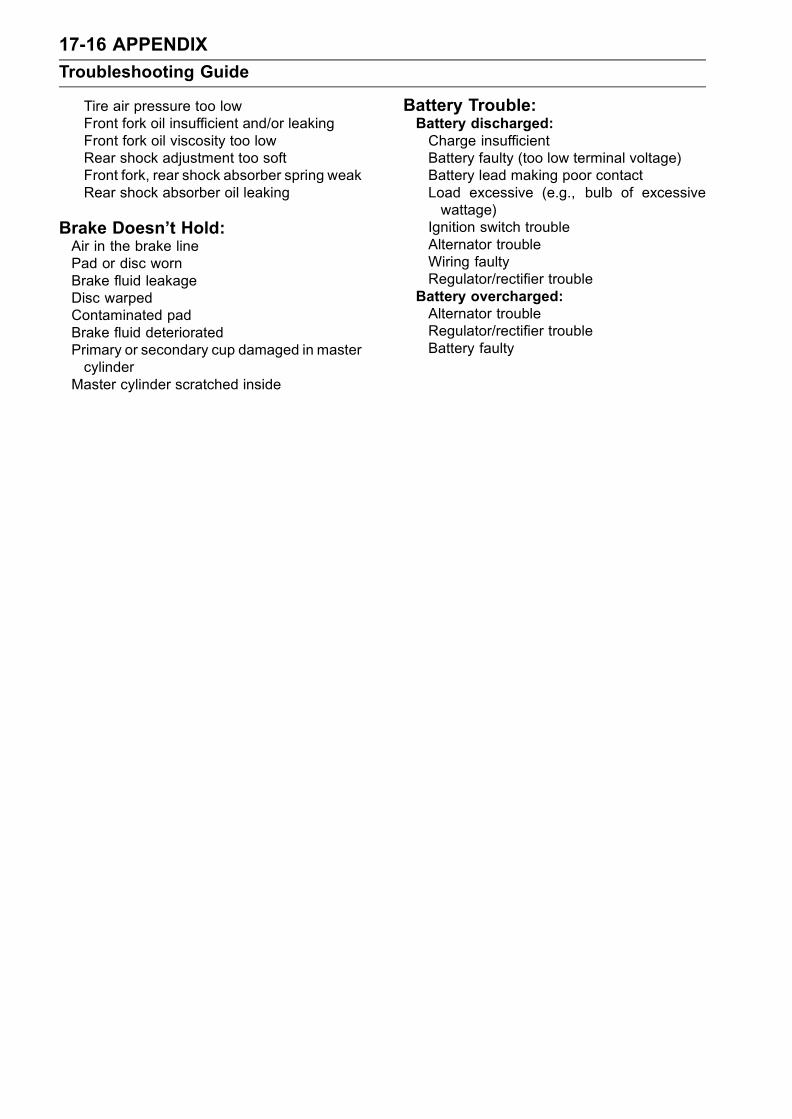
17-16 APPENDIX
Troubleshooting Guide
Tire air pressure too lowFront fork oil insufficient and/or leakingFront fork oil viscosity too lowRear shock adjustment too softFront fork, rear shock absorber spring weakRear shock absorber oil leaking
Brake Doesn’t Hold:Air in the brake linePad or disc wornBrake fluid leakageDisc warpedContaminated padBrake fluid deterioratedPrimary or secondary cup damaged in mastercylinder
Master cylinder scratched inside
Battery Trouble:Battery discharged:Charge insufficientBattery faulty (too low terminal voltage)Battery lead making poor contactLoad excessive (e.g., bulb of excessivewattage)
Ignition switch troubleAlternator troubleWiring faultyRegulator/rectifier trouble
Battery overcharged:Alternator troubleRegulator/rectifier troubleBattery faulty
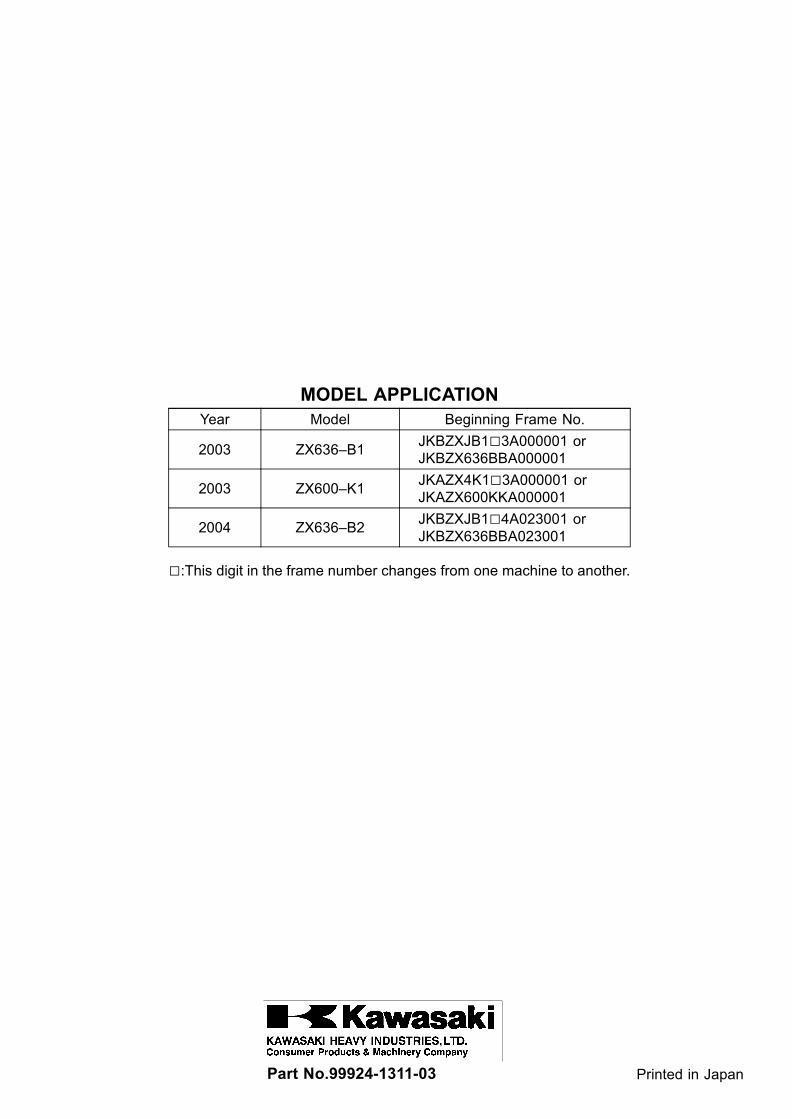
MODEL APPLICATIONYear Model Beginning Frame No.
2003 ZX636–B1JKBZXJB13A000001 orJKBZX636BBA000001
2003 ZX600–K1JKAZX4K13A000001 orJKAZX600KKA000001
2004 ZX636–B2JKBZXJB14A023001 orJKBZX636BBA023001
:This digit in the frame number changes from one machine to another.
Part No.99924-1311-03 Printed in Japan