module 7 simple beam theory - mitweb.mit.edu/16.20/homepage/7_simplebeamtheory/simplebeamthe… ·...
TRANSCRIPT
Module 7
Simple Beam Theory
Learning Objectives
• Review simple beam theory
• Generalize simple beam theory to three dimensions and general cross sections
• Consider combined effects of bending, shear and torsion
• Study the case of shell beams
7.1 Review of simple beam theory
Readings: BC 5 Intro, 5.1
A beam is a structure which has one of its dimensions much larger than the other two.The importance of beam theory in structural mechanics stems from its widespread successin practical applications.
7.1.1 Kinematic assumptions
Readings: BC 5.2
Beam theory is founded on the following two key assumptions known as the Euler-Bernoulli assumptions:
• Cross sections of the beam do not deform in a significant manner under the applicationof transverse or axial loads and can be assumed as rigid
Concept Question 7.1.1. With reference to Figure 7.1,
1. what is the main implication of this assumption on the kinematic description(overall displacement field) of the cross section? Solution:The cross section can only undergo a rigid-body motion in its plane, i.e. two rigidbody translations and one rotation.
151
152 MODULE 7. SIMPLE BEAM THEORY
e2
e3
e1
u2
u3
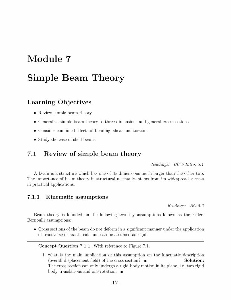
Figure 7.1: First kinematic assumption in Euler-Bernoulli beam theory: rigid in-plane de-formation of cross sections.
2. To simplify further the discussion, assume for now that there is no rotation of thecross section around the e3 axis. Write the most general form of the cross-sectionin-plane displacement components: Solution: The cross section can onlytranslate rigidly in the e2 and e3 directions, i.e. the displacement components inthe plane cannot depend on the position in the plane x2, x3 and:
u2(x1, x2, x3) = u2(x1), u3(x1, x2, x3) = u3(x1) (7.1)
• During deformation, the cross section of the beam is assumed to remain planar andnormal to the deformed axis of the beam.
Concept Question 7.1.2. With reference to Figure 7.3,
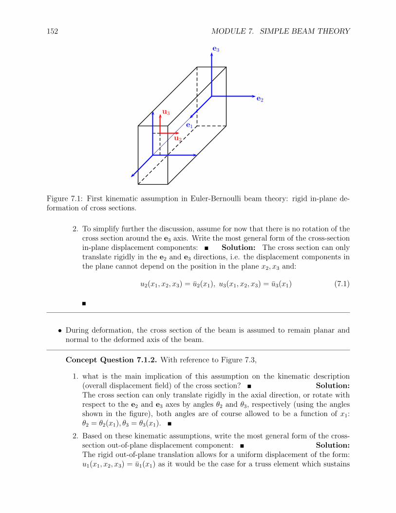
1. what is the main implication of this assumption on the kinematic description(overall displacement field) of the cross section? Solution:The cross section can only translate rigidly in the axial direction, or rotate withrespect to the e2 and e3 axes by angles θ2 and θ3, respectively (using the anglesshown in the figure), both angles are of course allowed to be a function of x1:θ2 = θ2(x1), θ3 = θ3(x1).
2. Based on these kinematic assumptions, write the most general form of the cross-section out-of-plane displacement component: Solution:The rigid out-of-plane translation allows for a uniform displacement of the form:u1(x1, x2, x3) = u1(x1) as it would be the case for a truss element which sustains
7.1. REVIEW OF SIMPLE BEAM THEORY 153
e2
e3
e1
(a)
e2
e3
e1
θ2(x1)
(b)
e2
e3
e1θ3(x1)
(c)
Figure 7.2: Second kinematic assumption in Euler-Bernoulli beam theory: cross sectionsremain planar after deformation.
154 MODULE 7. SIMPLE BEAM THEORY
a uniform uni-axial strain. The rotations θ2 and θ3 will give contributions to thetotal axial displacement which are linear in the in-plane coordinates x3 and x2
respectively, see Figure 7.3. It can be easily inferred from the figure that thesecontributions adopt the form: x3θ2(x1) and −x2θ3(x1), respectively. It should becarefully noted that assuming both positive angles, this contribution indeed hasa negative sign.
In summary, the out-of-plane kinematic restrictions imposed by the second Euler-Bernoulli assumption results in the following form of the u1 displacement compo-nent:
u1(x1, x2, x3) = u1(x1) + x3θ2(x1)− x2θ3(x1) (7.2)
It should be noted that we have not defined the origin of the coordinate systembut we have implicitly assumed that it corresponds to the intersection of the lineswhich do not exhibit stretch or contraction under out-of-plane rotations of thecross sections. Later we will define these lines as the neutral axes for bending.
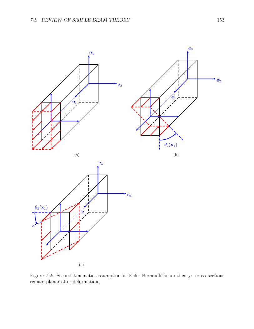
3. If you noticed, we have not applied the constraint that the sections must remainnormal to the deformed axis of the beam. Use this part of the assumption toestablish a relation between the displacements fields u2(x1), u3(x1) and the anglefields θ2(x1), θ3(x1), respectively, see Figure ??.
θ2
u3(x1)
e1
e3
bc+e2
(a)
θ3
u2(x1)
e1
e2
bcbe3
(b)
Figure 7.3: Implications of the assumption that cross sections remain normal to the axis ofthe beam upon deformation.
Solution: from the figure one can see clearly that:
θ2 = −du3
dx1
, θ3 =du2
dx1
(7.3)
7.1. REVIEW OF SIMPLE BEAM THEORY 155
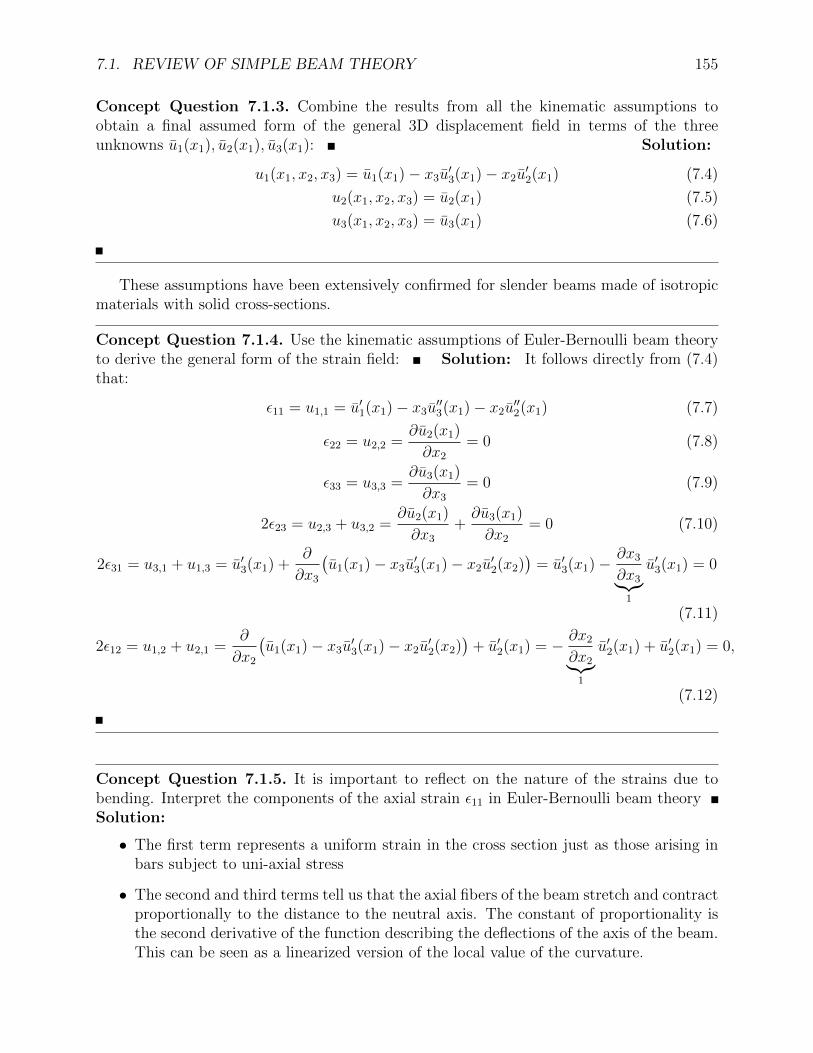
Concept Question 7.1.3. Combine the results from all the kinematic assumptions toobtain a final assumed form of the general 3D displacement field in terms of the threeunknowns u1(x1), u2(x1), u3(x1): Solution:
u1(x1, x2, x3) = u1(x1)− x3u′3(x1)− x2u
′2(x1) (7.4)
u2(x1, x2, x3) = u2(x1) (7.5)
u3(x1, x2, x3) = u3(x1) (7.6)
These assumptions have been extensively confirmed for slender beams made of isotropicmaterials with solid cross-sections.
Concept Question 7.1.4. Use the kinematic assumptions of Euler-Bernoulli beam theoryto derive the general form of the strain field: Solution: It follows directly from (7.4)that:
ε11 = u1,1 = u′1(x1)− x3u′′3(x1)− x2u
′′2(x1) (7.7)
ε22 = u2,2 =∂u2(x1)
∂x2
= 0 (7.8)
ε33 = u3,3 =∂u3(x1)
∂x3
= 0 (7.9)
2ε23 = u2,3 + u3,2 =∂u2(x1)
∂x3
+∂u3(x1)
∂x2
= 0 (7.10)
2ε31 = u3,1 + u1,3 = u′3(x1) +∂
∂x3
(u1(x1)− x3u
′3(x1)− x2u
′2(x2)
)= u′3(x1)− ∂x3
∂x3︸︷︷︸1
u′3(x1) = 0
(7.11)
2ε12 = u1,2 + u2,1 =∂
∂x2
(u1(x1)− x3u
′3(x1)− x2u
′2(x2)
)+ u′2(x1) = − ∂x2
∂x2︸︷︷︸1
u′2(x1) + u′2(x1) = 0,
(7.12)
Concept Question 7.1.5. It is important to reflect on the nature of the strains due tobending. Interpret the components of the axial strain ε11 in Euler-Bernoulli beam theorySolution:
• The first term represents a uniform strain in the cross section just as those arising inbars subject to uni-axial stress
• The second and third terms tell us that the axial fibers of the beam stretch and contractproportionally to the distance to the neutral axis. The constant of proportionality isthe second derivative of the function describing the deflections of the axis of the beam.This can be seen as a linearized version of the local value of the curvature.
156 MODULE 7. SIMPLE BEAM THEORY
• There are no shear strains!!!! This is a direct consequence of assuming that the cross-section remains normal to the deformed axis of the beam.
• There are no strains in the plane. This is a direct consequence of assuming that thecross section is rigid.
One of the main conclusions of the Euler-Bernoulli assumptions is that in this par-ticular beam theory the primary unknown variables are the three displacement functionsu1(x1), u2(x1), u3(x1) which are only functions of x1. The full displacement, strain and there-fore stress fields do depend on the other independent variables but in a prescribed way thatfollows directly from the kinematic assumptions and from the equations of elasticity. Thepurpose of formulating a beam theory is to obtain a description of the problem expressedentirely on variables that depend on a single independent spatial variable x1 which is thecoordinate along the axis of the beam.
7.1.2 Definition of stress resultants
Readings: BC 5.3
Stress resultants are equivalent force systems that represent the integral effect of theinternal stresses acting on the cross section. Thus, they eliminate the need to carry over thedependency of the stresses on the spatial coordinates of the cross section x2, x3.
The axial or normal force is defined by the expression:
N1(x1) =
∫A
σ11(x1, x2, x3)dA (7.13)
The transverse shearing forces are defined by the expressions:
V2(x1) =
∫A
σ12(x1, x2, x3)dA (7.14)
V3(x1) =
∫A
σ13(x1, x2, x3)dA (7.15)
(7.16)
The bending moments are defined by the expressions:
M2(x1) =
∫A
x3σ11(x1, x2, x3)dA (7.17)
M3(x1) = −∫A
x2σ11(x1, x2, x3)dA (7.18)
(7.19)
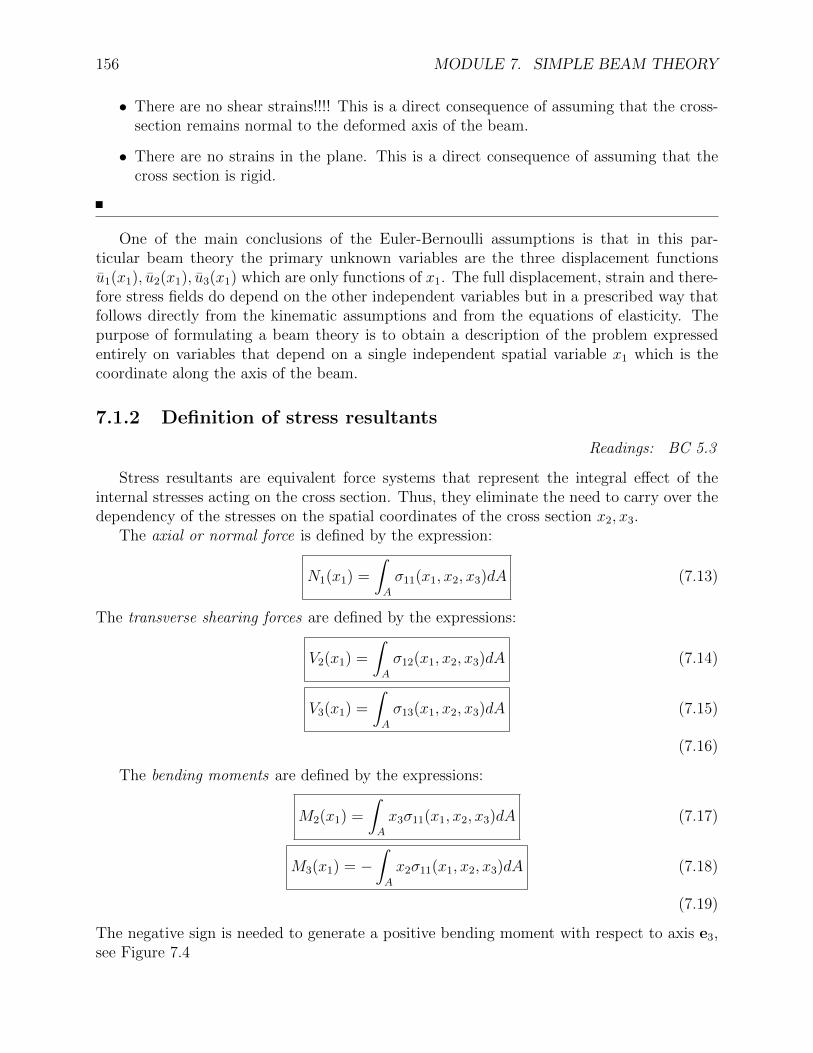
The negative sign is needed to generate a positive bending moment with respect to axis e3,see Figure 7.4
7.2. AXIAL LOADING OF BEAMS 157
dx1
N1 V3
M2
N1
V3
M2
e1
e3
bc×e2
σ13
σ11
σ11
σ13
dx1
N1 V2
M3
N1
V2
M3
e1
e2
bcbe3
σ12
σ11
σ11
σ12
Figure 7.4: Sign conventions for the sectional stress resultants
7.2 Axial loading of beams
Readings: BC 5.4
L
p1(x1)
P1
e1
e2
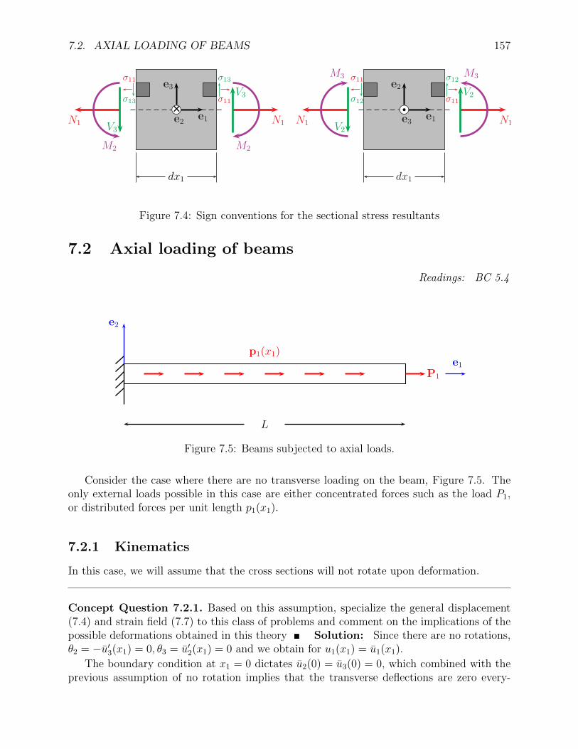
Figure 7.5: Beams subjected to axial loads.
Consider the case where there are no transverse loading on the beam, Figure 7.5. Theonly external loads possible in this case are either concentrated forces such as the load P1,or distributed forces per unit length p1(x1).
7.2.1 Kinematics
In this case, we will assume that the cross sections will not rotate upon deformation.
Concept Question 7.2.1. Based on this assumption, specialize the general displacement(7.4) and strain field (7.7) to this class of problems and comment on the implications of thepossible deformations obtained in this theory Solution: Since there are no rotations,θ2 = −u′3(x1) = 0, θ3 = u′2(x1) = 0 and we obtain for u1(x1) = u1(x1).
The boundary condition at x1 = 0 dictates u2(0) = u3(0) = 0, which combined with theprevious assumption of no rotation implies that the transverse deflections are zero every-

158 MODULE 7. SIMPLE BEAM THEORY
where, u2(x1) = u3(x1) = 0. The displacement field is then:
u1(x1, x2, x3) = u1(x1)
u2(x1, x2, x3) = 0
u3(x1, x2, x3) = 0
The strain field follows directly from this as:
ε11(x1, x2, x3) = u′1(x1)
and all the other strain components are zero. The assumption of allowing only rigid motionsof the cross section implies that there cannot be any in-plane strains. This creates a stateof uni-axial strain.
7.2.2 Constitutive law for the cross section
We will assume a linear-elastic isotropic material and that the transverse stresses σ22, σ33 ∼ 0.By Hooke’s law, the axial stress σ11 is given by:
σ11(x1, x2, x3) = Eε11(x1, x2, x3)
Replacing the strain field for this case:
σ11(x1, x2, x3) = Eu′1(x1) (7.20)
In other words, we are assuming a state of uni-axial stress.
Concept Question 7.2.2. This exposes an inconsistency in Euler-Bernoulli beam theory.What is it and how can we justify it? Solution: The inconsistency isthat we are assuming the kinematics to be uni-axial strain, and the kinetics to be uni-axialstress. In other words one can either have:
ε22 = ε33 = 0
(Euler-Bernoulli hypothesis) orσ22 = σ33 = 0
These two cannot co-exist except when the Poisson ratio is zero. However, this in generalhas a small effect in most problems of practical interest. The theory is developed assumingthat we can ignore both these strains and stresses.
The axial force can be obtained by replacing (7.20) in (7.13):
N1(x1) =
∫A(x1)
Eu′1(x1)dA =
∫A(x1)
EdA︸ ︷︷ ︸S(x1)
u′1(x1)
7.2. AXIAL LOADING OF BEAMS 159
We will define:
S(x1) =
∫A(x1)
E(x1, x2, x3)dA (7.21)
as the axial stiffness of the beam, where we allow the Young’s modulus to vary freely bothin the cross section and along the axis of the beam, and we allow for non-uniform crosssection geometries. In the case that the section is homogeneous in the cross section (E =E(x1,��x2,��x3)), we obtain: S(x1) = E(x1)A(x1) (This may happen for example in functionally-graded materials). Further, if the section is uniform along x1 and the material is homogeneous(E = const), we obtain: S = EA.
We can then write a constitutive relation between the axial force and the appropriatemeasure of strain for the beam:
N1(x1) = S(x1)u′1(x1) (7.22)
e3
e2
xi3
xi+13
i = n, En
i, Ei
i = 1, E1
w
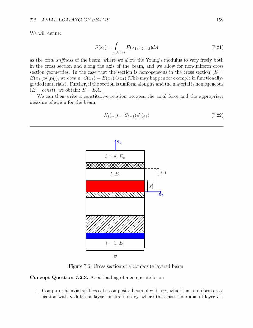
Figure 7.6: Cross section of a composite layered beam.
Concept Question 7.2.3. Axial loading of a composite beam
1. Compute the axial stiffness of a composite beam of width w, which has a uniform crosssection with n different layers in direction e3, where the elastic modulus of layer i is
160 MODULE 7. SIMPLE BEAM THEORY
Ei and its thickness is ti = xi+13 − xi3, as shown in the figure. Solution: From
equation (7.21),
S =
∫A(x1)
E(x1, x2, x3)dA =n∑i=1
∫Ai
EidAi =n∑i=1
Ei
∫Ai
dAi
=n∑i=1
Ei b
ti︷ ︸︸ ︷(xi+1
3 − xi3)︸ ︷︷ ︸Ai
Note that we could define an effective weighted averaged Young’s modulus Eeff suchthat:
S = EeffA =n∑i=1
EiAi,⇒ Eeff =n∑i=1
AiAEi
2. Compute the stress distribution in the cross section assuming the axial force distribu-tion N1(x1) is known: Solution: Recalling that the axial strain at x1 is uniformε11 = u′(x1), and that the stress is given by (7.20), we obtain:
σ11(x1, x2, xi3 < x3 < xi+1
3 ) = Eiu′(x1) =Ei
SN1(x1) (7.23)
3. Interpret the stress distribution obtained. Solution: The stress isdiscontinuous in the cross section. As the section is forced to deform uniformly in theaxial direction, layers that are stiffer develop higher stresses
Having completed a kinematic and constitutive description, it remains to formulate anappropriate way to enforce equilibrium of beams loaded axially.
7.2.3 Equilibrium equations
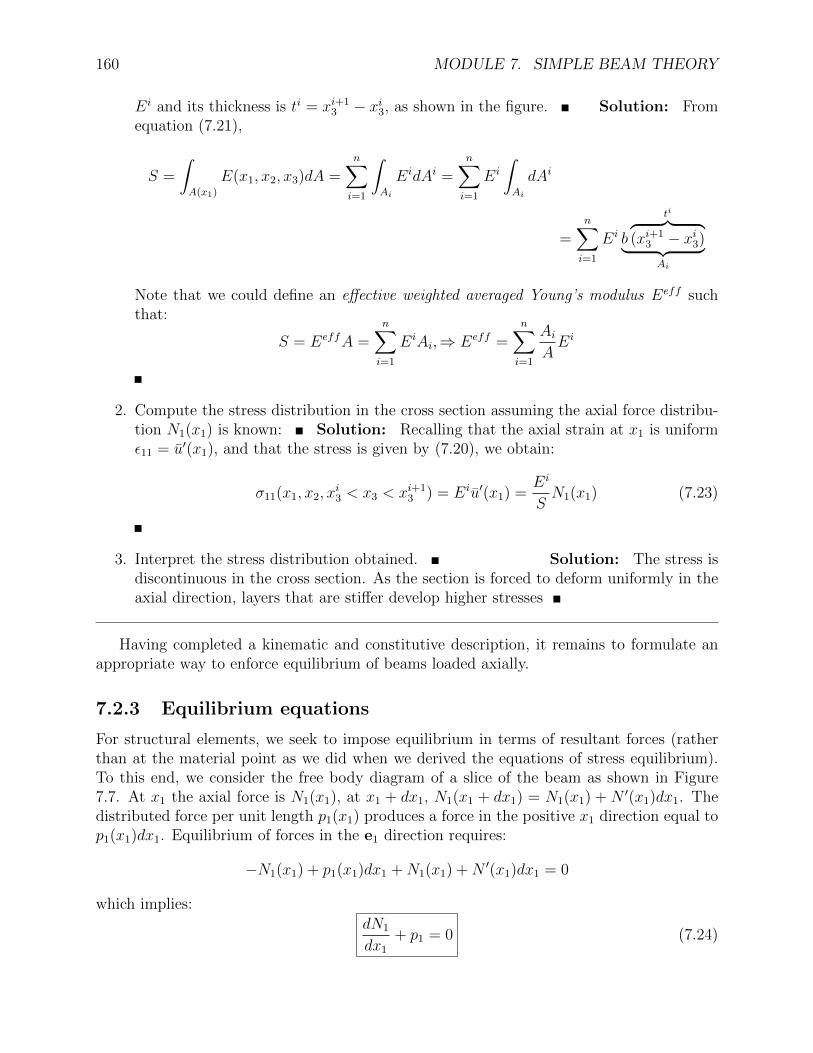
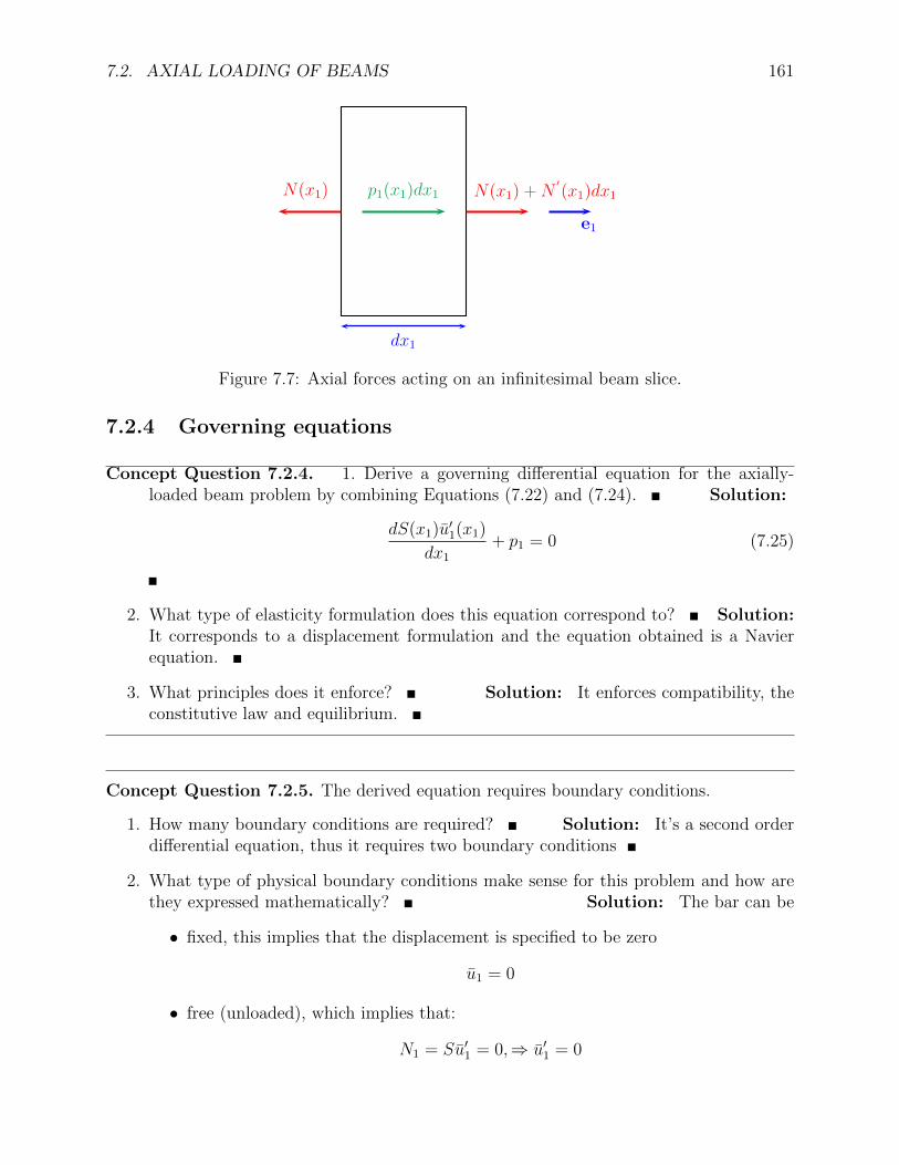
For structural elements, we seek to impose equilibrium in terms of resultant forces (ratherthan at the material point as we did when we derived the equations of stress equilibrium).To this end, we consider the free body diagram of a slice of the beam as shown in Figure7.7. At x1 the axial force is N1(x1), at x1 + dx1, N1(x1 + dx1) = N1(x1) + N ′(x1)dx1. Thedistributed force per unit length p1(x1) produces a force in the positive x1 direction equal top1(x1)dx1. Equilibrium of forces in the e1 direction requires:
−N1(x1) + p1(x1)dx1 +N1(x1) +N ′(x1)dx1 = 0
which implies:
dN1
dx1
+ p1 = 0 (7.24)
7.2. AXIAL LOADING OF BEAMS 161
dx1
N(x1) +N′
(x1)dx1N(x1) p1(x1)dx1
e1
Figure 7.7: Axial forces acting on an infinitesimal beam slice.
7.2.4 Governing equations
Concept Question 7.2.4. 1. Derive a governing differential equation for the axially-loaded beam problem by combining Equations (7.22) and (7.24). Solution:
dS(x1)u′1(x1)
dx1
+ p1 = 0 (7.25)
2. What type of elasticity formulation does this equation correspond to? Solution:It corresponds to a displacement formulation and the equation obtained is a Navierequation.
3. What principles does it enforce? Solution: It enforces compatibility, theconstitutive law and equilibrium.
Concept Question 7.2.5. The derived equation requires boundary conditions.
1. How many boundary conditions are required? Solution: It’s a second orderdifferential equation, thus it requires two boundary conditions
2. What type of physical boundary conditions make sense for this problem and how arethey expressed mathematically? Solution: The bar can be
• fixed, this implies that the displacement is specified to be zero
u1 = 0
• free (unloaded), which implies that:
N1 = Su′1 = 0,⇒ u′1 = 0
162 MODULE 7. SIMPLE BEAM THEORY
• subjected to a concentrated load P1, which implies that:
N1 = Su′1 = P1
This completes the formulation for axially-loaded beams.
L
e1
e2
w
A0
A1 = A0/2
Figure 7.8: Schematic of a helicopter blade rotating at an angular speed ω
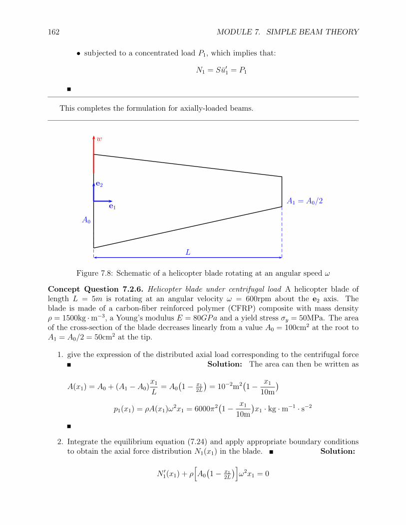
Concept Question 7.2.6. Helicopter blade under centrifugal load A helicopter blade oflength L = 5m is rotating at an angular velocity ω = 600rpm about the e2 axis. Theblade is made of a carbon-fiber reinforced polymer (CFRP) composite with mass densityρ = 1500kg ·m−3, a Young’s modulus E = 80GPa and a yield stress σy = 50MPa. The areaof the cross-section of the blade decreases linearly from a value A0 = 100cm2 at the root toA1 = A0/2 = 50cm2 at the tip.
1. give the expression of the distributed axial load corresponding to the centrifugal forceSolution: The area can then be written as
A(x1) = A0 + (A1 − A0)x1
L= A0
(1− x1
2L
)= 10−2m2
(1− x1
10m
)p1(x1) = ρA(x1)ω2x1 = 6000π2
(1− x1
10m
)x1 · kg ·m−1 · s−2
2. Integrate the equilibrium equation (7.24) and apply appropriate boundary conditionsto obtain the axial force distribution N1(x1) in the blade. Solution:
N ′1(x1) + ρ[A0
(1− x1
2L
)]ω2x1 = 0
7.3. BEAM BENDING 163
N1(x1) = ρω2A0x21
( x1
6L− 1
2
)+ C
The boundary condition is: N1(L) = 0, let’s go ahead and apply it:
0 = ρω2A0L2(��L
6��L− 1
2
)︸ ︷︷ ︸
−1/3
+C ⇒ C =1
3ρω2A0L
2
Replacing in the previous expression:
N1(x1) =1
6ρω2L2A0(η3 − 3η2 + 2
)where we defined η = x1/L.
3. What is the maximum axial force and where does it happen? Solution: Themaximum in the range 0 ≤ η ≤ 1 is at η = 0. The maximum happens at x1 = 0 andthe value is: Nmax
1 = N1(0) = 13ρω2L2A0 = 685389N
4. Provide an expression for the axial stress distribution σ11(x1) Solution:
σ11(x1) =N1(x1)
A(x1)=
16ρω2L2
��A0(η3 − 3η2 + 2)
��A0
(1− η
2
)
5. What is the maximum stress, where does it happen, does the material yield?Solution: For the values given, one can find the maximum to be σmax11 = 36MPa andit happens at x1 = 0.194L. There is no yielding as σmax11 < σy and we are consideringuni-axial stress.
6. The displacement can be obtained by integrating the strain:
ε11 = u′1(x1) =σ11(x1)
E
and applying the boundary condition u1(0) = 0. The solution can be readily found tobe:
u1(x1) =ρω2L3
3E
[2η +
η2
2− η3
3+ 2 log
(1− η
2
)]Verify that the correct strain is obtained and that the boundary condition is satisfied:
Solution: The boundary condition is readily verified. The strain is:
u′1(x1) =ρω2L3
3E
[2 + η − η2 − 1
1− η2
]which is the same as we obtained above.
164 MODULE 7. SIMPLE BEAM THEORY
L
p2(x1) P2
e1
e2
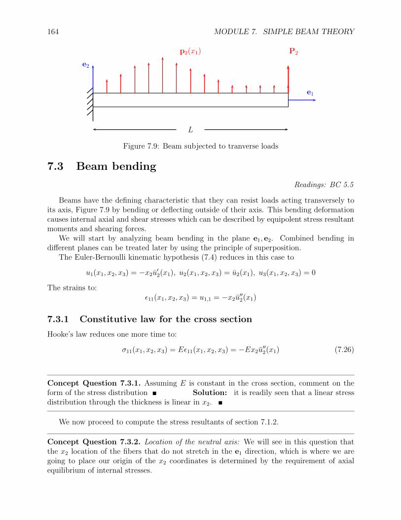
Figure 7.9: Beam subjected to tranverse loads
7.3 Beam bending
Readings: BC 5.5
Beams have the defining characteristic that they can resist loads acting transversely toits axis, Figure 7.9 by bending or deflecting outside of their axis. This bending deformationcauses internal axial and shear stresses which can be described by equipolent stress resultantmoments and shearing forces.
We will start by analyzing beam bending in the plane e1, e2. Combined bending indifferent planes can be treated later by using the principle of superposition.
The Euler-Bernoulli kinematic hypothesis (7.4) reduces in this case to
u1(x1, x2, x3) = −x2u′2(x1), u2(x1, x2, x3) = u2(x1), u3(x1, x2, x3) = 0
The strains to:ε11(x1, x2, x3) = u1,1 = −x2u
′′2(x1)
7.3.1 Constitutive law for the cross section
Hooke’s law reduces one more time to:
σ11(x1, x2, x3) = Eε11(x1, x2, x3) = −Ex2u′′2(x1) (7.26)
Concept Question 7.3.1. Assuming E is constant in the cross section, comment on theform of the stress distribution Solution: it is readily seen that a linear stressdistribution through the thickness is linear in x2.
We now proceed to compute the stress resultants of section 7.1.2.
Concept Question 7.3.2. Location of the neutral axis: We will see in this question thatthe x2 location of the fibers that do not stretch in the e1 direction, which is where we aregoing to place our origin of the x2 coordinates is determined by the requirement of axialequilibrium of internal stresses.
7.3. BEAM BENDING 165
1. The only applied external forces are in the e2 direction. Based on this, what can yousay about the axial force N1(x1)?
Solution: From force equilibrium in direction e1 we conclude that the axial forcemust vanish at all cross sections x1, i.e. N1(x1) = 0,∀x1
2. Write the expression for the axial force Solution: From equation (7.13)
N1(x1) =
∫A(x1)
σ11(x1, x2, x3)dA =
∫A(x1)
(−1)Ex2u′′2(x1)dA = (−1)
[∫A(x1)
Ex2dA
]u′′2(x1)
3. From here, obtain an expression that enforces equilibrium in the e1 direction. Interpretits meaning Solution: Setting the axial force to zero, and noticing that thecurvature u′′2(x1) 6= 0, we obtain that the square bracket in the previous relation mustvanish: ∫
A(x1)
Ex2dA = 0
This can be interpreted as a modulus-weighted first moment of area of the cross section.For uniform E, we obtain simply:
∫A(x1)
x2dA = 0.
4. Define the modulus-weighted centroid of the cross section by the condition:
S(x1)xc2(x1) =
∫A(x1)
Ex2dA, ⇒ xc2(x1) =1
S(x1)
∫A(x1)
Ex2dA
and interpret the meaning of using xc2 as the origin of the coordinate system So-lution: it can be seen that setting the zero for x2 at xc2, the modulus-weighted firstmoment of area of the cross section vanishes.
5. Compare the location of the modulus-weighted centroid, the center of mass and thecenter of area for a general cross section and for a homogeneous one Solution:
xc2 =
∫AEx2dA∫
A(x1)EdA
, xm2 =
∫Aρx2dA∫aρdA
, xa2 =
∫Ax2dA∫AdA
These locations don’t match in general. For homogeneous cross sections:
xc2 =��E∫Ax2dA
��E∫AdA
= xm2 = �ρ∫Ax2dA
�ρ∫AdA
= xa2 =
∫Ax2dA∫AdA
, they do.
We now consider the internal bending moment.
166 MODULE 7. SIMPLE BEAM THEORY
Concept Question 7.3.3. Specialize the definition of the M3 stress resultant (7.17)
M3(x1) = −∫A(x1)
x2σ11(x1, x2, x3)dA
to the case under consideration by using the stress distribution resulting from the Euler-Bernoulli hypothesis, σ11(x1, x2, x3) = −Ex2u
′′2(x1) to obtain a relation between the bending
moment and the local curvature u′′2(x1).Solution: By direct substitution and some algebraic manipulation we obtain:
M3(x1) =��−∫A(x1)
x2���(−1)Ex2u
′′2(x1)dA =
[∫A(x1)
Ex22dA
]︸ ︷︷ ︸
Hc33(x1)
u′′2(x1)
We can see that we obtain a linear relation between the bending moment and the localcurvature ( moment-curvature relationship):
M3(x1) = Hc33(x1)u′′2(x1) (7.27)
The constant of proportionality will be referred to as the centroidal bending stiffness (alsosometimes known as the flexural rigidity):
Hc33(x1) =
∫A(x1)
Ex22dA (7.28)
In the case of a homogeneous cross section of Young’s modulus E(x1):
Hc33(x1) = E(x1)
∫A(x1)
x22dA︸ ︷︷ ︸
I33
we obtain the familiar:M = EIu′′2(x1)
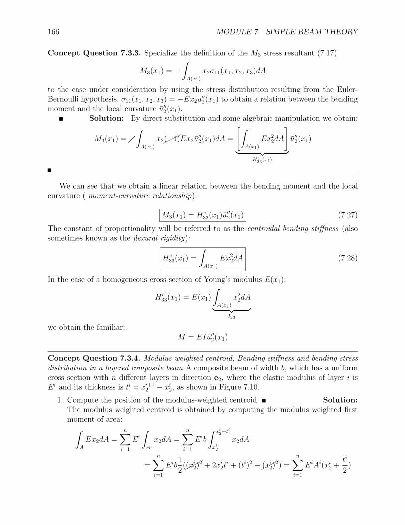
Concept Question 7.3.4. Modulus-weighted centroid, Bending stiffness and bending stressdistribution in a layered composite beam A composite beam of width b, which has a uniformcross section with n different layers in direction e2, where the elastic modulus of layer i isEi and its thickness is ti = xi+1
2 − xi2, as shown in Figure 7.10.
1. Compute the position of the modulus-weighted centroid Solution:The modulus weighted centroid is obtained by computing the modulus weighted firstmoment of area:∫
A
Ex2dA =n∑i=1
Ei
∫Aix2dA =
n∑i=1
Eib
∫ xi2+ti
xi2
x2dA
=n∑i=1
Eib1
2(��
�(xi2)2 + 2xi2ti + (ti)2 −��
�(xi2)2) =n∑i=1
EiAi(xi2 +ti
2)

7.3. BEAM BENDING 167
e2
−e3
xi2
xi+12
i = n, En
i, Ei
i = 1, E1
b
Figure 7.10: Cross section of a composite layered beam.
and dividing by the modulus weighted area (or axial stiffness):
S =
∫A
EdA =n∑i=1
EiAi
⇒ xc2 =
∑ni=1E
iAi(xi2 + ti
2)∑n
i=1 EiAi
2. Compute the bending stiffness Solution: From equation (7.28),
Hc33 =
∫A(x1)
E(x1, x2, x3)x22dA =
n∑i=1
∫Ai
Eix22dA
i =n∑i=1
Ei
∫Ai
x22dA
i
=n∑i=1
Eib1
3
[(xi+1
2
)3 −(xi2)3]
where care should be exercised to measure the distance x2 from the location of themodulus weighted centroid xc2.
3. Compute the σ11 stress distribution in the cross section assuming the bending moment
168 MODULE 7. SIMPLE BEAM THEORY
M3 is known: Solution: Recalling (7.26), we obtain:
σ11(x1, xi2 < x2 < xi+1
2 , x3) = Eiε11(x1, x2, x3) = −Eix2u′′2(x1) = −Eix2
M3
Hc33
4. Interpret the stress distribution obtained. Solution: The axialstrain distribution is linear over the cross section, this forces the stress distribution tobe piecewise linear within each layer of different elastic modulus, but discontinuous atinterlayer boundaries.
5. Specialize to the case that the section is homogeneous with Young’s modulus E:Solution: In this case, Hc
33 = EI33, and the previous equation becomes the familiarformula for simple beam theory:
σ11(x1, x2, x3) = −��Ex2M3
��EI33
,⇒ σ11(x1, x2, x3) = −x2M3(x1)
I33
(7.29)
Concept Question 7.3.5. Bi-material cross section properties
e2
e3
h2
h2
b
EA
EB
xc2
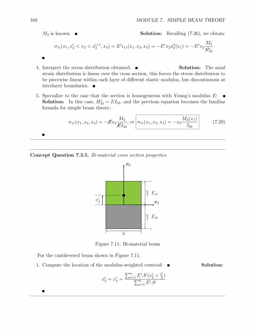
Figure 7.11: Bi-material beam
For the cantilevered beam shown in Figure 7.11,
1. Compute the location of the modulus-weighted centroid: Solution:
xc2 = xc2 =
∑ni=1E
iAi(xi2 + ti
2)∑n
i=1EiAi
7.3. BEAM BENDING 169
dx1
V2
M3
V2 +dV2dx1
dx1
M3 +dM3
dx1dx1
e1
e2
p2(x1)dx1
bcO
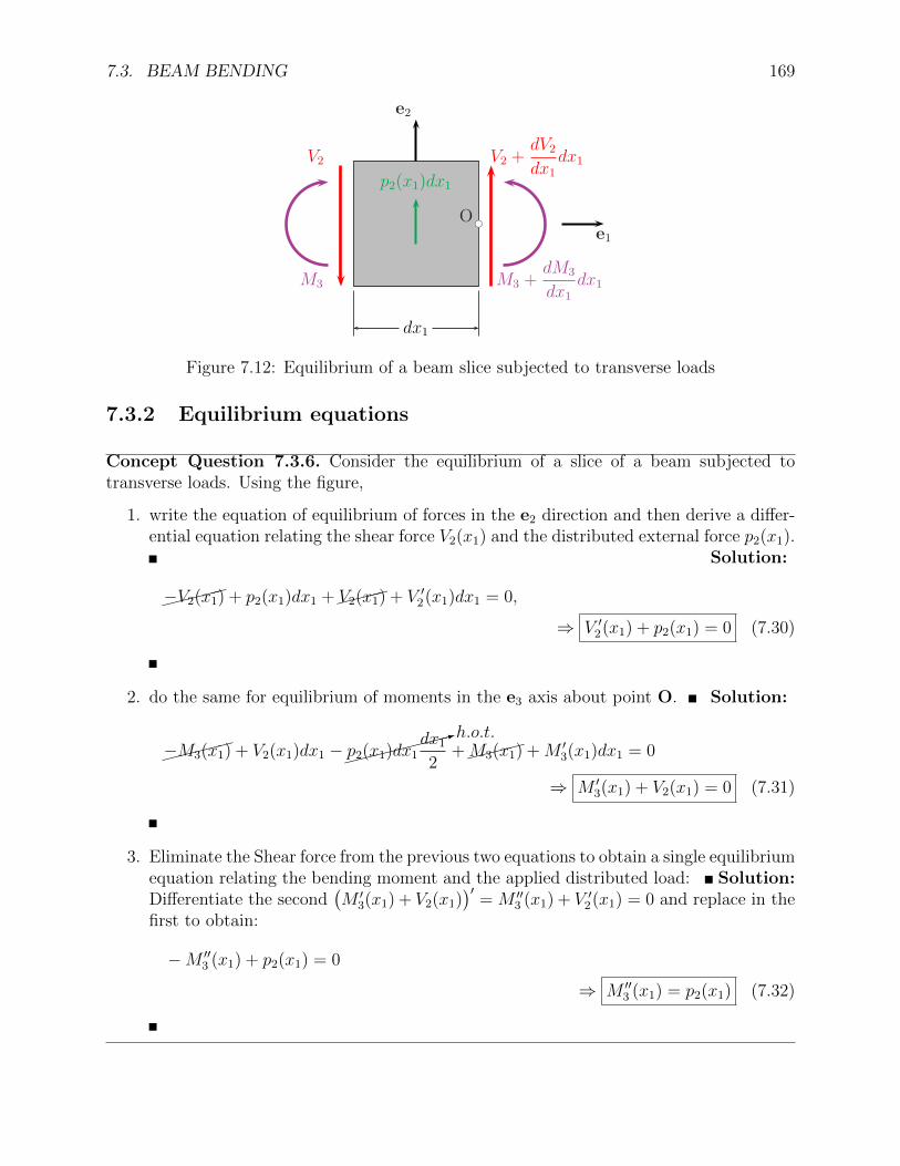
Figure 7.12: Equilibrium of a beam slice subjected to transverse loads
7.3.2 Equilibrium equations
Concept Question 7.3.6. Consider the equilibrium of a slice of a beam subjected totransverse loads. Using the figure,
1. write the equation of equilibrium of forces in the e2 direction and then derive a differ-ential equation relating the shear force V2(x1) and the distributed external force p2(x1).
Solution:
�����−V2(x1) + p2(x1)dx1 +���
�V2(x1) + V ′2(x1)dx1 = 0,
⇒ V ′2(x1) + p2(x1) = 0 (7.30)
2. do the same for equilibrium of moments in the e3 axis about point O. Solution:
�����−M3(x1) + V2(x1)dx1 −����
����:h.o.t.
p2(x1)dx1dx1
2+���
�M3(x1) +M ′3(x1)dx1 = 0
⇒ M ′3(x1) + V2(x1) = 0 (7.31)
3. Eliminate the Shear force from the previous two equations to obtain a single equilibriumequation relating the bending moment and the applied distributed load: Solution:Differentiate the second
(M ′
3(x1) + V2(x1))′
= M ′′3 (x1) + V ′2(x1) = 0 and replace in the
first to obtain:
−M ′′3 (x1) + p2(x1) = 0
⇒ M ′′3 (x1) = p2(x1) (7.32)
170 MODULE 7. SIMPLE BEAM THEORY
7.3.3 Governing equations
Concept Question 7.3.7. 1. Derive a governing differential equation for the transversely-loaded beam problem by combining Equations (7.27) and (7.32). Solution:(
H33(x1)u′′2(x1))′′
= p2(x1) (7.33)
2. What type of elasticity formulation does this equation correspond to? Solution:It corresponds to a displacement formulation and the equation obtained is a Navierequation.
3. What principles does it enforce? Solution: It enforces compatibility, theconstitutive law and equilibrium.
Concept Question 7.3.8. The equation requires four boundary conditions since it is afourth-order differential equation. Express the following typical boundary conditions math-ematically
1. clamped at one end Solution: this implies that the deflection and the rotationare restricted at that point
u2 = 0, u′2 = 0
2. simply supported or pinned Solution: this implies that the deflection is restrictedbut the the slope is arbitrary. The freedom to rotate implies that the support cannotsupport a bending moment reaction and M3 = 0 at that point
u2 = 0,M3 = Hc33u′′2 = 0, ⇒ u′′2 = 0
3. free (unloaded) Solution: implies that both the bending moment and the shearforce must vanish:
u′′2 = 0, V2 = −M ′3 = −(Hc
33u′′2)′ = 0
4. subjected to a concentrated transverse load P2 Solution: this implies that thatthe bending moment must vanish but the shear force must equal the applied load
u′′2 = 0, V2 = −M ′3 = −(Hc
33u′′2)′ = P2
7.3. BEAM BENDING 171
Concept Question 7.3.9. Cantilevered beam under uniformly distributed transverse loadA cantilevered beam (clamped at x1 = 0 and free at x1 = L) is subjected to a uniform
load per unit length p0.
1. Specialize the general beam equation to this problem Solution: The governingequation for u2(x1) reads
Hc33u
IV2 = p0
as the bending stiffness is constant.
2. Write down the boundary conditions for this problem:
Solution: At the clamped end x1 = 0, the transverse displacement and rotation ofthe section (slope of the beam) are both zeros, i.e.
u2(0) = u′2(0) = 0.
At the free end x1 = L, the bending moment and the shear force are zero, i.e.
Hc33u′′2(L) = 0, −Hc
33u′′′2 (L) = 0
3. Integrate the governing equation and apply the boundary conditions to obtain thedeflection u2(x1), bending moment M3(x1) and shear force V2(x1). Solution: Thegoverning equation can be integrated directly and the the following general expressionfor the deflection is obtained: After the first integration we get:
Hc33u′′′2 = p0x1 + c1 = −V2(x1)
After the secondHc
33u′′2 =
p0
2x2
1 + c1x1 + c2 = M3(x1)
After the thirdHc
33u′2 =
p0
6x3
1 +c1
2x2
1 + c2x1 + c3
After the last
Hc33u2(x1) =
1
24p0x
41 +
c1
6x3
1 +c2
2x2
1 + c3x1 + c4
The clamped boundary condition at x1 = 0 implies: u2(0) = c4 = 0, u′2(0) = c3 = 0.The free boundary condition at x1 = L implies: V2(L) = p0L + c1 = 0,⇒ c1 = −p0L,and M3(L) = p0
2L2 + (−p0L)︸ ︷︷ ︸
c1
L + c2 = 0,⇒ c2 = p02L2. Replacing in the expressions
above :
V2(x1) = p0L(1− x1
L
)
172 MODULE 7. SIMPLE BEAM THEORY
M3(x1) =p0
2x2
1 + (−p0L)︸ ︷︷ ︸c1
x1 +p0
2L2︸ ︷︷ ︸c2
=p0
2L2[1− 2
x1
L+(x1
L
)2]M3(x1) =
p0
2L2[1−
(x1
L
)]2
Hc33u2(x1) =
1
24p0x
41 +
c1︷ ︸︸ ︷(−p0L)
6x3
1 +
c2︷ ︸︸ ︷p0
2L2
2x2
1
u2(x1) =p0L
4
24Hc33
(x1
L
)2[(x1
L
)2 − 4(x1
L
)+ 6]
4. Compute the maximum deflection, maximum moment and maximum σ11 stress (forthe case of a solid rectangular wing spar of length L = 1m, width b = 5mm, heighth = 3cm, and Young’s modulus E = 100GPa when the load is p0 = 10N/m.Solution: In this case, the stiffness Hc
33 = EI = Ebh3
12= 200N · m2 and their
locations: The maximum deflection clearly occurs at the free end and takes the value
umax2 = u2(L) =p0L
4
8EI= 3.1cm.
The maximum moment clearly occurs at the root of the cantilever x1 = 0 and takesthe value:
Mmax3 = M3(L) =
p0
2L2 = 11.25N ·m.
The maximum stress can then be obtained from equation (7.29)
σmax11 = σ11(0,±h2, x3) = ∓h
2
M3(x1)
I33
= ∓56.25MPa
5. Give an expression for the spatial distribution of the stresses resulting from beamtheory Solution:
6. Compare this distribution with the solution obtained from 2D elasticity using the Airystress function approach and comment on the results. Are there any conditions underwhich the solutions match? What happens as the beams gets very short and very longrelative to the height? Solution: