module f: simple connections - i kuweb.iku.edu.tr/courses/insaat/ce636/simple connections.pdf ·...
TRANSCRIPT

CIE 428 Module F Instructor: Andrew Whittaker
8/21/2002 12:12 PM 1
MODULE F: SIMPLE CONNECTIONS
This module of CIE 428 covers the following subjects
Connector characterization
Failure modes of bolted shear connections
Detailing of bolted connections
Bolts: common and high-strength
Shear strength of high-strength bolts
Slip-critical connections
High-strength bolts in tension
Combined shear and tension in fasteners
Welded connections
Fillet welds
READING: Chapter 7 of Segui
AISC LRFD Manual of Steel Construction, 3rd Ed.

CIE 428 Module F Instructor: Andrew Whittaker
8/21/2002 12:12 PM 2
INTRODUCTION
For the purpose of this class, connections are characterized as either
Simple
Eccentric
The figure below from Segui illustrates different types of bolted and welded connections. Those connections in parts a and b of the figure are termed simple
Line of action of resultant force passes through the center of gravity of the connection
All parts of the connection share equally in resisting the load
The other connections are termed eccentric and are discussed in the following module. Eccentric connections are shown in parts c and d of the figure below.
Chapter J of the LRFD Specification addresses the design of connections. The following connectors are covered
Bolts
Rivets
Welds
Only bolted and welded connections are considered in CIE 428.

CIE 428 Module F Instructor: Andrew Whittaker
8/21/2002 12:12 PM 3
FAILURE MODES OF BOLTED SHEAR CONNECTIONS
Two types of bolted connector failure are considered in this section
Failure of the connector
Failure of the connected parts

CIE 428 Module F Instructor: Andrew Whittaker
8/21/2002 12:12 PM 4
Connector failure
Consider first the figure shown below from Segui that presents joints in single (one shear plane) and double (two shear planes) shear.
In part a of the figure (single shear connection), the load (shear) on the fastener is P and the connector failure is in the fastener.
Loading is not concentric on the fastener, the eccentricity is small and it will be ignored.
The load resisted by the fastener can be written as
vP f A=
where vf is the average shearing stress and A is the cross-sectional area.
In part b of the figure, the connector is in double shear and the load is equal to
2 vP f A=

CIE 428 Module F Instructor: Andrew Whittaker
8/21/2002 12:12 PM 5
Why?
Failure of the connected parts
The failure of the connected parts can be separated into two categories.
Failure resulting from excessive tension, shear, or bending in the parts being connected
For a tension member must consider tension on the net area, tension on the gross area, and block shear
For beam-beam or beam-column connections, must consider block shear
Gusset plates and framing angles must be checked for P, M, and V
Failure of the connected part because of bearing exerted by the fastener
If the hole is slightly larger than the fastener and the fastener is assumed to be placed loosely in the hole (rarely the case), contact between the fastener and the connected part will exist over approximately 50% of the circumference of the fastener. See the figure below for information.

CIE 428 Module F Instructor: Andrew Whittaker
8/21/2002 12:12 PM 6
The average bearing stress is
pPfdt
=
where terms are defined in the figure. If the maximum bearing pressure is known, the maximum load is easily calculated by manipulating the above equation
The bearing problem is complicated a little by the edge distance and bolt spacing; subjects that are discussed below. See the figure below from Segui for an illustration of these complications.

CIE 428 Module F Instructor: Andrew Whittaker
8/21/2002 12:12 PM 7
DETAILING BOLTED CONNECTIONS
Bearing strength, bolt spacing and bolt edge distance are considered in this section.
Bearing strength limits
One possible failure mode resulting from excessive bearing is shown in the figure below from Segui. In this figure, the actual failure surface is replaced by a failure surface in part b, which simplifies the calculation.
Noting the total failure load is equal to the sum of the failure loads on the two surfaces shown in part b of the figure:
2(0.6 ) 1.2n u c u cR F L t F L t= =
where

CIE 428 Module F Instructor: Andrew Whittaker
8/21/2002 12:12 PM 8
0.6 uF = Shear fracture stress of the connected part
cL = Distance from the edge of the hole to the edge of the connected part
t = Thickness of the connected part
The tear-out described above can also occur between bolt holes in the direction of the applied load as shown in the figure below, which provides an alternate definition for cL .
To prevent excessive elongation of the hole, an upper limit is placed on the bearing load. This limit is
( )n uR CF dt=
where
C = Constant
d = Bolt diameter
t = Thickness of the connected part
The values assigned to C are 2.4, 3.0, and 2.0, depending on the hole type and the acceptability of hole ovaling at service load. See Equations J3-2a, -2b, and –2c of the LRFD Specification for

CIE 428 Module F Instructor: Andrew Whittaker
8/21/2002 12:12 PM 9
details. Considering only standard (not slotted) holes, if excessive deformation is a concern, C = 2.4. In this case,
If 2 , 1.2c n c uL d R L tF≤ =
If 2 , 2.4c n uL d R dtF> =
The design bearing strength is equal to nRφ , where 0.75φ = .
Spacing and edge-distance requirements
Section J3.3 of the LRFD Specification sets a minimum center-to-center spacing (s) of bolts equal to 2.67d (and preferably not less than 3d), where d is the fastener diameter. Such distances are needed to maintain clearances between bolt nuts and maintain clearance for wrench sockets. See the figure from Segui below for details.
Section J3.4 of the LRFD Specification gives minimum edge distances ( eL ) as a function of bolt-size and type of edge (sheared, rolled, or gas cut). The table referenced in that section (Table J3.4) is presented below.

CIE 428 Module F Instructor: Andrew Whittaker
8/21/2002 12:12 PM 10
The example below from Segui illustrates the detailing requirements introduced above.

CIE 428 Module F Instructor: Andrew Whittaker
8/21/2002 12:12 PM 11

CIE 428 Module F Instructor: Andrew Whittaker
8/21/2002 12:12 PM 12
In the above example, the calculated bolt spacings and edge distances are the same in the gusset and tension member. Only the thickness will control in this case, and because the thickness of the tension member is less than that of the gusset, the gusset will control.
BOLTS: COMMON AND HIGH STRENGTH
Common bolts
Common bolts differ from high-strength bolts by
Material
Clamping force not accounted for with common bolts
Common bolts are designated as ASTM A307, with an ultimate shearing stress of 24 ksi (see Table J3.2 of the AISC LRFD Specification).
The design shear strength of A307 bolts is nRφ , where φ is 0.75, and the nominal shear strength is
24n v b bR F A A= =

CIE 428 Module F Instructor: Andrew Whittaker
8/21/2002 12:12 PM 13
where
vF = Ultimate shearing stress
bA = Cross-sectional area of the unthreaded part of the bolt (nominal bolt area)
t = Thickness of the connected part
CIE 428 Module F Instructor: Andrew Whittaker
8/21/2002 12:12 PM 14
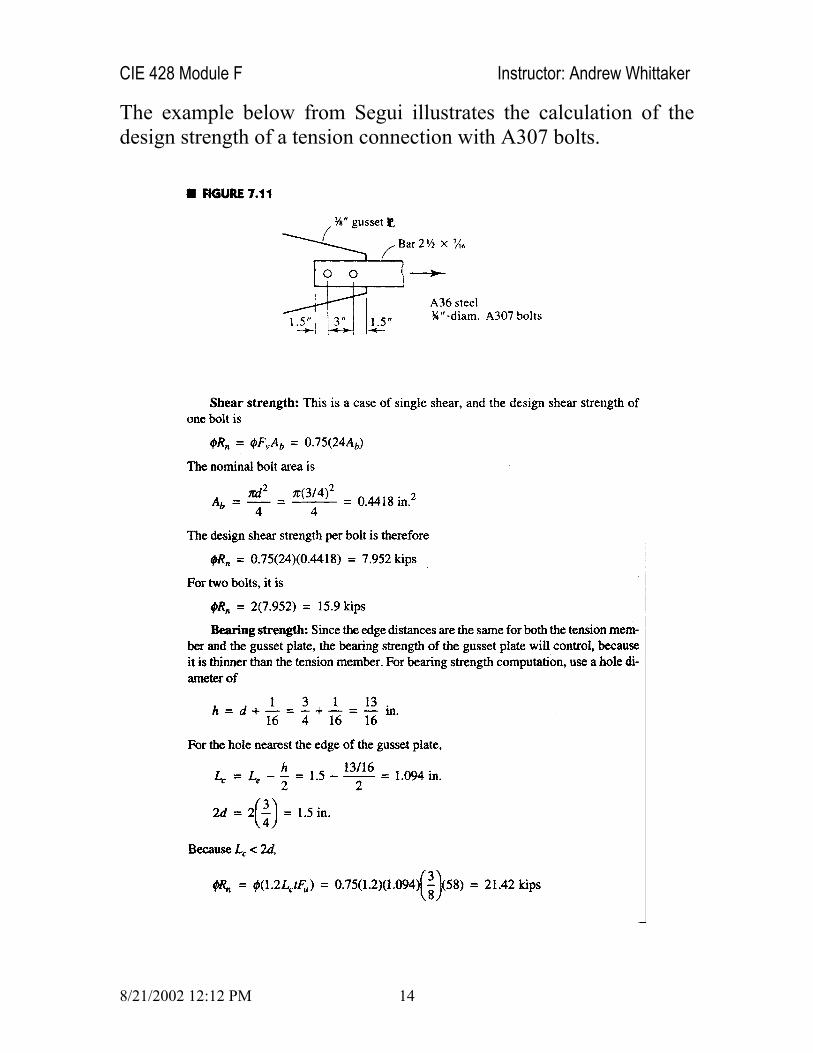
The example below from Segui illustrates the calculation of the design strength of a tension connection with A307 bolts.

CIE 428 Module F Instructor: Andrew Whittaker
8/21/2002 12:12 PM 15
High-strength bolts
High-strength bolts for structural joints come in two grades, namely
ASTM A325
ASTM A490
Two conditions of bolt installation are used with high-strength bolts
Snug-tight (producing a bearing connection)
Few impacts of an impact wrench
Full effort of a worker with an ordinary spud wrench

CIE 428 Module F Instructor: Andrew Whittaker
8/21/2002 12:12 PM 16
Tensioned (producing a slip-critical connection)
Turn-of-nut method: specified number of rotations of the nut from snug tight (nut rotations correlated to bolt elongation)
Calibrated wrench tightening
Alternate design bolts: specially design bolts whose tops twist off when the proper tension has been achieved
Direct tension indicators: compress washer (under bolt head or nut) with protrusions to a gap that is correlated to bolt tension

CIE 428 Module F Instructor: Andrew Whittaker
8/21/2002 12:12 PM 17
When high-strength bolts are to be tensioned, minimum limits are set on the bolt tension. See Table J3.1 in the LRFD Specification.
Tension equal to 70% of the minimum tensile strength of the bolt
Purpose of tensioning is to achieve the clamping force shown in the figure below from Segui

CIE 428 Module F Instructor: Andrew Whittaker
8/21/2002 12:12 PM 18
In reference to the figure above, as the bolt is tensioned and elongates, the connected parts undergo compression. The total compressive force on the parts is equal to the bolt tension.
If an external force P is applied, a friction force will develop between the connected parts, with a maximum value of
F Nµ=
where µ is the coefficient of static friction between the connected parts (a function of surface condition of the steel parts) and N is the normal force shown in the figure above.
Each bolt in the connection is then capable of resisting a force P = F before slippage. Prior to slippage, there is no bearing or shear.
SHEAR STRENGTH OF HIGH-STRENGTH BOLTS
The design shear strength of high strength bolts, like A307 bolts, is nRφ , where φ is 0.75. Unlike A307 bolts, the shear strength of
A325 and A490 bolts depends on whether the threads are in the shear plane (threads not excluded from the shear plane) or not (threads excluded from the shear plane).
A325-N: threads included in the shear plane
A325-X: threads excluded from the shear plane
Rather than using a reduced cross-sectional area when the threads are not excluded from the shear plane, the ultimate shear stress is multiplied by a factor of 0.75 in the LRFD Specification. Results are presented in the last column of Table J3.2 of the Specification, which was reproduced above. In summary,

CIE 428 Module F Instructor: Andrew Whittaker
8/21/2002 12:12 PM 19
Fastener Threads n v bR F A=
A325 Included in shear plane 48 bA
A325 Excluded from shear plane 60 bA
A490 Included in shear plane 60 bA
A490 Excluded from shear plane 75 bA
The calculation of the design strength of a connection is illustrated below. The bolts are 7/8 inch in diameter; threads are not in the shear plane, and the steel is Grade 50 steel.

CIE 428 Module F Instructor: Andrew Whittaker
8/21/2002 12:12 PM 20

CIE 428 Module F Instructor: Andrew Whittaker
8/21/2002 12:12 PM 21
SLIP-CRITICAL CONNECTIONS
As noted earlier, a connection with high-strength bolts is classified as either a bearing or slip-critical connection.
In bearing connections, the bolt is brought to a snug-tight condition so that the surfaces of the connected parts are in firm contact.
Slippage is acceptable
Shear and bearing on the connector
In slip-critical connections, no slippage is permitted and the friction force described earlier must not be exceeded.
Slippage is not acceptable
Slip-critical strength based on factored loads herein. The LRFD Specification writes rules for basing the strength on service loads but such an approach is not discussed in CIE 428. Refer to the Specification for details.
Proper installation and tensioning is key
Connector not subjected to shear and bearing (in theory)

CIE 428 Module F Instructor: Andrew Whittaker
8/21/2002 12:12 PM 22
Must have sufficient shear and bearing strength in the event of overload that causes slip. See Section J3.8 of the LRFD Specification for details.
AISC writes that slip-critical bolted (or welded) connections be used in specific circumstances. Part of Section J1.11 of the LRFD Specification that lists these circumstances is reproduced below.
As introduced earlier, the resistance to slip is a function of the product of the
Normal force (equal to the bolt tension)
Coefficient of static friction between the contact surfaces
The LRFD Specification writes that the design slip resistance per bolt, strrφ , shall equal or exceed the required force due to factored loads, where
1.13str b sr T Nµ=

CIE 428 Module F Instructor: Andrew Whittaker
8/21/2002 12:12 PM 23
where 1.13 is a factor that accounts for the expected 13% increase above the minimum specified preload provided by calibrated torque wrench tightening procedures, and
µ = Mean slip coefficient of friction for Class A, B, or C surfaces
bT = Minimum fastener tension (see Table J3.1 of the Specification)
sN = Number of slip planes (described earlier)
Guidance is provided for the mean slip coefficient (static coefficient of friction) associated with the three classes of surface noted above.
For unpainted clean mill scale steel surfaces (Class A), 0.33µ =
Assumed surface for CIE 428 u.n.o.
For unpainted blast-cleaned steel surfaces (Class B), 0.50µ =
For hot-dip galvanized and roughened steel surfaces (Class C), 0.35µ =
The resistance factor varies as a function of the type of hole and its orientation. The LRFD Specification writes that
For standard holes, 1.0φ =
Assumed hole geometry for CIE 428 u.n.o.

CIE 428 Module F Instructor: Andrew Whittaker
8/21/2002 12:12 PM 24
For oversized and short-slotted holes, 0.85φ =
For long-slotted holes transverse to the direction of load, 0.70φ =
For long-slotted holes parallel to the direction of load, 0.60φ =
The two examples from Segui below illustrate aspects of the checking or design of high-strength, slip-critical bolted connections.

CIE 428 Module F Instructor: Andrew Whittaker
8/21/2002 12:12 PM 25

CIE 428 Module F Instructor: Andrew Whittaker
8/21/2002 12:12 PM 26
The following example presents a design procedure for slip-critical connections. The C6x13 shown below is to resist a factored load of 108 kips. Bolts to be used are 7/8-inch diameter, A325; threads are in the shear plane and slip of the connection is permitted. Determine the number and layout of bolts so that h is a minimum. A36 steel is used.

CIE 428 Module F Instructor: Andrew Whittaker
8/21/2002 12:12 PM 27

CIE 428 Module F Instructor: Andrew Whittaker
8/21/2002 12:12 PM 28

CIE 428 Module F Instructor: Andrew Whittaker
8/21/2002 12:12 PM 29

CIE 428 Module F Instructor: Andrew Whittaker
8/21/2002 12:12 PM 30
Based on the above example, what are the steps in the design of a slip-critical connection?
Below is an example from Segui of the design of a tension member and its connection. This example is an extension of the last example where the size of the tension member was given. In the example below, the tension member must also be sized, based in part on the connection details.
Is this an appropriate consideration for design?

CIE 428 Module F Instructor: Andrew Whittaker
8/21/2002 12:12 PM 31

CIE 428 Module F Instructor: Andrew Whittaker
8/21/2002 12:12 PM 32

CIE 428 Module F Instructor: Andrew Whittaker
8/21/2002 12:12 PM 33

CIE 428 Module F Instructor: Andrew Whittaker
8/21/2002 12:12 PM 34

CIE 428 Module F Instructor: Andrew Whittaker
8/21/2002 12:12 PM 35

CIE 428 Module F Instructor: Andrew Whittaker
8/21/2002 12:12 PM 36
HIGH-STRENGTH BOLTS IN TENSION
When a tensile force Q is applied to a non-tensioned (snug-tight) bolt, the resulting tensile force in the bolt is equal to the applied tensile force, Q.
When a tensile force Q is applied to a tensioned bolt with pre-tension 0T , the resulting tensile force in the bolt is approximately equal to 0T , where the applied force relieves the compression (clamping forces) on the connected parts.
An example of a high-strength bolt in tension is shown below (from Segui). Consider now the circled bolt in tension.

CIE 428 Module F Instructor: Andrew Whittaker
8/21/2002 12:12 PM 37
Consider the bolt and the connected part shown in the figure below from Segui. Part a of the figure shows free-body diagrams of the parts after tensioning. Note that the bolt and the connected part are in equilibrium.
Shown in part a of the figure is the bolt tension 0T and the normal clamping force 0N (equal in magnitude to 0T ).

CIE 428 Module F Instructor: Andrew Whittaker
8/21/2002 12:12 PM 38
When an external tensile force F is applied (to one bolt), the forces are those shown in part b of the figure above. Summing the forces in part c of the figure gives the total tensile force in the bolt as
T F N= +
The application of the force F will increase the bolt tension and cause it to elongate by an amount bδ . Compression in the flange of the structural tee (assumed connection detail) will be reduced, resulting in a distortion flδ in the same sense as bδ . Assuming that the clamping force N is applied over a uniform area of flange flA , and that the connected parts (the flanges) do not separate
( )fl fl fl flb b b bb
b fl b fl
A E AA E AF T N EL L L L
δδ δ∆ = ∆ − ∆ = − = −
where bL is the length of the bolt (in tension) and flL is the thickness of the flange. Note that these lengths are of the same order and that flA is much greater than bA :
N T∆ ∆ and F N∆ ≈ ∆
The ratio of T∆ to N∆ is approximately 0.05 to 0.10.
Most of the applied load relieves the compression on the connected parts.
To estimate the magnitude of the applied load required to overcome the clamping effect (for the parts to separate), consider the figure below from Segui.

CIE 428 Module F Instructor: Andrew Whittaker
8/21/2002 12:12 PM 39
For the connected parts to separate, the change in the compressive force must equal the initial pre-compression, namely, 0N N∆ = . When the parts have separated,
0 0 0 0 00.1 0.1 1.1F T T T N T N T= + ∆ = + ∆ = + =
That is, at the point of separation, the bolt tension is approximately 10% larger than the pretension.
What happens once the parts have separated?
Any increase in external load F will be resisted entirely by an increase in bolt tension.
To avoid separation (and use the design strengths given in Table J3.2 of the LRFD Specification), high-strength bolts subject to direct tension must be pretensioned to the values given in Table J3.1, regardless of whether the connection is slip-critical or not.
Calculate the tension force in the bolt assuming that there is no initial tension.
Prying Action
In connections in which the fasteners are subjected to tension forces, the flexibility of the connected parts can lead to deformations that increase the tensile force applied to the fastener.

CIE 428 Module F Instructor: Andrew Whittaker
8/21/2002 12:12 PM 40
Force is known as prying force
Shown in the figure below from Segui
Before the external load is applied, the normal compressive force
0N is centered on the bolt. As the external load is applied and if the flange is sufficiently flexible to deform as shown above, the compressive forces will migrate towards the edges of the flanges. This redistribution will change the relationship between all of the forces and the bolt tension will increase.
If the flange is rigid, no redistribution will occur.
How stiff is rigid in this case?
The maximum prying force will be reached when only the corners of the flange remain in contact with the connected part. See the figure above for details.

CIE 428 Module F Instructor: Andrew Whittaker
8/21/2002 12:12 PM 41
For connections of the type shown above, Section J3.6 of the LRFD Specification writes that the applied load shall be the sum of the factored loads and any tension resulting from prying action produced by deformation of the connected parts.
A procedure for determining prying forces is given in Part 9 of the LRFD Specification. The presentation of Segui is similar and gives identical results. Consider the part of a structural tee shape shown below. The presentation is for one fastener only. The force T is the external factored tension force applied to one bolt, Q is the prying force applied to one bolt, and cB is the total bolt force. The prying force has shifted to the tip of the flange of the tee and is at its maximum value.

CIE 428 Module F Instructor: Andrew Whittaker
8/21/2002 12:12 PM 42
From consideration of force and moment equilibrium, the following equations are derived:
; ;a a b b cTb M Qa M Qa B T Q− −− = = = +
These equations can be combined into a single equation for the bolt force, including the effects of prying. First, a variable is defined as the ratio of the moment per unit length along the bolt line to the moment per unit length at the face of the stem
b b
a a
MM
αδ
−
−
=
where
δ = Net area at bolt line divided by gross area at stem = 1 /d p′−
d ′ = Diameter of the bolt hole
p = Length of flange tributary to one bolt
a aM − = Design strength at a-a = 2( / 4)b f ypt Fφ
The total bolt force cB can thus be calculated as
[1 ](1 )c
bB Ta
δαδα
= ++
At this level of loading, the resultant of the tensile force in the bolt does not coincide with the axis of the bolt. For better agreement with test results, the force resultant is shifted toward the stem of the tee by d/2, where d is the bolt diameter, that is

CIE 428 Module F Instructor: Andrew Whittaker
8/21/2002 12:12 PM 43
0.5 ; 0.5b b d a a d′ ′= − = +
and
[1 ](1 )c
bB Ta
δαδα
′= +
′+
If the bolt force cB is set equal to the design tensile strength, denoted B,
[( / ) 1]( / ){1 [ / ) 1]( / )}
B T a bB T a b
αδ
′ ′−=′ ′− −
Two limit states are possible
Tensile failure of the bolt
Bending failure of the tee
Plastic moments form at lines a-a and b-b producing a mechanism
If the absolute value of α is less than 1.0, the moment at the bolt line per unit length is less than that at the face of the stem, indicating that the mechanism has not formed
Tensile failure of the bolt controls, and cB B=
If the absolute value of α is greater than or equal to 1.0, plastic hinges will have formed at both a-a and b-b
Controlling limit state is bending failure of the tee

CIE 428 Module F Instructor: Andrew Whittaker
8/21/2002 12:12 PM 44
Since the moments at a-a and b-b are limited to the plastic moment, α should be set equal to 1.0.
The three equilibrium equations presented at the top of page 42 can be combined into a single equation to establish the required flange thickness, ft , as follows:
2
( ) ( )4
a a b b
a a
f yb p b
Tb M M
M
pt FM
δα
δα φ δα φ
− −
−
′ − =
=
= =
and for 0.90bφ = ,
4.444(1 )f
y
TbtpF δα
′=
+
The design of connections subjected to prying forces involves iteration.
Always make an allowance for prying force in design
Select a trial thickness and bolt geometry
Calculate ft and cB using the above equations
If actual ft is different from the required value, the actual values of α and cB will be different from those previously calculated

CIE 428 Module F Instructor: Andrew Whittaker
8/21/2002 12:12 PM 45
If the actual bolt force, which includes the prying force, is desired, α must be recomputed. Using b′ instead of b, and setting
a a b pM Mφ− = , then
21 4.444( 1)
f y
Tbpt F
αδ
′= −
The total bolt force can now be found using the boxed equation on page 43.
What if the flange thickness is inadequate?
Increase the flange thickness by using another tee shape
Use more bolts to reduce T
The example below from Segui illustrates most of the concepts introduced above.

CIE 428 Module F Instructor: Andrew Whittaker
8/21/2002 12:12 PM 46

CIE 428 Module F Instructor: Andrew Whittaker
8/21/2002 12:12 PM 47

CIE 428 Module F Instructor: Andrew Whittaker
8/21/2002 12:12 PM 48
COMBINED SHEAR AND TENSION IN FASTENERS
Most connections involving simultaneous shear and tension are eccentric connections, which will be discussed in the next module. One exception is the connection shown below, where, because the line of action passes through the center of gravity of the connection, each fastener can be assumed to resist an equal share of each component (V and T) of the load.
An elliptical interaction curve is used for the case of combined loading in bearing-type connections, as shown in the figure below.
The equation for this curve is given by the following equation
2 2[ ] [ ] 1.0( ) ( )
u u
n t n v
T VR Rφ φ
+ =
where

CIE 428 Module F Instructor: Andrew Whittaker
8/21/2002 12:12 PM 49
uT = Factored tensile load on the bolt
( )n tRφ = Design strength of the bolt in tension
uV = Factored tensile load on the bolt
( )n vRφ = Design strength of the bolt in shear
For performance checking, the above equation is written as
2 2[ ] [ ] 1.0( ) ( )
u u
n t n v
T VR Rφ φ
+ ≤
This equation can be re-packaged to permit calculation of the required bolt area in a connection as follows
2 2( ) ( )u ub
t v
T VAF Fφ φ
≥ +∑
The 3rd Ed of the LRFD presents the interaction equations in two forms. The interaction equations are listed in Table A-J3.1 of the Specification. The body of the specification uses a different format and parses the elliptical interaction curve into three straight-line segments as shown in the figure below from the Specification.

CIE 428 Module F Instructor: Andrew Whittaker
8/21/2002 12:12 PM 50
The Specification writes that in combined shear and tension in a bearing type connection, the design strength of the bolt is given by
t bF Aφ
where
tF =
Nominal tension stress computed using the equations in Table J3.5 of the LRFD Specification (see below) as a function of the shear stress produced by the factored loads. Note that the design shear strength, vFφ , must equal or exceed the shear stress vf .
bA = Nominal unthreaded body area of the bolt
φ = 0.75
For slip-critical connections in which the bolts are subjected to shear and tension, the effect of the applied tensile force is to reduce the clamping force, thereby reducing the allowable friction force.

CIE 428 Module F Instructor: Andrew Whittaker
8/21/2002 12:12 PM 51
The LRFD Specification reduces the slip-critical shear strength in this case by multiplying the slip-critical shear strength ( strrφ ) by
[1 ]1.13
u
m b
TT N
−
where
uT = Factored tensile load on the bolt
mT = Prescribed initial bolt tension
bN = Number of bolts in the connection
The uses of some of the above design equations are illustrated below using an example from Segui.

CIE 428 Module F Instructor: Andrew Whittaker
8/21/2002 12:12 PM 52

CIE 428 Module F Instructor: Andrew Whittaker
8/21/2002 12:12 PM 53
WELDED CONNECTIONS
Structural welding is a process whereby the parts to be connected are heated and fused with a molten filler metal. The figure below from Segui illustrates two fillet-welded connections.

CIE 428 Module F Instructor: Andrew Whittaker
8/21/2002 12:12 PM 54
Upon cooling, the structural steel (parent metal) and weld or filler metal will act as one continuous part. The filler metal is deposited from a special electrode. A number of welding processes are used, depending on the application
Field welds
Shop welds
Shown below is a figure from Segui that illustrates shielded metal arc welding (SMAW):
Current arcs across the gap between the electrode and the base metal
Connected parts are heated and part of the filler metal is deposited into the molten base metal
Coating on the electrode vaporizes and forms a protective gaseous shield, preventing the molten metal from oxidizing before it solidifies

CIE 428 Module F Instructor: Andrew Whittaker
8/21/2002 12:12 PM 55
The electrode is moved across the joint and a weld bead is deposited
Size of the weld bead depends on the rate of travel
As the weld cools, impurities rise to the surface and form a coating called slag
Slag must be removed before the next pass or the weld is painted
Shielded metal arc welding is normally done manually and is widely used for field welding
Self-shielded flux core
Gas shielded flux core
These and other processes are used for shop welding. Shop processes are automated or semi-automated in many cases. Other processes include
Submerged arc welding: end of the electrode and the arc are submerged in a granular flux that melts and forms a gaseous shield.
Electroslag
As noted earlier, the two common types of welds are
Fillet welds
Welds placed in a corner formed by two parts in contact
See figure on page 54

CIE 428 Module F Instructor: Andrew Whittaker
8/21/2002 12:12 PM 56
Groove welds
Welds deposited in a gap between two parts; see figure below
Single bevel groove welds shown in the figure
Backing bar
One of both of the parts must be prepared
Plug welds are shown in the figure below from Segui
Circular or slotted hole that is filled with weld metal
Used sometimes when more weld length is needed than is available

CIE 428 Module F Instructor: Andrew Whittaker
8/21/2002 12:12 PM 57
Panel zone doubler plates of seismic moment frames
Of the two key types of welds, fillet welds are the most common and are considered in the following section. Fillet welds are cheaper than groove welds.
Why?
The design of complete joint penetration (CJP) groove welds is generally straightforward. The filler metal is equally or overmatched to the parent metal (equal strength or greater)
Connected parts considered continuous through the weld
FILLET WELDS
The design and analysis of fillet welds is based on the assumption that the geometry of the weld is a 45-degree right triangle as shown below in the figure from Segui.
Shown in the above figure are the leg length (w) and the throat thickness (t).

CIE 428 Module F Instructor: Andrew Whittaker
8/21/2002 12:12 PM 58
Standard weld sizes are expressed in sixteenths of an inch.
Failure of fillet welds is assumed to occur in shear on the throat. That failure plane is also shown in the figure above.
The strength of a fillet weld depends on the strength of the filler or electrode metal used. The strength of an electrode is given in terms of its tensile strength in ksi. Strengths of 60, 70, 80, 90, 100, 110, and 120 ksi are available.
The standard notation for an electrode is E**XX where ** indicate the tensile strength in ksi and XX denotes the type of coating used.
Usually XX is the focus of design
E70XX is an electrode with a tensile strength of 70 ksi
Electrodes should be chosen to match the base metal.
Use E70XX electrodes for use with steels that have a yield stress less than 60 ksi
Use E80XX electrodes that have a yield stress of 60 ksi or 65 ksi
The critical shearing stress on a weld of length L is given by
0.707vPf
wL=
where all terms are defined above. If the ultimate shearing stress in the weld is termed WF , the nominal design strength of the weld can be written as

CIE 428 Module F Instructor: Andrew Whittaker
8/21/2002 12:12 PM 59
0.707 ( ) 0.707 (0.75[0.6 ]) 0.32n w EXX EXXR wL F wL F wLFφ φ= = =
For E70XX and E80XX electrodes, the design stresses are WFφ , or 31.5 ksi and 36 ksi, respectively.
In addition, the factored load shear on the base metal shall not produce a stress in excess of BMFφ , where BMF is the nominal shear strength of the connected material. The factored load on the connection is thus subjected to the limit of
0.90(0.6 ) 0.54n BM g y g y gR F A F A F Aφ φ= = =
where gA is the area subjected to shear. When the load is in the same direction as the axis of the weld, such as that shown in the figure below from Segui, the base metal must also be examined using the above equation.
Putting aside the eccentricity of the connection, the design strength of the welds (2 in total) is 2(0.707 )Ww Fφ and the shear capacity of the bracket is BMt Fφ .
The following table from the LRFD Specification presents the design strength of welds. The example on the page following the table, from Segui, illustrates the design approaches presented above.

CIE 428 Module F Instructor: Andrew Whittaker
8/21/2002 12:12 PM 60

CIE 428 Module F Instructor: Andrew Whittaker
8/21/2002 12:12 PM 61

CIE 428 Module F Instructor: Andrew Whittaker
8/21/2002 12:12 PM 62
Practical detailing of welded connections requires a consideration of minimum weld size, maximum weld size, and length.
The minimum size of a fillet weld is a function of the thickness of the thicker connected part. See Table J2.4 from the LRFD Specification, reproduced below, for details.
The maximum size of a fillet weld is as follows
Along the edge of a connected part less than ¼-inch thick, the maximum fillet weld size (w) equals the plate thickness
For other values of plate thickness, t, the maximum weld size is 1/16t − in.
The minimum permissible length of a fillet weld is 4 times its size. If only a shorter length is available, / 4w L= . For the welds in the connection shown below, L W≥ to address shear lag in such connections.

CIE 428 Module F Instructor: Andrew Whittaker
8/21/2002 12:12 PM 63
When a weld extends to the corner of a member, it must be continued around the corner (an end return) as shown in the figure below from Segui.
Prevent stress concentrations at the corner of the weld
Minimum length of return is 2w
Welds are shown on structural drawings by standard symbols. Some standard symbols are shown below in a figure from Segui. Symbols from the LRFD Specification are shown on the next page.
Near side, far side, weld size, weld length

CIE 428 Module F Instructor: Andrew Whittaker
8/21/2002 12:12 PM 64

CIE 428 Module F Instructor: Andrew Whittaker
8/21/2002 12:12 PM 65
Below is an example from Segui that illustrates some of the concepts introduced above.

CIE 428 Module F Instructor: Andrew Whittaker
8/21/2002 12:12 PM 66
- END OF MODULE -