module 7 relation between field theory and circuit theory
TRANSCRIPT
1
Electronic Science Electrodynamics and Microwaves
7. Relation between Circuit and Field Theory and Circuit Theory
Module 7
Relation between Field Theory and Circuit Theory
1. Introduction
2. Basics of circuit and Field theory
3. Ohms law
4. Kirchhoff’s Laws
5. Inductance and Capacitance
6. LCR series circuit
7. Lumped and Distributed Component model
8. Transmission line Equations
9. Wave guides, Cavity Resonators and Antenna
10. Magnetic circuits
11. Numerical and Graphical techniques
12. Summary
Learning outcome
After going through the contents of this module, you will be able to understand
1. The derivations of basic circuit laws and equations using EM Field theory and underlying
assumptions
2. The role of Mathematical Theorems and numerical technique.
3. The concept of lumped and distributed parameters.
4. The analogy between electrical and magnetic Circuit.
2
Electronic Science Electrodynamics and Microwaves
7. Relation between Circuit and Field Theory and Circuit Theory
1. Introduction
In this module, let us discuss mainly how circuit theory and field theory are related with each
other. The basic laws namely Ohms law and Kirchhoff‟s laws of circuit theory can be derived
using the field theory. Some results of field theory and Maxwell‟s equations play an importa nt
role in this regards. Some systems like transmission lines can be discussed using circuit theory as
well as field theory under some assumptions?
As against to it, systems like waveguides can be dealt with only using field theory. We can
analyze magnetic circuits using their analogy with electrical circuits. Numerical methods can
play an important role of a bridge connecting circuit theory and field theory. In this module, let
us discuss mainly about “how and why?” part related with these and some othe r topics.
2. Basics of circuit and Field theory
To begin with let us see some basic facts about the two theories. We know that, in circuit theory,
besides energy sources, we always have to think about three components namely resistor,
capacitor and inductor. The reason is obvious.
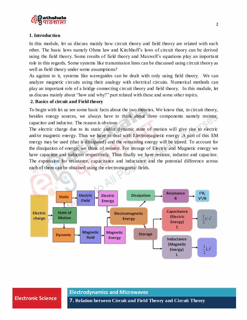
The electric charge due to its static and/or dynamic state of motion will give rise to electric
and/or magnetic energy. Thus we have to deal with Electromagnetic energy .A part of this EM
energy may be used (that is dissipated) and the remaining energy will be stored. To account for
the dissipation of energy, we think of resistor. For storage of Electric and Magnetic energy we
have capacitor and inductor respectively. Thus finally we have resistor, inductor and capacitor.
The expression for resistance, capacitance and inductance and the potential difference across
each of them can be obtained using the electromagnetic fields.
3
Electronic Science Electrodynamics and Microwaves
7. Relation between Circuit and Field Theory and Circuit Theory
Ohms Law and Kirchhoff‟s laws are the main laws which form the basis of Circuit theory and
can be derived using field theory. The circuit variables namely potential difference V across and
the current I through a conductor are related with the electromagnetic fields as shown.
The Electromagnetic field theory mainly involves Lorentz force and Maxwell‟s Equations along
with different laws of electromagnetics associated with them as shown.
t
DJH
t
BE
0B
ρD
In field theory we have to think of Maxwell‟s equation and Lorentz force in association with
each other. This is because from Maxwell‟s equations, we come to know how fields behave. The
relation of force with the EM fields is known from Lorentz force. Thus through Lorentz force
Maxwell‟s equations tell us how electric and magnetic fields interact with matter. The quantities
like resistance, capacitance, and inductance can then be expressed in terms of the lectromagnetic
properties of the matter.
Lorentz force
BVqEq F
In circuit theory, we use sources of electrical energy, say a chemical cell, for example. The
concepts of field theory in terms of the quantities like ion density, mobility, concentration
gradient, diffusion coefficient of positive and negative ions etc are to be used while theoretically
estimating the emf receivable from the cell. In circuit theory, it is not expected to obtain such
expressions. We assume the values of emf to be known.
Now, as a part of discussion about relation between the field and circuit theory, let us discuss one
by one, how various laws and some results used in circuit theory can be derived using Field
theory, in more general form. To start with let us discuss about Ohms law.
ldHI
ldEV
C
b
a
4
Electronic Science Electrodynamics and Microwaves
7. Relation between Circuit and Field Theory and Circuit Theory
3. Ohms law
We all are familiar with the statement and meaning of the physical quantities involved in the
mathematical expression representing ohm‟s law which are as given below.
Statement: Physical conditions of the conductor remaining same , the potential difference
across the conductor is directly proportional to the electric current flowing through it.
Mathematical Expression: V = IR
V- Potential difference across the conductor.
I- Current flowing through the conductor.
R- Resistance offered by the conductor to electric current.
Derivation of Ohm’s law
Linear or piece wise linear circuits and systems can be analyzed using Ohm‟s law. Can Ohms
law be derived from Maxwell‟s equation alone? Unfortunately the answer is negative. However,
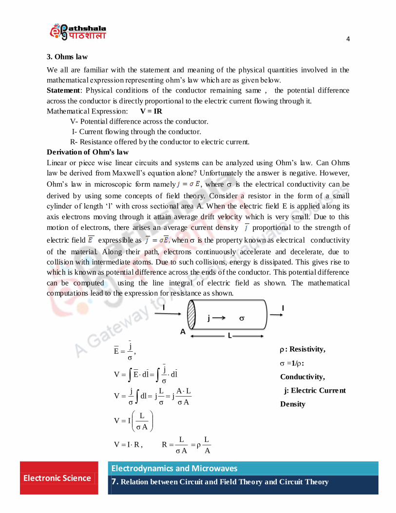
Ohm‟s law in microscopic form namely , where is the electrical conductivity can be
derived by using some concepts of field theory. Consider a resistor in the form of a small
cylinder of length „l‟ with cross sectional area A. When the electric field E is applied along its
axis electrons moving through it attain average drift velocity which is very small. Due to this
motion of electrons, there arises an average current density proportional to the strength of
electric field expressible as when is the property known as electrical conductivity
of the material. Along their path, electrons continuously accelerate and decelerate, due to
collision with intermediate atoms. Due to such collisions, energy is dissipated. This gives rise to
which is known as potential difference across the ends of the conductor. This potential difference
can be computed using the line integral of electric field as shown. The mathematical
computations lead to the expression for resistance as shown.
: Resistivity,
=1/:
Conductivity,
j: Electric Current
Density
A
Lρ
Aσ
LR,RIV
Aσ
LIV
Aσ
LAj
σ
Ljdl
σ
jV
ldσ
jldEV
,σ
jE
5
Electronic Science Electrodynamics and Microwaves
7. Relation between Circuit and Field Theory and Circuit Theory
From the expression for resistance, we understand that resistance of a resistor is directly
proportional to its length and inversely proportional to the area of cross section. This is a result
familiar to us. It be noted that, the result is derived separately using the concept in
field theory and is known as Ohm‟s Law in Microscopic (Point) form.
Drude’s Model: Ohm‟s law in microscopic form namely , can be derived by using some
other models also. It is advisable to refer to one of such model known in literature as “Drude‟s
Model”. It uses the concept of drift velocity of charged particles and some other quantities. For
small electric fields, using the linear response theory, ohms law in microscopic form can be
derived. It leads to Kubo‟s formula for electrical conductivity which involves the use of
Maxwell‟s equations as one of the many entities. O ne should remember the rigor in
mathematical and theoretical considerations in establishing this apparently simple law.
4. Kirchhoff’s Laws
Kirchhoff’s current Law (KCL)
Now, let us see how Kirchhoff‟s first law known as Kirchhoff‟s current Law can be derived
using the results of field theory.
Statement: The algebraic sum of the currents at a node is zero.
Mathematical Form:
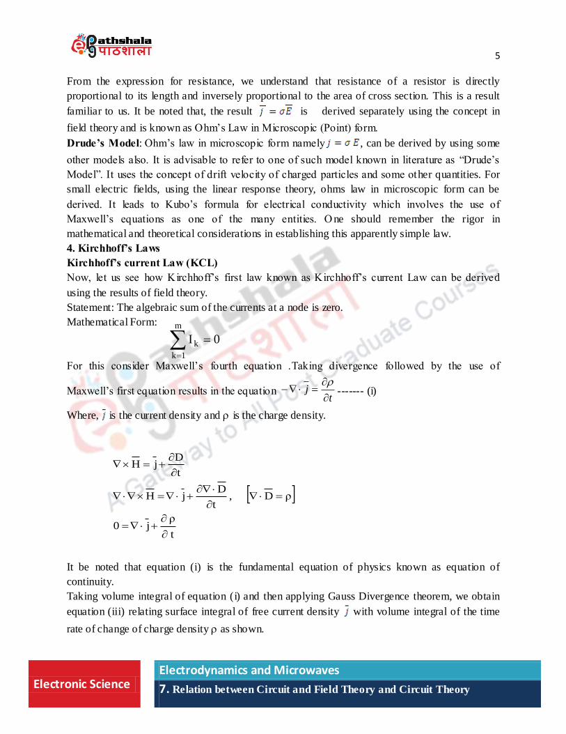
For this consider Maxwell‟s fourth equation .Taking divergence followed by the use of
Maxwell‟s first equation results in the equation t
j
------- (i)
Where, is the current density and is the charge density.
It be noted that equation (i) is the fundamental equation of physics known as equation of
continuity.
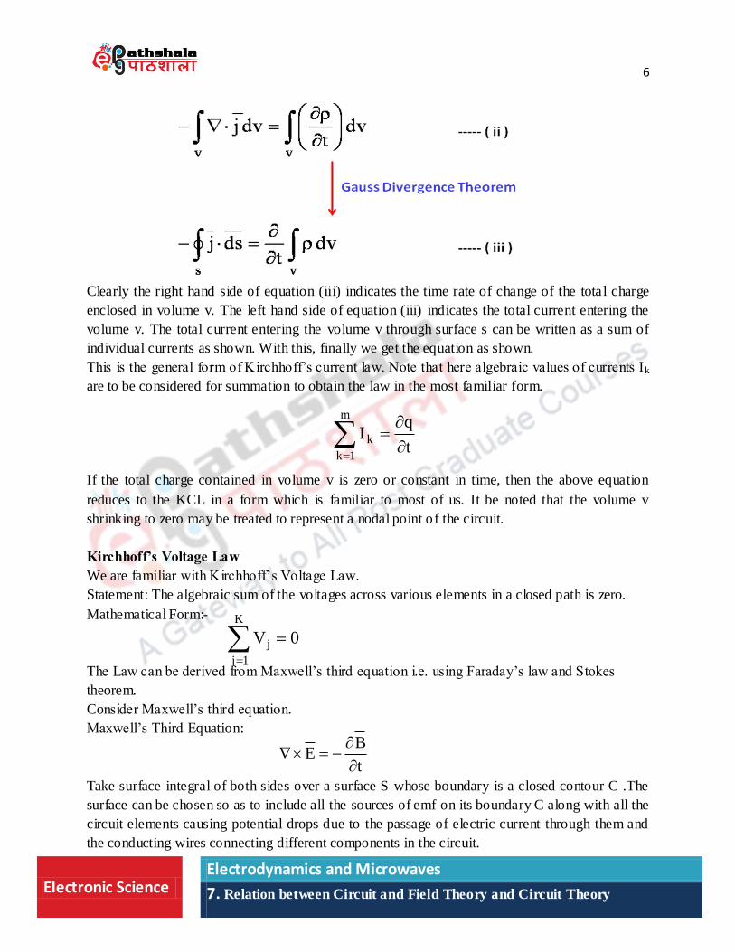
Taking volume integral of equation (i) and then applying Gauss Divergence theorem, we obtain
equation (iii) relating surface integral of free current density with volume integral of the time
rate of change of charge density as shown.
0I
m
1k
k
t
ρj0
ρD,t
DjH
t
DjH
6
Electronic Science Electrodynamics and Microwaves
7. Relation between Circuit and Field Theory and Circuit Theory
Clearly the right hand side of equation (iii) indicates the time rate of change of the total charge
enclosed in volume v. The left hand side of equation (iii) indicates the total current entering the
volume v. The total current entering the volume v through surface s can be written as a sum of
individual currents as shown. With this, finally we get the equation as shown.
This is the general form of Kirchhoff‟s current law. Note that here algebraic values of currents Ik
are to be considered for summation to obtain the law in the most familiar form.
If the total charge contained in volume v is zero or constant in time, then the above equation
reduces to the KCL in a form which is familiar to most of us. It be noted that the volume v
shrinking to zero may be treated to represent a nodal point of the circuit.
Kirchhoff’s Voltage Law
We are familiar with Kirchhoff‟s Voltage Law.
Statement: The algebraic sum of the voltages across various elements in a closed path is zero.
Mathematical Form:-
The Law can be derived from Maxwell‟s third equation i.e. using Faraday‟s law and Stokes
theorem.
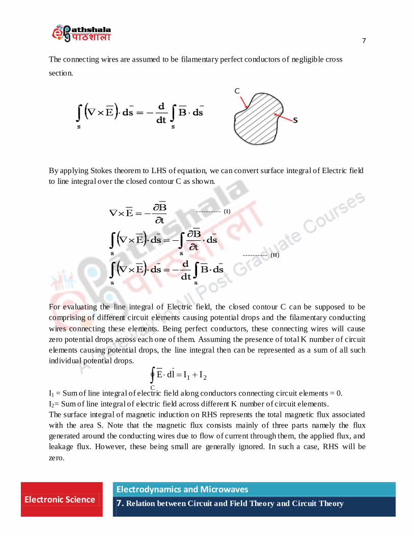
Consider Maxwell‟s third equation.
Maxwell‟s Third Equation:
Take surface integral of both sides over a surface S whose boundary is a closed contour C .The
surface can be chosen so as to include all the sources of emf on its boundary C along with all the
circuit elements causing potential drops due to the passage of electric current through them and
the conducting wires connecting different components in the circuit.
t
qI
m
1k
k
0V
K
1j
j
t
BE
7
Electronic Science Electrodynamics and Microwaves
7. Relation between Circuit and Field Theory and Circuit Theory
The connecting wires are assumed to be filamentary perfect conductors of negligible cross
section.
By applying Stokes theorem to LHS of equation, we can convert surface integral of Electric field
to line integral over the closed contour C as shown.
For evaluating the line integral of Electric field, the closed contour C can be supposed to be
comprising of different circuit elements causing potential drops and the filamentary conducting
wires connecting these elements. Being perfect conductors, these connecting wires will cause
zero potential drops across each one of them. Assuming the presence of total K number of circuit
elements causing potential drops, the line integral then can be represented as a sum of all such
individual potential drops.
I1 = Sum of line integral of electric field along conductors connecting circuit elements = 0.
I2= Sum of line integral of electric field across different K number of circuit elements.
The surface integral of magnetic induction on RHS represents the total magnetic flux associated
with the area S. Note that the magnetic flux consists mainly of three parts namely the flux
generated around the conducting wires due to flow of current through them, the applied flux, and
leakage flux. However, these being small are generally ignored. In such a case, RHS will be
zero.
21
C
IIldE
8
Electronic Science Electrodynamics and Microwaves
7. Relation between Circuit and Field Theory and Circuit Theory
Thus, finally we have KVL as shown.
It be noted that, in the literature, the derivations of Kirchhoff‟s Laws and some other results of
circuit theory have been discussed in variety of ways in much more details involving high level
of mathematical rigor and approximations. It is worth reading about them from the respective
references to have a better insight.
There exists variety of ways of derivations of Kirchhoff‟s Laws.
KVL applies to dc stationary circuit with time independent magnetic field density.
Kirchhoff‟s laws are corollaries of Maxwell's equations in the low frequency limit.
Kirchhoff‟s laws are applicable for lumped circuit model.
The applicability of KCL and KVL in general can be improved by considering parasitic
capacitance and inductance respectively.
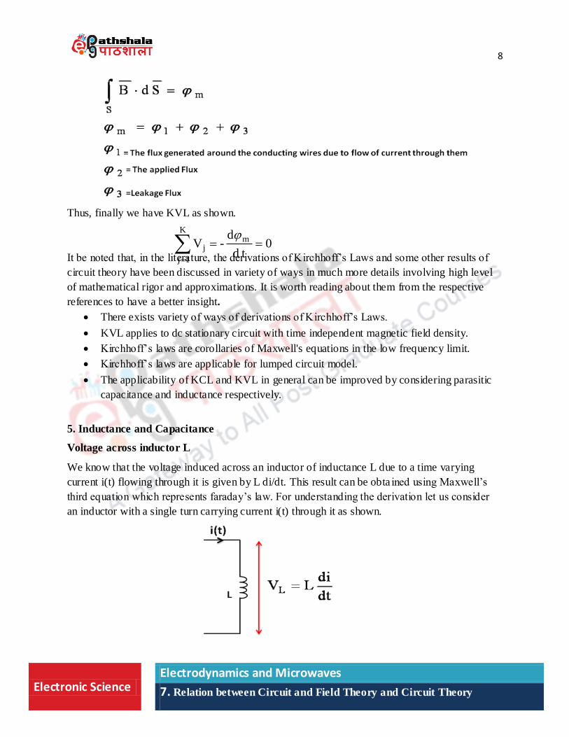
5. Inductance and Capacitance
Voltage across inductor L
We know that the voltage induced across an inductor of inductance L due to a time varying
current i(t) flowing through it is given by L di/dt. This result can be obta ined using Maxwell‟s
third equation which represents faraday‟s law. For understanding the derivation let us consider
an inductor with a single turn carrying current i(t) through it as shown.
0td
d-V m
K
1j
j
9
Electronic Science Electrodynamics and Microwaves
7. Relation between Circuit and Field Theory and Circuit Theory
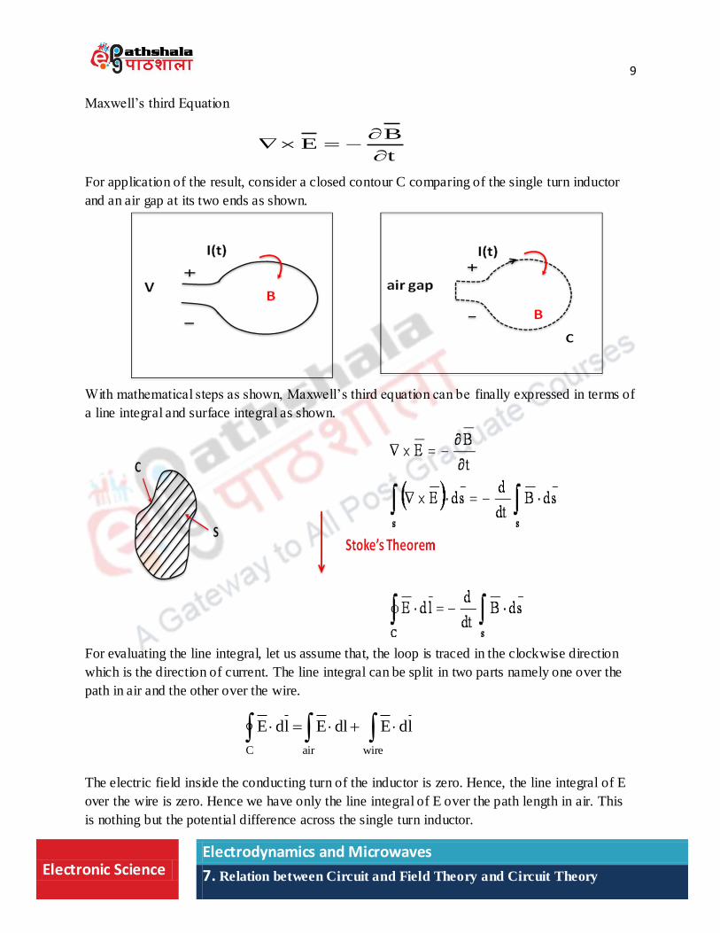
Maxwell‟s third Equation
t
BE
For application of the result, consider a closed contour C comparing of the single turn inductor
and an air gap at its two ends as shown.
With mathematical steps as shown, Maxwell‟s third equation can be finally expressed in terms of
a line integral and surface integral as shown.
For evaluating the line integral, let us assume that, the loop is traced in the clockwise direction
which is the direction of current. The line integral can be split in two parts namely one over the
path in air and the other over the wire.
The electric field inside the conducting turn of the inductor is zero. Hence, the line integral of E
over the wire is zero. Hence we have only the line integral of E over the path length in air. This
is nothing but the potential difference across the single turn inductor.
ldEdlEldE
wireairC
10
Electronic Science Electrodynamics and Microwaves
7. Relation between Circuit and Field Theory and Circuit Theory
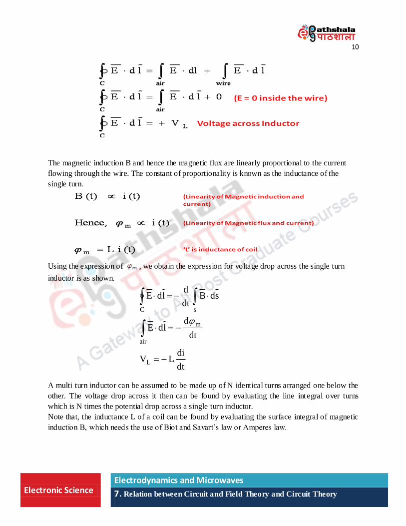
The magnetic induction B and hence the magnetic flux are linearly proportional to the current
flowing through the wire. The constant of proportionality is known as the inductance of the
single turn.
Using the expression of , we obtain the expression for voltage drop across the single turn
inductor is as shown.
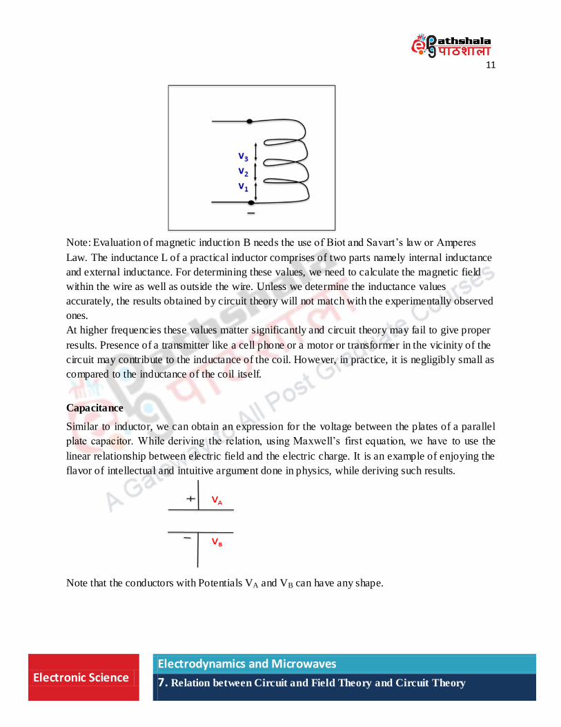
A multi turn inductor can be assumed to be made up of N identical turns arranged one below the
other. The voltage drop across it then can be found by evaluating the line integral over turns
which is N times the potential drop across a single turn inductor.
Note that, the inductance L of a coil can be found by evaluating the surface integral of magnetic
induction B, which needs the use of Biot and Savart‟s law or Amperes law.
dt
diLV
dt
dldE
sdBdt
dldE
L
m
air
sC
11
Electronic Science Electrodynamics and Microwaves
7. Relation between Circuit and Field Theory and Circuit Theory
Note: Evaluation of magnetic induction B needs the use of Biot and Savart‟s law or Amperes
Law. The inductance L of a practical inductor comprises of two parts namely internal inductance
and external inductance. For determining these values, we need to calculate the magnetic field
within the wire as well as outside the wire. Unless we determine the inductance values
accurately, the results obtained by circuit theory will not match with the experimentally observed
ones.
At higher frequencies these values matter significantly and circuit theory may fail to give proper
results. Presence of a transmitter like a cell phone or a motor or transformer in the vicinity of the
circuit may contribute to the inductance of the coil. However, in practice, it is negligibly small as
compared to the inductance of the coil itself.
Capacitance
Similar to inductor, we can obtain an expression for the voltage between the plates of a parallel
plate capacitor. While deriving the relation, using Maxwell‟s first equation, we have to use the
linear relationship between electric field and the electric charge. It is an example of enjoying the
flavor of intellectual and intuitive argument done in physics, while deriving such results.
Note that the conductors with Potentials VA and VB can have any shape.
12
Electronic Science Electrodynamics and Microwaves
7. Relation between Circuit and Field Theory and Circuit Theory
By applying field theory to any closed circuit, we obtain more general results. With some
assumptions, these results reduce to the results in forms familiar to us. Some of such assumptions
are as shown. Assumptions of perfect conducting wires with zero internal electric field, their
filamentary nature, static nature of circuit are some of the prominent assumptions.
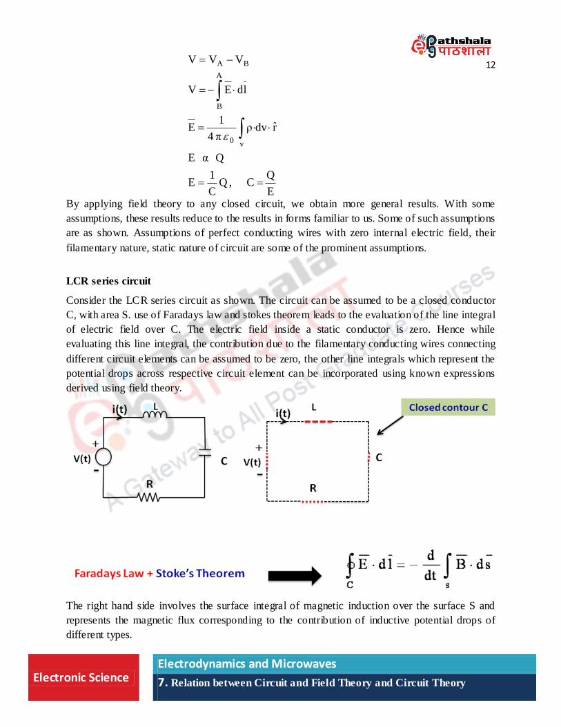
LCR series circuit
Consider the LCR series circuit as shown. The circuit can be assumed to be a closed conductor
C, with area S. use of Faradays law and stokes theorem leads to the evaluation of the line integral
of electric field over C. The electric field inside a static conductor is zero. Hence while
evaluating this line integral, the contribution due to the filamentary conducting wires connecting
different circuit elements can be assumed to be zero, the other line integrals which represent the
potential drops across respective circuit element can be incorporated using known expressions
derived using field theory.
The right hand side involves the surface integral of magnetic induction over the surface S and
represents the magnetic flux corresponding to the contribution of inductive potential drops of
different types.
E
QC,Q
C
1E
QαE
rdvρπ4
1E
ldEV
VVV
v0
A
B
BA
13
Electronic Science Electrodynamics and Microwaves
7. Relation between Circuit and Field Theory and Circuit Theory
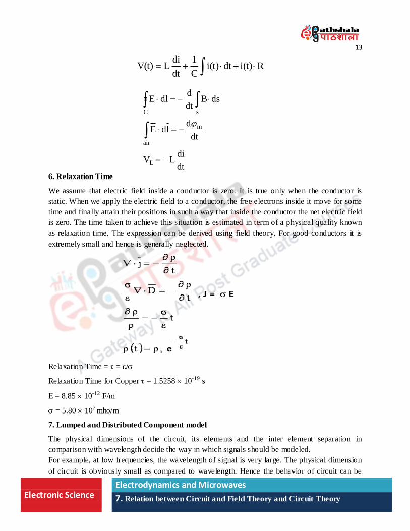
6. Relaxation Time
We assume that electric field inside a conductor is zero. It is true only when the conductor is
static. When we apply the electric field to a conductor, the free electrons inside it move for some
time and finally attain their positions in such a way that inside the conductor the net electric field
is zero. The time taken to achieve this situation is estimated in term of a physical quality known
as relaxation time. The expression can be derived using field theory. For good conductors it is
extremely small and hence is generally neglected.
Relaxation Time = = ε/
Relaxation Time for Copper = 1.5258 10-19 s
Ε = 8.85 10-12 F/m
= 5.80 107 mho/m
7. Lumped and Distributed Component model
The physical dimensions of the circuit, its elements and the inter element separation in
comparison with wavelength decide the way in which signals should be modeled.
For example, at low frequencies, the wavelength of signal is very large. The physical dimension
of circuit is obviously small as compared to wavelength. Hence the behavior of circuit can be
dt
diLV
dt
dldE
sdBdt
dldE
L
m
air
sC
Ri(t)dti(t)C
1
dt
diLV(t)
14
Electronic Science Electrodynamics and Microwaves
7. Relation between Circuit and Field Theory and Circuit Theory
modeled using “lumped element model”. Kirchhoff‟s laws are the basis of analysis of such
system. For DC signals with zero frequency, the wavelength is infinite. Hence Kirchhoff‟s laws
can be used without any difficulty.
At higher frequencies, when the distance between components are a significant fraction of the
wavelength or greater, the signals in the circuit are treated as waves, and are modeled using
transmission line theory which uses distributed nature of components.
In the case when the component dimensions are comparable with the wavelength then system
needs to be modeled using electromagnetic fields and wave theory.
One should not get confused in understanding the two terms namely drift velocity of electrons
and the speed of the signal which propagates through the conductor. Drift velocity depends upon
the applied electric field and mobility of the charge carrier. For electrons, it is extremely small.
(e.g. 0.2mm/s for copper) The speed of the signal, on the other hand, is related with the speed at
which the chance in voltage at one point is transmitted to other point in the circuit. This speed
depends upon the material of the conducting wire and composition of insulation and dielectric
properties of medium surrounding the conductor.
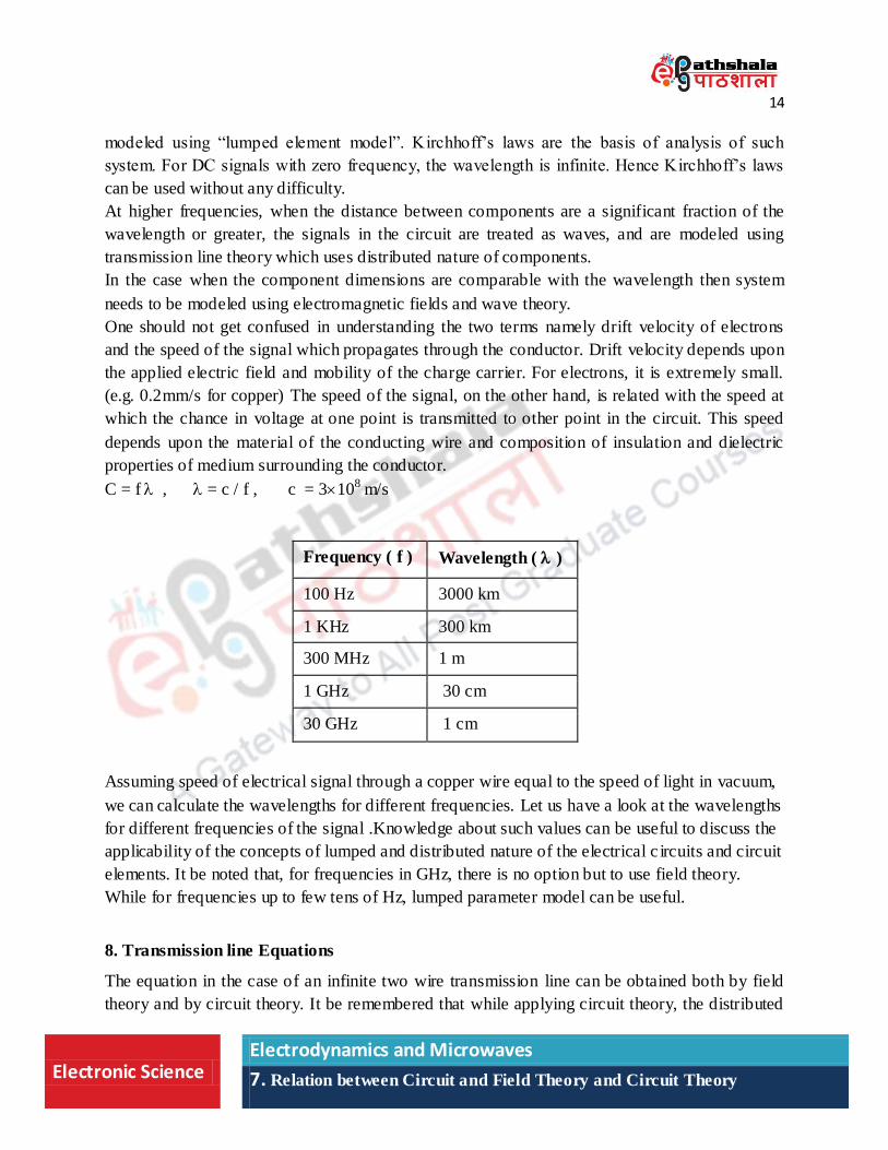
C = f , = c / f , c = 3108 m/s
Frequency ( f ) Wavelength ( )
100 Hz 3000 km
1 KHz 300 km
300 MHz 1 m
1 GHz 30 cm
30 GHz 1 cm
Assuming speed of electrical signal through a copper wire equal to the speed of light in vacuum,
we can calculate the wavelengths for different frequencies. Let us have a look at the wavelengths
for different frequencies of the signal .Knowledge about such values can be useful to discuss the
applicability of the concepts of lumped and distributed nature of the electrical c ircuits and circuit
elements. It be noted that, for frequencies in GHz, there is no option but to use field theory.
While for frequencies up to few tens of Hz, lumped parameter model can be useful.
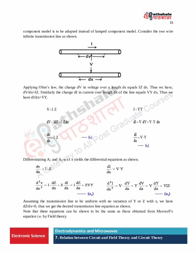
8. Transmission line Equations
The equation in the case of an infinite two wire transmission line can be obtained both by field
theory and by circuit theory. It be remembered that while applying circuit theory, the distributed
15
Electronic Science Electrodynamics and Microwaves
7. Relation between Circuit and Field Theory and Circuit Theory
component model is to be adopted instead of lumped component model. Consider the two wire
infinite transmission line as shown.
Applying Ohm‟s law, the change dV in voltage over a length dx equals IZ dx. Thus we have,
dV/dx=IZ. Similarly the change dI in current over length dx of the line equals VY dx. Thus we
have dI/dx=VY.
Differentiating A1 and A2 w.r.t x yields the differential equations as shown.
Assuming the transmission line to be uniform with no variation of Y or Z with x, we have
dZ/dx=0, thus we get the desired transmission line equation as shown.
Note that these equations can be shown to be the same as those obtained from Maxwell‟s
equation i.e. by Field theory.
16
Electronic Science Electrodynamics and Microwaves
7. Relation between Circuit and Field Theory and Circuit Theory
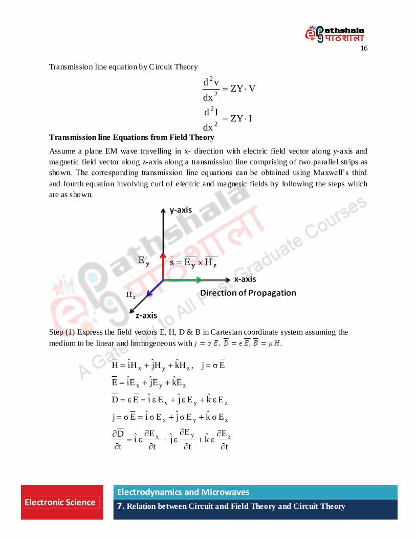
Transmission line equation by Circuit Theory
Transmission line Equations from Field Theory
Assume a plane EM wave travelling in x- direction with electric field vector along y-axis and
magnetic field vector along z-axis along a transmission line comprising of two parallel strips as
shown. The corresponding transmission line equations can be obtained using Maxwell‟s third
and fourth equation involving curl of electric and magnetic fields by following the steps which
are as shown.
Step (1) Express the field vectors E, H, D & B in Cartesian coordinate system assuming the
medium to be linear and homogeneous with .
IZYdx
Id
VZYdx
vd
2
2
2
2
t
Eεk
t
Eεj
t
Eεi
t
D
EσkEσjEσiEσj
EεkEεjEεiEεD
EkEjEiE
Eσj,HkHjHiH
zyx
zyx
zyx
zyx
zyx
17
Electronic Science Electrodynamics and Microwaves
7. Relation between Circuit and Field Theory and Circuit Theory
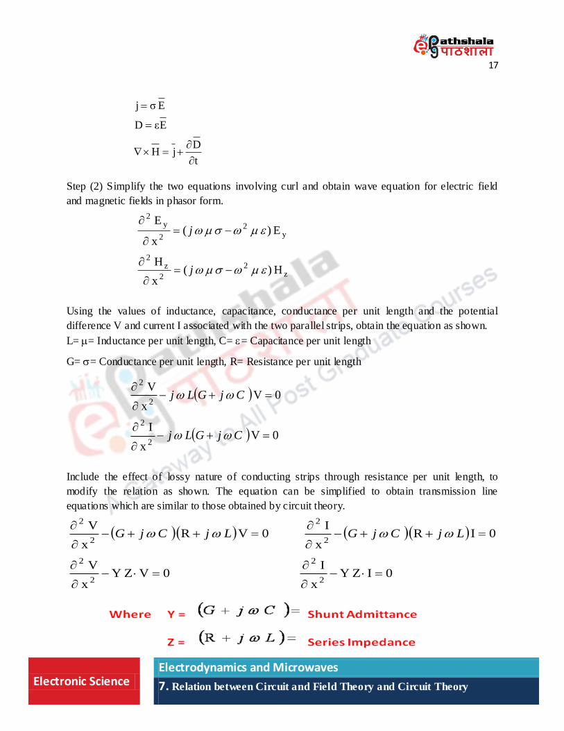
Step (2) Simplify the two equations involving curl and obtain wave equation for electric field
and magnetic fields in phasor form.
Using the values of inductance, capacitance, conductance per unit length and the potential
difference V and current I associated with the two parallel strips, obtain the equation as shown.
L= = Inductance per unit length, C= = Capacitance per unit length
G= = Conductance per unit length, R= Resistance per unit length
Include the effect of lossy nature of conducting strips through resistance per unit length, to
modify the relation as shown. The equation can be simplified to obtain transmission line
equations which are similar to those obtained by circuit theory.
0IZYx
I0VZY
x
V
0IRx
I0VR
x
V
2
2
2
2
2
2
2
2
LjCjGLjCjG
t
DjH
EεD
Eσj
z2
2
z2
y2
2
y2
H)(x
H
E)(x
E
j
j
0Vx
I
0Vx
V
2
2
2
2
CjGLj
CjGLj
18
Electronic Science Electrodynamics and Microwaves
7. Relation between Circuit and Field Theory and Circuit Theory
9. Wave guides, Cavity Resonators and Antenna
We know that, circuit theory applies mainly to closed paths in which there is a return path for the
current to arrive at the starting point. Can we discuss the transfer of EM ene rgy from one point
to the other, in the case of a system having no return path for the current? We can have such
systems of conductors known as wave guides. Different types of wave guides can be found to be
discussed in literature. For example, consider a hollow conductor in the form of a cylinder or a
rectangular parallelepiped. It has no return path. Hence, it cannot be treated as a circuit. Then can
it transmit electromagnetic energy through it?
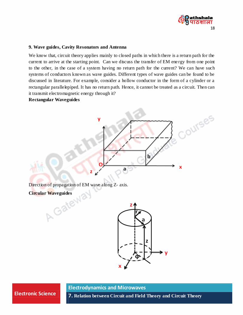
Rectangular Waveguides
Direction of propagation of EM wave along Z- axis.
Circular Waveguides
19
Electronic Science Electrodynamics and Microwaves
7. Relation between Circuit and Field Theory and Circuit Theory
As per the norms of circuit theory, the answer is “No”. However, it is not the case. Waveguides
can propagate higher modes of EM waves which have components of E & H in the direction of
propagation. It is also observed that, such waveguides allow the transfer of EM energy, if the
frequency of EM wave is above some particular frequency known as cut off frequency. EM wave
with frequency below the cut off frequency cannot propagate through the wave guide. For a
given mode, the cut off frequency depends upon the geometry of the wave guide and can be
computed using EM Field theory only.
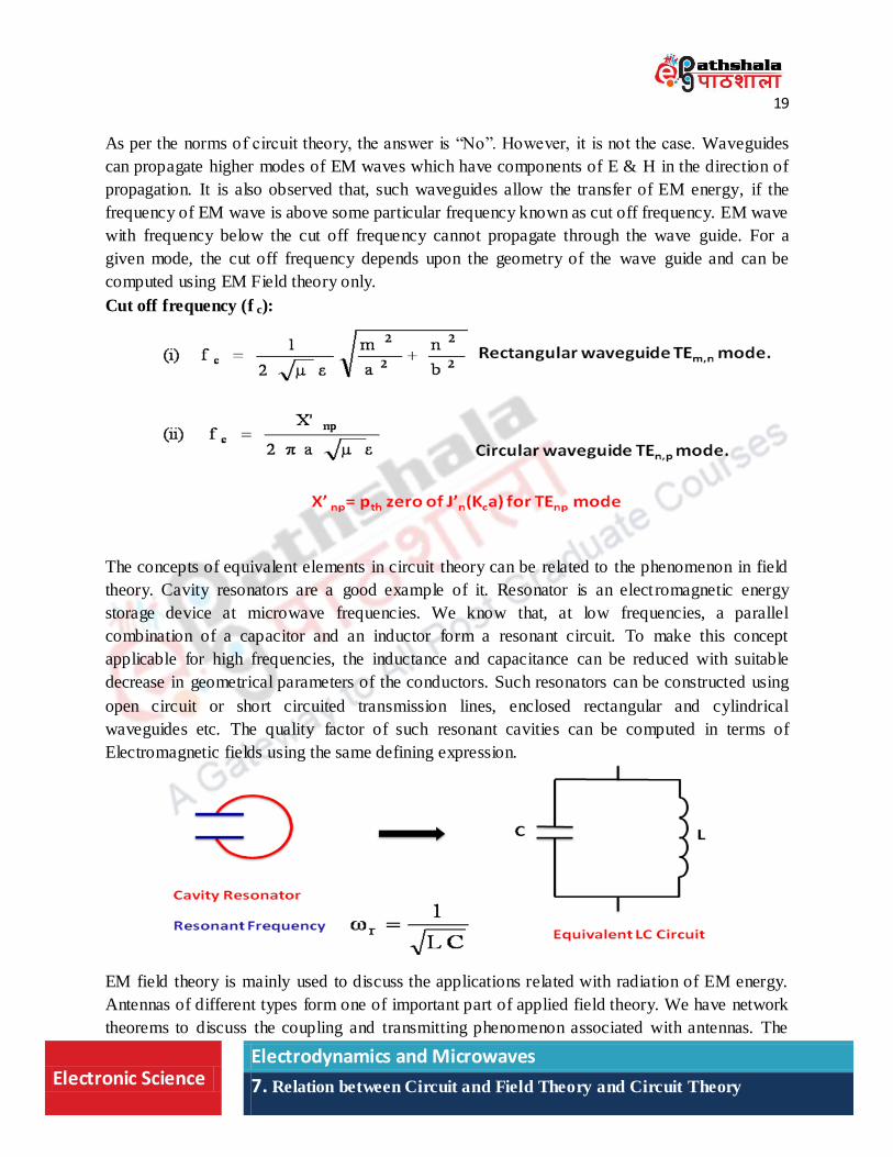
Cut off frequency (f c):
The concepts of equivalent elements in circuit theory can be related to the phenomenon in field
theory. Cavity resonators are a good example of it. Resonator is an elect romagnetic energy
storage device at microwave frequencies. We know that, at low frequencies, a parallel
combination of a capacitor and an inductor form a resonant circuit. To make this concept
applicable for high frequencies, the inductance and capacitance can be reduced with suitable
decrease in geometrical parameters of the conductors. Such resonators can be constructed using
open circuit or short circuited transmission lines, enclosed rectangular and cylindrical
waveguides etc. The quality factor of such resonant cavities can be computed in terms of
Electromagnetic fields using the same defining expression.
EM field theory is mainly used to discuss the applications related with radiation of EM energy.
Antennas of different types form one of important part of applied field theory. We have network
theorems to discuss the coupling and transmitting phenomenon associated with antennas. The
20
Electronic Science Electrodynamics and Microwaves
7. Relation between Circuit and Field Theory and Circuit Theory
concepts of circuit Theory along with these theorems can be found useful for developing the
devices using phenomenon of radiation of energy.
Network Theorems for Antenna: Various antennas network theorems are useful for discussion
of the coupling and transmitting phenomenon (like transmission and reception) associated with
antennas.
Theorem 1: Equality of directive pattern of antenna
Statement – The direction pattern of an antenna as a receiving antenna is identical to that when
used as a transmitting antenna.
Theorem 2: Equivalence of Transmitting and receiving antenna Impedance
Statement – The impedance of an isolated antenna used for transmitting as well receiving
purpose are identical.
10. Magnetic circuits
For development of many devices we make use of magnetic energy along with electrical energy.
Transformers play an important role in this regards. For a desired fraction of the flux linkage
between primary and secondary coils of the transformers, cores of different shapes and size made
up of ferromagnetic materials having specific magnetic properties are employed. Naturally one
may ask “How such magnetically coupled systems are designed or analyzed?” can we have
magnetic circuit which deal with transfer of magnetic energy?
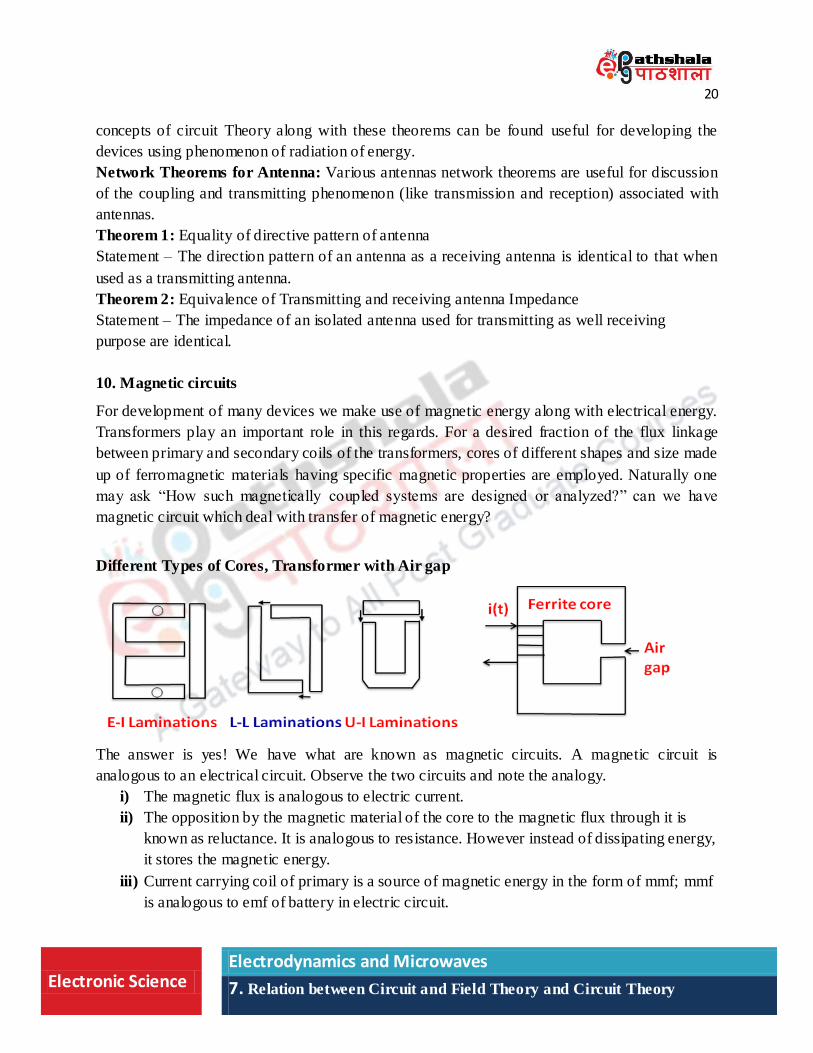
Different Types of Cores, Transformer with Air gap
The answer is yes! We have what are known as magnetic circuits. A magnetic circuit is
analogous to an electrical circuit. Observe the two circuits and note the analogy.
i) The magnetic flux is analogous to electric current.
ii) The opposition by the magnetic material of the core to the magnetic flux through it is
known as reluctance. It is analogous to resistance. However instead of dissipating energy,
it stores the magnetic energy.
iii) Current carrying coil of primary is a source of magnetic energy in the form of mmf; mmf
is analogous to emf of battery in electric circuit.
21
Electronic Science Electrodynamics and Microwaves
7. Relation between Circuit and Field Theory and Circuit Theory
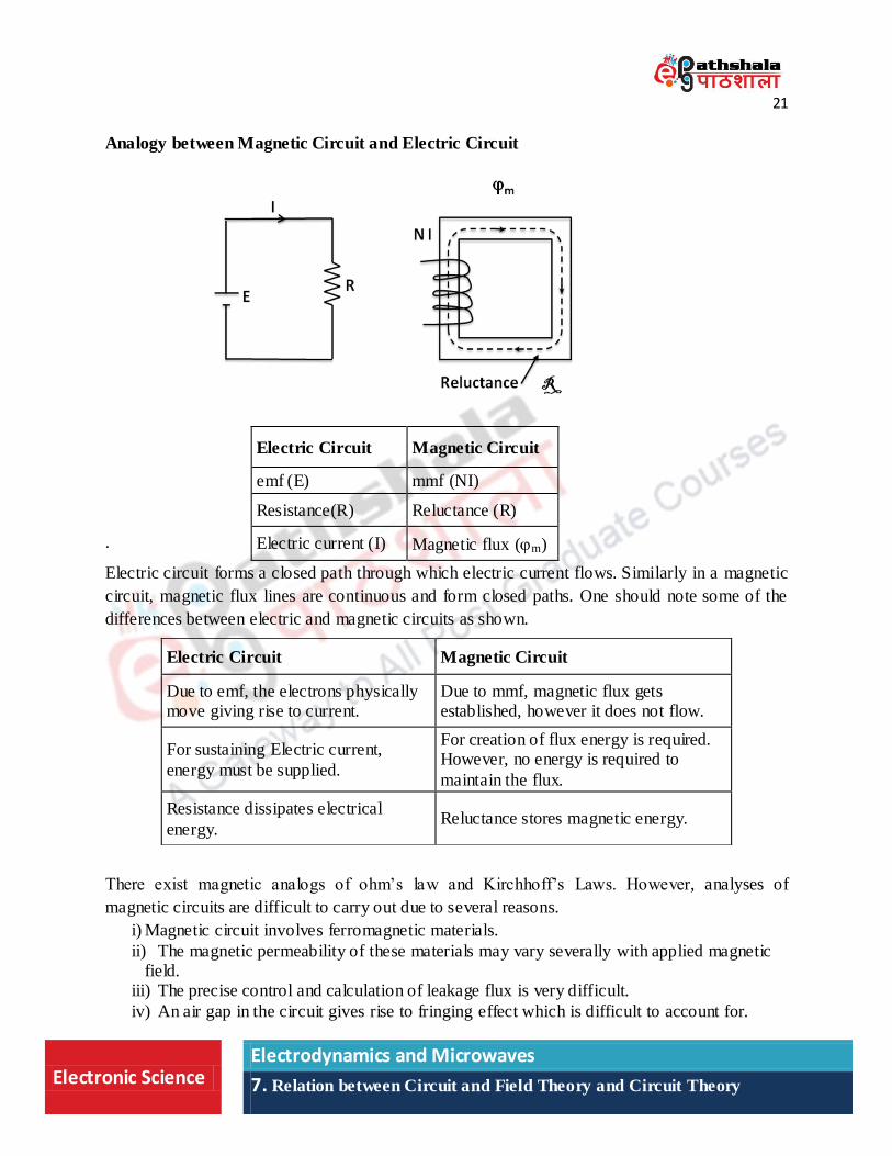
Analogy between Magnetic Circuit and Electric Circuit
.
Electric circuit forms a closed path through which electric current flows. Similarly in a magnetic
circuit, magnetic flux lines are continuous and form closed paths. One should note some of the
differences between electric and magnetic circuits as shown.
There exist magnetic analogs of ohm‟s law and Kirchhoff‟s Laws. However, analyses of
magnetic circuits are difficult to carry out due to several reasons.
i) Magnetic circuit involves ferromagnetic materials.
ii) The magnetic permeability of these materials may vary severally with applied magnetic field.
iii) The precise control and calculation of leakage flux is very difficult.
iv) An air gap in the circuit gives rise to fringing effect which is difficult to account for.
Electric Circuit Magnetic Circuit
emf (E) mmf (NI)
Resistance(R) Reluctance (R)
Electric current (I) Magnetic flux (m)
Electric Circuit Magnetic Circuit
Due to emf, the electrons physically move giving rise to current.
Due to mmf, magnetic flux gets established, however it does not flow.
For sustaining Electric current,
energy must be supplied.
For creation of flux energy is required. However, no energy is required to
maintain the flux.
Resistance dissipates electrical
energy. Reluctance stores magnetic energy.
22
Electronic Science Electrodynamics and Microwaves
7. Relation between Circuit and Field Theory and Circuit Theory
Electric Circuit Magnetic Circuit
Ohm’s Law e =I R em= R
Kirchhoff’s Current Law I = 0 =0
Kirchhoff’s Voltage Law emf = 0 mmf = =S=
11. Numerical and Graphical techniques
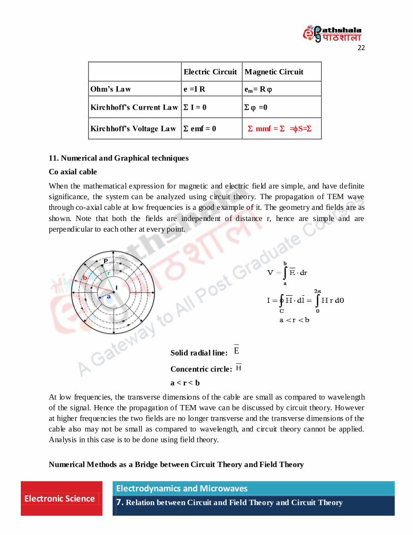
Co axial cable
When the mathematical expression for magnetic and electric field are simple, and have definite
significance, the system can be analyzed using circuit theory. The propagation of TEM wave
through co-axial cable at low frequencies is a good example of it. The geometry and fields are as
shown. Note that both the fields are independent of distance r, hence are simple and are
perpendicular to each other at every point.
Solid radial line: E
Concentric circle: H
a < r < b
At low frequencies, the transverse dimensions of the cable are small as compared to wavelength
of the signal. Hence the propagation of TEM wave can be discussed by circuit theory. However
at higher frequencies the two fields are no longer transverse and the transverse dimensions of the
cable also may not be small as compared to wavelength, and circuit theory cannot be applied.
Analysis in this case is to be done using field theory.
Numerical Methods as a Bridge between Circuit Theory and Field Theory
23
Electronic Science Electrodynamics and Microwaves
7. Relation between Circuit and Field Theory and Circuit Theory
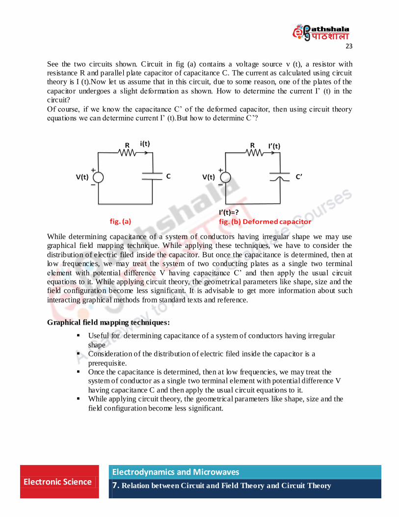
See the two circuits shown. Circuit in fig (a) contains a voltage source v (t), a resistor with resistance R and parallel plate capacitor of capacitance C. The current as calculated using circuit theory is I (t).Now let us assume that in this circuit, due to some reason, one of the plates of the
capacitor undergoes a slight deformation as shown. How to determine the current I‟ (t) in the circuit?
Of course, if we know the capacitance C‟ of the deformed capacitor, then using circuit theory equations we can determine current I‟ (t).But how to determine C‟?
While determining capacitance of a system of conductors having irregular shape we may use graphical field mapping technique. While applying these techniques, we have to consider the
distribution of electric filed inside the capacitor. But once the capacitance is determined, then at low frequencies, we may treat the system of two conducting plates as a single two terminal
element with potential difference V having capacitance C‟ and then apply the usual circuit equations to it. While applying circuit theory, the geometrical parameters like shape, size and the field configuration become less significant. It is advisable to get more information about such
interacting graphical methods from standard texts and reference.
Graphical field mapping techniques:
Useful for determining capacitance of a system of conductors having irregular
shape Consideration of the distribution of electric filed inside the capacitor is a
prerequisite. Once the capacitance is determined, then at low frequencies, we may treat the
system of conductor as a single two terminal element with potential difference V
having capacitance C and then apply the usual circuit equations to it. While applying circuit theory, the geometrical parameters like shape, size and the
field configuration become less significant.
24
Electronic Science Electrodynamics and Microwaves
7. Relation between Circuit and Field Theory and Circuit Theory
12. Summary
Thus to summarize, we may say that,
i) Circuit theory, though being an approximation of field theory, is simpler and more useful in many practical applications.
ii) Basic laws and results used in circuit theory can be derived using the concepts of
field theory. iii) The assumptions, under which circuit theory becomes applicable, can be better
understood using field theory. iv) The electrical circuits can be analyzed assuming lumped or distributed type, by
noting the dimensions of the circuit in comparison with the wavelength of the
electrical signal. v) Magnetic circuits can be analyzed using their analogy with electrical circuits.
vi) Some systems like antenna, waveguide etc dealing with EM radiation can be discussed with the help of field theory only.