modern breakwater solution of geotextile tube in uae · - pilarczyk, k. w. (1999). geosynthetics...
TRANSCRIPT
The
Mas
terb
uild
er |
Aug
ust 2
015
| ww
w.m
aste
rbui
lder
.co.
in15
6
Modern Breakwater Solution of Geotextile Tube in UAE
Abstract: In 2011, the UAE Government announced the con-struction of a new fishing port in Ras Al Khaimah City includ-ing new breakwater structure with a total length of 700m. The breakwater encloses and protects the entire area of the new fishing port. Due to the economic slowdown which started in 2009, the Government was looking for ways to reduce cost spending and started to look for alternatives based on value engineering. Considering all factors, a design using geo-tex-tile tubes filled with dredged sand from the seabed as core material for the breakwater, was proposed. The circumfer-ence of the geotextile tubes varies between 8.6m to 12.9m and lengths between 10m to 50m long to form 4 layers of barriers as a breakwater. Currently this is the largest scale geo-textile tube breakwater application in the UAE.
A breakwater is a man-made structure protecting a shoreline area, port or anchorage from waves and tidal cur-rents. Some breakwaters are built towards the seaward limit of the intertidal zone some are parallel (or nearly parallel) to the shore which are called offshore breakwater. Breakwa-ters may be either fixed or floating and its choice depends on water depth and tidal range. Breakwater construction is usually parallel or perpendicular to the coastline to maintain tranquil condition in the port. Most breakwater construction depends upon wave condition and considering some other en-vironmental parameters. There are many alternative meth-ods to consider in order to construct the breakwater such as caisson type, rubble mound, precast concrete blocks, etc. Each one of these methods has its own unique characteristics as well as its building process. The appointed consultant chose one of the above mentioned conventional methods and es-timated the cost of construction of a fishing harbor for 250 berths. This estimate was used as a base for establishing the budget for the project, due to the economic slowdown which started in 2009, the UAE Government was looking for cost-effective and innovative engineering solution and as such a geotextile tube breakwater was chosen.
Project Description
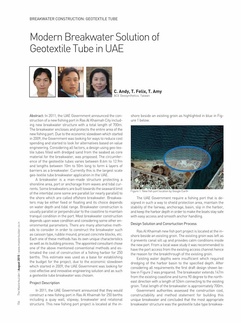
In 2011, the UAE Government announced that they would construct a new fishing port in Ras Al Khaimah for 250 berths including a quay wall, slipway, breakwater and relational structure. This new fishing port project is located at the in-
shore beside an existing groin as highlighted in blue in Fig-ure 1 below.
C. Andy, T. Felix, T. AmyACE Geosynthetics. Taiwan
Figure 1. New fish port location by Google Earth
The UAE Government require a fishing port that is de-signed in such a way to shield protection area, maintain the stability of the fairway, anchorage, basin, slip in the harbor, and keep the harbor depth in order to make the boats stay safe with easy access and smooth anchor handling.
Design Solution and Consrtuction Process
Ras Al Khaimah new fish port project is located at the in-shore beside an existing groin. The existing groin was left as it prevents canal silt up and provides calm conditions inside the new port. From a local wave study it was recommended to have the port access from the existing access channel hence the reason for the breakthrough of the existing groin.
Existing water depths were insufficient which required dredging of the harbor basin to the specified depth. After considering all requirements the first draft design shown be-low in Figure 2 was prepared. The breakwater extends 147m from the existing coastline and turns 90 degree to the north-east direction with a length of 524m connecting to the existing groin. Total length of the breakwater is approximately 700m.
Government authorities assessed the construction cost, constructability and method statement for building this unique breakwater and concluded that the most appropriate breakwater structure was the geotextile tube type breakwa-
BREAKWATER CONSTRUCTION: GEOTEXTILE TUBE

157The M
asterbuilder | August 2015 | w
ww
.masterbuilder.co.in
BREAKWATER CONSTRUCTION: GEOTEXTILE TUBE
ter filled with sand from the harbour basin covered with a rock armour layer. The major cost reduction could only be achieved by using geotextile tubes in the core of the breakwa-ter instead of the common rubble mound material to construct the main body of breakwater. Furthermore is resolve the sea bed dredge problem as well as the slurry from dredging the harbour basin was used to the geotextile tubes further re-ducing the high dredging costs. After the breakwater main body was completed, the breakwater was cover with a layer of rock filter and armour rock to protect the breakwater and to dissipate the wave energy.
Bathymetric survey of the existing seabed show water depths of average -1 m, reference is made to Figure 3 after dredging an average water depth of -2.5 to -3.0m is found at the harbour basin.
the geotextile tubes vary on lengths between 10m to 50m. In order to prevent erosion during construction a scour apron and anchor tube is placed below the bottom geotextile tube.
Two layers of rock i.e. filter rock layer and armour rock layer are used to protect geotextile tube. Filter layer is placed to prevent the rock damaging the geotextile tubes during placement a armour rock including an additional layer of geotextile. In total 4 layers of geotextile tubes stacked on top of each other to reach 6 m height including aforementioned rock layers. Total quantity of geotextile tubes used in the breakwater is 286 units including 33 geotextile apron units.
As can be seen in Figure 6, construction sequence started from the shoreline towards the 90 degree corner. Each section must be surveyed prior to installation to avoid the geotextile tube damage or wrong installation location.
Figure 3: Existing water depths
Figure 5. Construction at the start
Figure 6. Construction started from shoreline by Google Earth
Figure 7. Compaction of sand layersFigure 4. Typical cross section breakwater
Figure 2: First draft layout of new fish port
Highest water level at the new fishing port ranges is +2.5 m H.A.T.. During stormy conditions a maximum wave height of +3.5m can occur. The design engineer considered many factors as overtopping, wave runup, wave angle, slope, tidal and local current. Based on all design parameters involved a breakwater profile with a crest height of +6m was deemed sufficient to protect the port from extreme weather conditions.
Breakwater is build up out of 4 layers i.e. geotextile tubes filled with dredged sand from the seabed used as core ma-terial for the breakwater. Between geotextile tubes dredge sand is placed and compacted covered up with geotextile mats. Reference is made to Figure 4 for typical cross section of the breakwater.
The top layer of geotextile tube has a circumference of 8.6 m and the remaining layers of geotextile tubes have a circumference of 12.9 m. Due to the long and bend structure,
Core filled is compacted after placement reference is made to Figure 7.
The
Mas
terb
uild
er |
Aug
ust 2
015
| ww
w.m
aste
rbui
lder
.co.
in15
8
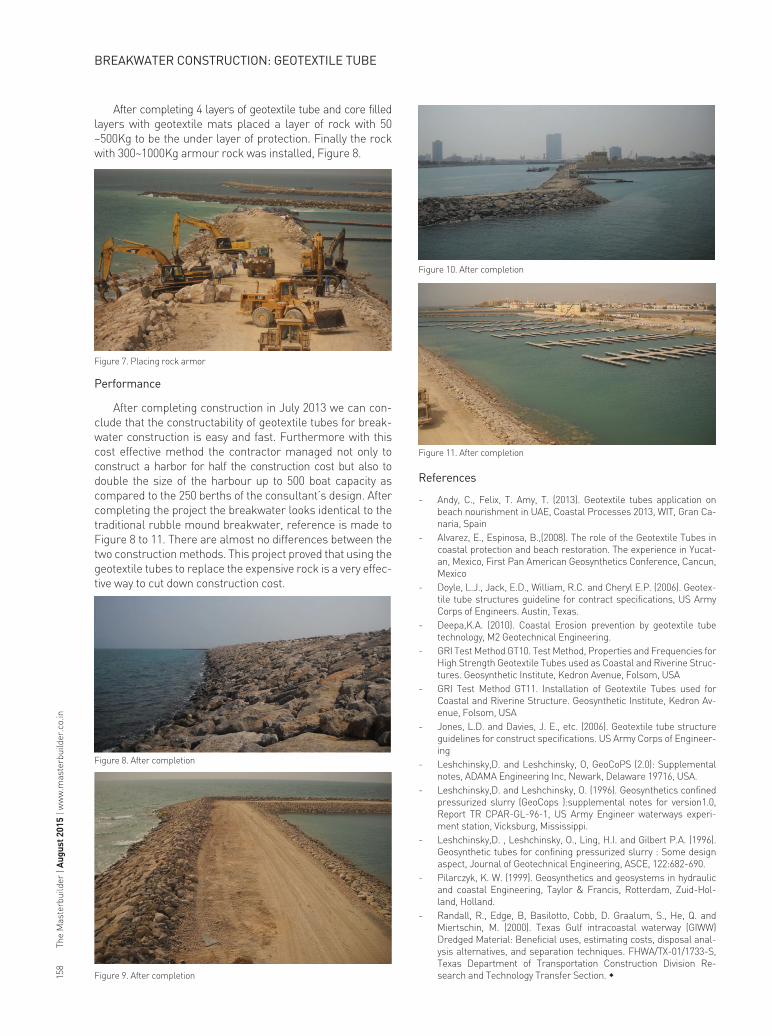
After completing 4 layers of geotextile tube and core filled layers with geotextile mats placed a layer of rock with 50 ~500Kg to be the under layer of protection. Finally the rock with 300~1000Kg armour rock was installed, Figure 8.
Figure 7. Placing rock armor
Figure 10. After completion
Figure 11. After completion
Figure 8. After completion
Figure 9. After completion
Performance
After completing construction in July 2013 we can con-clude that the constructability of geotextile tubes for break-water construction is easy and fast. Furthermore with this cost effective method the contractor managed not only to construct a harbor for half the construction cost but also to double the size of the harbour up to 500 boat capacity as compared to the 250 berths of the consultant’s design. After completing the project the breakwater looks identical to the traditional rubble mound breakwater, reference is made to Figure 8 to 11. There are almost no differences between the two construction methods. This project proved that using the geotextile tubes to replace the expensive rock is a very effec-tive way to cut down construction cost.
References
- Andy, C., Felix, T. Amy, T. (2013). Geotextile tubes application on beach nourishment in UAE, Coastal Processes 2013, WIT, Gran Ca-naria, Spain
- Alvarez, E., Espinosa, B.,(2008). The role of the Geotextile Tubes in coastal protection and beach restoration. The experience in Yucat-an, Mexico, First Pan American Geosynthetics Conference, Cancun, Mexico
- Doyle, L.J., Jack, E.D., William, R.C. and Cheryl E.P. (2006). Geotex-tile tube structures guideline for contract specifications, US Army Corps of Engineers. Austin, Texas.
- Deepa,K.A. (2010). Coastal Erosion prevention by geotextile tube technology, M2 Geotechnical Engineering.
- GRI Test Method GT10. Test Method, Properties and Frequencies for High Strength Geotextile Tubes used as Coastal and Riverine Struc-tures. Geosynthetic Institute, Kedron Avenue, Folsom, USA
- GRI Test Method GT11. Installation of Geotextile Tubes used for Coastal and Riverine Structure. Geosynthetic Institute, Kedron Av-enue, Folsom, USA
- Jones, L.D. and Davies, J. E., etc. (2006). Geotextile tube structure guidelines for construct specifications. US Army Corps of Engineer-ing
- Leshchinsky,D. and Leshchinsky, O, GeoCoPS (2.0): Supplemental notes, ADAMA Engineering Inc, Newark, Delaware 19716, USA.
- Leshchinsky,D. and Leshchinsky, O. (1996). Geosynthetics confined pressurized slurry (GeoCops ):supplemental notes for version1.0, Report TR CPAR-GL-96-1, US Army Engineer waterways experi-ment station, Vicksburg, Mississippi.
- Leshchinsky,D. , Leshchinsky, O., Ling, H.I. and Gilbert P.A. (1996). Geosynthetic tubes for confining pressurized slurry : Some design aspect, Journal of Geotechnical Engineering, ASCE, 122:682-690.
- Pilarczyk, K. W. (1999). Geosynthetics and geosystems in hydraulic and coastal Engineering, Taylor & Francis, Rotterdam, Zuid-Hol-land, Holland.
- Randall, R., Edge, B, Basilotto, Cobb, D. Graalum, S., He, Q. and Miertschin, M. (2000). Texas Gulf intracoastal waterway (GIWW) Dredged Material: Beneficial uses, estimating costs, disposal anal-ysis alternatives, and separation techniques. FHWA/TX-01/1733-S, Texas Department of Transportation Construction Division Re-search and Technology Transfer Section. w
BREAKWATER CONSTRUCTION: GEOTEXTILE TUBE