modeling and simulation for green and renewable · pdf filemodeling and simulation for green...
TRANSCRIPT

Modeling and Simulation for Green and Renewable EnergyPeter van Duijsen1, Frank Chen2
1Simulation Research, The Netherlands, [email protected], Taiwan, [email protected]
Keywords: Modeling, Simulation, Renewable, Green Energy, Solar, Wind Power, Hybrid Electrical Vehicle
AbstractThis paper focuses on the use of Modeling and Simulationin the design and verification process for Renewable andGreen Energy. First the role of electrical energy isdiscussed and second samples are given where modelingand simulation can be applied. Samples include wind andsolar power, Hybrid Electrical Vehicles (HEV) and FuelCell simulations.
IntroductionGreen Energy will effect the quality of our life in the nearfuture. With limited fossil energy resources available, it isonly a matter of time when we will change our focus onrenewable and clean green energy.There are many discussions going on about the type ofenergy storage and transportation. The two maincandidates for storage and transportation are hydrogen andelectricity. Since electrical energy is the most practical togenerate and transport, it is favored over hydrogen.However storage of electrical energy is more difficult andrequires other physical means for storage. For high energylevels, water storage on different altitudes is a proventechnology. For automotive and mobile applications,batteries, super capacitors, or mechanical flywheelsbecome more practical. Fuel cells for automotiveapplications and even for small mobile apparatus are indevelopment.A combination of efficient energy storage in the form ofhydrogen and generation of electricity by fuel cells seemsto be the most promising alternative to fossil energyresources. However the practical question remains, wheredo we get the power to produce H2
Focus of the paperThe main focus is on electrical energy is duringgeneration and transport. Storage is required for peakshaving and automotive and mobile applications. In thispaper we will focus on the generation, transport, storageand control of electrical energy. Samples are given forhigh power and automotive applications as well as for lowpower levels such as White Led drivers. The focus isdirected towards applications applying renewable andgreen energy for generation, transport, storage and use.
What is Green Energy?Every now and then, new buzzwords start to appear andthis is also true for electrical engineering. The term GreenEnergy can be associated with environment-friendlygeneration, transport, storage and use of energy. If wecompare the use of electrical energy for railway
applications with a steam locomotive, the advantage ofelectrical energy for preserving the environment isevident. However, where is this electrical energyproduced? You can not simply get it like other naturalenergy resources like coal or oil. Remember that burningcoal, oil and methane produces a substantial part of theelectrical energy that we use today. And we are not sofond of nuclear power, mainly to its waste problem! Theseare all fossil energy resources that are not part of ourdefinition of Green Energy. Solar power, wind power, andthe natural flow of water are resources that comply withour definition of Green Energy. Since the natural fossilenergy resources are limited on this planet, we have to putour focus on green power generation like solar and windpower.Taking into consideration the environment-friendlycharacter of electrical energy, we can state that at least fortransport, storage and use, electrical energy is our favorite.In the next sections we will discuss the generation,transport storage and use of electrical energy.
Generation of electrical energyIf we look at electrical energy, we can state that it isGreen Energy, when it comes to transport storage and use.Only the generation of electrical energy with using fossilenergy resources such as solar or wind power can beconsidered Green Energy. Also a Fuel Cell is consideredas Green Energy, but remember that somewhere thehydrogen has to be produced.
Transport of electrical energyTransport of electrical energy seems to be very simple,just use some cables, and the job seems to be done. Thisseems to be true on short or medium distances, buttransporting electrical energy from one continent toanother is a major challenge and losses during transportbecome significant.
Storage of electrical energyStorage of electrical energy is possible for low power. Forexample, batteries are common in use, but have seriouslimitation when it comes to power level, life time,production and pollution due waste. Also the energydensity/ weight ratio is far less compared to fossil energyresources. As an example, a liter of gasoline will get youmuch further than a fully charged battery if 1Kg.On a larger scale, hydrogen could be stored more easilyand could be generated from electrical energy. Storage inthe form of mechanical power such as with a flywheel forautomotive applications only found serious use in publictransport. Super capacitors are a promising component,

but still partly in the development stage. Storage in theform of hydrogen seems to be the most promisingcandidate for the future.
Use of electrical energyThe use of electrical energy is straightforward and wellaccepted. There are exceptions in certain areas, forexample such automotive, aeronautics, space exploration,industrial heating and welding and heating of buildings,where due to storage and the high power levelrequirements, electrical energy is not very practical.
Solar Power
Solar Power seems to be the most efficient way ofgenerating energy from the sun, but the production ofsolar cells is expensive and environment-unfriendly.Furthermore, the efficiency of the solar cell is low. In thissample the non-linear characteristic of the solar cell issimulated, showing the current dependency of the outputvoltage. The solar cell is a current source up to its nominalpower. As soon as the maximum power is reached, thecurrent drops to lower levels. In this sample, current levelsup to 3A are possible, up to 120 Watt.
Figure 1: Solar Cell characteristics.
Wind Power
Wind Power is very popular nowadays, because of thehigh power that can be achieved in an efficient way. If wemodel the energy produced by wind power, we have tomodel all components in the system. First the windturbine has to be modeled, including the mechanical drivetrain, such as shafts, gearboxes and bearings. Second theelectrical machine, mostly a synchronous machine, ismodeled in detail and connected to a model of the powerelectronics, such as AC-DC or back to back converters(AC-DC-AC with variable frequency). The control of thewind turbine needs special attention. The pitch control isimportant, since the efficiency is greatly influenced by thepitch of the rotor blades. In the simulation shown in figure2, the wind power is converted into electrical energy by asynchronous generator and rectifier. The scope shows theDC link voltage and the load current. The Synchronous
generator is modeled by using a detailed two-phase modelin the stator reference frame (1).
(1)
where (all quantities in the rotor reference frame arereferred to the stator)
Lq, Ld q and d axis inductance's
R Resistance of the statorwindings
iq, id q and d axis currents
vq, vd q and d axis voltages
? r Angular velocity of the rotor
?Amplitude of the flux inducedby the permanent magnets ofthe rotor in the stator phases
p Number of pole pairs
Te Electromagnetic torque
The power electronics is modeled by ideal switch models.Use can be made of dynamic models for the diodes, ormodels including the reverse recovery effect. The load ismodeled by a series RL impedance.
Figure 2: Wind Energy, The scope shows the DC LinkVoltage and Current.
The wind turbine model should include the effects of windspeed, and pitch of the rotor blades. A general equationfor the output power of the wind turbine is given by (2)
(2)
where
Pm Mechanical output power of the turbine (W)cp Performance coefficient of the turbine? Air density (kg/m3)A Turbine swept area (m2)vwind Wind speed (m/s)
? Tip speed ratio of the rotor blade tip speed towind speed
? Blade pitch angle (deg)
The parameter cp is given by the manufacturer of the windturbine and is either modeled by a function, or by a look-up table. Figure 3 shows the parameter cp for various pitchangles dependent on the tip speed ration.
Figure 3: Parameter cp as function of the Pitch angle andTip Speed Ratio.
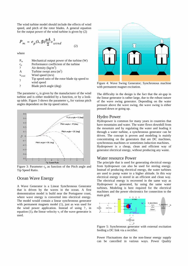
Ocean Wave Energy
A Wave Generator is a Linear Synchronous Generatorthat is driven by the waves in the ocean. A firstdemonstration model is build near the Portuguese coast,where wave energy is converted into electrical energy.The model would contain a linear synchronous generatorwith permanent magnets model (1), just as was used forthe wind power application. Instead of using ? r inequation (1), the linear velocity vr of the wave generator isused.
Figure 4: Wave Swing Generator; Synchronous machinewith permanent magnet excitation.
The difficulty in the design is the fact that the air-gap inthe linear generator is rather large, due to the robust natureof the wave swing generator. Depending on the waterpressure above the wave swing, the wave swing is eitherpressed down or going up.
Hydro PowerHydropower is common for many years in countries thathave mountains and water. The water flows downhill fromthe mountain and by regulating the water and leading itthrough a water turbine, a synchronous generator can bedriven. The concept is proven and modeling is mainlyconcentrating on the generators that are DC machines,synchronous machines or sometimes induction machines.Hydropower is a cheap, clean and efficient way ofgenerator electrical energy, without producing any waste.
Water resource PowerThe principle that is used for generating electrical energyfrom hydropower can also be used for storing energy.Instead of producing electrical energy, the water turbinesare used to pump water to a higher altitude. In this wayelectrical energy is stored in an efficient and clean way.The electrical energy is recovered in the same way asHydropower is generated, by using the same waterturbines. Modeling is here required for the electricalmachines and the power electronics for connection to themain grid.
C1 1m R1 5
B61 SYNE1
V1 100
+
-
R_BEARING1
500m
C_INERTIA2
100m
0
W
0
Figure 5: Synchronous generator with external excitationfeeding a DC link via a rectifier.
Power Fluctuations due to the non-linear energy supplycan be cancelled in various ways. Power Quality

Compensators for FACTS and Custom Power can be usedand in figure 6 a control system is shown that cancelspower fluctuations in a grid. The energy level is keptconstant by the controlled voltage source that in reality isa voltage source inverter supplied from a DC link.
Figure 6: Canceling Power Fluctuations. The grid ismodeled as a single phase in Caspoc[1].
To cancel out these power fluctuation, energy recoursesare required that can react very fast. Super capacitor banksare a new way of providing this energy.
Super CapacitorsSuper Capacitors or Electrochemical Double LayerCapacitors (EDLC) take advantage of the charge stored inthe Electro-chemical double layer and provide extremelyhigh capacities of more than 1000 Farads. These deviceshave applications in computer power back up, powerelectronics, electric vehicles and space flight technology.However, power and energy demands of theseapplications vary significantly.Special low resistance, high-power super capacitors,suitable for applications such as switch gear or powerquality are in development. Electrochemically modifiedglassy carbon is a promising material to be used inelectrochemical capacitors. Oxidation of the surface of aglassy carbon electrode results in a porous layer with verylarge capacitance and fairly low internal resistance whenusing an aqueous electrolyte.
Figure 7: Super-capacitor for 5.7kW and an energy levelof 115Joule.
In figure 7 a 24 V bipolar aqueous capacitor with amaximum power of 5.7 kW and a maximum energy of115 J is shown. The characteristic data are given below:
Nominal Voltage 24 VCapacitance 0.4 FESR 25 mohm @ 1 kHzRC Time-constant 10 msMax. Energy 115 JMax. Power 5.7 kW
One of the advantages of EDLCs is the cycle stability.With a 5V bipolar capacitor (5 cells) more than 100'000charge/discharge cycles between 0 V and 5 V weredemonstrated. During this cycle test, which lasted twomonths, the internal resistance as well as the capacitancechanged less than 10%. The Simulation of the SuperCapacitor shows the difference between discharge via theload and self discharge.
SCOPE1
R2 10
SUPERCAP2
SUPERCAP1
R1 1meg
0
0
Figure 8: Simulation of the discharge in a resistive load of10 ohms (upper schematic) and self-discharge (lowerschematic).
The model for the Super Capacitor is given below.
C1 0.4Farad RDIS 1000
LSERIES
10uH
RSERIES
25m
PLUS(Positive Capacitor connection)
MINUS(Negative Capacitor connection)
Figure 9: Equivalent circuit model for the SuperCapacitor.
Here the capacitance of the Super Capacitor is modeled byC1, while RDIS models the self-discharge of thecapacitor. The components Lseries and Rseries model theseries impedance of the capacitor. For automotiveapplications and also in high power applications, SuperCapacitors are connected in series and in parallel to gethigher power levels.
Figure 10: Super Capacitor bank for automotiveapplications
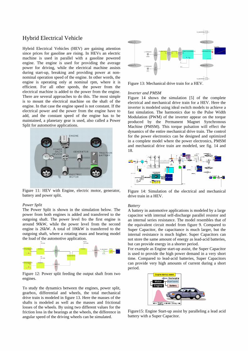
Hybrid Electrical Vehicle
Hybrid Electrical Vehicles (HEV) are gaining attentionsince prices for gasoline are rising. In HEVs an electricmachine is used in parallel with a gasoline poweredengine. The engine is used for providing the averagepower for driving, while the electrical machine assistsduring start-up, breaking and providing power at non-nominal operation speed of the engine. In other words, theengine is operating only at nominal rpm, where it isefficient. For all other speeds, the power from theelectrical machine is added to the power from the engine.There are several approaches to do this. The most simpleis to mount the electrical machine on the shaft of theengine. In that case the engine speed is not constant. If theelectrical power and the power from the engine have toadd, and the constant speed of the engine has to bemaintained, a planetary gear is used, also called a PowerSplit for automotive applications.
Figure 11: HEV with Engine, electric motor, generator,battery and power split.
Power SplitThe Power Split is shown in the simulation below. Thepower from both engines is added and transferred to theoutgoing shaft. The power level fro the first engine isaround 90kW, while the power level from the secondengine is 26kW. A total of 106kW is transferred to theoutgoing shaft, where a rotating mass and bearing modelthe load of the automotive application.
PLANETARY21
C_INERTIA1
200
POWER3POWER1
POWER2
C_INERTIA2
0.1
C_INERTIA3
0.1
R_BEARING1
0.01
R2T1 SCOPE1
POWERSOURCE2
POWERSOURCE1
POUTP1
P2
105.408k 79.644k
26.184k
Figure 12: Power split feeding the output shaft from twoengines.
To study the dynamics between the engines, power split,gearbox, differential and wheels, the total mechanicaldrive train is modeled in figure 13. Here the masses of theshafts is modeled as well as the masses and frictionallosses of the wheels. By using two different values for thefriction loss in the bearings at the wheels, the difference inangular speed of the driving wheels can be simulated.
CWHEEL2 1
CWHEEL1 1
SCOPE1
R_BEARING2 1
CWHEEL4 1
CWHEEL3 1
R_BEARING1 2
CLUTCH1 AUTOMATICGEARBOX1 DIFFERENTIAL1
T
I_TORQUE1
1000
PLANETARY21C1
100m
C2
10m T
I_TORQUE2
100
C_INERTIA1
1
C_INERTIA2
1
1
0.1
Figure 13: Mechanical drive train for a HEV.
Inverter and PMSMFigure 14 shows the simulation [5] of the completeelectrical and mechanical drive train for a HEV. Here theinverter is modeled using ideal switch models to achieve afast simulation. The harmonics due to the Pulse WidthModulation (PWM) of the inverter appear on the torqueproduced by the Permanent Magnet SynchronousMachine (PMSM). This torque pulsation will effect thedynamics of the entire mechanical drive train. The controlfor the power electronics can be designed and optimizedin a complete model where the power electronics, PMSMand mechanical drive train are modeled, see fig. 14 and18.
Figure 14: Simulation of the electrical and mechanicaldrive train in a HEV.
BatteryA battery in automotive applications is modeled by a largecapacitor with internal self-discharge parallel resistor andan internal series resistance. The model resembles that ofthe equivalent circuit model from figure 9. Compared toSuper Capacitor, the capacitance is much larger, but theinternal resistance is much higher. Super Capacitors cannot store the same amount of energy as lead-acid batteries,but can provide energy in a shorter period.For example as Engine start-up assist, the Super Capacitoris used to provide the high power demand in a very shorttime. Compared to lead-acid batteries, Super Capacitorscan provide very high amounts of current during a shortperiod.
Figure15: Engine Start-up assist by paralleling a lead acidbattery with a Super Capacitor.

Fuel Cell
Fuel cells generate power through an electrochemicalprocess, much like a battery. They convert chemicalenergy to electrical energy by combining hydrogen fromfuel with oxygen from the air. Hydrogen fuel can besupplied in two ways - either directly as pure hydrogengas or through a "fuel reformer" that convertshydrocarbon fuels such as methanol, natural gas, orgasoline into hydrogen-rich gas.
Figure 16: Fuel cells with two electrodes and electrolyte.
The quantitative evaluation of a galvanic power sourcecan be made in several ways, including cell voltage atfixed discharge current density, energy density, powerdensity, or discharge capacity. A common way to expressthe performance of a fuel cell is the steady-state voltageversus current (or current density), viz. polarization curve.
Figure 17: Voltage-Current relation for a Fuel Cell.
The Voltage-Current relation for a Fuel Cell is modeledby a non-linear voltage source that is current dependent.
References[1] Bauer P. Understanding the Power Quality Problems and
Compensators, Proceedings PCIM 2004, page 503-508, ISBN 3-928643-39-8
[2] Sasaki S., Sato E., Okamura M., The motor Control Technologiesfor the Hybrid Electric Vehicle, PCIM 2004, page 1-10, ISBN 3-928643-39-8
[3] Bauer P., Gospodaric D., Hybrid Electric Car Design andSimulation., Power Systems Design Europe, 7/8-2005,www.powersystemsdesigns.com, ISSN 16136365
[4] Bauer P., Duijsen P.J. van, Simulation Software with OpenInterface, Power Electronics Europe, page 29-31,
[5] Simulation Research, Simulation program Caspoc 2005,www.caspoc.com
Figure 18: Simulation in Caspoc [3] of the electric and mechanical drive train in a Hybrid Electrical Vehicle.