model hd-p8000 planetary winch - aw direct · consult the wire rope manufacturer for wire rope...
TRANSCRIPT

OPERATING, SERVICE ANDMAINTENANCE MANUAL
MODEL HD-P8000PLANETARY WINCH
CAUTION: READ AND UNDERSTAND THIS MANUAL BEFORE INSTALLATION ANDOPERATION OF WINCH. SEE WARNINGS!

TABLE OF CONTENTS
INTRODUCTIONS . . . . . . . . . . . . . . . . . . . . . . . . . . . . . . . . . . . . . . . . . . . . . . . . . . . . . . . . . . . . . . . .1
WARRANTY INFORMATION . . . . . . . . . . . . . . . . . . . . . . . . . . . . . . . . . . . . . . . . . . . . . . . . . . . . . . . .1
SPECIFICATIONS . . . . . . . . . . . . . . . . . . . . . . . . . . . . . . . . . . . . . . . . . . . . . . . . . . . . . . . . . . . . . . . .1
WARNINGS . . . . . . . . . . . . . . . . . . . . . . . . . . . . . . . . . . . . . . . . . . . . . . . . . . . . . . . . . . . . . . . . . . . .1
WINCH MOUNTING . . . . . . . . . . . . . . . . . . . . . . . . . . . . . . . . . . . . . . . . . . . . . . . . . . . . . . . . . . . . . .2
CABLE INSTALLATION . . . . . . . . . . . . . . . . . . . . . . . . . . . . . . . . . . . . . . . . . . . . . . . . . . . . . . . . . . . .3
HYDRAULIC SYSTEM REQUIREMENTS . . . . . . . . . . . . . . . . . . . . . . . . . . . . . . . . . . . . . . . . . . . . . . .4
TYPICAL LAYOUT . . . . . . . . . . . . . . . . . . . . . . . . . . . . . . . . . . . . . . . . . . . . . . . . . . . . . . . . . . . . . . .4
PERFORMANCE CHARTS . . . . . . . . . . . . . . . . . . . . . . . . . . . . . . . . . . . . . . . . . . . . . . . . . . . . . . . . .4
OPERATION . . . . . . . . . . . . . . . . . . . . . . . . . . . . . . . . . . . . . . . . . . . . . . . . . . . . . . . . . . . . . . . . . . . .5
MAINTENANCE . . . . . . . . . . . . . . . . . . . . . . . . . . . . . . . . . . . . . . . . . . . . . . . . . . . . . . . . . . . . . . . . .5
TROUBLE SHOOTING GUIDE . . . . . . . . . . . . . . . . . . . . . . . . . . . . . . . . . . . . . . . . . . . . . . . . . . . . . . .6
OVERHAUL INSTRUCTIONS . . . . . . . . . . . . . . . . . . . . . . . . . . . . . . . . . . . . . . . . . . . . . . . . . . . . .7-12
DIMENSIONAL DRAWINGS . . . . . . . . . . . . . . . . . . . . . . . . . . . . . . . . . . . . . . . . . . . . . . . . . . . . .14-15
PARTS LIST AND PARTS DRAWINGS . . . . . . . . . . . . . . . . . . . . . . . . . . . . . . . . . . . . . . . . . . . . .16-19
LIMITED WARRANTY . . . . . . . . . . . . . . . . . . . . . . . . . . . . . . . . . . . . . . . . . . . . . . . . . . .BACK COVER

PLEASE READ THIS MANUAL CAREFULLYThis manual contains useful ideas for obtaining the most efficient operation from your Ramsey Winch, and safety proceduresone needs to know before operating a Ramsey Winch. Do not operate this winch until you have carefully read and understandthe "WARNING" and "OPERATION" sections of this manual.
WARRANTY INFORMATIONRamsey Winches are designed and built to exacting specifications. Great care and skill go into every winch we make. If theneed should arise, warranty procedure is outlined on the back of your self-addressed postage paid warranty card. Please readand fill out the enclosed warranty card and send it to Ramsey Winch Company. If you have any problems with your winch,please follow instructions for prompt service on all warranty claims. Refer to back page for limited warranty.
SPECIFICATIONS*
NOTE: The rated line pulls shown are for the winch only. Consult the wire rope manufacturer for wire rope ratings.
WARNINGS:A MOTOR SPOOL (OPEN CENTER) DIRECTIONAL CONTROL VALVE IS REQUIRED FOR BRAKE OPERATION.
CLUTCH MUST BE FULLY ENGAGED BEFORE STARTING THE WINCH.
DO NOT DISENGAGE CLUTCH UNDER LOAD.
DO NOT LEAVE CLUTCH ENGAGED WHEN WINCH IS NOT IN USE.
STAY OUT FROM UNDER AND AWAY FROM RAISED LOADS.
STAND CLEAR OF CABLE WHILE PULLING. DO NOT TRY TO GUIDE CABLE.
DO NOT EXCEED MAXIMUM LINE PULL RATINGS SHOWN IN TABLE.
DO NOT USE WINCH TO LIFT, SUPPORT, OR OTHERWISE TRANSPORT PERSONNEL.
A MINIMUM OF 5 WRAPS OF CABLE AROUND THE DRUM BARREL IS NECESSARY TO HOLD THE LOAD. CABLE CLAMP(SETSCREW) IS NOT DESIGNED TO HOLD LOAD.
IN CAR CARRIER APPLICATIONS, AFTER PULLING VEHICLE ON CARRIER, BE SURE TO SECURE VEHICLE TO CARRIERBED. DO NOT MAINTAIN LOAD ON WINCH CABLE WHILE TRANSPORTING VEHICLE. DO NOT USE WINCH AS A TIEDOWN.
WHEN PULLING A HEAVY LOAD PLACE A BLANKET, JACKET, OR TARPAULIN OVER THE CABLE FIVE OR SIX FEET FROMTHE HOOK.
AVOID CONDITIONS WHERE LOAD SHIFTS OR JERKS OCCUR, AS THEY MAY INDICATE A DANGEROUS SITUATION.
1
Rated Line Pull (lbs.) ………………………………………………… 8,000
(Kg.) ………………………………………………… 3,620
Gear Reduction 5.1:1
HD-P8000 STD. ……..…....……….82 lbs. (37.2 Kg)
HD-P8000 "Y" ………….…………..76 lbs. (34.5 Kg)
1 2 3 4 5
lbs. 8,000 6,800 5,900 5,200 4,700
Kg. 3,620 3,080 2,670 2,350 2,120
ft. 25 55 90 130 170
m 7 16 27 39 51
ft. 15 35 60 85 115
m 4 10 18 25 34
FPM 50 58 67 76 84
MPM 15.2 17.6 20.3 23.1 25.5
…………………………………………………………
Weight (without cable)
* These specifications are based on recommended wire rope of 3/8" (10mm)
galvanized aircraft cable, or EIPS cable and a 14.9 cu.in./Rev. motor.
LAYER OF CABLE
*Rated line pull
per layer
HD-P8000 (STD.
DRUM)
* Line Speed (at
15 GPM)
HD-P8000 ("Y"
DRUM)
* Cable Capacity per Layer

WINCH MOUNTING
ESSENTIAL MOUNTING INSTRUCTIONS TO MAINTAIN ALIGNMENT OF PLANETARY WINCH COMPONENTS:
It is most important that this winch be mounted securely so that the three major sections (the motor end, the cabledrum, and the gear housing end) are properly aligned. Excessive bushing wear and difficulty in freespooling are usu-ally symptoms of misalignment.
In the as-installed condition, if the winch is mid-mounted, then at least one tie-plate must be attached to the mountingfeet at the bottom of the winch to maintain alignment. If the winch is foot mounted then at least one tie-plate mustremain mounted at midpoint of winch to maintain alignment. It is always preferred to used BOTH tie-plates in the finalinstalled configuration.
Angle Mounting Kit, P/N 251006 (for Std. Drum) or 251007 (for “Y” drum), is recommended for maximum ease inmounting the winch. The angle kit will allow the winch to be mounted in upright or midmount applications and willmeet the criteria of serving as a solid and true mounting surface.
When mounting the winch with other than the recommended Ramsey Angle Kit, the mounting hole patterns describedin the Dimensional drawings on pages 14-15 should be used. The mounting surface must be flat within .015 inchand sufficiently stiff to resist flexing. If a steel plate is used for foot mounting, it should be .750 inch thick. For thismounting application eight (8) 1/2-13NC x 1-1/2” long grade 5 capscrews with lockwashers will be needed to mountwinch. Capscrews should be tightened to 55 ft-lb (75 Nm) torque.
NOTE: If angles or a steel plate are used in mounting winch, tie-plates provided with winch are to be attached to theremaining mounting pads, whether they be side or foot.
* CAUTION: If longer bolts (minimum grade 5) are substituted to mount winch or to mount a roller guide at theside mount pads, bolt length must be such as to allow a minimum of .50 inch thread length engagement in thetapped holes in side of each end bearing. Refer to pages 14-15. Use of excessive length bolts will damage thewinch and prevent freespool of the drum. Torque bolts to 55 ft-lbs. (75 Nm).
2
MOTOR END CABLE DRUMGEAR HOUSING END
TIEPLATE AT SIDE LOCATION
TIEPLATE AT FOOT (BASE) LOCATION
SEE BOLT LENGTH
CAUTION BELOW *
FOOT MOUNT
MID MOUNT

CABLE INSTALLATION
An “A” or “B” decal on the clutch end bearing indicates the spooling direction of the cable. Also, a letter “A” or “B” isstamped in the end bearing on the clutch end indicating rotation direction. If the decal is damaged or unreadable,contact Customer Service for additional instructions to determine proper direction. To reverse the rotation direc-tion, exchange positions of the cartridge and plug shown below.
1. Unwind cable by rolling it out along the ground to prevent kinking. Securely wrap end of cable, opposite hook,with plastic or similar tape to prevent fraying.
2. Place taped end of cable into hole in cable drum as shown below. Use the 3/8-16NC x 1/2” long hex socketdrive setscrew (included with drum assembly item #1) to secure cable to drum.
3. Carefully run winch in the "reel-in" direction. Keeping tension on end of cable, spool all the cable onto the cabledrum, taking care to form neatly wrapped layers.
After installing cable, check freespool operation. Disengage clutch and pull on cable at a walking speed. If cable“birdnests”, loosen jam nut (item #20) and turn nylon setscrew (item #17) clockwise to increase drag on drum. Ifcable pull is excessive, loosen nylon setscrew by turning counterclockwise. Tighten jam nut when proper setting isobtained. CAUTION: OVER-TIGHTENING OF JAM NUT MAY STRIP NYLON SETSCREW.
3
INSERT CABLE AS SHOWN FOR "A" ROTATION
OVERWOUND APPLICATION.
(UNDERWOUND APPLICATION REQUIRES CABLE TO
COME UNDER DRUM FROM OPPOSITE DIRECTION
AND INSERTED IN THIS SAME CABLE POCKET.)
INSERT CABLE AS SHOWN FOR "B" ROTATION
OVERWOUND APPLICATION.
(UNDERWOUND APPLICATION REQUIRES CABLE TO
COME UNDER DRUM FROM OPPOSITE DIRECTION
AND INSERTED IN THIS SAME CABLE POCKET.)
"B" ROTATION
DIRECTION
"A" ROTATION
DIRECTION
SETSCREW
17
20
PLUG
POSITION
CARTRIDGE
POSITION
CARTRIDGE
POSITION
CABLE DRUM
ROTATION DIRECTION
CABLE DRUM
ROTATION DIRECTION
"B" ROTATION"A" ROTATION
(REEL IN) RAISE INLET

HYDRAULIC SYSTEM REQUIREMENTS
Refer to the performance charts below to properly match your hydraulic system to the winch performance. Thecharts consist of:
(1) Line Pull first layer (lb.) vs. Working Pressure (PSI)
(2) Line Speed, first layer (FPM) vs. flow (GPM)
SYSTEM REQUIREMENTS
MOTOR SPOOL (OPEN CENTER) CONTROL VALVE REQUIRED
2500 PSI RELIEF VALVE SETTING
15 GPM FLOW RATE
DO NOT EXCEED 20 GPM--MOTOR AND WINCH MAY BE DAMAGED
10 MICRON NOMINAL FILTRATION
PORT CONTROL
PUMP
(.75 I.D. MINIMUM)LOW PRESSURE LINE(.50 I.D. MINIMUM)
HIGH PRESSURE LINE
2500 PSI15 GPMRATED LOAD:PRESSURE ATMAX. FLOW &
(MOTOR SPOOL)4 WAY VALVE3 POSITION
RELIEFSYSTEM
A
PORTBRAKE
MOTOR
WITH BRAKE RELEASE SHUTTLE
TYPICAL LAYOUT
B
4
LIN
E P
ULL
-FIR
ST
LA
YE
R (
LB
)
LIN
E S
PE
ED
-FIR
ST
LA
YE
R (
FP
M)
0 5 10 1510
20
30
40
0
0
1000
2000
3000
4000
5000
6000
7000
8000
1000 2000 2500
50
1500500
PERFORMANCE CHARTS

OPERATION
The best way to get acquainted with how your winch operates is to make test runs before you actually use it. Planyour test in advance. Remember, you hear your winch as well as see it operate. Get to recognize the sounds of a lightsteady pull, a heavy pull, and sounds caused by load jerking or shifting. Avoid conditions where load shifts or jerksoccur, as they may indicate a dangerous situation.
The uneven spooling of cable, while pulling the load, is not a problem, unless there is a cable pileup on one end ofthe drum. If this happens, reverse the winch to relieve the load, and move your anchor point further to the center ofthe vehicle. After the job is done you can unspool and rewind for a neat lay of the cable.
When pulling a heavy load, place a blanket, jacket, and tarpaulin over the cable about five or six feet behind the hook.In the event of a broken cable, this will slow the snap back of the cable and could prevent serious injury.
The winch clutch allows rapid unspooling of the cable, from the cable drum, for hooking onto the load. The clutch isoperated by the clutch shifter lever or air shifter.
WARNING: DO NOT DISENGAGE CLUTCH UNDER LOAD!
MANUAL CLUTCH SHIFTER (Refer to dimensional drawing page 14):
TO DISENGAGE CLUTCH: Run the winch in the reverse (reel out) direction until the load is off the cable. Pull handleout and rotate 90°. With handle in the “DISENGAGED” position, cable may now be free-spooled from the drum.
TO ENGAGE CLUTCH: Pull handle out, rotate 90° and release handle. Run the winch in reverse until the clutch handlesnaps fully into the “ENGAGED” position. DO NOT attempt to pull a load unless the handle is fully at the “ENGAGED”position. If manual shift indicator light is present, the green light is lit when clutch is fully “ENGAGED”. DO NOTattempt to pull a load unless the green light is lit. To install light to the vehicle electrical system refer to the ElectricalSchematic on page 15.
AIR CYLINDER CLUTCH SHIFTER (Refer to the dimensional drawing page 15):
TO DISENGAGE CLUTCH: Run the winch in the reverse (reel out) direction until load is off the cable. Apply air pres-sure to the .125-27 NPT port: 80 PSI (min.)-150 PSI (max.). CAUTION: PRESSURE MUST NOT EXCEED 150 PSI.
TO ENGAGE CLUTCH: Remove air pressure from the cylinder (a return spring engages the plunger). Run winch inreverse until the clutch engagement indicator light (green light) is lit. To install light to the vehicle electrical systemrefer to the Electrical Schematic on page 15.
MAINTENANCE
1. Inspect the cable for damage and lubricate frequently. If the cable becomes frayed with broken strands, replaceimmediately. Cable and hook assembly (100’ long cable) P/N 524118 (“Y” drum) or (150’ long cable) P/N524119 (STD drum) may be purchased from a Ramsey distributor.
2. Check that the clutch is fully engaging. See OPERATION instructions, above, for the appropriate clutch shifter.FOR MANUAL CLUTCH ONLY: Monthly, disengage clutch, put several drops of oil on the clutch handle shaft andwork clutch handle IN and OUT several times to lubricate inside the shifter assembly.
3. Check to see that the drum cable does not overrun (“birdnest”) when freespooling. Refer to page 3 if it does.
4. Replace drum bushings and seals if seals begin to seep grease. Refer to the Overhaul Instructions, pages 7-12.Add additional lubricant, Mobilith SHC 007, to gears and drum bearings if required.
5

CONDITIONS POSSIBLE CAUSE CORRECTION/ACTION
DRUM WILL NOT ROTATEAT NO LOAD
Winch not mounted squarely, causing end bearingto bind up
Check mounting. Refer to Winch Mounting, page 2.
Gears damaged Inspect and replace damaged gears
DRUM WILL NOT ROTATEUNDER LOAD
Winch not mounted squarely, causing end bearingto bind up
Check mounting. Refer to Winch Mounting, page 2.
Load greater than rated capacity of winch Refer to Specifications page 1 for line pull rating.
Low hydraulic system pressure Check pressure. Refer to Hydraulic Systems per-formance charts page 4.
WINCH RUNS TOO SLOW Low hydraulic system flow rate Check flow rate. Refer to Systerm Requirements andTypical Layout page 4.
Motor worn out Replace motor
DRUM WILL NOTFREESPOOL
Clutch not disengaged. Check Adjustment of ManualShifter, page 10.
Check Operation, page 5.
Winch not mounted squarely, causing end bearingto bind up
Check mounting. Refer to Winch Mounting, page 2.
Side mounted bolts too long, causing binding of ringgear (Item #15, page 16).
Check bolt length. Bolt thread MUST NOT engagethreaded holes in sides of end bearing more than the.50 inch thread depth in the end bearing.
BRAKE WILL NOT HOLD Incorrect directional control valve (cylinder spool-closed center)
Use only a motor spool (open center) control valve.
LOAD DRIFTS Excessive Backpressure (100 PSI Max.) Check for restrictions in hydraulic system. Refer toSystem Requirements and Typical Layout page 4.
CABLE BIRDNESTS WHENCLUTCH IS DISENGAGED
Drag screw improperly adjusted Adjust nylon drag screw. Refer to Cable Installation,page 3.
EXCESSIVE NOISE Hydraulic system flow too high Check flow rate. Refer to Typical Layout page 4.
Drum in bind, winch not mounted squarely Check mounting. Refer to Winch Mounting, page 2.
DRUM CHATTERS IN“REEL IN” DIRECTION
Low hydraulic system flow rate Check flow rate. Refer to Typical Layout page 4.
Low hydraulic system relief pressure setting Check relief valve setting.
OIL LEAKS FROMBREATHER VENT UNDERMOTOR END BEARING
Damaged brake o-rings, backup rings, or sealingsurfaces
Disassemble brake and inspect. See OverhaulInstructions, pg. 8.
TROUBLESHOOTING GUIDE
6

7
40
24
41 42 21
14
24
23
25
27
22
18
45
INSTRUCTIONS FOR OVERHAUL HD-P8000 SERIES WINCH
Take note of mounting configurations for proper mounting of parts during re-assembly. Replace all gas-kets, o-rings, and seals during re-assembly.
Disconnect tube (item #41) from elbow fittings (items #24) on bottom of end bearing and counterbalance valve(item #42). Remove motor (item #27) from end bearing by slowly unscrewing capscrews (items #18). CAUTION:MOTOR IS UNDER SPRING PRESSURE.
Check breather vent (item #45). Make sure it is not clogged. If oil is leaking from vent, check brake o-rings, backuprings, and sealing surfaces (see page 8).
Remove springs (items #40) from pockets and inspect for damage.
Replace gasket (item #25).
Remove coupling (item #23) from end bearing. Examine coupling for signs of wear, replace if necessary. If neces-sary, remove counterbalance valve from motor by removing capscrews (items #14).
8
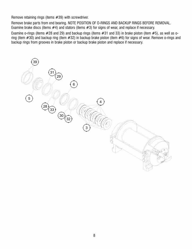
Remove retaining rings (items #39) with screwdriver.
Remove brake parts from end bearing. NOTE POSITION OF O-RINGS AND BACKUP RINGS BEFORE REMOVAL.Examine brake discs (items #4) and stators (items #3) for signs of wear, and replace if necessary.
Examine o-rings (items #28 and 29) and backup rings (items #31 and 33) in brake piston (item #5), as well as o-ring (item #30) and backup ring (item #32) in backup brake piston (item #6) for signs of wear. Remove o-rings andbackup rings from grooves in brake piston or backup brake piston and replace if necessary.
4
3
3230
6
2833
2931
5
39

9
Remove tie plates (items #11) from end bearings by unscrewing capscrews (items #15). Slide motor end bearing(item #8) and drum (item #1) from gear housing end bearing.
Remove input shaft (item #10) from end bearing. Inspect shaft and and output sun gear (item #7) for damage andreplace if necessary. To remove the output sun gear, remove the snap rings (items #38) and thrust washer (item#44) and pull off the end of the shaft.
Remove bushing (item #13) and o-ring (item #34) from motor end bearing. Place new, well-oiled o-ring into grooveinside of end bearing and press new bushing onto end bearing.
13
34
8
38
44
7
101
11
15
11
15
Remove seal (item #37) from gear housing end bearing (item#9). Loosen nut (item #20) and remove nylon setscrew (item#17). Remove ring gear from gear housing end bearing, if nec-essary. Remove bushing (item #12) from end bearing.
Press new bushing into end bearing. Install ring gear, thennylon setscrew and nut. Ring gear must be fully seated in endbearing and slot in ring gear MUST NOT be aligned with clutchshifter hole. Install new seal in end bearing, with sharp edge ofseal outward.
12 9
26
37
2017

10
Generously apply grease (MOBILITH SHC 007) to teeth of ring gear (item #26), teeth of planet gears in drum (item #1), and tobushing (item #12) in gear housing end bearing. Apply a small amount of grease to base of bushing (item #13) on motor endbearing. Apply grease to teeth of output sun gear (item #7) and input shaft (item #10).
Place end of shaft with output sun gear on it into drum (item #2). Rotate shaft to engage planet gears with output sun gear.Place Gear End Bearing on Drum and engage planet gears with ring gear.
Assemble motor end bearing (item #8) to drum assembly and use tie plates (items #11) and capscrews (items #15) to holdboth end bearings together. Tighten capscrews to 55 ft-lbs (75 Nm).
If necessary, remove and replace the shifter assembly (manual, item #2, or air-cylinder, item #3), as follows:
MANUAL CLUTCH SHIFTER ASSEMBLY
Loosen setscrew (item #19) and jam nut, then unscrew shifter assembly (item #2). Be sure slot in ring gear is not aligned withclutch shifter hole. Rotate drum, if necessary, to ensure hole and slot are not aligned.
Reinstall shifter assembly with plunger, jam nut, and handle positioned in gear housing as shown below. Thread assembly (withhandle engaged in cylinder slot) into the gear housing. Pull drum toward the gear end bearing housing to remove play. Holddrum in position and continue threading the shifter assembly in until the gap between the end of the handle and cylinder is
7/16 +0-1/16 inch and handle is in the horizontal position (see below). Note: This gap will vary with drum endplay. With the
drum pulled against the motor end housing, the gap should be 3/8 inch.
Lightly tighten jam nut. Rotate drum until handle snaps fully into the engaged position. Pull handle out and rotate 90°. Verify thatdrum can be rotated freely (at least one full revolution) with clutch shifter at the DISENGAGED position. Securely tighten jam nutwhile holding the handle. Tighten setscrew (item #19) securely. Re-check clutch operation as described on page 5.
AIR CYLINDER SHIFTER ASSEMBLY
Loosen set screw (item #19) to remove shifter assembly (item #3). To reinstall, place 1 or 2 shims (items #41) over plungerand thread shifter assembly into gear end housing. Add or remove shims to orient ports for pneumatic connections. Portsshould point down (below horizontal). Tighten setscrew. Check for clutch operation as described on page 5.
If the light assembly (item #2) or light switch (item #45) needs to be replaced, refer to the schematic on page 15 for electricalconnections and disassemble and reassemble as shown below.
38
45LIGHT SWITCH
LIGHT ASSEMBLY
JAM NUT
PLUNGER
AIR-CYLINDER
CLUTCH SHIFTER
MANUAL CLUTCH
SHIFTER
MANUAL CLUTCH ADJUSTMENT
HANDLE (HORIZONTAL)
CYLINDER
16
4
39
2
3
41
16
2
19
9

11
Set winch with gear housing end down on work surface.
Install well-oiled o-rings and backup rings into grooves on outside of brake piston and backup brake piston as shownin cross-section A-A below.
Piston, backup piston, brake discs and stators must be clean and free of grease and oil.
Insert brake discs (item #4) and stators (item #3) into gear end alternating, with stators first and last.
Insert backup brake piston (item #6) into motor end and insert brake piston (item #5) into it. Apply even pressureon piston when installing.
Install retaining rings (item #39) into grooves in motor end housing.
DRUM SIDE
MOTOR SIDE
33
28
32302931
65
SECTION A-A
A
A4
3
3230
6
2833
2931
5
39

12
Insert springs (item #40) into pockets in back of brake piston. The two empty pockets should be on opposite sides.
Install roll pin (item #35) into new motor coupling below bottom of spline teeth. Insert motor coupling (item#23), engaging it with the discs and the input shaft.
Place gasket (item #25) on mounting surface of motor (item #27). Slide motor shaft into coupling. Attach motor tomotor end bearing housing using (2) capscrews (item #18) and (2) lockwashers (item #22). Evenly tighten to 49 ft-lbs. (66 Nm) torque.
Install the counterbalance valve (item #42) to the motor using (4) capscrews (item #14) and (4) lockwashers (item#21). Tighten to 17 ft-lbs (23 Nm).
Securely connect fittings (item #24) to motor end housing and counterbalance valve, and connect tube assembly(item #41) to fittings.
Apply at least 550 PSI hydraulic system pressure to brake and verify that brake releases (winch drum will rotate).
35
45
40
24
41 42 21
14
24
23
25
27
22
18

13
NOTES

14
2.2
1
[56.1
]
Ø8.2
5
[209.6
].5
6
[14.3
]
8.3
8
[212.7
]2.2
5
[57.2
]
4.1
9
[106.4
]
3.7
9
[96.3
]
7.1
7
[182.1
]Ø
.50
[Ø
12.7
]
1.2
5
[31.7
].5
0
[12.7
]
2.2
1
[56.1
]
4.2
5
[108.0
]
MM
INC
HE
SF
27
.89
70
8,3
24
.64
62
5.8
F
ED
C
B
A
"Y"
DR
UM
ST
D. D
RU
M
29
6,2
11
.66
33
7,4
13
.28
32
9,6
12
.98
37
0,9
14
.60
EIN
CH
ES
MM
DIN
CH
ES
MM
WIN
CH
MO
DE
L
HD
-P8
00
0
HD
-P8
00
0
INC
HE
SM
MA
MM
INC
HE
SB
MM
INC
HE
SC
9.7
52
47
,7
6.5
01
65
,1
12
.25
31
1,2
9.0
02
28
,6
8.8
72
25
,3
7.2
41
84
,0
CA
BLE
AN
CH
OR
4.9
2
[125.0
]8.4
6
[214.9
]
(2-P
LA
CE
S E
AC
H S
IDE
OF
GE
AR
HO
US
ING
EN
D B
EA
RIN
G)
1/2
-13U
NC
X .50 (
INC
HE
S)
DE
EP
TA
PP
ED
HO
LE
7/8
-14 S
AE
PO
RT
(2-P
LA
CE
S)
1/2
-13U
NC
X .75 (
INC
HE
S)
DE
EP
TA
PP
ED
HO
LE
(2-P
LA
CE
S E
AC
H S
IDE
OF
MO
TO
R E
ND
BE
AR
ING
)
DR
UM
BA
RR
EL
Ø3.9
4
[100.0
]
FLA
NG
E
8.3
8
[212.9
]
9.3
6
[237.7
]4.6
8
[118.9
]
(TY
P)
(TY
P)
(TY
P)
(TY
P)
1.1
2
[28.4
]
1.1
2
[28.4
]
NO
TE
S:
1. D
IME
NS
ION
S S
HO
WN
AR
E IN
CH
ES
OV
ER
MIL
LIM
ET
ER
S.
2. W
INC
H M
OU
NT
ING
CA
PS
CR
EW
S M
US
T M
EE
T O
R E
XC
EE
D S
AE
GR
AD
E 5
SP
EC
IFIC
AT
ION
.
3. T
HE
SE
HO
LE
LO
CA
TIO
NS
MU
ST
BE
HE
LD
WIT
HIN
±.0
3 (
0.8
mm
)
O
F T
RU
E P
OS
ITIO
N. R
EC
OM
ME
ND
ED
MO
UN
TIN
G H
OLE
DIA
ME
TE
R IS
.53 (
13.5
mm
).
4. "A
" R
OT
AT
ION
SH
OW
N.
CLU
TC
H D
ISE
NG
AG
ED
PO
SIT
ION
CLU
TC
H E
NG
AG
ED
PO
SIT
ION
1/2
-13U
NC
X .75 (
INC
HE
S)
DE
EP
TA
PP
ED
HO
LE
(4-P
LA
CE
S E
AC
H E
ND
BE
AR
ING
)
MO
VE
TIE
PLA
TE
S T
O F
EE
TF
OR
SID
E M
OU
NT
IN
ST
ALLA
TIO
NS
,
HD
-P80
00 M
ANUA
L SH
IFT

Ø.5
0
[Ø
12.7
]
Ø8.2
5
[209.6
]
3.7
9
[96.3
]
2.2
1
[56.1
]
4.2
5
[108.0
]
4.1
9
[106.4
]
2.2
5
[57.2
]
8.3
8
[212.7
]
.56
[14.3
]
2.2
1
[56.1
]
3.5
6
[90.5
]1.2
5
[31.7
]
F
ED
C
B
A
184
,07
.24
225
,38
.87
228
,69
.00
311
,21
2.2
5
165
,16
.50
247
,79
.75
CIN
CH
ES
MM
BIN
CH
ES
MM
A
MM
INC
HE
S
HD
-P8
000
HD
-P8
000
MO
DE
LW
INC
H
MM
INC
HE
SD
MM
INC
HE
SE
14.6
03
70
,9
12.9
83
29
,6
12.7
23
23
,1
9.4
72
40
,6
ST
D. D
RU
M
"Y"
DR
UM
611
,12
4.0
6
693
,72
7.3
1
FIN
CH
ES
MM
EN
GA
GE
D A
ND
"O
FF
" W
HE
N C
LU
TC
H IS
DIS
EN
GA
GE
D.
NO
TE
: LIG
HT
SH
OU
LD
BE
"O
N"
WH
EN
CLU
TC
H IS
RE
CE
IVE
12V
DC
WH
EN
PT
O IS
EN
GA
GE
D.
AT
TA
CH
TO
PT
O IN
DIC
AT
OR
SW
ITC
H T
O
SC
HE
MA
TIC
ELE
CT
RIC
AL
WIR
E S
UP
PLIE
D B
Y C
US
TO
ME
R)
AT
TA
CH
TO
GR
OU
ND
(16 G
A.
CO
NN
EC
TO
RB
UT
T
SW
ITC
H
IS E
NG
AG
ED
)(O
N W
HE
N C
LU
TC
HIN
DIC
AT
OR
LIG
HT
12V
BA
TT
ER
Y
SW
ITC
H
IND
ICA
TO
R
LIG
HT
1/8
-27N
PT
PO
RT
(CO
NN
EC
T 8
0 T
O 1
50 P
SI*
*
PR
ES
SU
RE
LIN
E T
O D
ISE
NG
AG
E C
LU
TC
H)
AT
TA
CH
TO
GR
OU
ND
(-)
(SE
E E
LE
CT
RIC
AL S
CH
EM
AT
IC)
AT
TA
CH
TO
12V
DC
(+
)
(SE
E E
LE
CT
RIC
AL S
CH
EM
AT
IC)
CA
BLE
AN
CH
OR
4.9
2
[125.0
]8.4
6
[214.9
]
(2-P
LA
CE
S E
AC
H S
IDE
OF
GE
AR
HO
US
ING
EN
D B
EA
RIN
G)
1/2
-13U
NC
X .50 (
INC
HE
S)
DE
EP
TA
PP
ED
HO
LE
7/8
-14 S
AE
PO
RT
(2-P
LA
CE
S)
1/2
-13U
NC
X .75 (
INC
HE
S)
DE
EP
TA
PP
ED
HO
LE
(2-P
LA
CE
S E
AC
H S
IDE
OF
MO
TO
R E
ND
BE
AR
ING
)
DR
UM
BA
RR
EL
Ø3.9
4
[100.0
]
FLA
NG
E
8.3
8
[212.9
]
9.3
6
[237.7
]4.6
8
[118.9
]
(TY
P)
(TY
P)
(TY
P)
(TY
P)
1.1
2
[28.4
]
1.1
2
[28.4
]
NO
TE
S:
1. D
IME
NS
ION
S S
HO
WN
AR
E IN
CH
ES
OV
ER
MIL
LIM
ET
ER
S.
2. W
INC
H M
OU
NT
ING
CA
PS
CR
EW
S M
US
T M
EE
T O
R E
XC
EE
D S
AE
GR
AD
E 5
SP
EC
IFIC
AT
ION
.
3. T
HE
SE
HO
LE
LO
CA
TIO
NS
MU
ST
BE
HE
LD
WIT
HIN
±.0
3 (
0.8
mm
)
O
F T
RU
E P
OS
ITIO
N. R
EC
OM
ME
ND
ED
MO
UN
TIN
G H
OLE
DIA
ME
TE
R IS
.53 (
13.5
mm
).
4. C
AU
TIO
N: P
RE
SS
UR
E M
US
T N
OT
EX
CE
ED
150 P
SI.
5. "A
" R
OT
AT
ION
SH
OW
N.
1/2
-13U
NC
X .75 (
INC
HE
S)
DE
EP
TA
PP
ED
HO
LE
(4-P
LA
CE
S E
AC
H E
ND
BE
AR
ING
)
MO
VE
TIE
PLA
TE
S T
O F
EE
TF
OR
SID
E M
OU
NT
IN
ST
ALLA
TIO
NS
,
HD
-P80
00 A
IR S
HIF
T
15

40
24
24
41
1
12
10
44
38
7
26
37
15
11
43
36
16
2
19
20
17
15
11
13
34
4
3
32
30
6
28
33
29
31
5
39
23
25
35
27
22
18 42
21 14
8
9
45
16
Item
No
.Q
uan
tity
Part
No
.D
escri
pti
on
Item
No
.Q
uan
tity
Part
No
.D
escri
pti
on
11
234205
DR
UM
AS
SY
ST
D23
1431019
CO
UP
LIN
G-M
OT
OR
1234204
DR
UM
AS
SY
"Y
"24
2432018
FIT
TIN
G
21
276048
SH
IFT
ER
AS
SY
25
1442223
GA
SK
ET
-MO
TO
R F
LA
NG
E
36
330011
ST
AT
OR
-BR
AK
E26
1444084
GE
AR
-RIN
G
45
330012
DIS
C-B
RA
KE
27
1458074
MO
TO
R-H
YD
.
51
330013
PIS
TO
N-B
RA
KE
28
1462067
O-R
ING
PIS
TO
N-S
M.
61
330014
PIS
TO
N-B
AC
KU
P B
RA
KE
29
1462068
O-R
ING
PIS
TO
N-L
G.
71
334174
GE
AR
-OU
TP
UT
, S
UN
30
1462069
O-R
ING
BA
CK
UP
PIS
TO
N
81
338358
EN
D B
EA
RIN
G-M
OT
OR
31
1462070
RIN
G-B
AC
KU
P P
IST
ON
-LG
91
338359
EN
D B
EA
RIN
G-G
EA
R H
OU
SIN
G32
1462071
RIN
G-B
AC
KU
P B
AC
KU
P P
IST
ON
10
1357177
SH
AF
T-I
NP
UT
ST
D D
RU
M33
1462072
RIN
G-B
AC
KU
P P
IST
ON
-SM
1357176
SH
AF
T-I
NP
UT
"Y
" D
RU
M34
1462073
O-R
ING
11
2395427
PLA
TE
-TIE
ST
D D
RU
M35
1470033
SP
IRO
L P
IN
2395426
PLA
TE
-TIE
"Y
" D
RU
M36
1472052
PLU
G
12
1412085
BU
SH
ING
-DR
UM
37
1486080
SE
AL
13
1412109
BU
SH
ING
-DR
UM
, M
OT
OR
EN
D38
2490003
SN
AP
RIN
G
14
4414159
CA
PS
CR
EW
-5/1
6-1
8U
NC
X 2
1/2
", H
EX
HE
AD
, Z
INC
, G
R5
39
2490049
RIN
G-I
NT
ER
NA
L R
ET
AIN
ING
15
8414581
CA
PS
CR
EW
-1/2
-13N
C X
3/4
", H
EX
HE
AD
, Z
INC
, G
R5
40
9494124
SP
RIN
G-B
RA
KE
16
2414854
SC
RE
W-1
/4-2
0N
C X
1/2
", R
OU
ND
HE
AD
, S
LO
TT
ED
, Z
INC
41
1509132
TU
BE
-BR
AK
E R
ELE
AS
E (
PO
RT
S D
OW
N)
17
1414926
SE
TS
CR
EW
-3/8
-16N
C X
1",
SO
CK
ET
HE
AD
, N
YLO
N1
509131
TU
BE
-BR
AK
E R
ELE
AS
E (
PO
RT
S U
P)
18
2414952
CA
PS
CR
EW
-1/2
-13N
C X
1 1
/2",
SO
CK
ET
HE
AD
, Z
INC
42
1516041
VA
LV
E-M
OT
OR
CO
NT
RO
L (
A R
OT
AT
ION
)
19
1416016
SE
TS
CR
EW
-1/4
-20N
C X
1/4
", H
EX
SO
CK
ET
HE
AD
CU
P1
516042
VA
LV
E-M
OT
OR
CO
NT
RO
L (
B R
OT
AT
ION
)
20
1418036
NU
T-3
/8-1
6 N
C, H
EX
JA
M, Z
INC
43
1518037
TH
RU
ST
WA
SH
ER
21
4418163
LO
CK
WA
SH
ER
-5/1
6 M
ED
SE
CT
, Z
INC
44
1518047
TH
RU
ST
WA
SH
ER
22
2418218
LO
CK
WA
SH
ER
-1/2
ID
ME
D S
EC
T, Z
INC
45
1456038
BR
EA
TH
ER
VE
NT
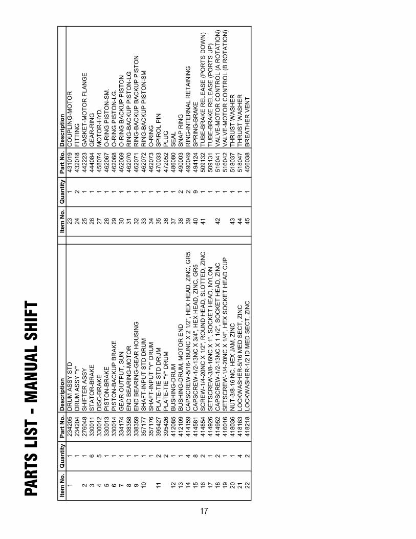
PART
S LI
ST -
MAN
UAL
SHIF
T
17

18
24
24
41
1
14
12
48
42
9
28
40
18
13
45
38
21
22
19
18
13
15
36
6
5
34
32
8
30
35
31
33
7
44
43
25
27
37
29
24
20 47
23 17
16
4
39
2
3
41
11
10
49

Ite
m N
o.
Qu
an
tity
Part
No
.D
escri
pti
on
Item
No
.Q
uan
tity
Part
No
.D
escri
pti
on
11
234205
DR
UM
AS
SY
ST
D25
1431019
CO
UP
LIN
G-M
OT
OR
1234204
DR
UM
AS
SY
"Y
"26
2432018
FIT
TIN
G
21
236020
LIG
HT
AS
SY
27
1442223
GA
SK
ET
-MO
TO
R F
LA
NG
E
31
276058
SH
IFT
ER
AS
SY
28
1444084
GE
AR
-RIN
G
41
312529
BR
AC
KE
T -
LIG
HT
AS
SY
29
1458074
MO
TO
R-H
YD
.
56
330011
ST
AT
OR
-BR
AK
E30
1462067
O-R
ING
PIS
TO
N-S
M.
65
330012
DIS
C-B
RA
KE
31
1462068
O-R
ING
PIS
TO
N-L
G
71
330013
PIS
TO
N-B
RA
KE
32
1462069
O-R
ING
BA
CK
UP
PIS
TO
N
81
330014
PIS
TO
N-B
AC
KU
P B
RA
KE
33
14
62070
RIN
G-B
AC
KU
P P
IST
ON
-LG
91
334174
GE
AR
-OU
TP
UT
, S
UN
34
1462071
RIN
G-B
AC
KU
P B
AC
KU
P P
IST
ON
10
1338358
EN
D B
EA
RIN
G-M
OT
OR
35
1462072
RIN
G-B
AC
KU
P P
IST
ON
-SM
11
1338359
EN
D B
EA
RIN
G-G
EA
R H
OU
SIN
G36
1462073
O-R
ING
12
1357177
SH
AF
T-I
NP
UT
ST
D D
RU
M37
1470033
SP
IRO
L P
IN
1357176
SH
AF
T-I
NP
UT
"Y
" D
RU
M38
1482013
RU
BB
ER
BO
OT
13
2395427
PLA
TE
-TIE
ST
D D
RU
M39
1482045
RU
BB
ER
BO
OT
2395426
PLA
TE
-TIE
"Y
" D
RU
M40
1486080
SE
AL
14
1412085
BU
SH
ING
-DR
UM
41
2488007
SH
IM
15
1412109
BU
SH
ING
-DR
UM
, M
OT
OR
EN
D42
2490003
SN
AP
RIN
G
16
2414036
CA
PS
CR
EW
-1/4
-20N
C X
1/2
", H
EX
HE
AD
, Z
INC
43
2490049
RIN
G-I
NT
ER
NA
L R
ET
AIN
ING
17
4414159
CA
PS
CR
EW
-5/1
6-1
8U
NC
X 2
1/2
", H
EX
HE
AD
, Z
INC
, G
R5
44
9494124
SP
RIN
G-B
RA
KE
18
8414581
CA
PS
CR
EW
-1/2
-13N
C X
3/4
", H
EX
HE
AD
, Z
INC
, G
R5
45
1504021
SW
ITC
H
19
1414926
SE
TS
CR
EW
-3/8
-16N
C X
1",
SO
CK
ET
HE
AD
, N
YLO
N46
1509132
TU
BE
-BR
AK
E R
ELE
AS
E (
PO
RT
S D
OW
N)
20
2414952
CA
PS
CR
EW
-1/2
-13N
C X
1 1
/2",
SO
CK
ET
HE
AD
, Z
INC
1509131
TU
BE
-BR
AK
E R
ELE
AS
E (
PO
RT
S U
P)
21
1416016
SE
TS
CR
EW
-1/4
-20N
C X
1/4
" H
EX
SO
CK
ET
HE
AD
CU
P47
1516041
VA
LV
E-M
OT
OR
CO
NT
RO
L A
RO
TA
TIO
N
22
1418036
NU
T-3
/8-1
6 N
C, H
EX
JA
M, Z
INC
1516042
VA
LV
E-M
OT
OR
CO
NT
RO
L B
RO
TA
TIO
N
23
4418163
LO
CK
WA
SH
ER
-5/1
6 M
ED
SE
CT
, Z
INC
48
1518047
TH
RU
ST
WA
SH
ER
24
2418218
LO
CK
WA
SH
ER
-1/2
ID
ME
D S
EC
T, Z
INC
49
1456038
BR
EA
TH
ER
VE
NT
PART
S LI
ST -
AIR
SH
IFT
19


LIMITED WARRANTY
RAMSEY WINCH warrants each new RAMSEY Winch to be free from defects in material and work-manship for a period of one (1) year from date of purchase.
The obligation under this warranty, statutory or otherwise, is limited to the replacement or repair atthe Manufacturer's factory, or at a point designated by the Manufacturer, of such part that shallappear to the Manufacturer, upon inspection of such part, to have been defective in material or work-manship.
This warranty does not obligate RAMSEY WINCH to bear the cost of labor or transportation chargesin connection with the replacement or repair of defective parts, nor shall it apply to a product uponwhich repair or alterations have been made, unless authorized by Manufacturer, or for equipment mis-used, neglected or which has not been installed correctly.
RAMSEY WINCH shall in no event be liable for special or consequential damages. RAMSEY WINCHmakes no warranty in respect to accessories such as being subject to the warranties of their respec-tive manufacturers.
RAMSEY WINCH, whose policy is one of continuous improvement, reserves the right to improve itsproducts through changes in design or materials as it may deem desirable without being obligated toincorporate such changes in products of prior manufacture.
If field service at the request of the Buyer is rendered and the fault is found not to be with RAMSEYWINCH's product, the Buyer shall pay the time and expense to the field representative. Bills for serv-ice, labor or other expenses that have been incurred by the Buyer without approval or authorization byRAMSEY WINCH will not be accepted
See warranty card for details.
RAMSEY WINCH COMPANYPO BOX 581510
Tulsa OK 74158-1510
Telephone: (918) 438-2760FAX: (918) 438-6688
Visit us at www.ramsey.com
914178-0706-C