wire rope fittings - wire rope, cable, &...
TRANSCRIPT

WIRE ROPE TERMINATIONS
Head Office: Unit 1, 9663-199A Street Langley BC V1M 2X7Phone: 604 881 3000 Fax: 604 881 3010
Email: [email protected]
Rigging Centre: 2437 Beta Avenue Burnaby BC V5C 5N1Phone: 604 292 1220 Fax: 604 292 1222
Email: [email protected]
INDUSTRIES LTD.www.wescovan.com

Industries Ltd.
SPECIFICATIONS SUBJECT TO CHANGE WITHOUT NOTICE
WARNING: NEVER EXCEED WORKING LOAD LIMITS PAGE 2
CHOICE OF END FITTINGSThe selection of the right end fittings is as important as the rightselection of wire rope for the application. The right selection andinstallation of these products is vital to maintain the assembliesintegrity and strength. Rope fittings are generally subject to the sameloadings as the wire rope they are used on, and should never beallowed to exceed the working load limit.
Selection of end fittings can be determined by the following:
A) Application.B) Construction and lay of rope.C) Safety Factor and Working Load Limit required.D) Delivery required.E) Site or Factory manufacture.
Rope fittings shall be properly designed for the service expected ofthem, and be installed and assembled to manufacturers specifications.
TERMINATIONS EFFICIENCY RATING
WIRE ROPE SPLICE
FLEMISH EYE SPLICE 1/4” TO 1” DIAMETER AND SMALLER 95%
1 1/8” TO 2” DIAMETER 92.5%
2 1/8” & LARGER DIAMETER 90%
PRESSED SLEEVE 1” DIAMETER AND SMALLER 95%
1 1/8” TO 2” DIAMETER 92.5%
2 1/8” & LARGER DIAMETER 90%
HAND TUCKED SPLICE ONLY TO BE USED WHERE SLING ENDS ARE
TERMINATED AND NOT ALLOWED TO ROTATE
1/4” DIAMETER - 90%, 5/16” DIAMETER - 89%,
3/8” DIAMETER - 88%, 7/16” DIAMETER - 87%,
1/2” DIAMETER - 86%, 5/8” DIAMETER - 84%
3/4” DIAMETER - 82%, 7/8” DIA. & GREATER - 80%
SWAGE SOCKET OPEN OR CLOSED 100%
SPELTER SOCKET OPEN OR CLOSED 100%
WEDGE SOCKET 75-90% DEPENDING ON DESIGN (Check with Wesco)
CLIPS 80% IF INSTALLED CORRECTLY
EFFICIENCY RATINGS
Industries Ltd. PAGE 3WARNING: NEVER EXCEED WORKING LOAD LIMITS
SPECIFICATIONS SUBJECT TO CHANGE WITHOUT NOTICE
SPLICED EYES
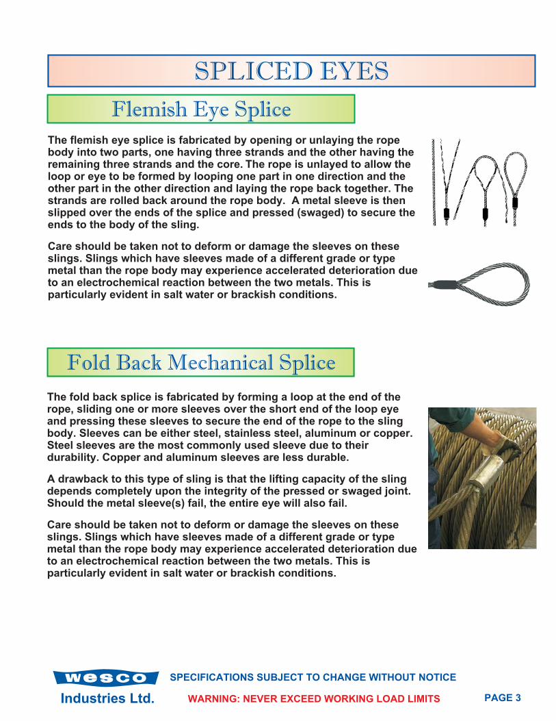
Flemish Eye Splice
Fold Back Mechanical Splice
The flemish eye splice is fabricated by opening or unlaying the ropebody into two parts, one having three strands and the other having theremaining three strands and the core. The rope is unlayed to allow theloop or eye to be formed by looping one part in one direction and theother part in the other direction and laying the rope back together. Thestrands are rolled back around the rope body. A metal sleeve is thenslipped over the ends of the splice and pressed (swaged) to secure theends to the body of the sling.
Care should be taken not to deform or damage the sleeves on theseslings. Slings which have sleeves made of a different grade or typemetal than the rope body may experience accelerated deterioration dueto an electrochemical reaction between the two metals. This isparticularly evident in salt water or brackish conditions.
The fold back splice is fabricated by forming a loop at the end of therope, sliding one or more sleeves over the short end of the loop eyeand pressing these sleeves to secure the end of the rope to the slingbody. Sleeves can be either steel, stainless steel, aluminum or copper.Steel sleeves are the most commonly used sleeve due to theirdurability. Copper and aluminum sleeves are less durable.
A drawback to this type of sling is that the lifting capacity of the slingdepends completely upon the integrity of the pressed or swaged joint.Should the metal sleeve(s) fail, the entire eye will also fail.
Care should be taken not to deform or damage the sleeves on theseslings. Slings which have sleeves made of a different grade or typemetal than the rope body may experience accelerated deterioration dueto an electrochemical reaction between the two metals. This isparticularly evident in salt water or brackish conditions.

Industries Ltd.
SPECIFICATIONS SUBJECT TO CHANGE WITHOUT NOTICE
PAGE 4WARNING: NEVER EXCEED WORKING LOAD LIMITS
Hand Tucked Splice
A hand tucked splice is made by passing the wire rope around athimble or forming an eye and splicing the dead end (short end) intothe live end (long end) of the rope. Normally, each dead end strand isgiven one forming tuck and three full tucks around the same strand inthe body of the rope. One additional full tuck is made when splicingmore pliable wire ropes such as 6 x 36 construction.
A Drawback to the type of splice is the reduction in sling working loadlimits. The use of a swivel on single leg lifts and free hanging loadswhich may rotate is not recommended. A tag line should always beused to prevent rotation of the sling body. When the sling body of ahand tucked splice is allowed to rotate, the splice will unlay, pull outand drop the load.
Becket Loop End
Becket loop ends are mechanically spliced onto the end of wire ropeto assist in the INSTALLATION PURPOSES ONLY. When installing newwire rope the loop assembly allows the connection of the new rope tothe existing rope without the use of wire mesh grips.
The becket fitting will be slightly larger than the diameter of wire rope.For further information on these fittings and sizes please contactWesco Industries.
Industries Ltd. PAGE 5WARNING: NEVER EXCEED WORKING LOAD LIMITS
SPECIFICATIONS SUBJECT TO CHANGE WITHOUT NOTICE
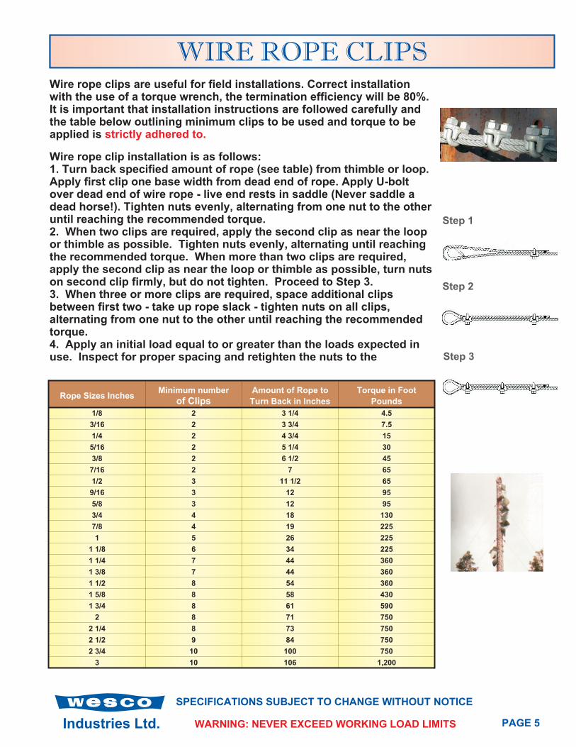
WIRE ROPE CLIPSWire rope clips are useful for field installations. Correct installationwith the use of a torque wrench, the termination efficiency will be 80%.It is important that installation instructions are followed carefully andthe table below outlining minimum clips to be used and torque to beapplied is strictly adhered to.
Wire rope clip installation is as follows:1. Turn back specified amount of rope (see table) from thimble or loop.Apply first clip one base width from dead end of rope. Apply U-boltover dead end of wire rope - live end rests in saddle (Never saddle adead horse!). Tighten nuts evenly, alternating from one nut to the otheruntil reaching the recommended torque.2. When two clips are required, apply the second clip as near the loopor thimble as possible. Tighten nuts evenly, alternating until reachingthe recommended torque. When more than two clips are required,apply the second clip as near the loop or thimble as possible, turn nutson second clip firmly, but do not tighten. Proceed to Step 3.3. When three or more clips are required, space additional clipsbetween first two - take up rope slack - tighten nuts on all clips,alternating from one nut to the other until reaching the recommendedtorque.4. Apply an initial load equal to or greater than the loads expected inuse. Inspect for proper spacing and retighten the nuts to the
Rope Sizes InchesMinimum number
of ClipsAmount of Rope to
Turn Back in Inches
Torque in Foot
Pounds
1/8 2 3 1/4 4.5
3/16 2 3 3/4 7.5
1/4 2 4 3/4 15
5/16 2 5 1/4 30
3/8 2 6 1/2 45
7/16 2 7 65
1/2 3 11 1/2 65
9/16 3 12 95
5/8 3 12 95
3/4 4 18 130
7/8 4 19 225
1 5 26 225
1 1/8 6 34 225
1 1/4 7 44 360
1 3/8 7 44 360
1 1/2 8 54 360
1 5/8 8 58 430
1 3/4 8 61 590
2 8 71 750
2 1/4 8 73 750
2 1/2 9 84 750
2 3/4 10 100 750
3 10 106 1,200
Step 1
Step 2
Step 3
Industries Ltd.
SPECIFICATIONS SUBJECT TO CHANGE WITHOUT NOTICE
PAGE 6WARNING: NEVER EXCEED WORKING LOAD LIMITS
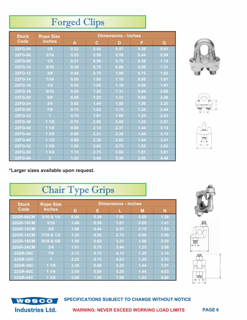
Forged Clips
StockCode
Rope SizeInches
Dimensions - Inches
A C D F G
22FG-04 1/8 0.22 0.44 0.47 0.38 0.81
22FG-06 3/16 0.25 0.56 0.59 0.44 0.94
22FG-08 1/4 0.31 0.50 0.75 0.56 1.19
22FG-10 5/16 0.38 0.75 0.88 0.69 1.31
22FG-12 3/8 0.44 0.75 1.00 0.75 1.63
22FG-14 7/16 0.50 1.00 1.19 0.88 1.81
22FG-16 1/2 0.50 1.00 1.19 0.88 1.91
22FG-18 9/16 0.56 1.25 1.31 0.94 2.06
22FG-20 5/8 0.56 1.25 1.31 0.94 2.06
22FG-24 3/4 0.62 1.44 1.50 1.06 2.25
22FG-28 7/8 0.75 1.62 1.75 1.25 2.44
22FG-32 1 0.75 1.81 1.88 1.25 2.63
22FG-36 1 1/8 0.75 2.00 2.00 1.25 2.81
22FG-40 1 1/4 0.88 2.13 2.31 1.44 3.13
22FG-44 1 3/8 0.88 2.31 2.38 1.44 3.13
22FG-48 1 1/2 0.88 2.38 2.62 1.44 3.41
22FG-52 1 5/8 1.00 2.62 2.75 1.63 3.63
22FG-56 1 3/4 1.13 2.75 3.06 1.81 3.81
22FG-64 2 1.25 3.00 3.38 2.00 4.44
Chair Type Grips
StockCode
Rope SizeInches
Dimensions - Inches
D E L M N
22GR-06CM 3/16 & 1/4 0.94 0.38 1.56 0.69 1.28
22GR-10CM 5/16 1.06 0.38 1.81 0.69 1.41
22GR-12CM 3/8 1.06 0.44 2.31 0.75 1.85
22GR-14CM 7/16 & 1/2 1.25 0.50 2.75 0.88 2.06
22GR-18CM 9/16 & 5/8 1.50 0.63 3.31 1.06 2.59
22GR-24CM 3/4 1.81 0.75 3.44 1.25 3.06
22GR-28C 7/8 2.13 0.75 4.13 1.25 3.14
22GR-32C 1 2.25 0.75 4.63 1.25 3.53
22GR-36C 1 1/8 2.38 0.88 5.25 1.44 3.91
22GR-40C 1 1/4 2.50 0.88 5.25 1.44 4.03
22GR-44C 1 3/8 3.00 1.00 7.00 1.63 4.66
*Larger sizes available upon request.
Industries Ltd. PAGE 7WARNING: NEVER EXCEED WORKING LOAD LIMITS
SPECIFICATIONS SUBJECT TO CHANGE WITHOUT NOTICE
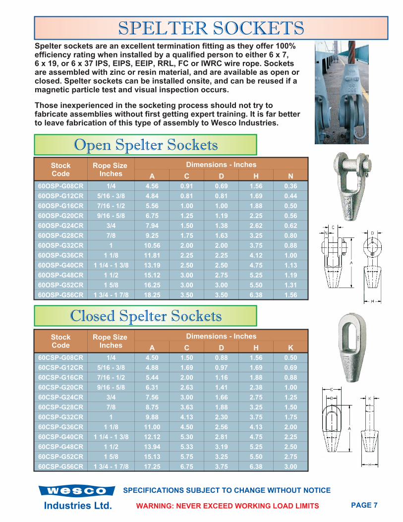
SPELTER SOCKETSSpelter sockets are an excellent termination fitting as they offer 100%efficiency rating when installed by a qualified person to either 6 x 7,6 x 19, or 6 x 37 IPS, EIPS, EEIP, RRL, FC or IWRC wire rope. Socketsare assembled with zinc or resin material, and are available as open orclosed. Spelter sockets can be installed onsite, and can be reused if amagnetic particle test and visual inspection occurs.
Those inexperienced in the socketing process should not try tofabricate assemblies without first getting expert training. It is far betterto leave fabrication of this type of assembly to Wesco Industries.
Open Spelter SocketsStockCode
Rope SizeInches
Dimensions - Inches
A C D H N
60OSP-G08CR 1/4 4.56 0.91 0.69 1.56 0.36
60OSP-G12CR 5/16 - 3/8 4.84 0.81 0.81 1.69 0.44
60OSP-G16CR 7/16 - 1/2 5.56 1.00 1.00 1.88 0.50
60OSP-G20CR 9/16 - 5/8 6.75 1.25 1.19 2.25 0.56
60OSP-G24CR 3/4 7.94 1.50 1.38 2.62 0.62
60OSP-G28CR 7/8 9.25 1.75 1.63 3.25 0.80
60OSP-G32CR 1 10.56 2.00 2.00 3.75 0.88
60OSP-G36CR 1 1/8 11.81 2.25 2.25 4.12 1.00
60OSP-G40CR 1 1/4 - 1 3/8 13.19 2.50 2.50 4.75 1.13
60OSP-G48CR 1 1/2 15.12 3.00 2.75 5.25 1.19
60OSP-G52CR 1 5/8 16.25 3.00 3.00 5.50 1.31
60OSP-G56CR 1 3/4 - 1 7/8 18.25 3.50 3.50 6.38 1.56
Closed Spelter SocketsStockCode
Rope SizeInches
Dimensions - Inches
A C D H K
60CSP-G08CR 1/4 4.50 1.50 0.88 1.56 0.50
60CSP-G12CR 5/16 - 3/8 4.88 1.69 0.97 1.69 0.69
60CSP-G16CR 7/16 - 1/2 5.44 2.00 1.16 1.88 0.88
60CSP-G20CR 9/16 - 5/8 6.31 2.63 1.41 2.38 1.00
60CSP-G24CR 3/4 7.56 3.00 1.66 2.75 1.25
60CSP-G28CR 7/8 8.75 3.63 1.88 3.25 1.50
60CSP-G32CR 1 9.88 4.13 2.30 3.75 1.75
60CSP-G36CR 1 1/8 11.00 4.50 2.56 4.13 2.00
60CSP-G40CR 1 1/4 - 1 3/8 12.12 5.30 2.81 4.75 2.25
60CSP-G48CR 1 1/2 13.94 5.33 3.19 5.25 2.50
60CSP-G52CR 1 5/8 15.13 5.75 3.25 5.50 2.75
60CSP-G56CR 1 3/4 - 1 7/8 17.25 6.75 3.75 6.38 3.00

Industries Ltd.
SPECIFICATIONS SUBJECT TO CHANGE WITHOUT NOTICE
PAGE 8WARNING: NEVER EXCEED WORKING LOAD LIMITS
SWAGE SOCKETSSwage sockets are suitable for either 6 x 19, or 6 x 37 IPS, EIPS, EEIP,RRL, and IWRC wire rope. Swage sockets have an efficiency rating of100%. Sockets are forged from special bar quality carbon steel and areswaged (pressed) onto the wire rope using special dies in a largehydraulic press.
Swage sockets are commonly used for pendant ropes on cranes.
Open Swage Sockets
StockCode
Rope SizeInches
Dimensions - Inches
A C D H M
60OSW-S08C 1/4 4.81 1.38 0.69 0.69 0.38
60OSW-S10C 5/16 6.25 1.62 0.81 0.81 0.47
60OSW-S12C 3/8 6.25 1.62 0.81 0.81 0.47
60OSW-S14C 7/16 7.81 2.00 1.00 1.00 0.56
60OSW-S16C 1/2 7.81 2.00 1.00 1.00 0.56
60OSW-S18C 9/16 9.50 2.38 1.19 1.25 0.68
60OSW-S20C 5/8 9.50 2.38 1.19 1.25 0.68
60OSW-S24C 3/4 11.56 2.75 1.38 1.50 0.78
60OSW-S28C 7/8 13.41 3.13 1.62 1.75 0.94
60OSW-S32C 1 15.47 3.69 2.00 2.00 1.06
60OSW-S36C 1 1/8 17.31 4.06 2.25 2.25 1.19
60OSW-S40C 1 1/4 19.06 4.50 2.53 2.50 1.22
Closed Swage Sockets
StockCode
Rope SizeInches
Dimensions - Inches
A B C D H
60CSW-S08C 1/4 4.31 0.50 1.38 0.75 0.50
60CSW-S10C 5/16 5.44 0.77 1.62 0.88 0.67
60CSW-S12C 3/8 5.44 0.77 1.62 0.88 0.67
60CSW-S14C 7/16 6.91 0.98 2.00 1.06 0.86
60CSW-S16C 1/2 6.91 0.98 2.00 1.06 0.86
60CSW-S18C 9/16 8.66 1.25 2.38 1.25 1.13
60CSW-S20C 5/8 8.66 1.25 2.38 1.25 1.13
60CSW-S24C 3/4 10.28 1.55 2.88 1.44 1.31
60CSW-S28C 7/8 11.94 1.70 3.12 1.69 1.50
60CSW-S32C 1 13.56 1.98 3.63 2.06 1.75
60CSW-S36C 1 1/8 15.03 2.25 4.00 2.31 2.00
60CSW-S40C 1 1/4 16.94 2.53 4.50 2.56 2.25
• Larger sizes available upon request.
Industries Ltd. PAGE 9WARNING: NEVER EXCEED WORKING LOAD LIMITS
SPECIFICATIONS SUBJECT TO CHANGE WITHOUT NOTICE
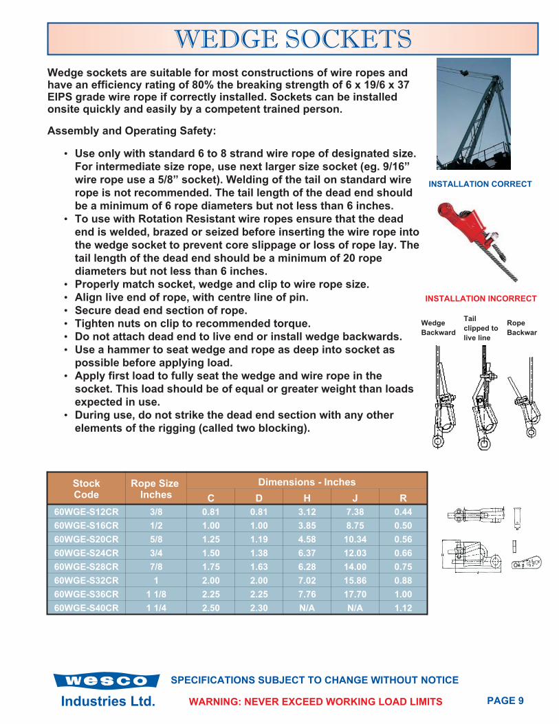
WEDGE SOCKETSWedge sockets are suitable for most constructions of wire ropes andhave an efficiency rating of 80% the breaking strength of 6 x 19/6 x 37EIPS grade wire rope if correctly installed. Sockets can be installedonsite quickly and easily by a competent trained person.
Assembly and Operating Safety:
• Use only with standard 6 to 8 strand wire rope of designated size.
For intermediate size rope, use next larger size socket (eg. 9/16”
wire rope use a 5/8” socket). Welding of the tail on standard wire
rope is not recommended. The tail length of the dead end should
be a minimum of 6 rope diameters but not less than 6 inches.
• To use with Rotation Resistant wire ropes ensure that the dead
end is welded, brazed or seized before inserting the wire rope into
the wedge socket to prevent core slippage or loss of rope lay. The
tail length of the dead end should be a minimum of 20 rope
diameters but not less than 6 inches.
• Properly match socket, wedge and clip to wire rope size.
• Align live end of rope, with centre line of pin.
• Secure dead end section of rope.
• Tighten nuts on clip to recommended torque.
• Do not attach dead end to live end or install wedge backwards.
• Use a hammer to seat wedge and rope as deep into socket as
possible before applying load.
• Apply first load to fully seat the wedge and wire rope in the
socket. This load should be of equal or greater weight than loads
expected in use.
• During use, do not strike the dead end section with any other
elements of the rigging (called two blocking).
StockCode
Rope SizeInches
Dimensions - Inches
C D H J R
60WGE-S12CR 3/8 0.81 0.81 3.12 7.38 0.44
60WGE-S16CR 1/2 1.00 1.00 3.85 8.75 0.50
60WGE-S20CR 5/8 1.25 1.19 4.58 10.34 0.56
60WGE-S24CR 3/4 1.50 1.38 6.37 12.03 0.66
60WGE-S28CR 7/8 1.75 1.63 6.28 14.00 0.75
60WGE-S32CR 1 2.00 2.00 7.02 15.86 0.88
60WGE-S36CR 1 1/8 2.25 2.25 7.76 17.70 1.00
60WGE-S40CR 1 1/4 2.50 2.30 N/A N/A 1.12
Wedge
Backward
Tail
clipped to
live line
Rope
Backwar
INSTALLATION CORRECT
INSTALLATION INCORRECT

Industries Ltd.
SPECIFICATIONS SUBJECT TO CHANGE WITHOUT NOTICE
PAGE 10WARNING: NEVER EXCEED WORKING LOAD LIMITS
STEEL STOPS (FERRULES)Steel stops are commonly used on 6 x 19 or 6 x 37 wire rope and isswaged onto the end of wire ropes to form an anchor point on winchdrums, anchor into steel fittings or to be used in conjunction withlogging fittings in the field. Ferrules are not intended for use inapplications where loads are fully suspended overhead.
Common sizes are as per the tables below, any other dimensions arecustom manufactured to your specifications.
Steel Ferrule
StockCode
Rope SizeInches
After Swage Dimensions (In.) Weight EachPoundsDiameter Length
30KNB-06 3/16 0.53 0.81 0.1
30KNB-08 1/4 0.53 1.12 0.2
30KNB-10 5/16 0.76 1.19 0.2
30KNB-12 3/8 0.76 1.56 0.3
30KNB-14 7/16 0.88 1.75 0.3
30KNB-16 1/2 1.01 1.75 0.3
30KNB-18 9/16 1.13 1.81 0.4
30KNB-20 5/8 1.53 2.00 0.9
30KNB-24 3/4 1.53 2.00 0.9
30KNB-DL28 7/8 2.04 2.25 2.0
30KNB-DL32 1 2.04 2.25 2.2
30KNB-DL36 1 1/8 2.26 2.37 2.2
30KNB-40 1 1/4 2.26 2.37 2.2
Choker Knob
StockCode
Rope SizeInches
Dimensions - Inches Weight EachPoundsDiameter Length
30CHK-12 3/8 1.08 1.69 0.3
30CHK-14 7/16 1.08 1.69 0.3
30CHK-16 1/2 1.08 1.69 0.3
30CHK-18 9/16 1.08 1.69 0.3
30CHK-20 5/8 1.45 2.25 0.8
30CHK-24 3/4 1.61 2.50 2.4
30CHK-28 7/8 2.04 3.00 2.3
30CHK-32 1 2.04 3.00 2.3
30CHK-36 1 1/8 2.26 3.00 2.6
• Please confirm dimensions of above if application is critical.

Industries Ltd. PAGE 11WARNING: NEVER EXCEED WORKING LOAD LIMITS
SPECIFICATIONS SUBJECT TO CHANGE WITHOUT NOTICE
Spiral Ferrule
StockCode
Rope SizeInches
DescriptionDimensions - Inches
Diameter Length
30SP-18/20M-S 7/16, 1/2, 9/16 M4 Silver 1.12 1.31
30SP-14/18 7/16, 1/2, 9/16 LB4 Cream 1.50 1.63
30SP-18/20M 9/16, 5/8 LB5 Pink 1.50 1.63
30SP-16 1/2 B4 Brown 2.00 1.69
30SP-36IM 5/8 B5 Maroon 2.00 1.69
30SP-24I 3/4 B6 Grey 2.00 1.69
30SP-24M 3/4 L6 White 2.12 2.31
30SP-28M 7/8 L7 Black 2.12 2.31
30SP-28RDI 7/8 J7 Red 2.44 2.63
30SP-32 1 L8 Green 2.12 2.31
30SP-32L8I 1 J8 Blue 1.44 2.63
30SP-36I 1 1/8 J9 Yellow 2.44 2.63
30SP-32M 1 1/4 J10 Orange 2.44 2.63
30SP-40I 1 1/4 S10 Purple 2.81 2.12
30SP-44I 1 3/8 S11 Gold 2.81 3.12
Spiral Ferrules with Manganese Bronze two piece wedges are easy toinstall and quick to change. The two piece wedge grips all the cable.Ferrules and wedges are reusable many times. Spiral ferrules arecommonly used in the forestry industry. Installation procedures are:
• Step 1 - Insert cable through ferrule in regular manner.
• Step 2 - Spread strands and lay them in individual wedge grooves.
• Step 3 - Tap wedge and cable down into ferrule to 3/8” from top.
• Step 4 - On the first load, both cable and wedge will seat solidly in
ferrule pocket.
Zinc Choker Ferrule
StockCode
Rope SizeInches
DescriptionDimensions - Inches
Diameter Length
30ZN-L331I 1/2, 5/8, 3/4 Bantam 2.00 1.69
30ZN-L332I 3/4, 7/8, 1 Light 2.12 2.63
30ZN-L334I 7/8, 1, 1 1/8 Junior 2.44 2.63
30ZN-L335I 1 1/4 1 3/8, 1 1/2 Standard 2.81 3.12
Standard zinc choker ferrules are reusable many times, because theheat treated, special alloy steel from which they are manufacturedeasily withstands the remelting of the zinc without damage. Ferrules arenot subject to mushrooming under normal conditions.

Industries Ltd.
SPECIFICATIONS SUBJECT TO CHANGE WITHOUT NOTICE
PAGE 12WARNING: NEVER EXCEED WORKING LOAD LIMITS
THIMBLESThimbles come in a varying range of shapes and sizes. They aredesigned to protect the wire rope from wear and damage when usingshackles and hooks. Thimbles can be supplied in either Galvanized,Stainless Steel, Bronze and Steel. The most common available is thestandard heavy duty thimble (see dimensions below). For other typesand sizes please contact Wesco for further details.
Stock CodeRope
DiameterInches
Dimensions - Inches
A B C D E Pin Dia.
76HD-G08 1/4 2.19 1.50 1.63 0.88 0.41 0.82
76HD-G10 5/16 2.50 1.82 1.88 1.06 0.50 0.94
76HD-G12 3/8 2.88 2.13 1.88 1.13 0.66 1.06
76HD-G14 7/16 3.25 2.38 2.38 1.25 0.75 1.18
76HD-G16 1/2 3.63 2.75 2.75 1.50 0.84 1.44
76HD-G18 9/16 3.63 2.75 2.75 1.50 0.90 1.44
76HD-G20 5/8 4.25 3.13 3.25 1.75 1.00 1.63
76HD-G24 3/4 5.00 3.75 3.75 2.00 1.25 1.88
76HD-G28 7/8 5.50 4.25 4.25 2.25 1.38 2.13
76HD-G32 1 6.13 5.00 4.50 2.50 1.56 2.38
76HD-G40 11/8-11/4 7.00 5.88 5.13 2.88 1.88 2.75
Heavy Duty Thimbles
EqualizingCombination
HalfSlip ThruSolid
HawserTowing
Heavy Duty Standard
Tube
Industries Ltd. PAGE 13WARNING: NEVER EXCEED WORKING LOAD LIMITS
SPECIFICATIONS SUBJECT TO CHANGE WITHOUT NOTICE
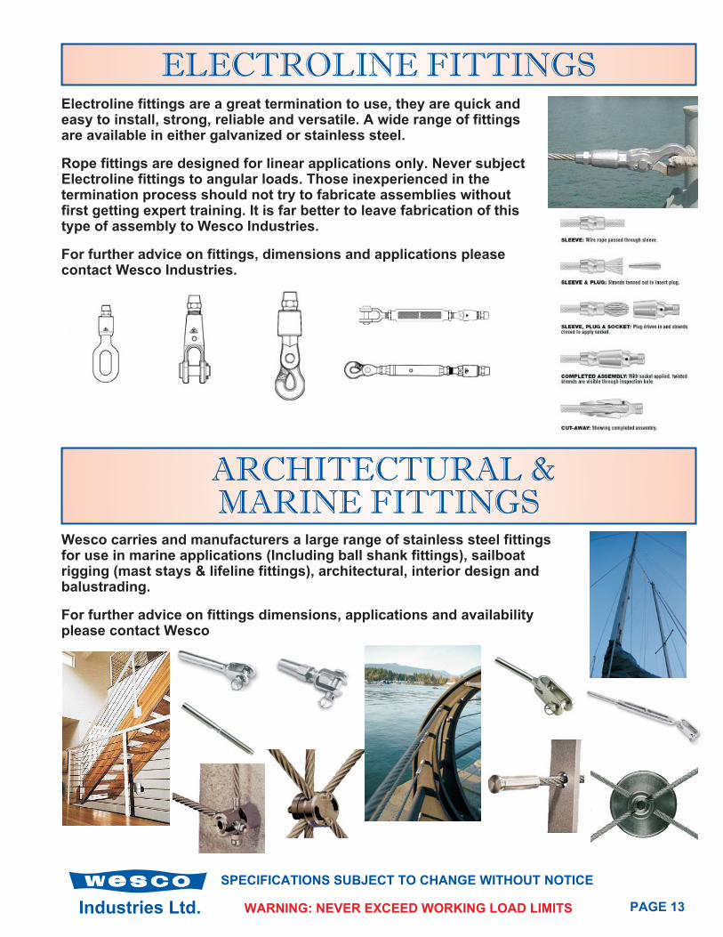
ELECTROLINE FITTINGSElectroline fittings are a great termination to use, they are quick andeasy to install, strong, reliable and versatile. A wide range of fittingsare available in either galvanized or stainless steel.
Rope fittings are designed for linear applications only. Never subjectElectroline fittings to angular loads. Those inexperienced in thetermination process should not try to fabricate assemblies withoutfirst getting expert training. It is far better to leave fabrication of thistype of assembly to Wesco Industries.
For further advice on fittings, dimensions and applications pleasecontact Wesco Industries.
ARCHITECTURAL &MARINE FITTINGS
Wesco carries and manufacturers a large range of stainless steel fittingsfor use in marine applications (Including ball shank fittings), sailboatrigging (mast stays & lifeline fittings), architectural, interior design andbalustrading.
For further advice on fittings dimensions, applications and availabilityplease contact Wesco
Industries Ltd.
SPECIFICATIONS SUBJECT TO CHANGE WITHOUT NOTICE
PAGE 14WARNING: NEVER EXCEED WORKING LOAD LIMITS
GRIPS
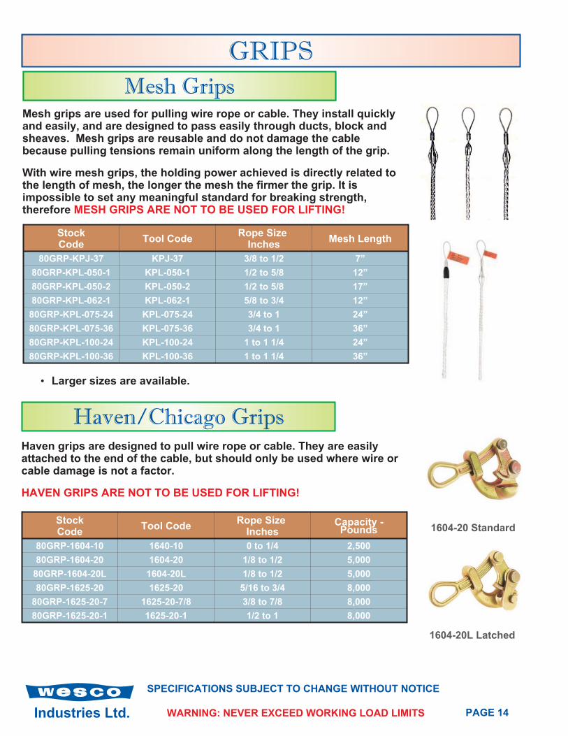
Mesh GripsMesh grips are used for pulling wire rope or cable. They install quicklyand easily, and are designed to pass easily through ducts, block andsheaves. Mesh grips are reusable and do not damage the cablebecause pulling tensions remain uniform along the length of the grip.
With wire mesh grips, the holding power achieved is directly related tothe length of mesh, the longer the mesh the firmer the grip. It isimpossible to set any meaningful standard for breaking strength,therefore MESH GRIPS ARE NOT TO BE USED FOR LIFTING!
StockCode
Tool CodeRope Size
InchesMesh Length
80GRP-KPJ-37 KPJ-37 3/8 to 1/2 7”
80GRP-KPL-050-1 KPL-050-1 1/2 to 5/8 12”
80GRP-KPL-050-2 KPL-050-2 1/2 to 5/8 17”
80GRP-KPL-062-1 KPL-062-1 5/8 to 3/4 12”
80GRP-KPL-075-24 KPL-075-24 3/4 to 1 24”
80GRP-KPL-075-36 KPL-075-36 3/4 to 1 36”
80GRP-KPL-100-24 KPL-100-24 1 to 1 1/4 24”
80GRP-KPL-100-36 KPL-100-36 1 to 1 1/4 36”
Haven/Chicago Grips
StockCode
Tool CodeRope Size
InchesCapacity -Pounds
80GRP-1604-10 1640-10 0 to 1/4 2,500
80GRP-1604-20 1604-20 1/8 to 1/2 5,000
80GRP-1604-20L 1604-20L 1/8 to 1/2 5,000
80GRP-1625-20 1625-20 5/16 to 3/4 8,000
80GRP-1625-20-7 1625-20-7/8 3/8 to 7/8 8,000
80GRP-1625-20-1 1625-20-1 1/2 to 1 8,000
Haven grips are designed to pull wire rope or cable. They are easilyattached to the end of the cable, but should only be used where wire orcable damage is not a factor.
HAVEN GRIPS ARE NOT TO BE USED FOR LIFTING!
• Larger sizes are available.
1604-20L Latched
1604-20 Standard
Industries Ltd. PAGE 15WARNING: NEVER EXCEED WORKING LOAD LIMITS
SPECIFICATIONS SUBJECT TO CHANGE WITHOUT NOTICE
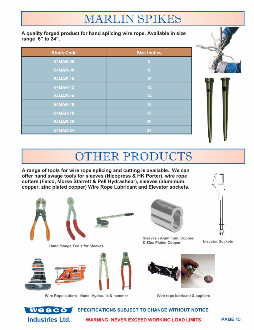
MARLIN SPIKESA quality forged product for hand splicing wire rope. Available in sizerange 6” to 24”.
Stock Code Size Inches
64MAR-06 6
64MAR-08 8
64MAR-10 10
64MAR-12 12
64MAR-14 14
64MAR-16 16
64MAR-18 18
64MAR-20 20
64MAR-24 24
OTHER PRODUCTSA range of tools for wire rope splicing and cutting is available. We canoffer hand swage tools for sleeves (Nicopress & HK Porter), wire ropecutters (Felco, Morse Starrett & Pell Hydrashear), sleeves (aluminum,copper, zinc plated copper) Wire Rope Lubricant and Elevator sockets.
Hand Swage Tools for Sleeves
Wire Rope cutters - Hand, Hydraulic & hammer Wire rope lubricant & appliers
Sleeves - Aluminum, Copper& Zinc Plated Copper Elevator Sockets

Rigging Centre: 2437 Beta AvenueBurnaby BC V5C 5N1
Phone: 604 292 1220Fax: 604 292 1222Email: [email protected]
Distributors of:
Wire Rope & Fittings - Powerstrand, Casar, Esco, Crosby.
Wire Rope all types of constructions and diameters, WireRope Fittings, Wire Rope Assemblies, Grips, Hooks, & Links.
Slings - Powerstrand, Gunnebo, Campbell, Procraft.
Wire Rope, Chain, Webbing, Endless Polyester & Rope.
Chain & Fittings - Campbell, Gunnebo - Grabiq, Procraft.
Grade 30, Mooring & Lashing, Grade 70, 80 & 100.
Hoists & Trolleys - Columbus Mckinnon, Coffing & Campbell.
Chain Hoists, Lever Hoists, Cummalongs, Electric Hoists, AirHoists, Winches, Beam Clamps & Trolleys.
Lifting Equipment- CM, Merrill, Terrier, Johnson, Rud, Crosby.
Shackles, Hooks, Plate Clamps, Crane Blocks, Eyebolts,Turnbuckles.
Cordage - Novatec Braid, Samson, Procraft.
Double Braid, 12 Strand, 8 Strand, 3 Strand & Cords.
Towing & Tie Down - Procraft, CM, Crosby.
Loadbinders, Straps, Chain & Hooks, & Wire RopeAssemblies.
Industries Supplied:
Crane, Construction, Logging, Marine, Industrial, Towing,Entertainment, Elevator, Mining, Offshore Oil & Gas, Fishing,Forestry, Utilities, Steel Works & Rigging.
© Copyright Wesco Industries Ltd 2004 January 2004
INDUSTRIES LTD.www.wescovan.com
Head Office: Unit 1, 9663-199A StreetLangley BC V1M 2X7
Phone: 604 881 3000Fax: 604 881 3010Email: [email protected]