model dt-311j and dt-311j-230v(ac) digital stroboscope
TRANSCRIPT

Model DT-311J
And
DT-311J-230V(AC)
DIGITAL STROBOSCOPE
INSTRUCTION MANUAL

1. GENERALThe DT-311J DIGITAL STROBOSCOPE is designed to assist mechanicaltiming adjustments and emit flashes synchronously with an externalsignal and an internal signal. Flashes can be delayed continuously from 0up to 359 degrees at a positive edge of an external signal by regulatingthe adjustment knob and the delayed angle is shown on the LED display.Zero position can be set to any optimal synchronous position. Revolutionsper minute (RPM) can also be displayed.
IMPORTANT SAFETY INSTRUCTIONSDo not apply a strong shock or rapid temperature change to the unit.Especially, do not leave it where temperature will rise: for instance, in aclosed automobile, exposed to direct sunlight, near a stove, open flame, etc.This instrument is protected against water drips. Do not spray or immerse inwater. Do not open and disassemble the unit. Make sure of proper voltage!
(1) Do not use stroboscope in an explosive atmosphere as it generates high electrical energy pulses.(2) To avoid potential eye damage, do not look directly at flashes.(3) Before operation, make sure there is no damage on the provided AC voltage line cable. If the cable is damaged, replace it with a new one.(4) To protect against water drips, carefully thread the power cable connector firmly to the stroboscope. After metal connector of the cable has been properly fitted onto the body, the power cable can then be safely plugged into a properly grounded AC receptacle.

2. SPECIFICATIONS (1) Flashing range 200 – 1,500 rpm
(2) Phase shift 0 – 359º(3) Internal signal range 200 up to 1,500 rpm(4) Delay setter ROTARY ENCODER(5) Display 4 digits, 10mm high, Red LED(6) Divided ratio 1/1, 1/2, 1/3, 1/4, 2/4 with shift(7) Input signal High level, 5 to 24v pulse width,
2 msec min. Low level, 0 to 1v pulse width, 2 msec min. 1p/r. Output impedance less than 10k ohms
(8) Input impedance 47k ohms(9) Display mode phase shift (degree), Tachometer(10) Accuracy +/- 1 digit(11) Flash tube Xenon lamp: Max 10W at 1,500 rpm
Life: 100 million flashes(12) Operating temperature 32º - 104º F (0 - 40º C)(13) Power requirement 110 VAC, (230VAC model) +/-10% at
50/60 Hz(14) Power consumption 20 VA MAX(15) Dimensions 8.43”L x 5.87”W x 6.85”H
(214 mm x 149 mm x 174 mm)(16) Weight 4.19 lb (1.9kg)(17) Accessories included 6m (19’) cable with connector, 1 pc.
Instruction manual, warranty card

3. DIAGRAMA. Front panel
(1) Xenon lamp(2) Protective window(3) Protective window screws(4) Reflector (5) Handle
B. Rear (Display & Operation panel)
(1) Delayed angle or rpm display(2) Mode indicators

(3) Power switch(4) Connector(5) Mode select switch(6) Setting knob: for Flash Rate and Phase Shift adjustment(7) Zero setting switch(8) Divide ratio select switch(9) Stroboscope flash: on/off switch
(10) Shift switch
4. CABLE CONNECTION Connect power and signal with provided cable as follows:
AC plug (with 3-prong plug) 110 VAC or 230VAC at 50/60 HzRed clip Signal (positive)Black clip 0V
5. MODE SELECTIONPress (MODE) switch (5) to select internal or external signal mode.

6. INTERNAL SIGNAL OPERATIONWhen internal signal mode is selected (‘INT’ LED on), flash rate isadjusted by turning the setting knob (6).
7. EXTERNAL SIGNAL OPERATIONWhen external signal mode is selected (‘deg’ or ‘rpm’ LED on), flashingrate is synchronized with the external signal.
Deg Delayed angle Degree rpm # of revolutions per 1 minute rpm
(1) DIVIDE RATIO SETTING (See 8. FLASH INTERVAL for detail)Select 1/1 to provide a flash per every 1 rotation.Select 1/2 to provide a flash per every 2 rotations.Select 1/3 to provide a flash per every 3 rotations.Select 1/4 to provide a flash per every 4 rotations.Select 2/4 to provide two continuously flashes per 4 rotations.
(2) PHASE SHIFTTurning the Phase shift setting knob clockwise or counterclockwise,;the flashing phase will be shifted.Pressing the zero set button (ZERO) makes the display “0” at anyangle.

8. FLASH INTERVAL
(1) FLASH MODE
Flashing behavior at each mode.
360°
Inputpulse
1 2 3 4 5 6 7 8 9 10
MODE 1/1 1 2 3 4 5 6 7 8 9 10
MODE 1/2 1 3 5 7 9
MODE 1/3 1 4 7 10
MODE 1/4 1 5 9
MODE 2/4 1 2 5 6 9 10

Every time you depress the shift button (SHIFT), the flashes slide to the next pulse.
1 2 3 4 5 6 7 8 9 10Inputpulse
MODE 1/2 1 3 5 7 9
ON 2 4 6 8 10
MODE 1/3 1 4 7 10
ON 2 5 8
ON 3 6 9
ON 1 4 7 10
MODE 1/4 1 5 9
ON 2 6 10
ON 3 7
ON 4 8
ON 1 5 9

MODE 2/4 1 2 5 6 9 10
ON 2 3 6 7 10
ON 3 4 7 8
ON 1 4 5 8 9
ON 1 2 5 6 9 10
9. LAMP ON/OFF SWITCHLAMP ON/OFF switch provides power to the lamp. To save the flash tubeand general lamp life, turn the lamp off when not in operation.
Once power is applied and no adjustments are made during the next 30minutes, the flashing will automatically turn off the lamp causing thedisplay to flash rapidly. To continue operation, press the LAMP ON/OFFswitch and the flashing will continue. for another 30 minutes.

10. ALARMS
1. LOW SPEED INDICATOR (External signal operation only)Below 180 rpm, the “under” symbol appears.
At degree mode
At rpm mode
2. HIGH SPEED INDICATOR (External signal operation only)
Over 1,550rpm “over” symbol appears.
At degree mode
At rpm mode
If AC power is low, the flashing will stop and “LLLL” will be displayed.If an alarm symbol appears, (“under”, “over”) the stroboscope flash willnot function.

11. INPUT CIRCUITRY
12. LAMP REPLACEMENT
Indications:• Lamp life is about 100 million flashes.• Rotation speed is displayed, no flash is emitted.• When the flash is intermittently emitted, this indicates the lamp must
be replaced.• Only replace flash tube with the specified lamp: (FLASHTUBE311-J).
Directions:(1) After unplugging the line cable from the power line, let the
stroboscope sit for about 30 minutes or longer. Be sure stroboscope iscool to the touch before replacing the lamp.
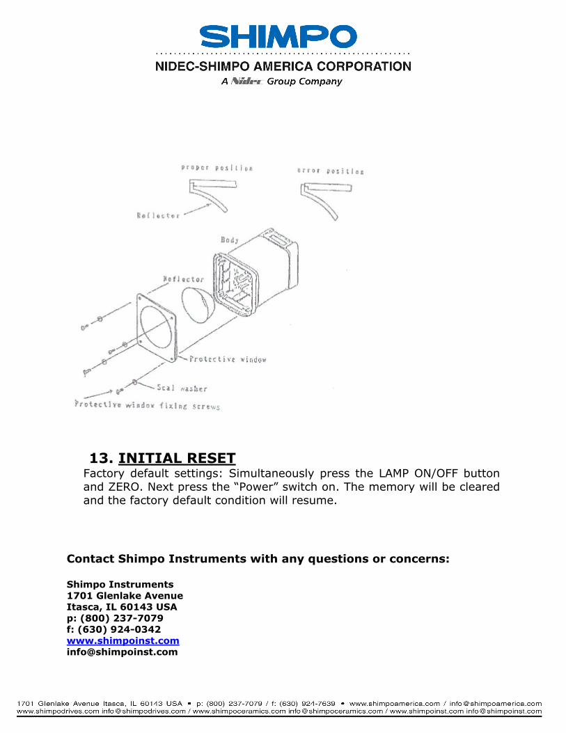
(2) Remove the lamp protection window by loosening the 4 screws on thewindow. Insert a fine screw driver into a hole of the protection windowand pull out.
(3) Remove the reflector and pull out the lamp base. Caution, do not pullout the lamp glass directly.
(4) Do not touch the flash tube with fingers. Use a clean cloth. Press thelamp base to the socket in the proper direction to install the newlamp.
(5) Important: In order to maintain protection against water, be sure tomount the reflector in the center. Fix the reflector on the formerposition and fix the protective window with the 4 screws and thesealing washers.
13. INITIAL RESETFactory default settings: Simultaneously press the LAMP ON/OFF buttonand ZERO. Next press the “Power” switch on. The memory will be clearedand the factory default condition will resume.
Contact Shimpo Instruments with any questions or concerns:
Shimpo Instruments1701 Glenlake AvenueItasca, IL 60143 USAp: (800) 237-7079f: (630) [email protected]