testo 477 led hand stroboscope - manoraz.com · led hand stroboscope instruction manual . ... basic...
TRANSCRIPT
testo 477
LED hand stroboscope
Instruction manual

1 Contents
3
Pos: 1 /TD/Überschriften/1. Inhalt @ 0\mod_1177587817070_79.doc @ 1243 @ 1
1 Contents 1 Contents ................................................................................................... 3
2 Safety and the environment .................................................................... 4 2.1. About this document ........................................................................ 4 2.2. Ensure safety ................................................................................... 5 2.3. Protecting the environment .............................................................. 6
3 Specifications .......................................................................................... 7 3.1. Use .................................................................................................. 7 3.2. Scope of delivery ............................................................................. 7 3.3. Technical data ................................................................................. 8
4 Product description ............................................................................... 10 4.1. Overview........................................................................................ 10 4.2. Status displays .............................................................................. 11
5 First steps .............................................................................................. 11 5.1. Commissioning .............................................................................. 11
5.1.1. Inserting batteries/rechargeable batteries ...................................................... 11 5.1.2. Switching the instrument on ........................................................................... 12 5.1.3. Connecting the trigger cable .......................................................................... 12
6 Using the product .................................................................................. 13 6.1. Performing settings ........................................................................ 13
6.1.1. Setting options ............................................................................................... 14 6.1.2. Factory reset .................................................................................................. 15 6.1.3. Key lock ......................................................................................................... 15 6.1.4. Internal/external trigger signal ........................................................................ 15
7 Application information ........................................................................ 16 7.1. General application information ..................................................... 16
7.1.1. Slowing down motion ..................................................................................... 16 7.1.2. Apparent direction of movement .................................................................... 16 7.1.3. Harmonics ..................................................................................................... 17 7.1.4. Determing an object’s true RPM .................................................................... 17
7.2. Instructions for use for the special functions of the instrument ...... 20
8 Maintaining the product ........................................................................ 21 8.1. Changing batteries/rechargeable batteries .................................... 21
Pos: 2 /TD/--- Seitenwechsel --- @ 0\mod_1173774430601_0.doc @ 283 @
2 Safety and the environment
4
Pos: 3 /TD/Überschriften/2. Sicherheit und Umwelt @ 0\mod_1173774719351_79.doc @ 292 @ 1
2 Safety and the environment Pos: 4 /TD/Überschriften/2.1 Zu diesem Dokument @ 0\mod_1173775252351_79.doc @ 346 @ 2
2.1. About this document Pos: 5 /TD/Sicherheit und Umwelt/Zu diesem Dokument/Verwendung (Standard) @ 0\mod_1173775068554_79.doc @ 337 @ 5
Use
> Please read this documentation through carefully and familiarize yourself with the product before putting it to use. Pay particular attention to the safety instructions and warning advice in order to prevent injuries and damage to the products.
> Keep this document to hand so that you can refer to it when necessary.
> Hand this documentation on to any subsequent users of the product.
Pos: 6 /TD/Sicherheit und Umwelt/Zu diesem Dokument/Symbole und Schreibkonv. [Standard] @ 0\mod_1174982140622_79.doc @ 515 @ 5
Symbols and writing standards
Representation Explanation
Warning advice, risk level according to the signal word:
Warning! Serious physical injury may occur.
Caution! Slight physical injury or damage to the equipment may occur.
> Implement the specified precautionary measures.
Note: Basic or further information.
1. ... 2. ...
Action: more steps, the sequence must be followed.
> ... Action: a step or an optional step.
- ... Result of an action.
Menu Elements of the instrument, the instrument display or the program interface.
[OK] Control keys of the instrument or buttons of the program interface.
... | ... Functions/paths within a menu.
“...” Example entries
2 Safety and the environment
5
Pos: 7 /TD/Überschriften/2.2 Sicherheit gewährleisten @ 0\mod_1173780783960_79.doc @ 366 @ 2
2.2. Ensure safety Pos: 8 /TD/Sicherheit und Umwelt/Sicherheit gewährleisten/Produkt bestimmungsgemäß verwenden @ 0\mod_1173781261848_79.doc @ 386 @
> Only operate the product properly, for its intended purpose and within the parameters specified in the technical data. Do not use any force.
Pos: 9 /TD/Sicherheit und Umwelt/Sicherheit gewährleisten/testo 477/Epileptischer Anfall @ 4\mod_1249047250843_79.doc @ 46948 @
WARNING Danger of injury!
> Use of stroboscopes may trigger epileptic seizures in people susceptible to these.
Pos: 10 /TD/Sicherheit und Umwelt/Sicherheit gewährleisten/testo 477/Beobachtete Maschine @ 4\mod_1249047460506_79.doc @ 46979 @
WARNINGDanger of injury!
> Do not touch observed machines/objects. Pos: 11 /TD/Sicherheit und Umwelt/Sicherheit gewährleisten/testo 477/Augenverletzung @ 4\mod_1251376140864_79.doc @ 47593 @
WARNING Danger of injury!
> Do not look into the LED beam and never point the beam at people or animals.
> Never point the LED beam at mirrors or other reflective surfaces. The beam, deflected uncontrollably, could hit people or animals.
Pos: 12 /TD/Sicherheit und Umwelt/Sicherheit gewährleisten/testo 477/Stromschlag @ 4\mod_1249047102854_79.doc @ 46917 @
CAUTIONLoss of the warranty claim!
> Do not open instrument. There are no parts in the instrument that can be maintained by the user.
Pos: 13 /TD/Sicherheit und Umwelt/Sicherheit gewährleisten/testo 477/Batterien @ 4\mod_1253086170962_79.doc @ 50403 @
CAUTIONDamage to equipment!
> If the instrument is not used for a longer period, remove all batteries/rechargeable batteries from the instrument.

2 Safety and the environment
6
Pos: 14 /TD/Überschriften/2.3 Umwelt schützen @ 0\mod_1173780843645_79.doc @ 375 @ 2
2.3. Protecting the environment Pos: 15.1 /TD/Sicherheit und Umwelt/Umwelt schützen/Akkus/Batterien entsorgen @ 0\mod_1175693637007_79.doc @ 619 @
> Dispose of faulty rechargeable batteries/spent batteries in accordance with the valid legal specifications.
Pos: 15.2 /TD/Sicherheit und Umwelt/Umwelt schützen/Produkt entsorgen @ 0\mod_1173780307072_79.doc @ 357 @
> At the end of its useful life, send the product to the separate collection for electric and electronic devices (observe local regulations) or return the product to Testo for disposal.
Pos: 16 /TD/--- Seitenwechsel --- @ 0\mod_1173774430601_0.doc @ 283 @
3 Specifications
7
Pos: 17 /TD/Überschriften/3. Leistungsbeschreibung @ 0\mod_1173774791554_79.doc @ 301 @ 1
3 Specifications Pos: 18 /TD/Leistungsbeschreibung/Verwendung/testo 477 @ 4\mod_1249031406678_79.doc @ 46665 @ 2
3.1. Use The testo 477 can be used in many areas of industry, research & development, in laboratories and universities.
Normally, the testo 477 is used when the aim is to show fast-moving objects in slow motion. In this case, you can analyze their movement securely and smoothly, check for proper procedures and determine undesirable sources of vibrations etc.
You can also use the testo 477 to seemingly "freeze" the movement of an object. Without making contact with the object, you can precisely determine its rotational speed or the frequency of shifts in direction.
Compared to other portable stroboscopes, the testo 477 LED stroboscope can be operated with just one hand.
Customary uses/applications:
• High-speed assembly lines, feed systems, filling systems etc.
• Presses and looms
• Motors, fans, pumps and turbines
• Calibration and test instruments
• Monitoring laboratory and research facilities Pos: 19 /TD/Leistungsbeschreibung/Lieferumfang/Lieferumfang 477 @ 4\mod_1249033000565_79.doc @ 46696 @ 2
3.2. Scope of delivery The testo 477 is delivered with the following accessories:
• testo 477 LED stroboscope
• Cable with connector for external trigger signals
• Case
• Instruction manual
• Calibration report
• 6 batteries (AA) Pos: 20 /TD/Leistungsbeschreibung/Technische Daten/Technische Daten 477 @ 4\mod_1249041732539_79.doc @ 46854 @ 2
3 Specifications
8
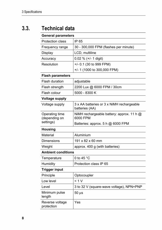
3.3. Technical data
General parameters
Protection class IP 65
Frequency range 30 - 300,000 FPM (flashes per minute)
Display LCD, multiline
Accuracy 0.02 % (+/- 1 digit)
Resolution +/- 0.1 (30 to 999 FPM)
+/- 1 (1000 to 300,000 FPM)
Flash parameters
Flash duration adjustable
Flash strength 2200 Lux @ 6000 FPM / 30cm
Flash colour 5000 - 8300 K
Voltage supply
Voltage supply 3 x AA batteries or 3 x NiMH rechargeable batteries (AA)
Operating time (depending on settings)
NiMH rechargeable battery: approx. 11 h @ 6000 FPM
Batteries: approx. 5 h @ 6000 FPM
Housing
Material Aluminium
Dimensions 191 x 82 x 60 mm
Weight approx. 400 g (with batteries)
Ambient conditions
Temperature 0 to 45 °C
Humidity Protection class IP 65
Trigger input
Principle Optocoupler
Low level < 1 V
Level 3 to 32 V (square-wave voltage), NPN+PNP
Minimum pulse length
50 μs
Reverse voltage protection
Yes
3 Specifications
9
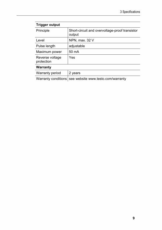
Trigger output
Principle Short-circuit and overvoltage-proof transistor output
Level NPN, max. 32 V
Pulse length adjustable
Maximum power 50 mA
Reverse voltage protection
Yes
Warranty
Warranty period 2 years
Warranty conditions see website www.testo.com/warranty # Pos: 21 /TD/Überschriften/4. Produktbeschreibung @ 0\mod_1173774846679_79.doc @ 310 @ 1
4 Product description
10
4 Product description Pos: 22 /TD/Produktbeschreibung/Übersicht/Übersicht 477 @ 4\mod_1249033237734_79.doc @ 46727 @ 2
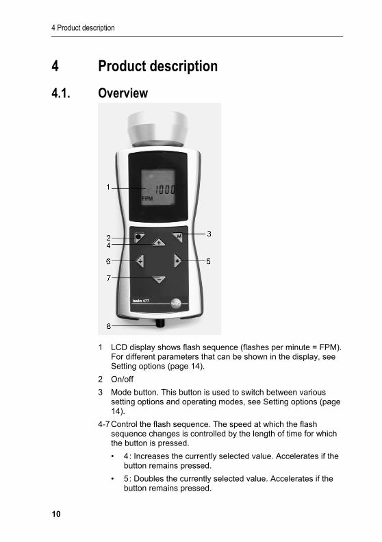
4.1. Overview
1 LCD display shows flash sequence (flashes per minute = FPM). For different parameters that can be shown in the display, see Setting options (page 14).
2 On/off
3 Mode button. This button is used to switch between various setting options and operating modes, see Setting options (page 14).
4-7 Control the flash sequence. The speed at which the flash sequence changes is controlled by the length of time for which the button is pressed.
• 4 : Increases the currently selected value. Accelerates if the button remains pressed.
• 5 : Doubles the currently selected value. Accelerates if the button remains pressed.
5 First steps
11
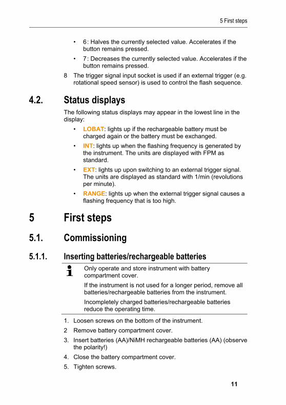
• 6 : Halves the currently selected value. Accelerates if the button remains pressed.
• 7 : Decreases the currently selected value. Accelerates if the button remains pressed.
8 The trigger signal input socket is used if an external trigger (e.g. rotational speed sensor) is used to control the flash sequence.
Pos: 23 /TD/Produktbeschreibung/Statusanzeigen 477 @ 4\mod_1249563194258_79.doc @ 47253 @ 2
4.2. Status displays
The following status displays may appear in the lowest line in the display:
• LOBAT: lights up if the rechargeable battery must be charged again or the battery must be exchanged.
• INT: lights up when the flashing frequency is generated by the instrument. The units are displayed with FPM as standard.
• EXT: lights up upon switching to an external trigger signal. The units are displayed as standard with 1/min (revolutions per minute).
• RANGE: lights up when the external trigger signal causes a flashing frequency that is too high.
Pos: 24 /TD/Überschriften/5. Erste Schritte @ 0\mod_1173774895039_79.doc @ 319 @ 1
5 First steps Pos: 25 /TD/Überschriften/5.1 Inbetriebnahme @ 0\mod_1185342823812_79.doc @ 1885 @ 2
5.1. Commissioning Pos: 26 /TD/Erste Schritte/testo 477/Batterien einlegen @ 4\mod_1249037621082_79.doc @ 46759 @ 3
5.1.1. Inserting batteries/rechargeable batteries
Only operate and store instrument with battery compartment cover.
If the instrument is not used for a longer period, remove all batteries/rechargeable batteries from the instrument.
Incompletely charged batteries/rechargeable batteries reduce the operating time.
1. Loosen screws on the bottom of the instrument.
2 Remove battery compartment cover.
3. Insert batteries (AA)/NiMH rechargeable batteries (AA) (observe the polarity!)
4. Close the battery compartment cover.
5. Tighten screws.
5 First steps
12
Pos: 27 /TD/Erste Schritte/testo 477/Gerät einschalten @ 4\mod_1249038795222_79.doc @ 46823 @ 3
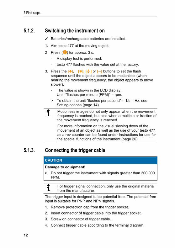
5.1.2. Switching the instrument on ✓ Batteries/rechargeable batteries are installed.
1. Aim testo 477 at the moving object.
2 Press ( ) for approx. 3 s.
- A display test is performed.
- testo 477 flashes with the value set at the factory.
3. Press the [], �[], [ ] or [–] buttons to set the flash sequence until the object appears to be motionless (when nearing the movement frequency, the object appears to move slower).
- The value is shown in the LCD display. Unit: "flashes per minute (FPM)" = rpm.
> To obtain the unit "flashes per second" = 1/s = Hz: see Setting options (page 14).
Motionless images do not only appear when the movement frequency is reached, but also when a multiple or fraction of the movement frequency is reached.
For more information on the visual slowing down of the movement of an object as well as the use of your testo 477 as a rev counter can be found under Instructions for use for the special functions of the instrument (page 20).
Pos: 28 /TD/Produkt verwenden/testo 477/Triggerkabel anschließen @ 4\mod_1249463514430_79.doc @ 47214 @ 3
5.1.3. Connecting the trigger cable
CAUTION
Damage to equipment!
> Do not trigger the instrument with signals greater than 300,000 FPM.
For trigger signal connection, only use the original material from the manufacturer.
The trigger input is designed to be potential-free. The potential-free input is suitable for PNP and NPN signals.
1. Remove protection cap from the trigger socket.
2. Insert connector of trigger cable into the trigger socket.
3. Screw on connector of trigger cable.
4. Connect trigger cable according to the terminal diagram.
6 Using the product
13
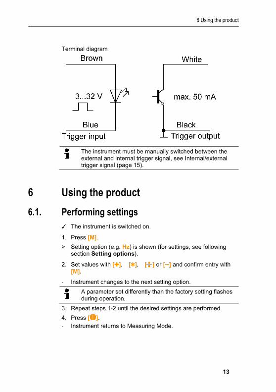
Terminal diagram
The instrument must be manually switched between the external and internal trigger signal, see Internal/external trigger signal (page 15).
Pos: 29 /TD/Überschriften/6. Produkt verwenden @ 0\mod_1173774928554_79.doc @ 328 @ 1
6 Using the product Pos: 30 /TD/Überschriften/6.1 Einstellungen vornehmen @ 0\mod_1184584321421_79.doc @ 1863 @ 2
6.1. Performing settings Pos: 31 /TD/Produkt verwenden/testo 477/Einstellungen vornehmen @ 4\mod_1249460650835_79.doc @ 47183 @ 3333
✓ The instrument is switched on.
1. Press [M].
> Setting option (e.g. Hz) is shown (for settings, see following section Setting options).
2. Set values with [], �[],� [ ] or [–] and confirm entry with [M].
- Instrument changes to the next setting option.
A parameter set differently than the factory setting flashes during operation.
3. Repeat steps 1-2 until the desired settings are performed.
4. Press [ ]. - Instrument returns to Measuring Mode.
6 Using the product
14
6.1.1. Setting options
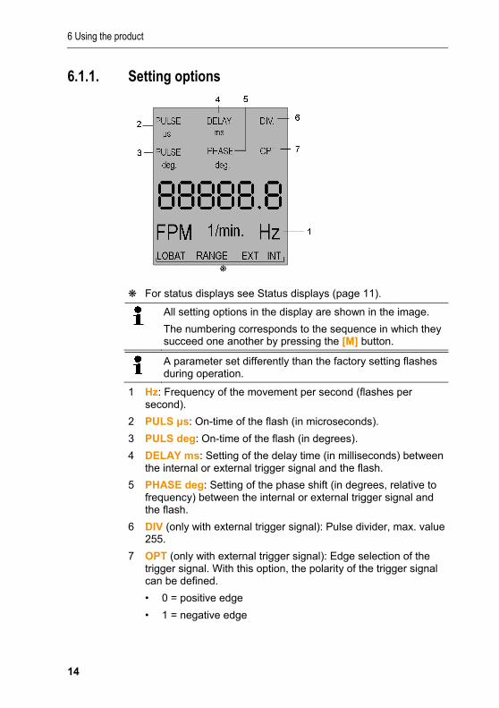
For status displays see Status displays (page 11).
All setting options in the display are shown in the image.
The numbering corresponds to the sequence in which they succeed one another by pressing the [M] button.
A parameter set differently than the factory setting flashes during operation.
1 Hz: Frequency of the movement per second (flashes per second).
2 PULS μs: On-time of the flash (in microseconds).
3 PULS deg: On-time of the flash (in degrees).
4 DELAY ms: Setting of the delay time (in milliseconds) between the internal or external trigger signal and the flash.
5 PHASE deg: Setting of the phase shift (in degrees, relative to frequency) between the internal or external trigger signal and the flash.
6 DIV (only with external trigger signal): Pulse divider, max. value 255.
7 OPT (only with external trigger signal): Edge selection of the trigger signal. With this option, the polarity of the trigger signal can be defined.
• 0 = positive edge
• 1 = negative edge
6 Using the product
15
6.1.2. Factory reset ✓ The instrument is switched on.
1. Press [M] + [–].
- Instrument is reset to the factory settings.
- Instrument returns to Measuring Mode.
6.1.3. Key lock ✓ The instrument is switched on.
1. Press [ ] + [–].
- Key lock is activated.
2. Press [ ] + [–].
- Key lock is deactivated.
6.1.4. Internal/external trigger signal
The instrument is set to an internal trigger signal at the factory.
✓ The instrument is switched on.
✓ When switching to an external trigger signal: Trigger cable is
connected, see Connecting the trigger cable (page 12).
1. Press [M] + [ ].
- The instrument switches from internal trigger signal to external trigger signal.
- The status display EXT appears in the display and the unit changes to 1/min.
2. Press [M] + [ ].
- The instrument switches from external trigger signal to internal trigger signal.
- The status display INT appears in the display and the unit changes to FPM.
7 Application information
16
Pos: 32 /TD/Überschriften/Anwendungshinweise 477 @ 4\mod_1251901467301_79.doc @ 48178 @ 1
7 Application information Pos: 33 /TD/Produkt verwenden/testo 477/allgemeine Anwendungshinweise 477 @ 4\mod_1251878000012_79.doc @ 48147 @ 23333
7.1. General application information
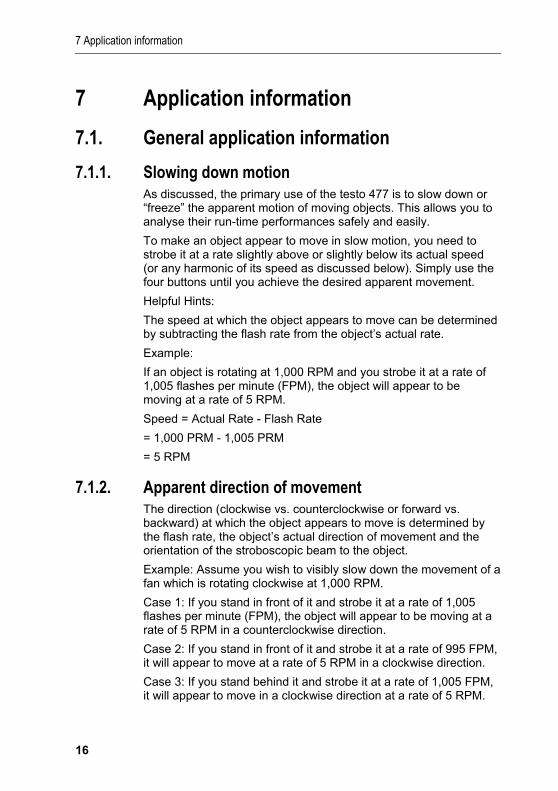
7.1.1. Slowing down motion As discussed, the primary use of the testo 477 is to slow down or “freeze” the apparent motion of moving objects. This allows you to analyse their run-time performances safely and easily.
To make an object appear to move in slow motion, you need to strobe it at a rate slightly above or slightly below its actual speed (or any harmonic of its speed as discussed below). Simply use the four buttons until you achieve the desired apparent movement.
Helpful Hints:
The speed at which the object appears to move can be determined by subtracting the flash rate from the object’s actual rate.
Example:
If an object is rotating at 1,000 RPM and you strobe it at a rate of 1,005 flashes per minute (FPM), the object will appear to be moving at a rate of 5 RPM.
Speed = Actual Rate - Flash Rate
= 1,000 PRM - 1,005 PRM
= 5 RPM
7.1.2. Apparent direction of movement The direction (clockwise vs. counterclockwise or forward vs. backward) at which the object appears to move is determined by the flash rate, the object’s actual direction of movement and the orientation of the stroboscopic beam to the object.
Example: Assume you wish to visibly slow down the movement of a fan which is rotating clockwise at 1,000 RPM.
Case 1: If you stand in front of it and strobe it at a rate of 1,005 flashes per minute (FPM), the object will appear to be moving at a rate of 5 RPM in a counterclockwise direction.
Case 2: If you stand in front of it and strobe it at a rate of 995 FPM, it will appear to move at a rate of 5 RPM in a clockwise direction.
Case 3: If you stand behind it and strobe it at a rate of 1,005 FPM, it will appear to move in a clockwise direction at a rate of 5 RPM.
7 Application information
17
Case 4: If you stand behind it and strobe it at a rate of 995 FPM, it will appear to move in a counterclockwise direction at a rate of 5 RPM.
7.1.3. Harmonics If you continuously increase the flash rate while strobing an object, it may appear to freeze, slow down, speed up, go forward, freeze again, go backwards, form multiple images, etc. These images appear at mathematically determined multiples or harmonics of the object’s actual speed.
Example: Assume you wish to slow the motion of the fan used in the last example, but you want it to be brighter.
Technique: Starting from 1,000 FPM, slowly increase the flash rate. At 1,500 FPM the image will appear to freeze again. Continue to increase the rate.
The image will appear to freeze again at 3,000 FPM. At this rate, the fan appears to be very bright.You can now use the four buttons to vary the rate above and below 3,000 to make the fan appear to move both clockwise and counterclockwise.
Helpful Hints:
• Harmonic images appear at both whole number multiples as well as fractional intervals of the object’s actual rate. For example, a fan rotating at 1,000 RPM will appear to be frozen at the whole number multiples of 2,000 (2x), 3,000 (3x), 4,000 (4x) etc., as well as at the fractional rates of 500 (1/2x), 750 (3/4x) and 1,500 (1 1/2x), etc.
• Some of the harmonic images are “singular” in appearance while others are “multiple”. This becomes important if you want to determine the objects actual rate as discussed in chapter Determing an object’s true RPM.
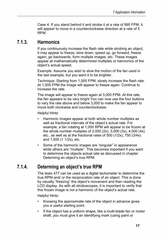
7.1.4. Determing an object’s true RPM The testo 477 can be used as a digital tachometer to determine the true RPM and/ or the reciprocation rate of an object. This is done by visually “freezing” the object’s movement and then reading the LCD display. As with all stroboscopes, it is important to verify that this frozen image is not a harmonic of the object’s actual rate.
Helpful Hints:
• Knowing the approximate rate of the object in advance gives you a useful starting point.
• If the object has a uniform shape, like a multi-blade fan or motor shaft, you must give it an identifying mark (using paint or
7 Application information
18
reflective tape or equivalent) in order to differentiate its orientation.
• A single image always appears if the rotational speed set on the instrument matches the rotational speed of the object or if an integer divisor (1/2, 1/3, ...) of the object speed has been set on the instrument.
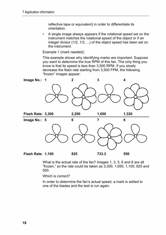
Example 1 (mark needed):
This example shows why identifying marks are important. Suppose you want to determine the true RPM of this fan. The only thing you know is that its speed is less than 3,500 RPM. If you slowly decrease the flash rate starting from 3,500 FPM, the following “frozen” images appear:
Image No.: 1 2 3 4
Flash Rate: 3,300 2,200 1,650 1,320
Image No.: 5 6 7 8
Flash Rate: 1,100 825 733.3 550
What is the actual rate of the fan? Images 1, 3, 5, 6 and 8 are all “frozen,” so the rate could be taken as 3,300, 1,650, 1,100, 825 and 550.
Which is correct?
In order to determine the fan’s actual speed, a mark is added to one of the blades and the test is run again.
7 Application information
19
Image No.:
1 2 3 4
Flash Rate:
3,300 2,200 1,650 1,320
Image No.:
5 6 7 8
Flash Rate:
1,100 825 733.3 550
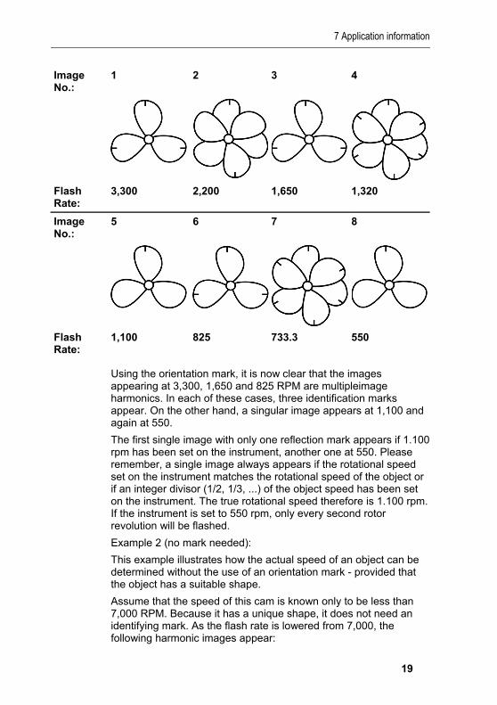
Using the orientation mark, it is now clear that the images appearing at 3,300, 1,650 and 825 RPM are multipleimage harmonics. In each of these cases, three identification marks appear. On the other hand, a singular image appears at 1,100 and again at 550.
The first single image with only one reflection mark appears if 1.100 rpm has been set on the instrument, another one at 550. Please remember, a single image always appears if the rotational speed set on the instrument matches the rotational speed of the object or if an integer divisor (1/2, 1/3, ...) of the object speed has been set on the instrument. The true rotational speed therefore is 1.100 rpm. If the instrument is set to 550 rpm, only every second rotor revolution will be flashed.
Example 2 (no mark needed):
This example illustrates how the actual speed of an object can be determined without the use of an orientation mark - provided that the object has a suitable shape.
Assume that the speed of this cam is known only to be less than 7,000 RPM. Because it has a unique shape, it does not need an identifying mark. As the flash rate is lowered from 7,000, the following harmonic images appear:
7 Application information
20
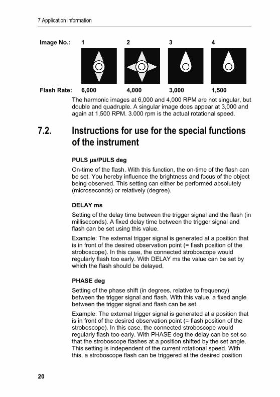
Image No.: 1 2 3 4
Flash Rate: 6,000 4,000 3,000 1,500
The harmonic images at 6,000 and 4,000 RPM are not singular, but double and quadruple. A singular image does appear at 3,000 and again at 1,500 RPM. 3.000 rpm is the actual rotational speed.
Pos: 34 /TD/Überschriften/x.x. Spezielle Anwendungshinweise 477 @ 4\mod_1249399750136_79.doc @ 47113 @ 2
7.2. Instructions for use for the special functions of the instrument
Pos: 35 /TD/Produkt verwenden/testo 477/Anwendungshinweis 477 @ 4\mod_1249399957795_79.doc @ 47145 @ 55555
PULS μs/PULS deg
On-time of the flash. With this function, the on-time of the flash can be set. You hereby influence the brightness and focus of the object being observed. This setting can either be performed absolutely (microseconds) or relatively (degree).
DELAY ms
Setting of the delay time between the trigger signal and the flash (in milliseconds). A fixed delay time between the trigger signal and flash can be set using this value.
Example: The external trigger signal is generated at a position that is in front of the desired observation point (= flash position of the stroboscope). In this case, the connected stroboscope would regularly flash too early. With DELAY ms the value can be set by which the flash should be delayed.
PHASE deg
Setting of the phase shift (in degrees, relative to frequency) between the trigger signal and flash. With this value, a fixed angle between the trigger signal and flash can be set.
Example: The external trigger signal is generated at a position that is in front of the desired observation point (= flash position of the stroboscope). In this case, the connected stroboscope would regularly flash too early. With PHASE deg the delay can be set so that the stroboscope flashes at a position shifted by the set angle. This setting is independent of the current rotational speed. With this, a stroboscope flash can be triggered at the desired position
8 Maintaining the product
21
even with fluctuating rotational speeds or when the system is starting up.
DIV (pulse divider)
This function is only active with an external trigger signal. A value x can be set with the pulse divider. The external trigger signal is then divided by this value.
Example: An external trigger (e.g. rotational speed sensor) that scans a gear wheel provides a signal with every tooth. With DIV value = 10, a flash is only triggered with every 10th signal.
OPT
Edge selection of the trigger signal. 0 = positive edge , 1 = negative edge. With this option, the polarity of the trigger signal can be defined.
Pos: 36 /TD/Überschriften/7. Produkt instand halten @ 0\mod_1173789831362_79.doc @ 397 @ 1
8 Maintaining the product Pos: 37 /TD/Produkt instand halten/testo 477/Batterien wechseln @ 4\mod_1249038428877_79.doc @ 46791 @ 2
8.1. Changing batteries/rechargeable batteries
Only operate and store instrument with battery compartment cover.
If the instrument is not used for a longer period, remove all batteries/rechargeable batteries from the instrument.
Incompletely charged batteries/rechargeable batteries reduce the operating time.
1. Loosen screws on the bottom of the instrument.
2 Remove battery compartment cover.
3. Remove batteries/rechargeable batteries.
4. Insert new batteries (AA)/charged NiMH rechargeable batteries (AA) (observe the polarity!)
5. Close the battery compartment cover.
6. Tighten screws. Pos: 38 /TD/Produkt instand halten/Gerät reinigen @ 0\mod_1180083446579_79.doc @ 1748 @ 5
Cleaning the instrument
> If the housing of the instrument is dirty, clean it with a damp cloth.
Do not use any aggressive cleaning agents or solvents! Weak household cleaning agents and soap suds may be used.

8 Maintaining the product
22
=== Ende der Liste für Textmarke Inhalt ===


0970 4770 en 03