milroyal c drive - milton roy · 2 installation, operations maintenance manual 1.1 introduction the...
TRANSCRIPT

MILROYAL® C DRIVEIOM ManualManual No : 53939Rev. : 00Rev. Date : 11/2015

iInstallation, Operations & Maintenance Manual
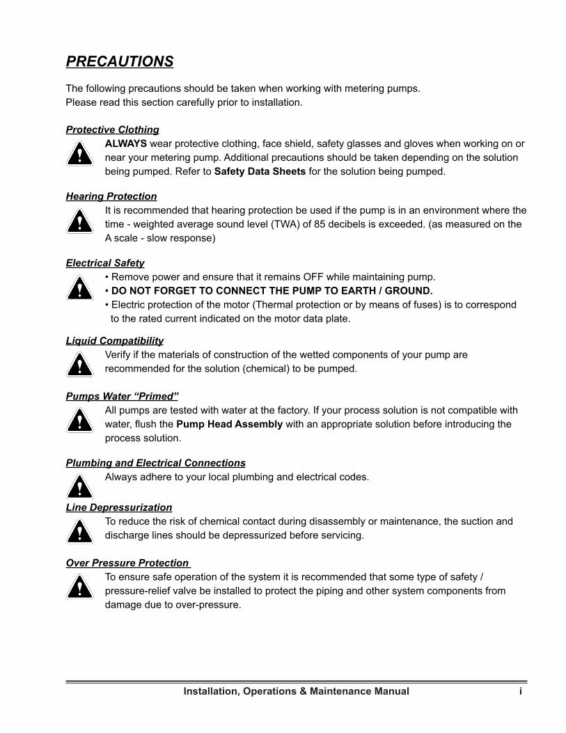
PRECAUTIONSThe following precautions should be taken when working with metering pumps. Please read this section carefully prior to installation.
Protective ClothingALWAYS wear protective clothing, face shield, safety glasses and gloves when working on or near your metering pump. Additional precautions should be taken depending on the solution being pumped. Refer to Safety Data Sheets for the solution being pumped.
Hearing ProtectionIt is recommended that hearing protection be used if the pump is in an environment where the time - weighted average sound level (TWA) of 85 decibels is exceeded. (as measured on the A scale - slow response)
Electrical Safety• Remove power and ensure that it remains OFF while maintaining pump.• DO NOT FORGET TO CONNECT THE PUMP TO EARTH / GROUND.• Electric protection of the motor (Thermal protection or by means of fuses) is to correspond to the rated current indicated on the motor data plate.
Liquid CompatibilityVerify if the materials of construction of the wetted components of your pump are recommended for the solution (chemical) to be pumped.
Pumps Water “Primed”All pumps are tested with water at the factory. If your process solution is not compatible with water, flush the Pump Head Assembly with an appropriate solution before introducing the process solution.
Plumbing and Electrical ConnectionsAlways adhere to your local plumbing and electrical codes.
Line DepressurizationTo reduce the risk of chemical contact during disassembly or maintenance, the suction and discharge lines should be depressurized before servicing.
Over Pressure Protection To ensure safe operation of the system it is recommended that some type of safety / pressure-relief valve be installed to protect the piping and other system components from damage due to over-pressure.

ii Installation, Operations & Maintenance Manual
LiftingThis manual should be used as a guide only - Follow your company’s recommended lifting procedures. It is not intended to replace or take precedence over recommendations, policies and procedures judged as safe due to the local environment than what is contained herein. Use lifting equipment that is rated for the weight of the equipment to be lifted.

iiiInstallation, Operations & Maintenance Manual
TABLE OF CONTENTS
SECTION 1 - GENERAL DESCRIPTION . . . . . . . . . . . . . . . . . . . . . . . . . . . . . . . . . . . . . . . . . . . . . . . . . . . . . . . 2
1.1 INTRODUCTION . . . . . . . . . . . . . . . . . . . . . . . . . . . . . . . . . . . . . . . . . . . . . . . . . . . . . . . . . . . . . . . . . 2
1.2 MODEL CODE / PUMP IDENTIFICATION. . . . . . . . . . . . . . . . . . . . . . . . . . . . . . . . . . . . . . . . . . . . . . 2
1.3 PRINCIPLE OF OPERATION . . . . . . . . . . . . . . . . . . . . . . . . . . . . . . . . . . . . . . . . . . . . . . . . . . . . . . . 2
1.4 SAFETY PRECAUTIONS. . . . . . . . . . . . . . . . . . . . . . . . . . . . . . . . . . . . . . . . . . . . . . . . . . . . . . . . . . . 4
1.5 SPECIFICATIONS . . . . . . . . . . . . . . . . . . . . . . . . . . . . . . . . . . . . . . . . . . . . . . . . . . . . . . . . . . . . . . . . 4
SECTION 2 - INSTALLATION . . . . . . . . . . . . . . . . . . . . . . . . . . . . . . . . . . . . . . . . . . . . . . . . . . . . . . . . . . . . . . . . 5
2.1 UNPACKING / INSPECTION. . . . . . . . . . . . . . . . . . . . . . . . . . . . . . . . . . . . . . . . . . . . . . . . . . . . . . . . 5
2.2 STORAGE . . . . . . . . . . . . . . . . . . . . . . . . . . . . . . . . . . . . . . . . . . . . . . . . . . . . . . . . . . . . . . . . . . . . . . 5
2.2.1 Short Term Storage (Less than 6 Months) . . . . . . . . . . . . . . . . . . . . . . . . . . . . . . . . . . . . . . . . . . . . 5
2.2.2 Long Term Storage(Longer than 6 Months) . . . . . . . . . . . . . . . . . . . . . . . . . . . . . . . . . . . . . . . . . . . 5
2.2.3 Pump Drive and Gearboxes . . . . . . . . . . . . . . . . . . . . . . . . . . . . . . . . . . . . . . . . . . . . . . . . . . . . . . . 5
2.2.4 Pump Liquid Ends. . . . . . . . . . . . . . . . . . . . . . . . . . . . . . . . . . . . . . . . . . . . . . . . . . . . . . . . . . . . . . . 5
2.2.5 Pneumatic, Electrical and Electronic Equipment . . . . . . . . . . . . . . . . . . . . . . . . . . . . . . . . . . . . . . . 6
2.3 SAFETY PRECAUTIONS . . . . . . . . . . . . . . . . . . . . . . . . . . . . . . . . . . . . . . . . . . . . . . . . . . . . . . . . . . 6
2.4 PUMP MOUNTING / LOCATION. . . . . . . . . . . . . . . . . . . . . . . . . . . . . . . . . . . . . . . . . . . . . . . . . . . . . 6
2.5 PIPING . . . . . . . . . . . . . . . . . . . . . . . . . . . . . . . . . . . . . . . . . . . . . . . . . . . . . . . . . . . . . . . . . . . . . . . 7
2.5.1 General. . . . . . . . . . . . . . . . . . . . . . . . . . . . . . . . . . . . . . . . . . . . . . . . . . . . . . . . . . . . . . . . . . . . . . . 7
2.5.2 Suction Piping. . . . . . . . . . . . . . . . . . . . . . . . . . . . . . . . . . . . . . . . . . . . . . . . . . . . . . . . . . . . . . . . . . 7
2.5.3 Discharge Piping . . . . . . . . . . . . . . . . . . . . . . . . . . . . . . . . . . . . . . . . . . . . . . . . . . . . . . . . . . . . . . . 8
2.6 VENTED RISERS . . . . . . . . . . . . . . . . . . . . . . . . . . . . . . . . . . . . . . . . . . . . . . . . . . . . . . . . . . . . . . . . 9
2.7 PULSATION DAMPENERS . . . . . . . . . . . . . . . . . . . . . . . . . . . . . . . . . . . . . . . . . . . . . . . . . . . . . . . . . 9
2.8 BACK PRESSURE VALVES . . . . . . . . . . . . . . . . . . . . . . . . . . . . . . . . . . . . . . . . . . . . . . . . . . . . . . . . 9
2.9 SAFETY VALVES. . . . . . . . . . . . . . . . . . . . . . . . . . . . . . . . . . . . . . . . . . . . . . . . . . . . . . . . . . . . . . . . 10
2.10 CHECK VALVES . . . . . . . . . . . . . . . . . . . . . . . . . . . . . . . . . . . . . . . . . . . . . . . . . . . . . . . . . . . . . . . 10
2.11 SHUT-OFF VALVES . . . . . . . . . . . . . . . . . . . . . . . . . . . . . . . . . . . . . . . . . . . . . . . . . . . . . . . . . . . . . 11
2.12 SERVICE CONNECTIONS . . . . . . . . . . . . . . . . . . . . . . . . . . . . . . . . . . . . . . . . . . . . . . . . . . . . . . . 11
2.12.1 Pump Drive . . . . . . . . . . . . . . . . . . . . . . . . . . . . . . . . . . . . . . . . . . . . . . . . . . . . . . . . . . . . . . . . . . 11
2.12.2 Stuffing Box. . . . . . . . . . . . . . . . . . . . . . . . . . . . . . . . . . . . . . . . . . . . . . . . . . . . . . . . . . . . . . . . . . 12
2.12.3 Drains . . . . . . . . . . . . . . . . . . . . . . . . . . . . . . . . . . . . . . . . . . . . . . . . . . . . . . . . . . . . . . . . . . . . . . 12
2.12.4 Auxiliary (Accessory) Equipment . . . . . . . . . . . . . . . . . . . . . . . . . . . . . . . . . . . . . . . . . . . . . . . . . 12
SECTION 3 - OPERATION . . . . . . . . . . . . . . . . . . . . . . . . . . . . . . . . . . . . . . . . . . . . . . . . . . . . . . . . . . . . . . . . . 13
3.1 INITIAL START-UP. . . . . . . . . . . . . . . . . . . . . . . . . . . . . . . . . . . . . . . . . . . . . . . . . . . . . . . . . . . . . . . 13
3.2 OIL SPECIFICATIONS . . . . . . . . . . . . . . . . . . . . . . . . . . . . . . . . . . . . . . . . . . . . . . . . . . . . . . . . . . . 13
3.3 INITIAL ADJUSTMENT . . . . . . . . . . . . . . . . . . . . . . . . . . . . . . . . . . . . . . . . . . . . . . . . . . . . . . . . . . . 13
3.3.1 Micrometer Capacity Control . . . . . . . . . . . . . . . . . . . . . . . . . . . . . . . . . . . . . . . . . . . . . . . . . . . . . 13
3.3.2 Electric Capacity Control . . . . . . . . . . . . . . . . . . . . . . . . . . . . . . . . . . . . . . . . . . . . . . . . . . . . . . . . 13
3.3.3 Pneumatic Capacity Calibration . . . . . . . . . . . . . . . . . . . . . . . . . . . . . . . . . . . . . . . . . . . . . . . . . . . 13
3.3.4 Speed Capacity Control . . . . . . . . . . . . . . . . . . . . . . . . . . . . . . . . . . . . . . . . . . . . . . . . . . . . . . . . . 13
3.3.5 Capacity Calibration . . . . . . . . . . . . . . . . . . . . . . . . . . . . . . . . . . . . . . . . . . . . . . . . . . . . . . . . . . . . 14

iv Installation, Operations & Maintenance Manual
3.4 FILLING PUMP SYSTEM . . . . . . . . . . . . . . . . . . . . . . . . . . . . . . . . . . . . . . . . . . . . . . . . . . . . . . . . . 14
3.5 PREVENTATIVE MAINTENANCE. . . . . . . . . . . . . . . . . . . . . . . . . . . . . . . . . . . . . . . . . . . . . . . . . . . 14
3.5.1 Drive . . . . . . . . . . . . . . . . . . . . . . . . . . . . . . . . . . . . . . . . . . . . . . . . . . . . . . . . . . . . . . . . . . . . . . 14
3.5.2 Motor . . . . . . . . . . . . . . . . . . . . . . . . . . . . . . . . . . . . . . . . . . . . . . . . . . . . . . . . . . . . . . . . . . . . . . 14
3.5.3 Check Valves . . . . . . . . . . . . . . . . . . . . . . . . . . . . . . . . . . . . . . . . . . . . . . . . . . . . . . . . . . . . . . . . 14
SECTION 4 - MAINTENANCE . . . . . . . . . . . . . . . . . . . . . . . . . . . . . . . . . . . . . . . . . . . . . . . . . . . . . . . . . . . . . . . 15
4.1 SPARE PARTS . . . . . . . . . . . . . . . . . . . . . . . . . . . . . . . . . . . . . . . . . . . . . . . . . . . . . . . . . . . . . . . . . 15
4.2 RETURNING UNITS TO THE FACTORY . . . . . . . . . . . . . . . . . . . . . . . . . . . . . . . . . . . . . . . . . . . . . 15
4.3 DISASSEMBLY . . . . . . . . . . . . . . . . . . . . . . . . . . . . . . . . . . . . . . . . . . . . . . . . . . . . . . . . . . . . . . . . . 15
4.3.1 Pump Drive . . . . . . . . . . . . . . . . . . . . . . . . . . . . . . . . . . . . . . . . . . . . . . . . . . . . . . . . . . . . . . . . . . . 15
4.3.2 Crosshead Removal . . . . . . . . . . . . . . . . . . . . . . . . . . . . . . . . . . . . . . . . . . . . . . . . . . . . . . . . . . . . 16
4.3.3 Gear Housing Removal . . . . . . . . . . . . . . . . . . . . . . . . . . . . . . . . . . . . . . . . . . . . . . . . . . . . . . . . . 16
4.4 REASSEMBLY. . . . . . . . . . . . . . . . . . . . . . . . . . . . . . . . . . . . . . . . . . . . . . . . . . . . . . . . . . . . . . . . . . 17
4.4.1 Pump Drive . . . . . . . . . . . . . . . . . . . . . . . . . . . . . . . . . . . . . . . . . . . . . . . . . . . . . . . . . . . . . . . . . . . 17
4.4.2 Crosshead . . . . . . . . . . . . . . . . . . . . . . . . . . . . . . . . . . . . . . . . . . . . . . . . . . . . . . . . . . . . . . . . . . . 18
SECTION 5 - TROUBLESHOOTING GUIDE . . . . . . . . . . . . . . . . . . . . . . . . . . . . . . . . . . . . . . . . . . . . . . . . . . . . 19
SECTION 6 - PARTS . . . . . . . . . . . . . . . . . . . . . . . . . . . . . . . . . . . . . . . . . . . . . . . . . . . . . . . . . . . . . . . . . . . . . . 24
6.1 GENERAL . . . . . . . . . . . . . . . . . . . . . . . . . . . . . . . . . . . . . . . . . . . . . . . . . . . . . . . . . . . . . . . . . . . . . 24
6.2 ILLUSTRATED PARTS LIST . . . . . . . . . . . . . . . . . . . . . . . . . . . . . . . . . . . . . . . . . . . . . . . . . . . . . . . 24
6.3 MILROYAL® C DRIVE. . . . . . . . . . . . . . . . . . . . . . . . . . . . . . . . . . . . . . . . . . . . . . . . . . . . . . . . . . . . . 27
LIST OF ILLUSTRATIONSFIGURE 1. Milroyal® C Metering Pump . . . . . . . . . . . . . . . . . . . . . . . . . . . . . . . . . . . . . . . . . . . . . . . . . . . . . . . . . . 1
FIGURE 2. Capacity Adjustment . . . . . . . . . . . . . . . . . . . . . . . . . . . . . . . . . . . . . . . . . . . . . . . . . . . . . . . . . . . . . . 2
FIGURE 3. Packed Plunger Liquid End (Shown with optional oiler) (See manual 54270) . . . . . . . . . . . . . . . . . . . 3
FIGURE 4. HPD Liquid End (See manual 54146) . . . . . . . . . . . . . . . . . . . . . . . . . . . . . . . . . . . . . . . . . . . . . . . . . 4
FIGURE 5. Float Box . . . . . . . . . . . . . . . . . . . . . . . . . . . . . . . . . . . . . . . . . . . . . . . . . . . . . . . . . . . . . . . . . . . . . . . 8
FIGURE 6. Vented Riser. . . . . . . . . . . . . . . . . . . . . . . . . . . . . . . . . . . . . . . . . . . . . . . . . . . . . . . . . . . . . . . . . . . . . 9
FIGURE 7. Safety and Back Pressure Valve . . . . . . . . . . . . . . . . . . . . . . . . . . . . . . . . . . . . . . . . . . . . . . . . . . . . . 10
FIGURE 8. Recommended Valve Locations . . . . . . . . . . . . . . . . . . . . . . . . . . . . . . . . . . . . . . . . . . . . . . . . . . . . . 11
FIGURE 9. Pump Nameplate . . . . . . . . . . . . . . . . . . . . . . . . . . . . . . . . . . . . . . . . . . . . . . . . . . . . . . . . . . . . . . . . 15
FIGURE 10. Pump Drive Parts . . . . . . . . . . . . . . . . . . . . . . . . . . . . . . . . . . . . . . . . . . . . . . . . . . . . . . . . . . . . . . . 22
FIGURE 11. Special Tools . . . . . . . . . . . . . . . . . . . . . . . . . . . . . . . . . . . . . . . . . . . . . . . . . . . . . . . . . . . . . . . . . . . 23
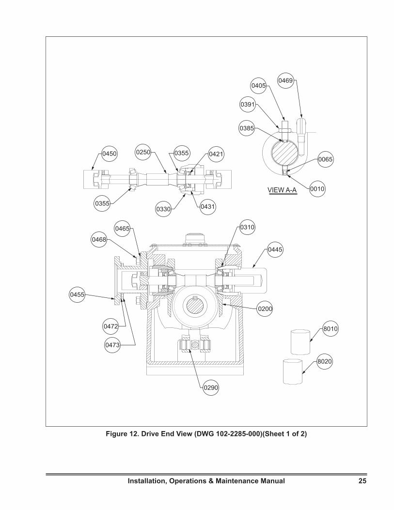
FIGURE 12. Drive End View Drawing (102-2285-000) (Sheet 1 of 2). . . . . . . . . . . . . . . . . . . . . . . . . . . . . . . . . . 25
FIGURE 12. Drive Side and Top Views Drawing (102-2285-000) (Sheet 2 of 2) . . . . . . . . . . . . . . . . . . . . . . . . . 26

1Installation, Operations & Maintenance Manual
Figure 1. Milroyal® C Metering Pump.

2 Installation, Operations & Maintenance Manual
1.1 INTRODUCTIONThe Milroyal® C is a reciprocating positive-displacement controlled-volume pump designed to move specific volumes of liquid against a positive pressure differential between the pump suction and the pump discharge. The delivered volume is controllable within one percent of setting.The pump consists of three major components: (1) a drive unit, (2) a reciprocating plunger, and (3) a liquid end. Pump delivery is a function of drive speed, plunger stroke length, and plunger diameter. In addition, delivered volume for a given pump can be varied by mechanical (micrometer hand knob) or (optional) electrical or pneumatic adjustment of plunger stroke length. Pump drives may be fitted with HPD (High Performance Diaphragm, Manual 54146) as well as several styles of PP (Packed Plunger, Manual 54270) liquid ends (See Figures 3 and 4). This manual will concentrate on the mechanically adjusted drive unit only.
1.2 MODEL CODE / PUMP IDENTIFICATIONMilroyal® C pumps manufactured during and after 1995 were given a new model code which completely defines the material and options selected. The first digits indicate the frame size, followed by the “options” code. See manual 54146 for HPD model number breakdown and 54270 for PP model number breakdown.
1.3 PRINCIPLE OF OPERATIONThe drive unit moves the pump plunger to draw liquid into the liquid end on the suction stroke and to expel the liquid on the subsequent discharge stroke. Accurate flow control is achievable only if the discharge line pressure (discharge head) is greater than the suction line pressure (suction head). For aid in determining acceptable piping performance, please refer to Milton Roy’s NPSH calculator, available on line at www.miltonroy.com.The unique Milroyal® C pump drive mechanism operates on a patented polar crank principle. Essentially, a crank driven by a worm gear rotates on a variable plane. As the crank plane is changed from vertical, a reciprocating motion results from the crank connection to the plunger. Pump stroke length is increased from zero to maximum by adjusting the slope of the crank plane from vertical. (See Figure 2.)
Figure 2. Capacity Adjustment
SECTION 1 - GENERAL DESCRIPTION

3Installation, Operations & Maintenance Manual
SECTION 1 - GENERAL DESCRIPTION
As the plunger reciprocates in the liquid end, the pumped liquid is alternately drawn into and discharged from the liquid end. Each suction (rearward) stroke of the pump plunger creates a negative pressure in the displacement chamber. The pressure of the liquid in the suction line unseats the suction ball-checks and liquid flows into the displacement chamber. On the discharge stroke, the plunger moves forward and pressurizes the liquid which unseats the discharge ball-checks to flow out the discharge port. On each suction stroke, the discharge ball-checks are seated, and on each discharge stroke, the suction ball-checks are seated (pressure in pump head is greater than suction line pressure). This mode of operation prevents back flow and ensures liquid movement from the suction port, through the liquid end, and out the discharge port.
In packed plunger liquid ends, the plunger contacts the process liquid, while diaphragm liquid ends isolate the process liquid from the pump plunger. In the latter designs, the plunger displaces hydraulic fluid which moves a diaphragm in contact with the process liquid, forcing the process liquid through the liquid end. Liquid ends are covered in separate instruction manuals.
Figure 3. Packed Plunger Liquid End (See manual 54270)

4 Installation, Operations & Maintenance Manual
1.4 SAFETY PRECAUTIONSWhen installing, operating, and maintaining the Milroyal® C keep safety considerations foremost. Use proper tools, protective clothing, and eye protection when working on the equipment. Install the equipment with a view toward ensuring safe operation. Follow the instructions in this manual and take additional safety measures appropriate to the l iquid being pumped. Be extremely careful in the presence of hazardous substances (e.g., corrosive, toxins, solvents, acids, caustics, flammables, etc.).
1.5 SPECIFICATIONSDetailed specifications for this pump are listed on the pump Data Sheet. The sheet can be downloaded at www.miltonroy.com.
Figure 4. HPD Liquid End (See manual 54146)
The following is a list of manuals that may be required to maintain your Milroyal® C pump:
Title Document NumberDisc Diaphragm Liquid End 54145
Milroyal® C Pneumatic Capacity Control 54269
Double Diaphragm Leak Detector 54148
Metallic Diaphragm Liquid End 54151
Electronic Capacity Control 53870
The manuals can be downloaded on the internet at www.miltonroy.com.
SECTION 1 - GENERAL DESCRIPTION
5Installation, Operations & Maintenance Manual
2.1 UNPACKING / INSPECTIONPumps are shipped Free on Board (FOB) factory or representative warehouse and the title passes to the customer when the carrier signs for receipt of the pump. In the event that damages occur during shipment, it is the responsibility of the customer to notify the carrier immediately and to file a damage claim.Carefully examine the shipping crate upon receipt from the carrier to be sure there is no obvious damage to the contents. Open the crate carefully so accessory items fastened to the inside of the crate will not be damaged or lost. Examine all material inside the crate and check against the packing list to be sure that all items are accounted for and intact.
2.2 STORAGE
2.2.1 Short Term Storage (Less than 6 Months)It is preferable to store the material under a shelter in its original package to protect it from adverse weather conditions. In condensing atmospheres, follow the long term storage procedure.
2.2.2 Long Term Storage (Longer than 6 Months)The primary consideration in storage of pump equipment is to prevent corrosion of external and internal components. This corrosion is caused by natural circulation of air as temperature of the surroundings change from day to night, day to day, and from season to season. It is not practical to prevent this circulation which carries water vapor and other corrosive gases, so it is necessary to protect internal and external surfaces from their effects to the greatest extent possible.
When the instructions given in this section are completed, the equipment is to be stored in a shelter; protected from direct exposure to weather. The prepared equipment should be covered with a plastic sheet or a tarpaulin, but in a manner which will allow air circulation and prevent capture of moisture. Equipment should be stored 12 inch or more above the ground.If equipment is to be shipped directly from Milton Roy into long term storage, contact Milton Roy to arrange for factory preparation.
2.2.3 Pump Drive and GearboxesA. Flood the gearbox compartments with a high
grade Lubricating Oil / Rust Preventative such as Mobil Oil Corporation product “Mobilarma 524”. Fill the compartment completely to minimize air space and water vapor condensation. After storage, drain this material and refill the equipment with the recommended running fluids and lubricants for equipment commissioning.
B. Remove drive motors and mounting adapters, and brush all unpainted metal surfaces with multipurpose grease (NLGI grade 2 or 3). Store these unattached.
2.2.4 Pump Liquid EndsFlood the front compartment of the pump housing (if the model has a front compartment) with a high grade Lubricating Oil / Rust Preventative such as Mobil Oil Corporation product “Mobilarma 524”.1. If the pump has a diaphragm style liquid end,
fill the pump-housing compartment all the way to minimize airspace and water vapor condensation.
2. If the pump has a packed plunger style liquid end, holes in the chamber for gland tightening bolts will leak the oil, so fill the chamber only to the bolt centerline. Brush the remaining exposed metal parts thoroughly with general purpose grease (NLGI grade 2 or 3).
SECTION 2 - INSTALLATION

6 Installation, Operations & Maintenance Manual
3. Most of the liquid ends themselves are constructed of inherently corrosion resistant materials and require no applied corrosion inhibitor. If they are NOT naturally resistant (test the threaded or flanged inlet and outlet connections - if they have little or no magnetic property, they are resistant) they should be flush filled with a corrosion inhibiting and non-freezing liquid which is compatible with the final pumped process chemical. Flush and fill with inhibitors such as “Mobilarma 524” or with a commercial automotive antifreeze coolant. The pump head contains one way check valves, so flush in a direction into the suction (bottom) connection, and out the discharge (top) connection.
Cap or plug all openings to capture the inhibiting fluid, and to prevent animals and insects from building nests.
2.2.5 Pneumatic, Electrical and Electronic EquipmentMotors should be prepared in the manner prescribed by their manufacturer. If information is not available, dismount and store motors as indicated in paragraph below.For all pneumatic and electrical equipment, place packets of Vapor Phase Corrosion Inhibitor (VPCI) inside of the enclosure, then place the entire enclosure, with additional packets, inside a plastic bag, and seal the bag tightly closed. Contact Milton Roy Service Department for recommended VPCI materials.
2.3 SAFETY PRECAUTIONSWHEN INSTALLING, OPERAT-ING, AND MAINTAINING THE
MILROYAL® C, KEEP SAFETY CONSIDERATIONS FOREMOST. USE PROPER TOOLS, PROTECTIVE CLOTHING, AND EYE PROTECTION WHEN WORKING ON THE EQUIPMENT AND IN-STALL THE EQUIPMENT WITH A VIEW TOWARD ENSURING SAFE OPERATION. FOLLOW THE INSTRUCTIONS IN THIS MANUAL AND TAKE ADDITIONAL SAFETY MEASURES AP-PROPRIATE TO THE LIQUID BEING PUMPED. BE EXTREMELY CAREFUL IN THE PRESENCE OF HAZARDOUS SUBSTANCES (E.G., CORROSIVES, TOXINS, SOLVENTS, ACIDS, CAUSTICS, FLAMMABLES, ETC).
THE PERSONNEL RESPONSIBLE FOR INSTALLATION, OPERATION
AND MAINTENANCE OF THIS EQUIPMENT MUST BECOME FULLY ACQUAINTED WITH THE CONTENTS OF THIS MANUAL.
2.4 PUMP MOUNTING / LOCATIONSupport the pump firmly in a level position (shim if necessary) on a solid, vibration-free foundation, preferably with the base above floor level to protect if from washdowns and to provide easier access for service. The pump features mounting holes to accommodate anchor bolts. Some Milroyal® pumps are shipped with motors dismounted. After anchoring pump drive in position, install motor.
SECTION 2 - INSTALLATION

7Installation, Operations & Maintenance Manual
SECTION 2 - INSTALLATION
2.5 PIPING
2.5.1 GeneralNever connect rigid pipe to plastic liquid ends; rather, use flexible connections to both suction and discharge.Use piping materials that will resist corrosion by the liquid being pumped. Use care in selecting materials to avoid galvanic corrosion at pump liquid end connections.Use piping heavy enough to withstand maximum pressures.Size suction piping to accommodate peak instantaneous flow. Because of the reciprocating motion of the pump plunger, pump delivery follows an approximate sine curve with a peak instantaneous flow pi (3.14) times the average flow. Therefore, piping must be designed for a flow 3.14 times the pump capacity; this means that a pump rated for 88 gallons per hour requires piping sufficient for 88 gph (333.1 L/hr.) X 3.14 or 276 gph (1044.7 L/hr.).Discharge piping may be smaller if a pulsation dampener is used.To minimize viscous flow losses, pump viscous liquids with line up to four sizes larger than the pump port.Remove burrs, sharp edges, and debris from inside piping. Flush and blow out all pipe lines before making final connections to pump.Provide for pipe expansion when hot liquids are to be pumped. Support piping so that pipe weight is not placed on the pump. Never spring piping to make connections.Piping should be sloped to prevent vapor pockets, because vapor in the liquid end will cause inaccurate pump delivery.When pumping suspended solids (such as slurries), install plugged crosses at all 90-degree line turns to permit line cleaning without dismantling piping.
2.5.2 Suction Piping It is preferable to have the suction of the pump flooded by locating the liquid end below the lowest level of the liquid in the supply tank. Installing a hold-up tower or supply vessel on the suction line close to the pump can help ensure a flooded suction line. (Consult Milton Roy, Flow Control Division for assistance in such applications).Avoid negative suction pressure conditions (suction lift), as such conditions adversely affect metering accuracy. If such conditions are unavoidable, contact Milton Roy Flow Control Division for recommendations.When pumping a liquid near its boiling point, provide enough suction head to prevent the liquid from “flashing” into vapor when it enters the pump liquid end on the suction stroke.If possible, use metal or plastic tubing for the suction line because tubing has a smooth inner surface and can be formed into long, sweeping bends to minimize frictional flow losses.A strainer should be used in the suction line to prevent foreign particles form entering the liquid end. This and any other measures which prevent debris from entering and fouling the ball-checks will give increased maintenance-free service. Check strainer frequently to prevent blockage which could lead to cavitation.Keep suction piping as short and straight as possible.When suction piping is long, and particularly at stroke speeds above 70 strokes per minute (spm), piping size should be significantly larger than the liquid end suction fitting to prevent pump starvation.

8 Installation, Operations & Maintenance Manual
If long suction lines are unavoidable, install a float box (See Figure 5) or auxiliary feed tank (stand pipe) near the suction side of the pump. The float box may be calibrated and used to check pump capacity by measuring the time required for pumping a specific quantity of liquid from the box. In many cases, installing an accumulator or pulsation dampener at the pump suction connection will promote flooded suction even when the suction line is long. Consult Milton Roy Flow Control Division for details. Suction piping must be absolutely airtight to ensure accurate pumping. After installation, test suction piping for leaks with air and soap solution.
2.5.3 Discharge PipingInstall pipe large enough to prevent excessive pressure losses on the discharge stroke of the pump. Maximum pressure at the discharge fitting on the liquid end must be kept at or below the maximum pressure rating shown on the pump nameplate.The pump will not deliver a controlled flow unless the discharge line pressure is greater than the suction line pressure. Piping should be arranged to provide at least 5 psi positive pressure differential between the discharge side and the suction side. There are a number of ways to create an artificial discharge pressure, such as by installing a vented riser or a back pressure valve. (Please consult Milton Roy Flow Control Division for recommendations to increase back pressure in slurry applications.)When pumping water-treating chemicals directly into boiler drums, use one liquid end assembly for each boiler drum, Discharging into a manifold having the slightest pressure difference between its several discharge connections can diminish metering accuracy as the outlet with the lowest pressure will receive more liquid than the other outlets.
Figure 5. Float Box
SECTION 2 - INSTALLATION

9Installation, Operations & Maintenance Manual
2.6 VENTED RISERSA vented riser (Figure 6) is simply a vertical extension of the discharge pipe into an open tee. The other side of the tee goes to the process. Practically maintenance-free, this device prevents siphoning and reduces pulsations; however, a clogged or closed line may cause the riser to overflow. Therefore, substitute a pulsation dampener and back pressure valve for a vented riser when pumping hazardous liquids.
Figure 6. Vented Riser
2.7 PULSATION DAMPENERS(Accumulators, Surge Chambers etc.)An accumulator, surge chamber, surge suppressor, or pulsation dampener should be used with the back pressure valve in the discharge line to absorb the flow peaks between the pump and the back pressure valve. Without the pulsation dampener the valve mechanism will snap open and closed with the surge from each pump stroke. The pulsation dampener will allow the back pressure valve to oscillate about a partly-closed position, thus minimizing wear on the valve. Discharge line pulsation dampeners offer the further advantage of limiting the flow and pressure variations characteristic of this performance and may reduce system costs dramatically by permitting the substitution of smaller piping. Please contact Milton Roy for further information on pulsation dampeners.
2.8 BACK PRESSURE VALVESA Milton Roy back pressure valve should be installed in the discharge line near the pump to ensure sufficient discharge head pressure for proper pump metering action. Normally, the valve should be located near the pump; however, back pressure valves for large pumps with long and extremely small discharge lines may have to be installed near the point of discharge into the process (to minimize siphoning tendencies).
SECTION 2 - INSTALLATION
10 Installation, Operations & Maintenance Manual
2.9 SAFETY VALVESMOTOR-DRIVEN POSITIVE DIS-PLACEMENT PUMPS CAN DE-
VELOP TREMENDOUS DISCHARGE PRESSURES LONG BE-FORE THERMAL OVERLOAD DEVICES INTERRUPT THE MO-TOR ELECTRICAL CIRCUIT. TO PREVENT A BLOCKED DIS-CHARGE LINE FROM CAUSING DAMAGE TO THE PUMP, PIP-ING, OR PROCESS EQUIPMENT, INSTALL A MILTON ROY SAFETY VALVE IN THE PUMP DISCHARGE LINE. THIS VALVE IS DESIGNED AND SIZED TO HANDLE SYSTEM FLOW RATES AND PRESSURES SAFELY WHILE RESISTING CORROSION BY THE PROCESS LIQUID.
Install the safety valve in the discharge line between the pump and the nearest shut-off valve (This will prevent pump damage from accidental valve closure.) Pipe the safety valve outlet back to the suction tank or to drain, but in either case ensure that the pipe end is continuously visible so safety valve leakage may be detected.
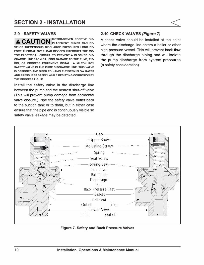
2.10 CHECK VALVES (Figure 7)A check valve should be installed at the point where the discharge line enters a boiler or other high-pressure vessel. This will prevent back flow through the discharge piping and will isolate the pump discharge from system pressures (a safety consideration).
Figure 7. Safety and Back Pressure Valves
SECTION 2 - INSTALLATION

11Installation, Operations & Maintenance Manual
2.11 SHUT-OFF VALVESProvide shut-off valves in both suction and discharge lines next to the pump. Locate discharge line shut-off valve downstream from the inlet connection of the safety valve. Figure 8 shows recommended valve locations.
2.12 SERVICE CONNECTIONS
2.12.1 Pump DriveCheck the nameplate data on the pump drive motor and insure proper power supply is available before making any connections.The preferred motor shaft rotation is shown by an arrow on the drive side flange of the pump. Running the motor in the indicated direction minimizes the potential for damage to the drive. If running in the opposite direction is required, contact the Milton Roy service department for recommendations.For drives other than constant speed electric motors, refer to manufacturer’s instructions and service information included with pump.
Figure 8. Recommended Valve Locations
SECTION 2 - INSTALLATION

12 Installation, Operations & Maintenance Manual
2.12.2 StuffingBoxThe stuffing box is designed to handle most clear, free-flowing liquids; however, liquids w i th suspended so l i ds and ab ras i ves (e.g., certain slurry and phosphate solutions) tend to precipitate in the packing, causing abnormal wear on packing and plunger. An internal flushing connection used with a V- or Chevron-type packing will minimize this tendency and increase packing and plunger life in these applications. (For abrasive slurry applications, ball-check valve cartridges should be installed remote from pump liquid end. Contact Milton Roy for full details.)To connect for internal flushing, remove the stuffing box grease fitting and connect the stuffing box to a source of water (or other compatible liquid) at 25 to 50 psig (172 to 345 kPa) above suction pressure. Since only a few drops per minute are necessary, small diameter tubing will suffice. Install a 1/8” or 1/4” NPT stainless steel aircraft hydraulic system check valve on the flush line right next to the stuffing box connection to keep the process liquid from backing up through the flush line if the packing should fail. A 1/8” or 1/4” (3.2 or 6.4 mm) needle valve should be included for controlling the flushing liquid flow rate. The Milroyal® C can be fitted at the factory or in the field with a Swagelok® elbow and tubing to exit through the pump housing for connection to a flushing line. Contact your Milton Roy representative to order these two parts.Through flush connections to carry hazardous or undesirable fluids from the stuffing box can be provided for by drilling and tapping the stuffing box during manufacture. In these installations, the flushing liquid is piped away from the stuffing box to a drain or other suitable disposal point. For specific instructions concerning field installation of through flushing, consult Milton Roy and provide full details of the application.
2.12.3 DrainsProvide drains convenient to the pump so that any leakage of hazardous fluids may be diverted to suitable container or area. The pump catchall area (beneath the small top cover) is provided with a hole drilled and tapped to receive piping for drainage.
2.12.4 Auxiliary (Accessory) EquipmentService connections for auxiliary or accessory electrical equipment should be determined by referring to wiring diagrams, instruction manuals, and the data plate furnished with the equipment. Air-operated equipment should normally be supplied with two sources of air. The power elements require a standard 60 psig (414 kPa) (80-100 psig (552-690 kPa) at compressor) plant air supply (however, an 80 psig (552 kPa) supply (90-100 psig (621-690 kPa) at compressor) is recommended to ensure maximum performance under all conditions). Instrument air should be supplied from a control instrument or from a manual air pressure regulator furnished with 30 psig (207 kPa) service.
SECTION 2 - INSTALLATION

13Installation, Operations & Maintenance Manual
3.1 INITIAL START-UPRemove covers (6083 and 6085) from top of pump casing and check that interior is free of debris. Reinstall catchall cover (6085). Install oil cleaning magnet (12) over the oil pump intake hole on the underside of the crosshead guide section of the pump casing (see Assembly Drawing, Figure 12 for magnet location). The magnet is bagged with other loose parts shipped in the catchall of the pump. Check that all mounting bolts are tight, piping is installed properly, and the discharge line is open. Fill the pump casing with the lubricant supplied with the pump; fill to the bottom of the oil level plug which is located at the level of the crosshead (12- 1/2” above the housing feet). Pour lubricant into the casing over the bearings and gear set. (refill amount shown below). Replace cover (6083) over the oil sump.
NOTE: Because gear oil viscosity increases as the ambient temperature decreases, you must choose a gear oil appropriate for both the ambient and operating temperatures. Operating temperatures are typically 75°F higher than ambient temperatures. See below for oil recommendations.
Connect pump motor for clockwise rotation as indicated by arrow (8002) on pump casing.
3.2 OIL SPECIFICATIONSGEAR LUBRICANTS
Operating Oil Temperature* Type Oil Recommended
-30°F to 250°F Mobil SHC 634 Synthetic, ISO 460
-10°F to 40°F Mobil Gear 629, ISO 15015°F to 125°F AGMA #7 Comp., ISO 460
*Maximum Oil Temperature 250°F. The nominal capacity of the Milroyal® C housing is 80 pints (44 liters).
Food Grade Equivalent
15°F to 125°F OnlyNevastane EP 460
HYDRAULIC FLUIDSOperation Type Oil Recommended
HPD Liquid End & Disc Diaphragm Zurnpreen 15A, ISO 32
Food Grade Equivalent Nevastane AW32
3.3 INITIAL ADJUSTMENTS
3.3.1 Micrometer Capacity ControlTo adjust pump capacity, loosen the stroke locking screw (110, Figure 12) in the casing above the micrometer-adjust hand knob (490), and turn the hand knob until the desired capacity percentage is just visible on the stroke indicator plate (95). Then tighten the locking screw to maintain capacity setting.
3.3.2 Electric Capacity ControlAn Electric Capacity Control may be mounted on the pump housing in place of the micrometer-adjust hand knob. This accessory adjusts stroke length in response to manual or automatic electric signals from process control instruments. Electric Capacity Control is described in a separate Instruction Manual (53870).
3.3.3 Pneumatic Capacity ControlPneumatic Capacity Control may be mounted on the pump housing in place of the micrometer-adjust hand knob. This accessory adjusts stroke length in response to pneumatic signals from a remotely located control unit. Pneumatic Capacity Control is described in a separate Instruction Manual.
3.3.4 Speed Capacity ControlMilroyal®’ s may be fitted with variable-speed motors to provide capacity control through adjustments in drive speed. Such motors and control accessories are available as options from Milton Roy(54269).
SECTION 3 - OPERATION
14 Installation, Operations & Maintenance Manual
3.3.5 Capacity CalibrationAfter the first 12 hours of operation, the pump may be tested and calibrated to find the exact pump capacity under specific operating conditions.Usually, calibrating the pump at only 100, 50, and 10 percent capacity settings is enough to indicate pump performance throughout the adjustment range.The pump can be calibrated by one of two methods carried out in a given time:1. Measure the decrease in liquid level pumped
from a calibrated vessel.2. Collect and measure pumped liquid at the
pump discharge port. (It may be necessary to create discharge head at the liquid take-off point; otherwise pump will not operate properly. See Section 2 for ways to do this.)
The first method is recommended for hazardous liquids because it eliminates operator contact with the liquid.
3.4 FILLING PUMP SYSTEMIt is especially important that pump suction and discharge lines be free of entrained air. To ensure this condition, operate the pump under no discharge pressure and fill the entire pumping system with liquid before starting pressure tests.If the pump is idle for long periods, temperature changes in the process liquid may produce air in the system. To discharge the air, install a valve in the discharge line which will allow the process liquid to be pumped to exhaust when starting the pump.
3.5 PREVENTATIVE MAINTENANCEMilroyal® C pumps are carefully designed, manufactured, assembled, and quality tested to give reliable service with minimal maintenance. However, a dai ly maintenance check is recommended to visually confirm proper operation of the pump.
3.5.1 DriveCheck gear drive oil level monthly and add oil as required.Change gear drive lubricant and clean magnetic filter below crosshead chamber every six months or after every 2500 hours of operation, whichever occurs first. (This may be scheduled with seasonal oil changes.)
3.5.2 MotorLubricate drive motor annually or according to motor manufacturer’s instructions.
3.5.3 Check ValvesCheck valve assemblies are designed to be self-cleaning and should seldom need servicing. Fouled check valves can usually be cleaned by pumping a hot detergent solution for 15 minutes, followed by water flushing.
SECTION 3 - OPERATION

15Installation, Operations & Maintenance Manual
4.1 SPARE PARTSThe spare parts listed in Table 1 should be stocked for each pump to prevent serious delays in repairs.Parts orders must include the following information:1. Quantity (in this manual)2. Part number (in this manual)3. Part description (in this manual)4. Pump serial number (on pump nameplate)5. Full model number (on pump nameplate)Always include the serial and model numbers in all correspondence regarding the unit.
Drawing Location
ReferenceDescription Qty.
Req.
- Plunger 1375 Connecting Rod Assembly 1310 Conical Sleeve Bearings 2104 Lead Screw Lock Inserts 2250 Gear Set 1480 Crosshead Seal 1355 Worm Shaft Bearings 2
PARTS KIT 328 Tool Kit 1
4.2 RETURNING UNITS TO THE FACTORYPumps will not be accepted for repair without a Return Mater ia l Author izat ion (RMA), available from the Factory Repair Department. Pumps returned to the Factory for repairs should be clearly labeled to indicate the liquid being pumped. Process liquid should be flushed from liquid end before pump is shipped. These safety precautions will aid the troubleshooting and repair procedure and preclude injury to repair personnel from corrosive residue in pump liquid end. Safety Data Sheet must accompany all returns.All inquiries or parts orders should be addressed to your local Milton Roy representative or sent to www.miltonroy.com.
Table 1. Spare Parts
WWW.MILTONROY.COM
PRODUCTCODESERIALNUMBERRATEDCAPACITYRATEDPRESSURE
4.3 DISASSEMBLYThe pump may be dismant led for parts replacement through the following procedures. (Numbers in parentheses are drawing location numbers found on the parts list and drive drawing, Figures 10,11 & 12)
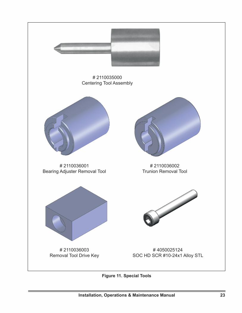
4.3.1 Pump DriveThe following special tools (PARTS KIT 328) will be required for disassembling the pump drive (crosshead and gear housing):#2110035000 Centering tool assembly#2110036002 Trunion removal tool#2110036001 Bearing adjuster removal tool#2110036003 Removal tool drive key#4050025124 SOC HD SCR#10-24X1 Alloy STL
Figure 9. Pump Nameplate
SECTION 4 - MAINTENANCE

16 Installation, Operations & Maintenance Manual
4.3.2 Remove the crosshead from the pump as follows (refer to figures 10,11 & 12):1. Disconnect motor power supply.2. Remove covers (6083 and 6085). Drain oil from
pump casing.3. Loosen plunger adapter, shown in the liquid end
manual.4. Remove liquid end from pump drive.5. Set stroke at 20% and rotate worm until crank
is horizontal. Loosen connecting rod (375) set screws. (Use wrench #2110036003).
6. Loosen sliding shoe nut (391) and remove sliding shoe set screw (405) from sliding shoe (385).
7. Slowly remove crosshead assembly from liquid end side of pump. Be careful not to lose sliding shoe (in crosshead slot). Take care as well not to damage crosshead oil seal (480).
4.3.3 Remove gear housing from pump drive as follows:1. Disconnect motor power supply.2. Drain oil from pump casing.3. Loosen connecting rod (375) set screws
and unscrew tension bearing on end of connecting rod from the crank (220). (Use wrench #2110036003).
4. Unbolt and remove motor and motor adapter (455) from pump casing (55).
5. Set capacity adjustment to 0% stroke.6. Using wrench #2110036001 remove bearing
adjuster (431).7. Loosen the trunnion thread lock set screws.8. Support gear housing assembly in position.
Remove motor side trunnion (330) with wrench #2110036002. Press tapered roller bearing cup from trunnion and remove worm shaft oil seal (421).
9. Withdraw worm shaft from casing. (Bearing cones will come away with shaft; remaining bearing cup may stay in trunnion still in casing).
10. Remove second trunnion in same manner as motor side trunnion. Pull bearing cup from trunnion.
11. Remove nylon thread lock inserts by tightening the trunnion thread lock set screws until the inserts drop through the trunnion bores; then remove the set screws.
12. Lift gear housing (200) from pump casing. To disassemble gear housing assembly, remove crank nut (280) from crank shaft (220) and pull components from crank shaft.
13. Back OFF stroke locking screw (110). Turn stroke adjustment screw (102) counterclockwise to remove it from pump casing. If the stroke adjustment screw is removed, its O-ring seal (103) should be replaced.
SECTION 4 - MAINTENANCE
17Installation, Operations & Maintenance Manual
SECTION 4 - MAINTENANCE
4.4 REASSEMBLY
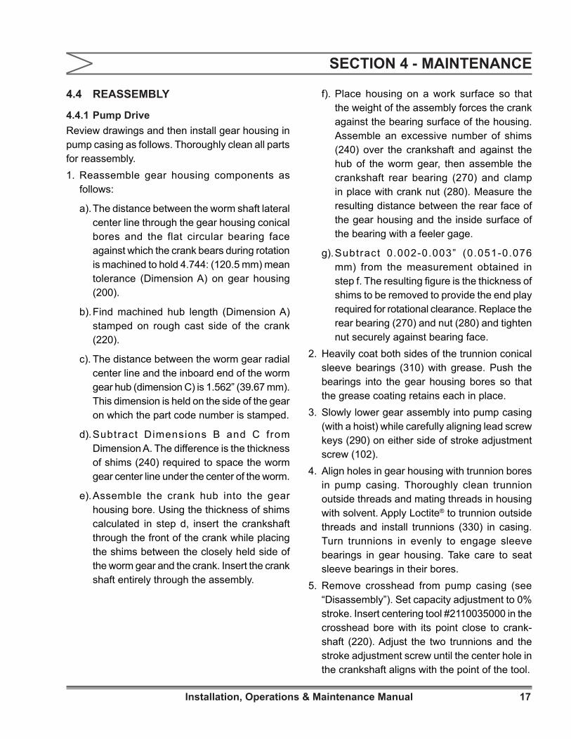
4.4.1 Pump DriveReview drawings and then install gear housing in pump casing as follows. Thoroughly clean all parts for reassembly.1. Reassemble gear housing components as
follows:
a). The distance between the worm shaft lateral center line through the gear housing conical bores and the flat circular bearing face against which the crank bears during rotation is machined to hold 4.744: (120.5 mm) mean tolerance (Dimension A) on gear housing (200).
b). Find machined hub length (Dimension A) stamped on rough cast side of the crank (220).
c). The distance between the worm gear radial center line and the inboard end of the worm gear hub (dimension C) is 1.562” (39.67 mm). This dimension is held on the side of the gear on which the part code number is stamped.
d). Subtract Dimensions B and C from Dimension A. The difference is the thickness of shims (240) required to space the worm gear center line under the center of the worm.
e). Assemble the crank hub into the gear housing bore. Using the thickness of shims calculated in step d, insert the crankshaft through the front of the crank while placing the shims between the closely held side of the worm gear and the crank. Insert the crank shaft entirely through the assembly.
f). Place housing on a work surface so that the weight of the assembly forces the crank against the bearing surface of the housing. Assemble an excessive number of shims (240) over the crankshaft and against the hub of the worm gear, then assemble the crankshaft rear bearing (270) and clamp in place with crank nut (280). Measure the resulting distance between the rear face of the gear housing and the inside surface of the bearing with a feeler gage.
g). Subtract 0.002-0.003” (0.051-0.076 mm) from the measurement obtained in step f. The resulting figure is the thickness of shims to be removed to provide the end play required for rotational clearance. Replace the rear bearing (270) and nut (280) and tighten nut securely against bearing face.
2. Heavily coat both sides of the trunnion conical sleeve bearings (310) with grease. Push the bearings into the gear housing bores so that the grease coating retains each in place.
3. Slowly lower gear assembly into pump casing (with a hoist) while carefully aligning lead screw keys (290) on either side of stroke adjustment screw (102).
4. Align holes in gear housing with trunnion bores in pump casing. Thoroughly clean trunnion outside threads and mating threads in housing with solvent. Apply Loctite® to trunnion outside threads and install trunnions (330) in casing. Turn trunnions in evenly to engage sleeve bearings in gear housing. Take care to seat sleeve bearings in their bores.
5. Remove crosshead from pump casing (see “Disassembly”). Set capacity adjustment to 0% stroke. Insert centering tool #2110035000 in the crosshead bore with its point close to crank-shaft (220). Adjust the two trunnions and the stroke adjustment screw until the center hole in the crankshaft aligns with the point of the tool.

18 Installation, Operations & Maintenance Manual
6. Using wrench #2110036002 and adapter #5411-001-002, alternately tighten trunnions until each is torqued to 150 ft.-lb. (203 N-m) and gear housing is still centered as in step 5.
7. Apply Loctite® sparingly to bearing cup outside diameters. Install bearing cup in closed trunnion and install the worm shaft with bearing cone seated in bearing cup in trunnion. Install motor side bearing cup in open trunnion.
8. Press oil seal (421) into bearing adjuster (431).
9. Ensure bearing adjuster threads and inside threads of open trunnion are completely cleaned of grease. Apply Loctite® sparingly to bearing adjuster outside thread and install bearing adjuster with wrench #2110036001. Be careful not to cut oil seal on shaft keyway edges. Ensure proper gear set tooth engagement and bearing seating by rotating worm while tightening bearing adjuster until snug. After bearing cups are seated, back out bearing adjuster 1/2 turn, then tighten to allow only 0.002- 0.003” (0.051-0.076 mm) lateral running clearance for worm shaft (check with dial indicator from side of pump casing to end of worm shaft).
10. Now let pump sit undisturbed for at least eight hours at 70°F to allow Loctite® to set up.
11. After Loctite® has hardened, coat motor adapter flange bolt threads with liquid sealing compound (e.g., Permatex® #2, non-hardening type) and install motor and motor adapter (455) to pump casing.
4.4.2 Reassemble crosshead in casing as follows:1. Make certain crosshead ball-check is in place
in bottom of crosshead bore. Then, with sliding shoe (385) in crosshead keyway, install crosshead into crosshead bore, aligning sliding shoe with the hole for its set screw.
2. Install sliding shoe set screw (405) in place in casing. Tighten set screw till its dog point seats in the sliding shoe against the crosshead, then back out the set screw 1/4 turn to allow free lateral movement of the crosshead. Lock set screw in place with locknut (391).
3. Set stroke adjustment at 20%. Position crank (220) horizontal and move the crosshead toward the crank so that connecting rod ball can seat in the crank bearing.
4. Thread connecting rod tension bearing into crank arm. Tighten the tension bearing to seat the connecting rod ball in the crank arm. (Use wrench #2110036003).
5. Loosen the tension bearing and retighten till connecting rod is just free enough to rotate with fingers.
6. Tighten both connecting rod set screws.7. Install liquid end to pump drive.
SECTION 4 - MAINTENANCE

19Installation, Operations & Maintenance Manual
SYMPTOMS POSSIBLE CAUSE REMEDY
No delivery.
• Liquid level is low. • Add liquid.• Blocked discharge line. • Clear line.• Liquid is frozen. • Thaw liquid through pumping system.• Fuse is blown. Replace fuse. • Replace fuse.
• Open thermal overload device in starter. • Reset device.
• Broken wire. • Locate and repair.
• Low voltage. • Investigate and correct (wiring may be too light).
• Pump not primed.• Allow suction line and pump head to fill with liquid before pumping against pressure.
Insufficientdelivery.
• Incorrect capacity adjustment. • Readjust capacity setting.
• Incorrect pump speed. • Match line voltage and frequency to pump motor data plate.
• Starved suction. • Increase piping size or suction head.• Leaky suction piping. • Repair piping.• High suction lift. • Rearrange equipment to decrease lift.• Liquid near boiling. • Cool liquid or increase suction head.• Leaky packing. • Adjust or replace packing.• Leaky safety valve in discharge line. • Repair or replace safety valve.
• High liquid viscosity. • Reduce viscosity (e.g.,heat or dilute liquid).
• Worn or dirty check valve seats. • Clean or replace.
Erratic pump delivery.
• Leaky suction piping. • Repair piping.• Leaky packing. • Adjust or replace packing.• Leaky safety valve. • Repair or replace valve.
• Insufficient suction head. • Raise suction tank level or pressurize tank.
• Liquid near boiling. • Cool liquid or increase suction head.• Worn or dirty valve seats. • Clean or replace.• Clogged or dirty line strainer. • Clean strainer.
SECTION 5 - TROUBLESHOOTING GUIDE
20 Installation, Operations & Maintenance Manual
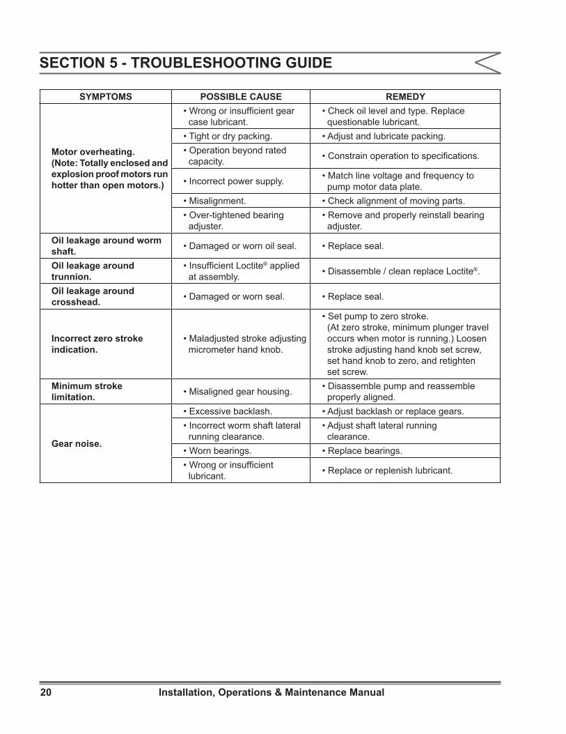
Motor overheating. (Note: Totally enclosed and explosion proof motors run hotter than open motors.)
• Wrong or insufficient gear case lubricant.
• Check oil level and type. Replace questionable lubricant.
• Tight or dry packing. • Adjust and lubricate packing.• Operation beyond rated capacity. • Constrain operation to specifications.
• Incorrect power supply. • Match line voltage and frequency to pump motor data plate.
• Misalignment. • Check alignment of moving parts.• Over-tightened bearing adjuster.
• Remove and properly reinstall bearing adjuster.
Oil leakage around worm shaft. • Damaged or worn oil seal. • Replace seal.
Oil leakage around trunnion.
• Insufficient Loctite® applied at assembly. • Disassemble / clean replace Loctite®.
Oil leakage around crosshead. • Damaged or worn seal. • Replace seal.
Incorrect zero stroke indication.
• Maladjusted stroke adjusting micrometer hand knob.
• Set pump to zero stroke. (At zero stroke, minimum plunger travel occurs when motor is running.) Loosen stroke adjusting hand knob set screw, set hand knob to zero, and retighten set screw.
Minimum stroke limitation. • Misaligned gear housing. • Disassemble pump and reassemble
properly aligned.
Gear noise.
• Excessive backlash. • Adjust backlash or replace gears.• Incorrect worm shaft lateral running clearance.
• Adjust shaft lateral running clearance.
• Worn bearings. • Replace bearings.• Wrong or insufficient lubricant. • Replace or replenish lubricant.
SYMPTOMS POSSIBLE CAUSE REMEDY
SECTION 5 - TROUBLESHOOTING GUIDE

21Installation, Operations & Maintenance Manual
SECTION 5 - TROUBLESHOOTING GUIDE
Loud knock with each stroke.
• Insufficient torque on trunnions. • Re-torque trunnions.
• Loose crank nut. • Tighten nut.• Loose or worn connecting rod tension bearings. • Tighten or replace bearings.
• Worn conical sleeve bearings. • Replace bearings.
• Excessive gear set wear. • Replace gear set.• Loose clevis. • Tighten clevis.
Rocking gear housing. • Worn stroke adjusting screw or keys. • Replace worn parts.
Crosshead hesitation. • Loose tension bearing. • Remove and inspect connecting; reinstall or replace and secure tension bearing.
Crosshead rotation.• Dog point set screw not seated in crosshead sliding shoe.
• Remove crosshead, examine for scoring; polish smooth and reinstall.
Worn connecting rod bearings.
• Contaminated oil. • Replace worn parts and oil and change oil on schedule.
• Plugged connecting rod. • Clear connecting rod.• Faulty relief valve. • Replace relief valve.• Fouled or missing ball checks in forced feed lubrication system.
• Clean or install ball checks.
SYMPTOMS POSSIBLE CAUSE REMEDY

22 Installation, Operations & Maintenance Manual
Figure 10. Pump Drive Parts
23Installation, Operations & Maintenance Manual
# 2110035000Centering Tool Assembly
# 2110036001Bearing Adjuster Removal Tool
# 4050025124SOC HD SCR #10-24x1 Alloy STL
# 2110036002Trunion Removal Tool
# 2110036003Removal Tool Drive Key
Figure 11. Special Tools
24 Installation, Operations & Maintenance Manual
SECTION 6 - PARTS
6.1 GENERAL1. This section gives information regarding
replaceable components.
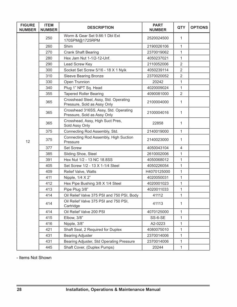
6.2 ILLUSTRATED PARTS LIST1. Figure and Item Number Column
a) The item numbers shown in the detailed parts list correspond to the item numbers appearing on the exploded view illustration. To find an unknown part number, locate the part on the illustration and note the item number. Look for the item number on the detailed parts list. The part number is on the same line. A dash (-) precedes non-illustrated item numbers.
2. Description Column
a) The name of the item is in the description column.
3. Part Number Column
a) The supplier’s part number is listed in the part number column.
4. Material / SPM Column
a) The material used to manufacture the part is listed in the material / SPM column.
b) The strokes per minute is listed for all worm and shaft assemblies in the material / SPM column.
5. Quantity Column
a) The numbers appearing in the quantity column are the total quantity of the listed part required in its immediate assembly.
25Installation, Operations & Maintenance Manual
VIEW A-A
0472
0473
0445
0310
0200
8010
8020
0290
0455
0468
0465
03550330 0431
0450 04210355
0385
0391
0405
0065
0010
0250
0469
Figure 12. Drive End View (DWG 102-2285-000)(Sheet 1 of 2)

26 Installation, Operations & Maintenance Manual
09
18
2
CA
UTI
ON
04656072
0411
041404130412
0090
0468
6085 6090 60830453
0496
0095
8005 8002 8004
A
A
VIEW B-B
HIGH SUCTION PRESSURE
VIEW B-B
RELIEF VALVE
0415
0416
MILROYAL
6075
6080
026002400365
0480
00550250
0280
0080
0270
0108 0106
01100495
0490
0102
0010
0103
0104030002200230
02100375
00310050
0020
0041 0200
0340
0409
STANDARDRELIEF VALVE
VIEW B-B
Figure 12. Drive Side and Top Views (DWG 102-2285-000)(Sheet 2 of 2)

27Installation, Operations & Maintenance Manual
- Items Not Shown
6.3 MILROYAL® C DRIVE.
FIGURE NUMBER
ITEM NUMBER DESCRIPTION PART
NUMBER QTY OPTIONS
12
10 Soc Set Screw CPT 3/8-16 X 3/8” Steel 4050045034 312 Magnet 4060227000 120 Gasket 2250076000 131 Bottom Covers 2810180006 141 Lock Washer 5/16” 4040040028 1250 Hex Head Screw 5/16 X 3/4” 4050017091 12
55 Drive Housing, All HPD, Std. Operating Pressure 2810179301 1
55 Drive Housing, All HPD, High Suction Pressure 2810179401 1
65 Ball 1/2” 440SS 4070014150 180 Plug 1/2” NPT Socket Hex Head, 302SS 4023522000 2
90 1/2” Steel Elbow 150# Threaded, Std. Operating Pressure, 304SS 4020031042 1
95 Stroke Plate 2530009062 1102 Lead Screw, Steel 2560040006 1103 O-Ring for Lead Screw 4080095111 1104 Lock Insert-Touches Lead Screw 2430028274 1
106 Locking Insert-Touches Locking Screw(Item 110) 2430031039 1
108 O-Ring 2-012 Buna N 70 Duro 4089996017 1110 Locking Screw, Steel 2560012006 1200 Gear Housing Mod C 2810167001 1210 Crank Shaft 2680012006 1220 Crank 2160003062 1230 Crank Key 2110025006 1240 Arbor Spacers 4040115011 1240 Arbor Spacers 4040115031 1240 Shim Wash Keyed 2.25 X 3.25 X 0.01 4040115101 1250 Worm & Gear Set 15.5:1 Dbl Ext 2520024400 1250 Worm & Gear Set 12.5:1 Dbl Ext 2520024100 1250 Worm & Gear Set 20.5:1 Dbl Ext 2520024500 1250 Worm & Gear Set 24.5:1 Dbl Ext 2520024200 1250 Worm & Gear Set 40:1 Dbl Ext 2520024600 1250 Worm & Gear Set 9.66:1 Dbl Ext 2520024000 1
28 Installation, Operations & Maintenance Manual
- Items Not Shown
12
250 Worm & Gear Set 9.66:1 Dbl Ext 170SPM@1725RPM 2520024500 1
260 Shim 2190026106 1270 Crank Shaft Bearing 2370019062 1280 Hex Jam Nut 1-1/2-12-Unf. 4050237021 1290 Lead Screw Key 2110052006 2300 Socket Set Screw 5/16 - 18 X 1 Nyik 4050239114 2310 Sleeve Bearing Bronze 2370020052 2330 Open Trunnion 20242 1340 Plug 1” NPT Sq. Head 4020009024 1355 Tapered Roller Bearing 4090081000 2
365 Crosshead Steel, Assy, Std. Operating Pressure, Sold as Assy Only 2100004000 1
365 Crosshead 316SS, Assy, Std. Operating Pressure, Sold as Assy Only 2100004016 1
365 Crosshead, Assy, High Suct Pres,Sold Assy Only 22858 1
375 Connecting Rod Assembly, Std. 2140019000 1
375 Connecting Rod Assembly, High Suction Pressure 2140023000 1
377 Set Screw 4050043104 4385 Sliding Shoe, Steel 2610002006 1391 Hex Nut 1/2 - 13 NC 18.8SS 4050068012 1405 Set Screw 1/2 - 13 X 1-1/4 Steel 4050226054 1409 Relief Valve, Watts H4070125000 1411 Nipple, 1/4 X 2” 4020050031 1412 Hex Pipe Bushing 3/8 X 1/4 Steel 4020001023 1413 Pipe Plug 3/8” 4020011033 1414 Oil Relief Valve 375 PSI and 750 PSI, Body 41112 1
414 Oil Relief Valve 375 PSI and 750 PSI, Cartridge 41113 1
414 Oil Relief Valve 200 PSI 4070125000 1415 Elbow, 3/8” SS-6-SE 1416 Nipple, 3/8” A2-0223 1421 Shaft Seal, 2 Required for Duplex 4080075010 1431 Bearing Adjuster 2370014006 1431 Bearing Adjuster, Std Operating Pressure 2370014006 1445 Shaft Cover, (Duplex Pumps) 20244 1
FIGURE NUMBER
ITEM NUMBER DESCRIPTION PART
NUMBER QTY OPTIONS

29Installation, Operations & Maintenance Manual
12
450 Coupling L-100 1-3/16 X 1-3/16,(Duplex Pumps) 4100068070 1
450 Coupling L-100 1-3/16 X 5/8,(Frame 56C Mount) 4100068230 1
450 Coupling L-100 7/8 X 1-3/16, (Frame 143/145TC 182/184C) 4100068200 1
450 Coupling L-100 1-3/16 X 1-1/8,(Frame 182/184TC) 4100068240 1
450 Coupling L-100 1-3/16 X 1-3/8,(Frame 213/215TC) 4100068250 1
450 Coupling L-150 1-3/16 X 24mm,(Frame Metric 90) 4100129080 1
453 Crank Key 2110018406 1455 Flange Adapter, (Frame 56C Mount) 2720035001 1
455 Flange Adapter,(Frame 143/145TC, 182/184C) 2720035001 1
455 Flange Adapter,(Frame 182/184TC, 213/215TC) 2720036101 1
455 Flange Adapter, (Frame Metric 90) 2720133000 1455 Flange Adapter, (Frame Metric 100) 3050331030 1455 Flange Adapter, (Frame Metric 132) 3050331040 1
465 Spring Lock Washer, 5/8 18.8SS,(All Frames) 4040044022 4
468 Hex Head Screw, 5/8 - 11 X 1, Steel, (Duplex Pump Coupling Guard) 4050021111 4
468 Hex Head Screw, 5/8 - 11 X 2, Steel, (All Frames) 4050021161 4
472 Spring Lock Washer, 3/8 18.8SS (Frame 56C Mount) 4040041022 4
472 Spring Lock Washer, 3/8 18.8SS, (Frame 143/145TC 182/184C) 4040041022 4
472 Spring Lock Washer, 1/2 18.8SS, (Frame 182/184TC, 213/215TC) 4040043022 4
472 Spring Lock Washer, 10mm 18.8SS, (Frame Metric 90) 64340009015 4
473 Hex Head Screw, 3/8 - 16 X 1-1/4, (Frame 56C Mount) 4050018136 4
- Items Not Shown
FIGURE NUMBER
ITEM NUMBER DESCRIPTION PART
NUMBER QTY OPTIONS

30 Installation, Operations & Maintenance Manual
- Items Not Shown
12
473 Hex Head Screw, 3/8 - 16 X 1-1/4, (Frame 143/145TC 182/184C) 4050018136 4
473 Hex Head Screw, 1/2 - 13 X 1-1/24, (Frame 182/184TC, 213/215TC) 4050020144 4
473 Hex Head Screw, M10 X 30 8.8,(Frame Metric 90) 64350035694 4
480 Oil Seal, Crosshead 4080035010 1490 Stroke Adjust Knob 2550038015 1495 Socket Set Screw, 3/8 - 16 X 1/2, Steel 40073 2496 Socket Set Screw, 3/8 - 16 X 1-1/2 4050045114 1
6072 Coupling Guard, Std Operating Pressure 2490065006 16075 Nameplate, Milroyal® B and C 20662 16080 Stick Screw 5/32 Steel 4050280000 46083 Cover (Main) 51285 16085 Cover Assembly Catchall 2810279030 16090 Pan Head Screw 1/4 - 20 X 3/4 18.8SS 4050213072 108002 Arrow, Motor Rotation 4120007010 28004 Capacity Adjustment Lock Decal 2530022000 18005 HPD Caution Sticker 2530007099 18010 Gear Oil Agma 7, 12.5 Gallons 30620 1
- Allen Wrenches 4130004050 1
FIGURE NUMBER
ITEM NUMBER DESCRIPTION PART
NUMBER QTY OPTIONS

31Installation, Operations & Maintenance Manual
SERVICE RECORD
Pump Model No : Pump Serial No : Liquid Pumped : This page is designed as an aid in maintaining the Milroyal® pump. Common service operations are listed here with general recommendations based on Service Department field experience.Gear Drive Lubricant. Monthly inspection of level and condition is recommended. Also recommended is replacement of the lubricant 90 days after the pump is first placed in service. Thereafter, change the lubricant at 6 month or 2500 hour intervals (whichever occurs first).Supply Tank and Piping. Clean and flush annually.Suction Line Strainer. Clean as required.Ball-Check Valves. Flush with clean liquid as often as necessary to maintain full metering accuracy.
SERVICE OPERATOR DATE HOURS REMARKS

32 Installation, Operations & Maintenance Manual
1 atmosphere Equals1.0333 kilograms/ square centimeter101.33 kilopascals1.0135 bars
1 Btu/hour Equals 0.2928 WattsDegrees Fahrenheit Equals 1.8° Celsius + 321 Angler degree Equals 7.45 square millimeters/ second
1 foot Equals30.48 centimeters12 inches
1 Ford cup #4 Equals 3.76 square millimeters/ second
1 gallon (U.S.) Equals
0.1337 cubic feet0.8333 Imperial gallons3.785 liters4 quarts
1 gallon/hour (U.S.) Equals0.003785 cubic meters/ hour0.002228 cubic feet/ minute
1 horsepower Equals 745.7 Watts1 inch Equals 2.540 centimeters
1 inch of mercury Equals0.03442 kilograms/ square centimeter3376.5 Pascals0.4897 pounds/ square inch
1 pint (liquid) Equals0.4732liters16 ounces
1 pound/square inch Equals
0.06804 atmospheres0.06897 bars0.07029 kilograms/ square centimeter6894.8 Pascals
1 Redwood Admiralty Equals 2.340 square millimeters/ second1 Redwood Standard Equals 0.237 square millimeters/ second1 Saybolt Furol Equals 2.16 square millimeters/ second1 Saybolt Second Universal Equals 0.216 square millimeters/ second
TABLE OF EQUIVALENTS


MILROYAL® is a registered trademark of Milton Roy, LLC.© 2015 Milton Roy, LLC.
[email protected] www.miltonroy.com
We are a proud member of Accudyne Industries, a leading global provider of precision-engineered, process-critical, and technologically advanced flow control systems and industrial compressors. Delivering consistently high levels of performance, we enable customers in the most important industries and harshest environments around the worldto accomplish their missions.