microwave optics - suny cortland - faculty and...
TRANSCRIPT
IncludesTeacher's Notes
andTypical
Experiment Results
P^
Instruction Manual andExperiment Guide forthe PASCO scientificModel WA-9314B
0I2-04630G
MICROWAVE OPTICS
ly-wtf*(g) 10101 Foothills Blvd. •Roseville, CA 95678-9011 USA
Phone (916) 786-3800 • FAX (916) 786-8905 • web:www.pasco.com
012-04630G
Table of Contents
Section PageCopyright, Warranty, and Equipment Return ii
Introduction 1
Equipment 1
Initial Setup 3
Accessory Equipment 3
Assembling Equipment for Experiments 5
Experiments
-> Experiment 1: Introduction to the System 7
"* Experiment 2: Reflection 11
Experiment 3: Standing Waves - Measuring Wavelengths 13
-> Experiment 4: Refraction Through a Prism 17
-^ Experiment 5: Polarization 19
—=> Experiment 6: Double-Slit Interference 21
Experiment 7: Lloyds Mirror 23
Experiment 8: Fabry-Perot Interferometer 25
Experiment 9: Michelson Interferometer 27
Experiment 10: Fiber Optics 29
Experiment 11: Brewster's Angle 31
—? Experiment 12: Bragg Diffraction 33
Teacher's Guide 35
Appendix 45
Schematic Diagrams 46
Replacement Parts List 47
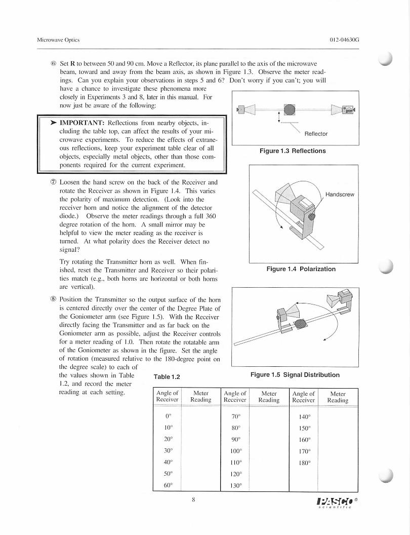
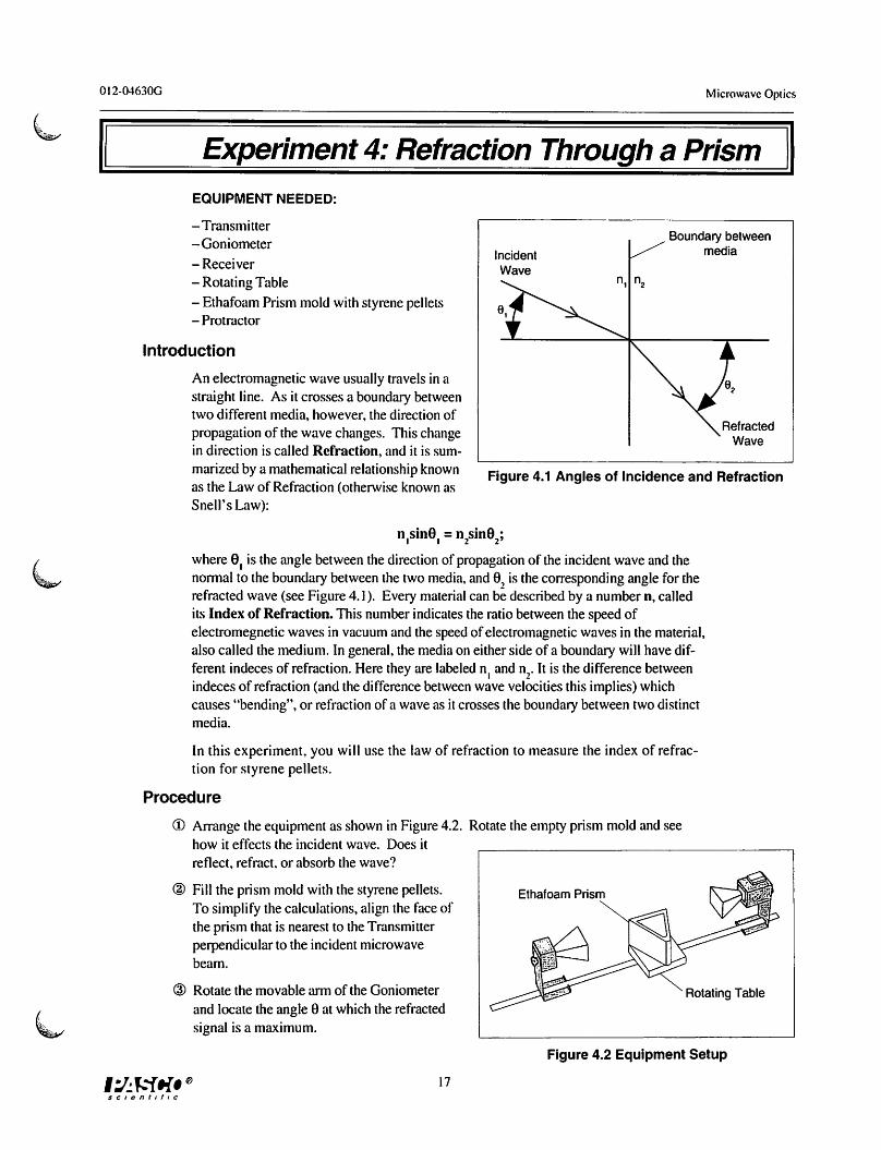
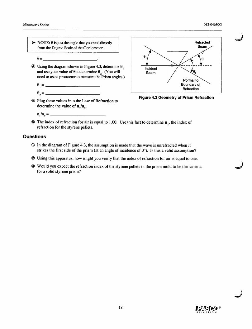
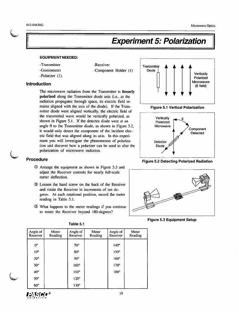
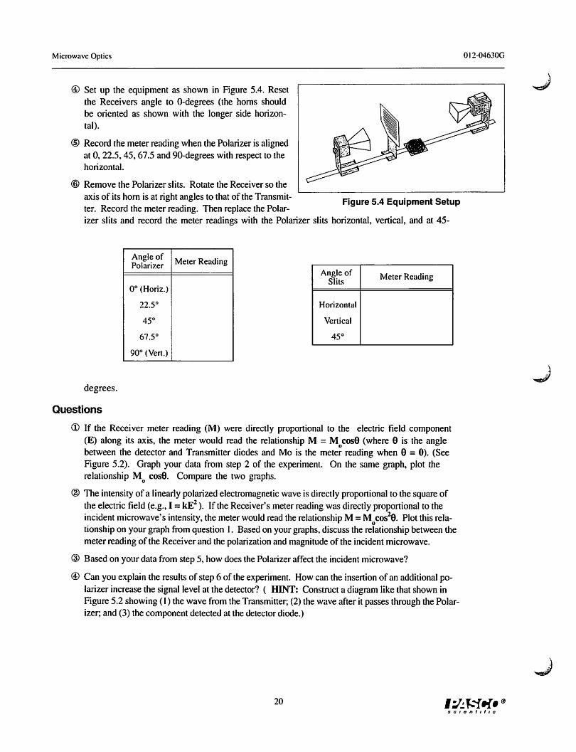
Microwave Optics
Ctf^ > This device complies with Part 15 of the FCC Rules. Operation is subject to the^-r following two conditions:
1. this device may not cause harmful interference.2. this device must accept any interference received, including interference that may
cause undesired operation.
Changes or modifications not expressly approved by Pasco Scientific could void the user's authority to operate the equipment.
scientific
Microwave Optics 0I2-04630G
Copyright, Warranty, and Equipment Return
Please—Feel free to duplicate this manualsubject to the copyright restrictions below.
Copyright Notice
The PASCO scientific 012-04630E Model WA-9314B
Microwave Optics manual is copyrighted and all rightsreserved. However, permission is granted to non-profiteducational institutions for reproduction of any part of themanual providing the reproductions are used only for theirlaboratories and are not sold for profit. Reproductionunder any other circumstances, without the writtenconsent of PASCO scientific, is prohibited.
Limited Warranty
PASCO scientific warrants the product to be free fromdefects in materials and workmanship for a period of oneyear from the date of shipment to the customer. PASCOwill repair or replace at its option any part of the productwhich is deemed to be defective in material or workman
ship. The warranty does not cover damage to the productcaused by abuse or improper use. Determination ofwhether a product failure is the result of a manufacturingdefect or improper use by the customer shall be madesolely by PASCO scientific. Responsibility for the returnof equipment for warranty repair belongs to the customer.Equipment must be properly packed to prevent damageand shipped postage or freight prepaid. (Damage causedby improper packingof the equipment for return shipmentwill not be covered by the warranty.) Shipping costs forreturning the equipment after repair will be paid byPASCO scientific.
Credits
This manual edited by: Dave Griffith
Teacher's guide written by: Eric Ayars
Equipment Return
Should the product have to be returned to PASCOscientific for any reason, notify PASCO scientific byletter,phone, or fax BEFORE returning the product. Uponnotification, the return authorization and shippinginstructions will be promptly issued.
> NOTE: NO EQUIPMENT WILL BEACCEPTED FOR RETURN WITHOUT AN
AUTHORIZATION FROM PASCO.
When returning equipment for repair, the units must bepacked properly.Carriers will not accept responsibility fordamage caused by improper packing. To be certain theunit will not be damaged in shipment, observe the following rules:
(D The packing carton must be strong enough for theitem shipped.
® Make certain there are at least two inches of
packing material between any point on theapparatus and the inside walls of the carton.
(D Make certain that the packing material cannot shiftin the box or become compressed, allowing theinstrument come in contact with the packingcarton.
Address: PASCO scientific
10101 Foothills Blvd.
Roseville, CA 95747-7100
Phone: (916)786-3800
FAX: (916)786-3292
email: [email protected]
web: www.pasco.com
scientific
^J
012-04630G Microwave Optics
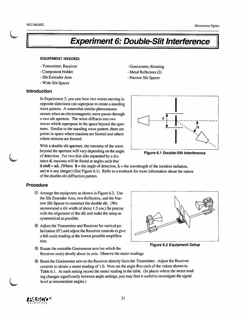
Introduction
There are many advantages to studying optical phenomena at microwave frequencies. Using a 2.85 centimetermicrowave wavelength transforms the scale of the experiment. Microns become centimeters and variables ob
scured by the small scale of traditional optics experimentsare easily seen and manipulated. The PASCO scientificModel WA-9314B Basic Microwave Optics System isdesigned to take full advantage of these educational benefits. The Basic Microwave Optics System comes with a2.85 centimeter wavelength microwave transmitter and areceiver with variable amplification (from IX to 30X).All the accessory equipment needed to investigate a variety of wave phenomena is also included.
This manual describes the operation and maintenance ofthe microwave equipment and also gives detailed instructions for many experiments. These experiments rangefrom quantitative investigations of reflection and refraction to microwave models of the Michelson and Fabry-Perot interferometers. For those who have either the
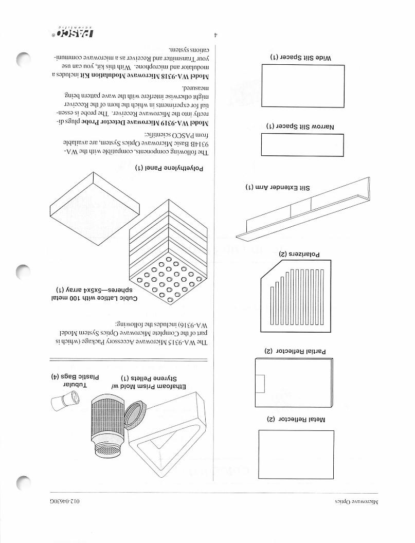
Complete Microwave Optics System (WA-9316) or theMicrowave Accessory Package (WA-9315), the manualdescribes experiments for investigating Bragg diffractionand Brewster's angle.
Equipment
Gunn Diode Transmitter
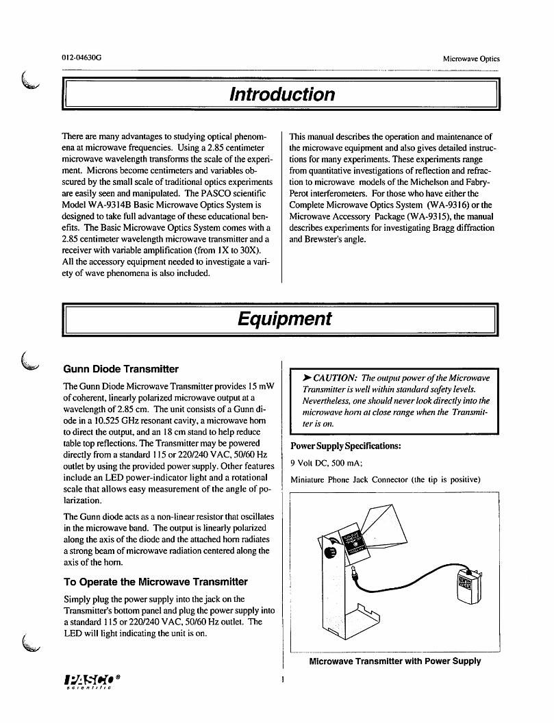
The Gunn Diode Microwave Transmitter provides 15 mWof coherent, linearly polarized microwave output at awavelength of 2.85 cm. The unit consists of a Gunn diode in a 10.525 GHz resonant cavity, a microwave hornto direct the output, and an 18 cm stand to help reducetable top reflections. The Transmitter may be powereddirectly from a standard 115 or 220/240 VAC, 50/60 Hzoutlet by using the provided power supply. Other featuresinclude an LED power-indicator light and a rotationalscale that allows easy measurement of the angle of polarization.
The Gunn diode acts as a non-linear resistor that oscillates
in the microwave band. The output is linearly polarizedalong the axis of the diode and the attached horn radiatesa strong beam of microwave radiation centered along theaxis of the horn.
To Operate the Microwave Transmitter
Simply plug the power supply into thejack on theTransmitter's bottom panel and plug the power supply intoa standard 115 or 220/240 VAC, 50/60 Hz outlet. The
LED will light indicating the unit is on.
scientific
>• CAUTION: Tlwoutputpower ofthe MicrowaveTransmitter is well withinstandardsafety levels.Nevertheless, one shouldnever lookdirectlyintothemicrowavehorn at close range whenthe Transmitter is on.
Power Supply Specifications:
9 Volt DC, 500 mA;
Miniature Phone Jack Connector (the tip is positive)
Microwave Transmitter with Power Supply
Microwave Optics
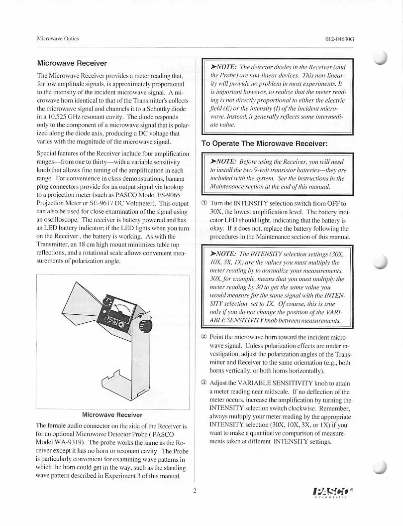
Microwave Receiver
The Microwave Receiver provides a meter reading that,for low amplitude signals, is approximately proportionalto the intensity of the incident microwave signal. A microwave horn identical to that of the Transmitter's collects
the microwave signal and channels it to a Schottky diodein a 10.525 GHz resonant cavity. The diode respondsonly to the component of a microwave signal that is polarized along the diode axis, producing a DC voltage thatvaries with the magnitude of the microwave signal.
Special features of the Receiver include fouramplificationranges—from one to thirty—with a variable sensitivityknob that allows fine tuning of the amplification in eachrange. For convenience in class demonstrations, bananaplug connectors provide foran output signal viahookupto a projection meter (such as PASCO Model ES-9065Projection Meteror SE-9617 DC Voltmeter). Thisoutputcan also be used for close examination of the signal usingan oscilloscope. The receiver is battery powered and hasan LED battery indicator: if the LED lights when you turnon the Receiver. the battery is working. As with theTransmitter, an 18 cm high mount minimizes table topreflections, and a rotational scale allows convenient mea
surements of polarization angle.
Microwave Receiver
The female audio connector on the side of the Receiver is
for an optional Microwave Detector Probe ( PASCOModel WA-9319). The probe works the same as the Receiver except it has no horn or resonant cavity. TheProbeisparticularly convenient forexamining wave patterns inwhich the horn couldget in the way, suchas thestandingwave pattern described in Experiment 3 of this manual.
012-04630G
^•NOTE: The detector diodes in the Receiver (andthe Probe) are non-linear devices. This non-linear
ity will provide no problem in most experiments. Itis important however, to realize that the meter reading is not directly proportional to either the electricfield (E) or the intensity (I) ofthe incident microwave. Instead, it generally reflectssome intermediate value.
To Operate The Microwave Receiver:
>NOTE: Beforeusing the Receiver, you will needto install the two 9-volt transistor batteries—theyareincluded withthe system. See the instructions in theMaintenancesection at the end ofthis manual.
(V Turn the INTENSITY selection switch from OFF to
30X, the lowest amplification level. The battery indicator LED should light, indicating that the battery isokay. If it does not. replace the batter)' following theprocedures in the Maintenance section of this manual.
>NOTE: The INTENSITY selectionsettings (30X,IOX, 3X, IX)arc the values you must multiply themeter reading by to normalize your measurements.SOX, for example, meansthat youmust multiply themeter reading by SO to get the same value youwould measurefor the same signal with the INTENSITY selection set to IX. Of course, this is trueonlyifyoudo notchange theposition ofthe VARIABLE SENSITIVITY knob between measurements.
® Point the microwave horn toward the incident microwave signal. Unless polarization effects are under investigation, adjust the polarizationangles of the Transmitter and Receiver to the same orientation (e.g., bothhorns vertically, or both horns horizontally).
® Adjust the VARIABLE SENSITIVITY knobto attaina meter reading near midscale. If no deflection of themeteroccurs, increase the amplification by turning theINTENSITY selection switch clockwise. Remember,
always multiply your meterreading by theappropriateINTENSITY selection (30X, 10X, 3X, or IX) if youwant to make a quantitative comparison of measurements taken at different INTENSITY settings.
I^KWf
012-04630G Microwave Oplics
Initial Setup
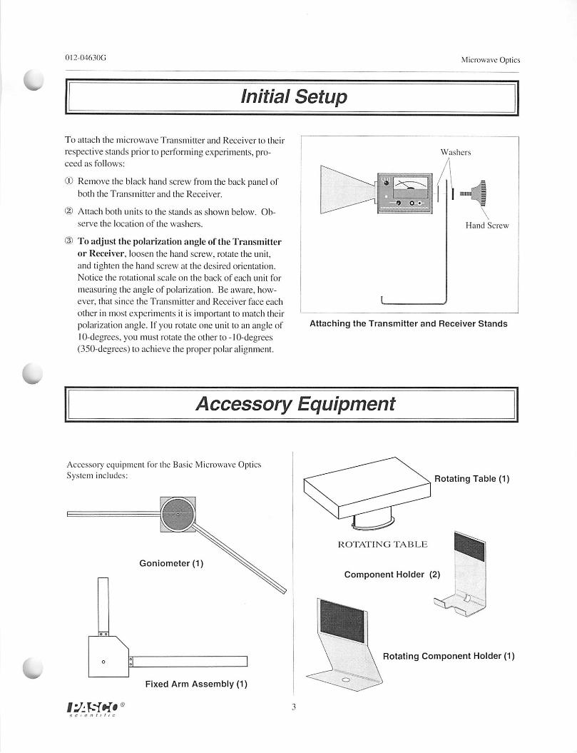
To attach the microwave Transmitter and Receiver to their
respective stands prior to performingexperiments, proceed as follows:
(D Remove theblack hand screw from theback panel ofboth the Transmitter and the Receiver.
® Attach both units to the stands as shown below. Ob
serve the location of the washers.
® To adjust the polarization angleof the Transmitteror Receiver, loosen the hand screw, rotate the unit,and tighten the hand screw at the desired orientation.Notice the rotational scale on the back of each unit for
measuring the angle of polarization. Be aware, however, that since the Transmitter and Receiver face each
other in most experiments it is important to match theirpolarization angle. If you rotate one unit to an angle of10-degrees. you must rotate the other to -10-degrees(350-degrees) to achieve the proper polar alignment.
Washers
1 land Screw
Attaching the Transmitter and Receiver Stands
Accessory Equipment
Accessory equipment for the Basic Microwave OpticsSystem includes:
u
o *
i'JlWi*
Goniometer (1)
Fixed Arm Assembly (1)
Rotating Table (1)
ROTATING TAB LIZ
Component Holder (2)
Rotating Component Holder (1