microwave discharge ion sources - cern main parameters of the related proton drivers are listed in...
TRANSCRIPT

Microwave Discharge Ion Sources
L. CelonaIstituto Nazionale di Fisica Nucleare, Laboratori Nazionali del Sud, Catania, Italy
AbstractThis chapter describes the basic principles, design features and characteris-tics of microwave discharge ion sources. A suitable source for the productionof intense beams for high-power accelerators must satisfy the requirementsof high brightness, stability and reliability. The 2.45 GHz off-resonance mi-crowave discharge sources are ideal devices to generate the required beams, asthey produce multimilliampere beams of protons, deuterons and singly chargedions. A description of different technical designs will be given, analysing theirperformance, with particular attention being paid to the quality of the beam,especially in terms of its emittance.
1 IntroductionThe production of high-current beams is a key requirement for various applications, and this is expectedto increase in coming years, either for industrial applications or for research projects. High-current andhigh-brightness H+ beams can be provided by microwave discharge ion sources (MDISs), which presentmany advantages in terms of compactness, high reliability, ability to operate in continuous-wave (CW) orpulsed mode, reproducibility and low maintenance. Some applications based on intense proton beams [1]are as follows:
– accelerator-driven systems (ADSs) for nuclear waste transmutation and energy production,– radioactive ion beams,– intense neutron spallation sources,– radiation processing, and– neutrino factory.
The main parameters of the related proton drivers are listed in Table 1, while Table 2 shows a listof projects (operating and under construction) using high-current proton beams or intense H− sourceswith low transverse emittance.
Table 1: Proton driver requirements.
Proton driver Energy (GeV) Beam power (MW)ADS: XADS ∼ 0.6 ∼ 5
Ind. burner ∼ 1 ∼ 50Spall. neutron source (ESS) 1.33 5Irradiation facility 1 > 10Neutrino factory (CERN) 2.2 4RIB: ‘one stage’ ∼ 0.2 ∼ 0.1
‘two stage’ ∼ 1 ∼ 5–10
The optimization of beam formation and transport through the low-energy beam transport (LEBT)plays a fundamental role in the provision of a high-quality beam to the accelerator. This is a commonrequirement of the projects reported in Table 2, where emittances at the entrance to the radio frequency
421

Table 2: High-power accelerator requirements.
p/H− mA ms Hz Duty factor (%) π mm mradLEDA p 100 CW CW 100 0.25IPHI p 100 CW CW 100 0.25TRASCO p 30 CW CW 100 0.2ESS p 60/90 2.84 14 4 0.3
SPL H− 50 1.5 50 7.5 0.2SNS H− 50 1 60 6 0.25JKJ H− 30 0.5 50 2.5 0.25
quadrupole (RFQ) of the order of 0.20–0.30 π mm mrad are needed, making it essential to design andtest the ion source and LEBT as a whole. The major challenge of the accelerator front-end is thereforethe preparation of a high-quality beam, with a pulse that is well defined in time and has a small transverseemittance. In the following, a review of the major experiences in the production of intense proton beamsare reported (Table 2) together with future perspectives.
2 Microwave ion source for high-intensity proton production2.1 Historical notesThe history of 2.45 GHz high-current source (HCSs) started about 35 years ago with different sourcedesigns proposed by Sakudo [2] and by Ishikawa et al. [3], especially for industrial applications. Thesources produced remarkable results not only for protons, but also for deuterons and singly chargedlight ions. A simple concept of the microwave discharge source was based on a non-confining magneticfield higher than the resonance field (i.e. 87.5 mT). Sakudo and his collaborators at the Central ResearchLaboratory of Hitachi Limited pioneered the development of high-current microwave ion sources forion implantation [4]. The first Hitachi ion source (see Fig. 1) is composed of a plasma generator, thatis, essentially, a section of coaxial waveguide with an axial magnetic field supplied by three solenoids.The 2.45 GHz microwaves are introduced via a water-cooled antenna connected to the inner conductorof a coaxial-to-rectangular waveguide transition. The magnetic induction is varied along the length ofthe antenna to match the impedance of the plasma-filled chamber to the impedance of the microwaveline [5]. The extraction system is a multiaperture triode with 124 apertures 3 mm in diameter distributedover a 50 mm diameter circle. The sources built by Sakudo’s group were able to supply 2 mA of As+
and 15 mA of B+, and they were successfully adapted to industrial application setups.
The second microwave ion source developed by Sakudo et al. was especially designed to generatea slit-shaped ion beam. The plasma chamber illustrated in Fig. 2 is a tapered ridged waveguide with allbut the volume between the ridges filled with boron nitride. The 2.45 GHz microwaves are introducedthrough a dielectric window from a rectangular waveguide. The electric field between the ridges isrelatively uniform, ensuring a reasonably constant plasma density over the entire length.
A step forward was made by Ishikawa [6], whose design was very compact (chamber diameterwas 50 mm) and the source was able to produce milliampere beams of any species, finding applicationsnot only in ion implantation devices but also for ion beam deposition. The absence of antennas made thisequipment more reliable for long-time operations.
2.2 The CRNL ion sourceIn 1991 a simple and robust design was proposed by Taylor and Mouris at Chalk River National Labora-tory (CRNL; see Fig. 3). This source can be considered as the basis of all the different designs proposed
L. CELONA
422


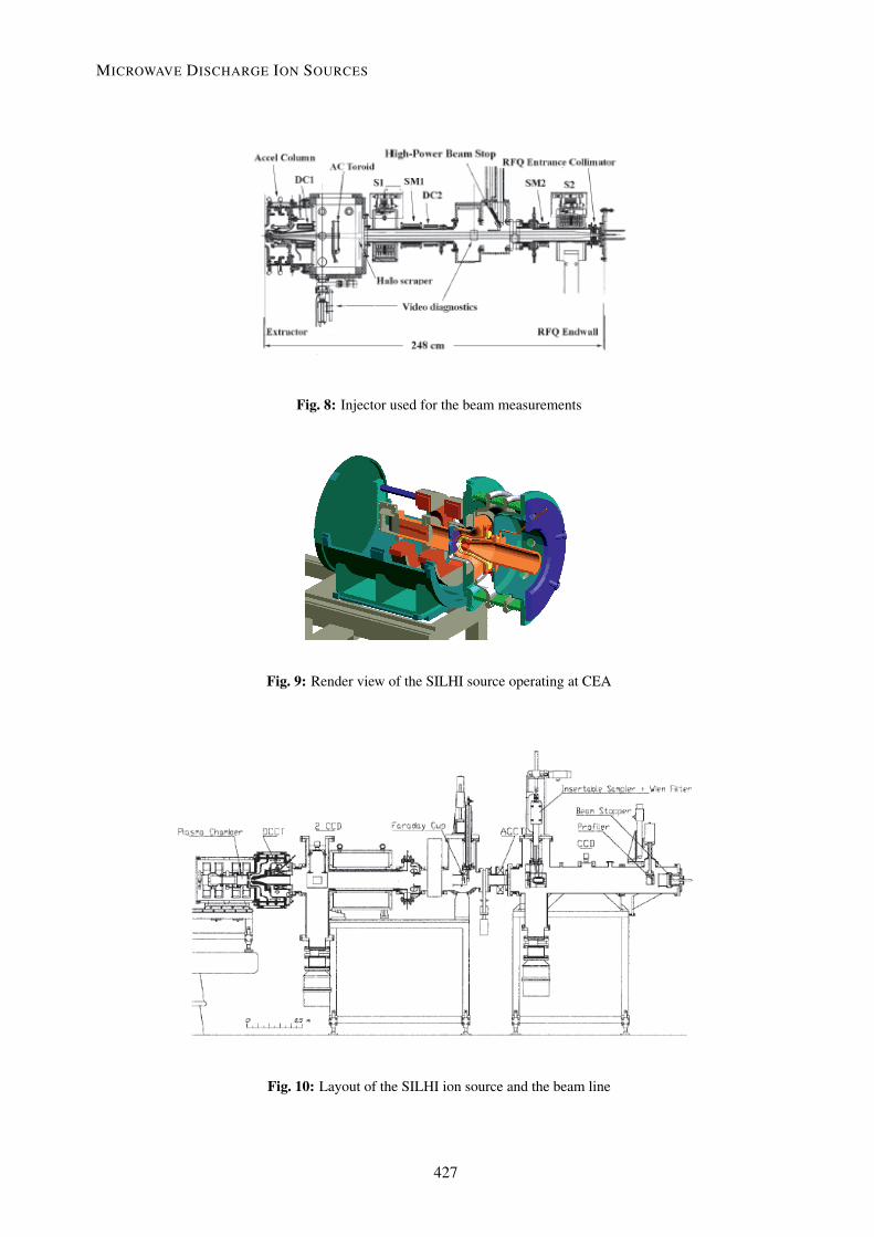

Table 4: SILHI source typical operating parameters.
Parameter ValueTotal beam current 140 mAProton fraction ∼ 85%Beam density 220 mA cm−2
Beam energy 95 keVDischarge RF power, at 2.45 GHz 1.2 kWBeam emittance, at 75 mA 0.1 π mm mradHydrogen mass flow ∼ 2 sccm
2.5 TRASCO Intense Proton Source (TRIPS) at INFN-LNSThe TRIPS ion source [11] has been designed, realized and commissioned at INFN-LNS, within theframework of the TRASCO Project (an R&D programme, the goal of which was the design of an accel-erator driving system (ADS) for nuclear waste transmutation). With reference to the three experimentsoutlined above, a series of innovations were implemented on the TRASCO project. The goal of TRIPSwas less demanding in terms of currents than it was for the other projects in Table 2, but there was a verystrong requirement for source reliability, with an r.m.s. normalized emittance below 0.2 π mm mrad foran operating voltage of 80 kV (Table 5).
Table 5: TRIPS typical operating parameters.
Parameter ValueTotal beam current 60 mAProton fraction 90%Beam energy 80 keVMicrowave power, at 2.45 GHz 0.3–1 kWBeam emittance, at 35 mA 0.07 π mm mradGas flow 0.4–0.6 sccmDuty factor, at 35 mA 99.8%Reliability, at 35 mA 99.8%
The major innovation consisted in the use of two movable coils permitting the magnetic field pro-file to be varied. The plasma chamber dimension and the four-step matching transformer were defined toget a uniformly dense plasma at the extraction hole (6 or 8 mm diameter). The microwave coupling withthe matching transformer and the automatic tuning unit allowed operation with low values of reflectedpower (below 5%) and a high electric field on the axis, thus increasing proton fraction and current den-sity, up to 200 mA cm−2. The extraction system was designed in collaboration with Saclay, exploitingthe experience already gained at INFN-LNS for the design of extraction geometries from plasma sources.Measurements with the 8 mm hole plasma electrode have given results largely exceeding the TRASCOdesign current: up to 61 mA were extracted at 80 kV and about 90% of the beam has been transported tothe beam stop.
Figure 11 shows the TRIPS source and Fig. 12 shows the experimental set-up. The first sectionof the low-energy beam transfer line (LEBT) devoted to beam analysis consists of a current transformer(DCCT1), a focusing solenoid, a four-sector ring to measure beam misalignments and inhomogeneities,a second current transformer (DCCT2) and an insulated 10 kW beam stop (BS), which measures thebeam current.
L. CELONA
428


Fig. 30: Comparison of the electric field on the plasma chamber axis in different cases
Therefore, both matching transformers concentrate the electric field around its axis in a smallerregion than the original WR 284 cross-section. This feature has been observed in the traces on the boronnitride disc at the injection side of the TRIPS and VIS plasma chambers, and it is particularly remarkablefor the production of ion beams because the extraction system is centred on the axis of the plasmachamber and any enhancement of the plasma density at the centre of the cavity leads to a similar increasein the ion beam current. Even higher enhancements are made possible with such a device with differentdesigns or by extending the ridge also within the span of the plasma chamber. Nowadays most of thehigh-intensity ion sources use automatic tuning units to optimize the power coupling into the operationalmode and waveguide transformers similar to those previously described to enhance the plasma densityinside the source. The increase in the latter parameter is mandatory for further increase in the producedcurrents.
Usually in microwave discharge ion sources used for intense beam production, the microwavesare provided by means of a waveguide located longitudinally with respect to the chamber axis. In thesedevices, the axis of symmetry of the magnetic field coincides with the chamber axis; this means that theinjected wave is mainly an O or R wave when it propagates inside the plasma. However, because of thecomplex structure of the magnetic field lines, and because of possible reflections at the chamber walls,these modes may convert each other, and also X modes can be generated somewhere inside the cavity,through an O–X conversion. At that time, the X waves can be directly converted into a Bernstein electro-static wave (BW) at the upper hybrid resonance (UHR) layer. BWs are a great advantage, as they travelinto the plasma without any cutoff and provide heating even in the case of overdense plasmas. However,if the injection angle of the O mode is not optimal, the BW creation process has a low efficiency. Thevariations of the power and the background pressure change the plasma properties, and in turn affect theconversion efficiency. As BWs are known to be absorbed at cyclotron harmonics, the electrostatic wavegeneration in an MDIS is possible and can be used as an alternative plasma heating method. In order toincrease the BW creation efficiency, the proper injection angle is needed: this can be achieved by usingsingle cut antennas (waveguides) launching O waves in the right direction with respect to the magneticfield lines. In this way O–X–B conversion is possible, as observed in Ref. [18]. More details are dis-cussed in Ref. [19]. A detailed investigation of this new approach to plasma heating in an MDIS maymake it possible to take a large step towards higher extracted beam currents: in fact the key parameter inMDISs is the electron density, more so than the temperature (low charged ions are usually required), andby means of electrostatic wave heating we should be able to overcome the cutoff density at 2.45 GHz ofa factor of 5 or 6.
L. CELONA
440
References[1] B. Wolf, Handbook of Ion Sources (CRC Press, Boca Raton, 1995).[2] N. Sakudo, Rev. Sci. Instrum. 49 (1978) 940.[3] J. Ishikawa, Y. Takeiri and T. Takagi, Rev. Sci. Instrum. 55 (1984) 449.[4] I.G. Brown, The Physics and Technology of Ion Sources (Wiley-VCH, Weinheim, 2004).[5] T. Taylor, Rev. Sci. Instrum. 63 (4), April (1992), 2507[6] J. Ishikawa, Y. Takeiri and T. Takagi, Rev. Sci. Instrum. 55 (1994) 449.[7] J. Sherman, A. Arvin, L. Hansborough, D. Hodgkins, E. Meyer, J.D. Schneider, H.V. Smith Jr.,
M. Stettler, R.R. Stevens Jr., M. Thuot, T. Zaugg and R. Ferdinand, Status report on a dc 130 mA,75 keV proton injector (invited). Rev. Sci. Instrum. 69 (2) (1998) 1003.
[8] P.-Y. Beauvais et al., Rev. Sci. Instrum. 71(3) (2000) 1413–1416.[9] J.-M. Lagniel et al. Rev. Sci. Instrum. 71(2) (2000) 830–835.
[10] R. Gobin et al. Rev. Sci. Instrum. 73, (2002), 922[11] L. Celona, G. Ciavola, S. Gammino, R. Gobin and R. Ferdinand, TRIPS: the high intensity proton
source for the TRASCO project. Rev. Sci. Instrum. 71 (2000) 771–773.[12] G. Ciavola, L. Celona, S. Gammino, M. Presti, L. Ando, S. Passarello, X.Zh. Zhang, F. Consoli,
F. Chines, C. Percolla, V. Calzona and M. Winkler, A version of the Trasco Intense Proton Sourceoptimized for accelerator driven system purposes. Rev. Sci. Instrum. 75 (2004) 1453–1456,.
[13] F. Maimone, G. Ciavola, L. Celona, S. Gammino, D. Mascali, N. Gambino, R. Miracoli, F. Chines,S. Passarello, G. Gallo and E. Zappala, Status of the Versatile Ion Source VIS, Proc. 11th EuropeanParticle Accelerator Conf. (EPAC08), Genoa, Italy, 2008, MOPC151, 430.
[14] R. Gobin, P.-Y. Beauvais, R. Ferdinand, P.-A. Leroy, L. Celona, G. Ciavola and S. Gammino,Improvement of beam emittance of the CEA high intensity proton source SILHI. Rev. Sci. Instrum.70 (6) (1999) 2652.
[15] L. Celona, G. Ciavola, S. Gammino, R. Gobin and R. Ferdinand, Status of the TRASCO protonsource and emittance measurements. Rev. Sci. Instrum. 75 (2003) 5.
[16] L. Celona, G. Ciavola, S. Gammino, F. Chines, M. Presti, L. Ando, X.H. Guo, R. Gobin and R.Ferdinand, Rev. Sci. Instrum. 75 (2004) 1423.
[17] L. Celona et al., Rev. Sci. Instrum. 81 (2010) 02A333.[18] H.P. Laqua, W7-AS Team and ECRH Group, Plasma Phys. Controlled Fusion 41 (1999) A273.[19] H. Laqua, M. Otte, Y. Podoba, D. Mascali, S. Gammino, L. Celona, G. Ciavola, N. Gambino, R.
Miracoli and F. Maimone, Study of the Bernstein wave heating in the WEGA stellarator plasmaand possible application to ECRIS, INFN, Report No. INFN/AE-09/1 (2009).
MICROWAVE DISCHARGE ION SOURCES
441