microwave discharge ion sources - arxiv · high-brightness h+ beams can be provided by microwave...
TRANSCRIPT

Microwave Discharge Ion Sources
L. CelonaIstituto Nazionale di Fisica Nucleare, Laboratori Nazionali del Sud, Catania, Italy
AbstractThis chapter describes the basic principles, design features and characteris-tics of microwave discharge ion sources. A suitable source for the productionof intense beams for high-power accelerators must satisfy the requirementsof high brightness, stability and reliability. The 2.45 GHz off-resonance mi-crowave discharge sources are ideal devices to generate the required beams, asthey produce multimilliampere beams of protons, deuterons and singly chargedions. A description of different technical designs will be given, analysing theirperformance, with particular attention being paid to the quality of the beam,especially in terms of its emittance.
1 IntroductionThe production of high-current beams is a key requirement for various applications, and this is expectedto increase in coming years, either for industrial applications or for research projects. High-current andhigh-brightness H+ beams can be provided by microwave discharge ion sources (MDISs), which presentmany advantages in terms of compactness, high reliability, ability to operate in continuous-wave (CW) orpulsed mode, reproducibility and low maintenance. Some applications based on intense proton beams [1]are as follows:
– accelerator-driven systems (ADSs) for nuclear waste transmutation and energy production,– radioactive ion beams,– intense neutron spallation sources,– radiation processing, and– neutrino factory.
The main parameters of the related proton drivers are listed in Table 1, while Table 2 shows a listof projects (operating and under construction) using high-current proton beams or intense H− sourceswith low transverse emittance.
Table 1: Proton driver requirements.
Proton driver Energy (GeV) Beam power (MW)ADS: XADS ∼ 0.6 ∼ 5
Ind. burner ∼ 1 ∼ 50Spall. neutron source (ESS) 1.33 5Irradiation facility 1 > 10Neutrino factory (CERN) 2.2 4RIB: ‘one stage’ ∼ 0.2 ∼ 0.1
‘two stage’ ∼ 1 ∼ 5–10
The optimization of beam formation and transport through the low-energy beam transport (LEBT)plays a fundamental role in the provision of a high-quality beam to the accelerator. This is a commonrequirement of the projects reported in Table 2, where emittances at the entrance to the radio frequency
arX
iv:1
411.
0538
v1 [
phys
ics.
acc-
ph]
3 N
ov 2
014
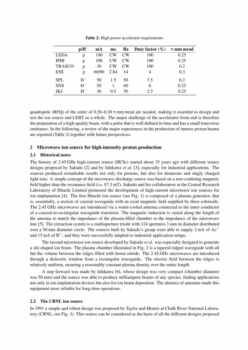
Table 2: High-power accelerator requirements.
p/H− mA ms Hz Duty factor (%) π mm mradLEDA p 100 CW CW 100 0.25IPHI p 100 CW CW 100 0.25TRASCO p 30 CW CW 100 0.2ESS p 60/90 2.84 14 4 0.3
SPL H− 50 1.5 50 7.5 0.2SNS H− 50 1 60 6 0.25JKJ H− 30 0.5 50 2.5 0.25
quadrupole (RFQ) of the order of 0.20–0.30 π mm mrad are needed, making it essential to design andtest the ion source and LEBT as a whole. The major challenge of the accelerator front-end is thereforethe preparation of a high-quality beam, with a pulse that is well defined in time and has a small transverseemittance. In the following, a review of the major experiences in the production of intense proton beamsare reported (Table 2) together with future perspectives.
2 Microwave ion source for high-intensity proton production2.1 Historical notesThe history of 2.45 GHz high-current source (HCSs) started about 35 years ago with different sourcedesigns proposed by Sakudo [2] and by Ishikawa et al. [3], especially for industrial applications. Thesources produced remarkable results not only for protons, but also for deuterons and singly chargedlight ions. A simple concept of the microwave discharge source was based on a non-confining magneticfield higher than the resonance field (i.e. 87.5 mT). Sakudo and his collaborators at the Central ResearchLaboratory of Hitachi Limited pioneered the development of high-current microwave ion sources forion implantation [4]. The first Hitachi ion source (see Fig. 1) is composed of a plasma generator, thatis, essentially, a section of coaxial waveguide with an axial magnetic field supplied by three solenoids.The 2.45 GHz microwaves are introduced via a water-cooled antenna connected to the inner conductorof a coaxial-to-rectangular waveguide transition. The magnetic induction is varied along the length ofthe antenna to match the impedance of the plasma-filled chamber to the impedance of the microwaveline [5]. The extraction system is a multiaperture triode with 124 apertures 3 mm in diameter distributedover a 50 mm diameter circle. The sources built by Sakudo’s group were able to supply 2 mA of As+
and 15 mA of B+, and they were successfully adapted to industrial application setups.
The second microwave ion source developed by Sakudo et al. was especially designed to generatea slit-shaped ion beam. The plasma chamber illustrated in Fig. 2 is a tapered ridged waveguide with allbut the volume between the ridges filled with boron nitride. The 2.45 GHz microwaves are introducedthrough a dielectric window from a rectangular waveguide. The electric field between the ridges isrelatively uniform, ensuring a reasonably constant plasma density over the entire length.
A step forward was made by Ishikawa [6], whose design was very compact (chamber diameterwas 50 mm) and the source was able to produce milliampere beams of any species, finding applicationsnot only in ion implantation devices but also for ion beam deposition. The absence of antennas made thisequipment more reliable for long-time operations.
2.2 The CRNL ion sourceIn 1991 a simple and robust design was proposed by Taylor and Mouris at Chalk River National Labora-tory (CRNL; see Fig. 3). This source can be considered as the basis of all the different designs proposed
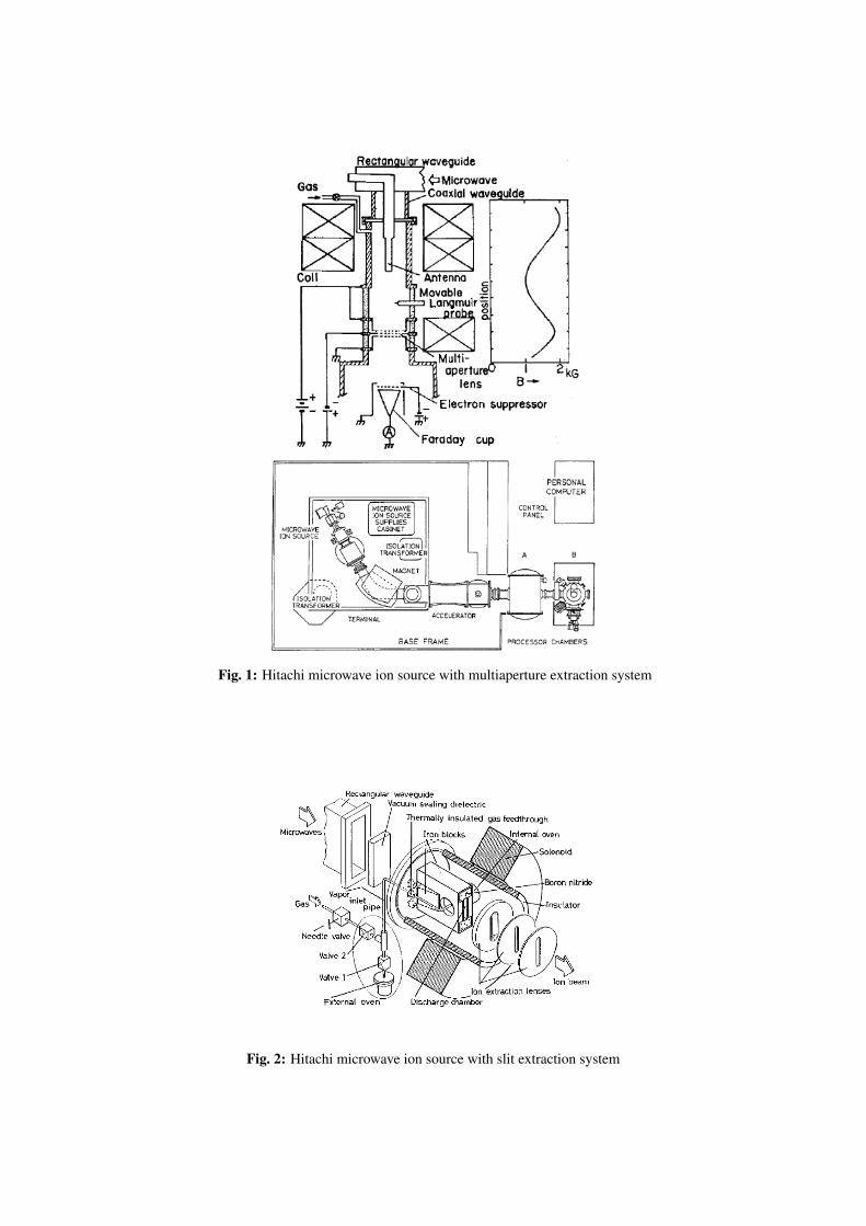
Fig. 1: Hitachi microwave ion source with multiaperture extraction system
Fig. 2: Hitachi microwave ion source with slit extraction system
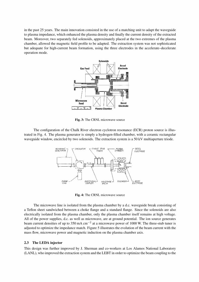
in the past 25 years. The main innovation consisted in the use of a matching unit to adapt the waveguideto plasma impedance, which enhanced the plasma density and finally the current density of the extractedbeam. Moreover, two separately fed solenoids, approximately placed at the two extremes of the plasmachamber, allowed the magnetic field profile to be adapted. The extraction system was not sophisticatedbut adequate for high-current beam formation, using the three electrodes in the accelerate–decelerateoperation mode.
Fig. 3: The CRNL microwave source
The configuration of the Chalk River electron cyclotron resonance (ECR) proton source is illus-trated in Fig. 4. The plasma generator is simply a hydrogen-filled chamber, with a ceramic rectangularwaveguide window, encircled by two solenoids. The extraction system is a 50 kV multiaperture triode.
Fig. 4: The CRNL microwave source
The microwave line is isolated from the plasma chamber by a d.c. waveguide break consisting ofa Teflon sheet sandwiched between a choke flange and a standard flange. Since the solenoids are alsoelectrically isolated from the plasma chamber, only the plasma chamber itself remains at high voltage.All of the power supplies, d.c. as well as microwave, are at ground potential. The ion source generatesbeam current densities of up to 350 mA cm−2 at a microwave power of 1000 W. The three-stub tuner isadjusted to optimize the impedance match. Figure 5 illustrates the evolution of the beam current with themass flow, microwave power and magnetic induction on the plasma chamber axis.
2.3 The LEDA injectorThis design was further improved by J. Sherman and co-workers at Los Alamos National Laboratory(LANL), who improved the extraction system and the LEBT in order to optimize the beam coupling to the
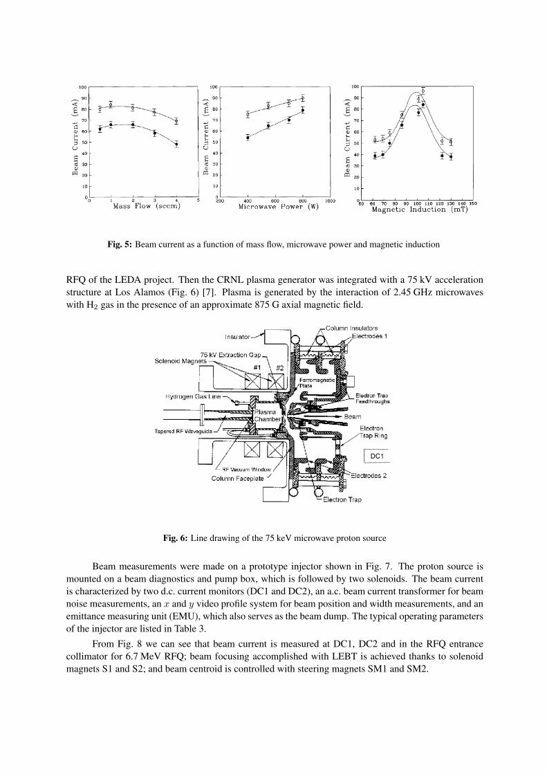
Fig. 5: Beam current as a function of mass flow, microwave power and magnetic induction
RFQ of the LEDA project. Then the CRNL plasma generator was integrated with a 75 kV accelerationstructure at Los Alamos (Fig. 6) [7]. Plasma is generated by the interaction of 2.45 GHz microwaveswith H2 gas in the presence of an approximate 875 G axial magnetic field.
Fig. 6: Line drawing of the 75 keV microwave proton source
Beam measurements were made on a prototype injector shown in Fig. 7. The proton source ismounted on a beam diagnostics and pump box, which is followed by two solenoids. The beam currentis characterized by two d.c. current monitors (DC1 and DC2), an a.c. beam current transformer for beamnoise measurements, an x and y video profile system for beam position and width measurements, and anemittance measuring unit (EMU), which also serves as the beam dump. The typical operating parametersof the injector are listed in Table 3.
From Fig. 8 we can see that beam current is measured at DC1, DC2 and in the RFQ entrancecollimator for 6.7 MeV RFQ; beam focusing accomplished with LEBT is achieved thanks to solenoidmagnets S1 and S2; and beam centroid is controlled with steering magnets SM1 and SM2.
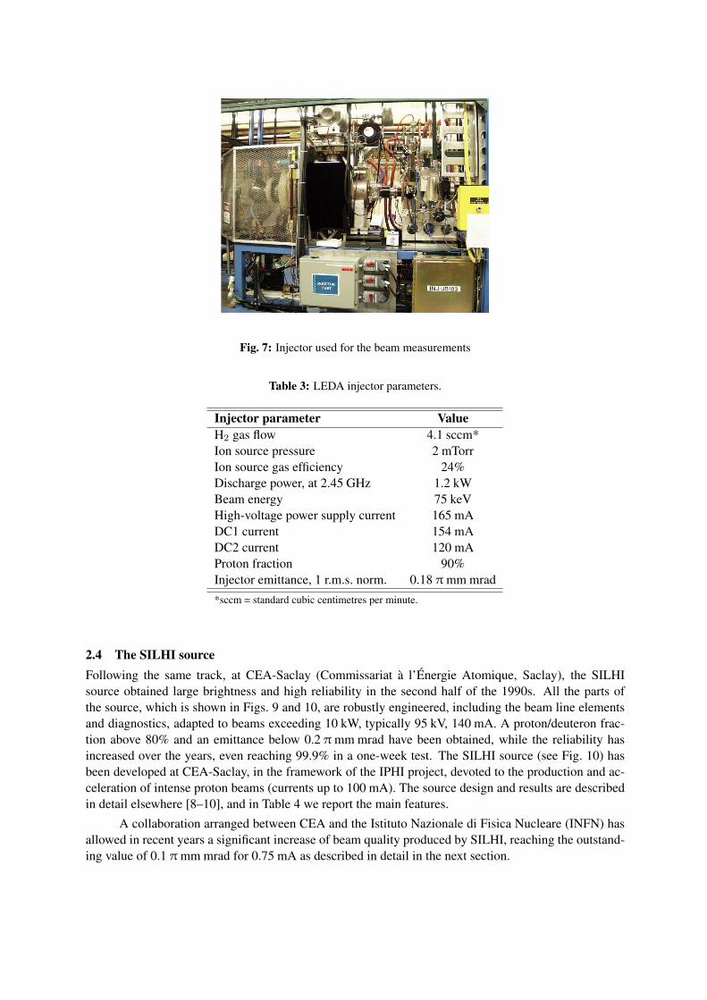
Fig. 7: Injector used for the beam measurements
Table 3: LEDA injector parameters.
Injector parameter ValueH2 gas flow 4.1 sccm*Ion source pressure 2 mTorrIon source gas efficiency 24%Discharge power, at 2.45 GHz 1.2 kWBeam energy 75 keVHigh-voltage power supply current 165 mADC1 current 154 mADC2 current 120 mAProton fraction 90%Injector emittance, 1 r.m.s. norm. 0.18 π mm mrad*sccm = standard cubic centimetres per minute.
2.4 The SILHI sourceFollowing the same track, at CEA-Saclay (Commissariat à l’Énergie Atomique, Saclay), the SILHIsource obtained large brightness and high reliability in the second half of the 1990s. All the parts ofthe source, which is shown in Figs. 9 and 10, are robustly engineered, including the beam line elementsand diagnostics, adapted to beams exceeding 10 kW, typically 95 kV, 140 mA. A proton/deuteron frac-tion above 80% and an emittance below 0.2 π mm mrad have been obtained, while the reliability hasincreased over the years, even reaching 99.9% in a one-week test. The SILHI source (see Fig. 10) hasbeen developed at CEA-Saclay, in the framework of the IPHI project, devoted to the production and ac-celeration of intense proton beams (currents up to 100 mA). The source design and results are describedin detail elsewhere [8–10], and in Table 4 we report the main features.
A collaboration arranged between CEA and the Istituto Nazionale di Fisica Nucleare (INFN) hasallowed in recent years a significant increase of beam quality produced by SILHI, reaching the outstand-ing value of 0.1 π mm mrad for 0.75 mA as described in detail in the next section.
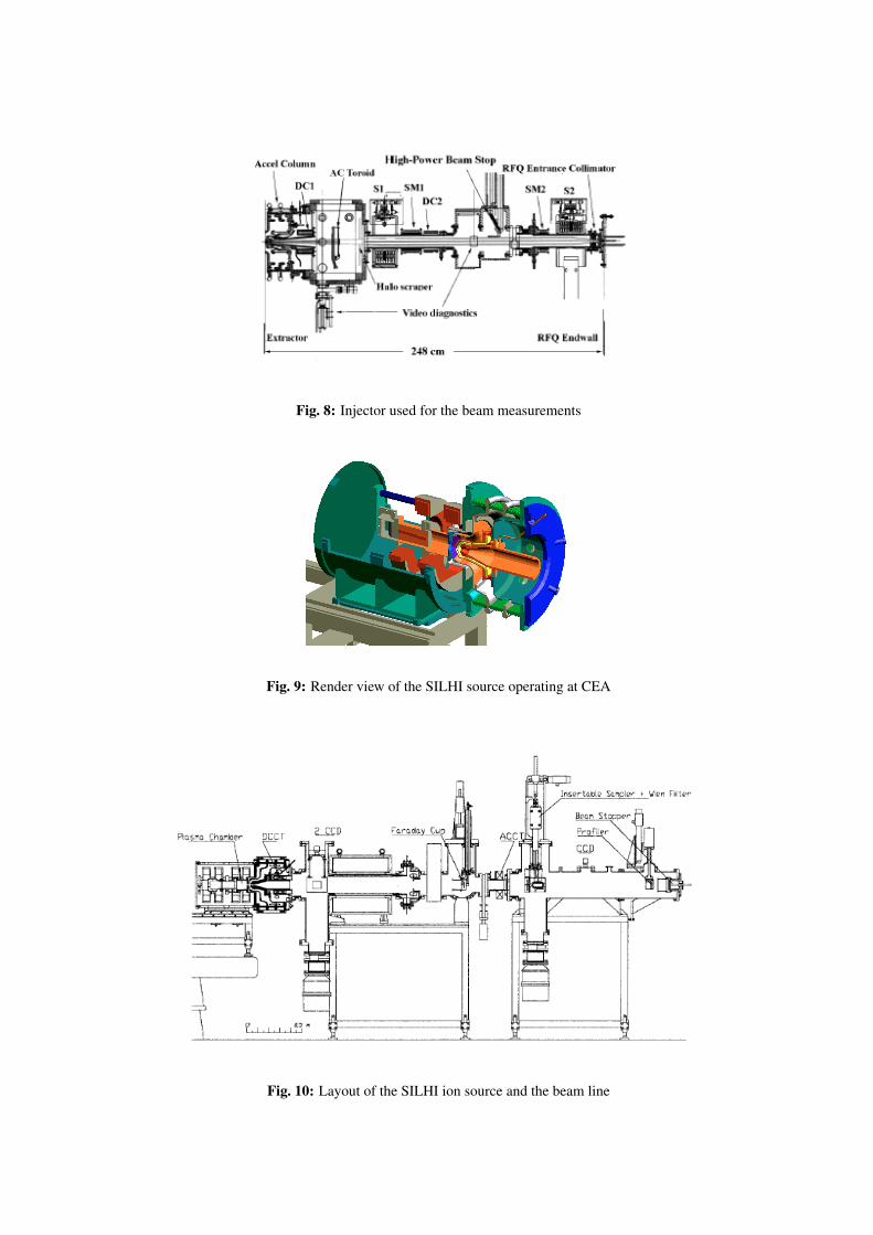
Fig. 8: Injector used for the beam measurements
Fig. 9: Render view of the SILHI source operating at CEA
Fig. 10: Layout of the SILHI ion source and the beam line
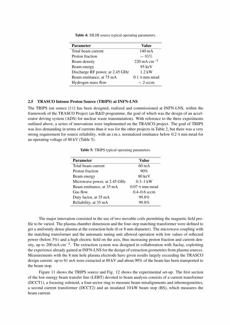
Table 4: SILHI source typical operating parameters.
Parameter ValueTotal beam current 140 mAProton fraction ∼ 85%Beam density 220 mA cm−2
Beam energy 95 keVDischarge RF power, at 2.45 GHz 1.2 kWBeam emittance, at 75 mA 0.1 π mm mradHydrogen mass flow ∼ 2 sccm
2.5 TRASCO Intense Proton Source (TRIPS) at INFN-LNSThe TRIPS ion source [11] has been designed, realized and commissioned at INFN-LNS, within theframework of the TRASCO Project (an R&D programme, the goal of which was the design of an accel-erator driving system (ADS) for nuclear waste transmutation). With reference to the three experimentsoutlined above, a series of innovations were implemented on the TRASCO project. The goal of TRIPSwas less demanding in terms of currents than it was for the other projects in Table 2, but there was a verystrong requirement for source reliability, with an r.m.s. normalized emittance below 0.2 π mm mrad foran operating voltage of 80 kV (Table 5).
Table 5: TRIPS typical operating parameters.
Parameter ValueTotal beam current 60 mAProton fraction 90%Beam energy 80 keVMicrowave power, at 2.45 GHz 0.3–1 kWBeam emittance, at 35 mA 0.07 π mm mradGas flow 0.4–0.6 sccmDuty factor, at 35 mA 99.8%Reliability, at 35 mA 99.8%
The major innovation consisted in the use of two movable coils permitting the magnetic field pro-file to be varied. The plasma chamber dimension and the four-step matching transformer were defined toget a uniformly dense plasma at the extraction hole (6 or 8 mm diameter). The microwave coupling withthe matching transformer and the automatic tuning unit allowed operation with low values of reflectedpower (below 5%) and a high electric field on the axis, thus increasing proton fraction and current den-sity, up to 200 mA cm−2. The extraction system was designed in collaboration with Saclay, exploitingthe experience already gained at INFN-LNS for the design of extraction geometries from plasma sources.Measurements with the 8 mm hole plasma electrode have given results largely exceeding the TRASCOdesign current: up to 61 mA were extracted at 80 kV and about 90% of the beam has been transported tothe beam stop.
Figure 11 shows the TRIPS source and Fig. 12 shows the experimental set-up. The first sectionof the low-energy beam transfer line (LEBT) devoted to beam analysis consists of a current transformer(DCCT1), a focusing solenoid, a four-sector ring to measure beam misalignments and inhomogeneities,a second current transformer (DCCT2) and an insulated 10 kW beam stop (BS), which measures thebeam current.
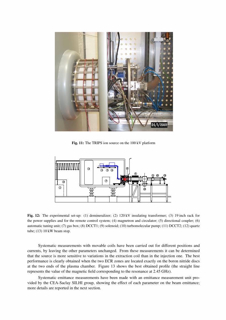
Fig. 11: The TRIPS ion source on the 100 kV platform
Fig. 12: The experimental set-up: (1) demineralizer; (2) 120 kV insulating transformer; (3) 19 inch rack forthe power supplies and for the remote control system; (4) magnetron and circulator; (5) directional coupler; (6)automatic tuning unit; (7) gas box; (8) DCCT1; (9) solenoid; (10) turbomolecular pump; (11) DCCT2; (12) quartztube; (13) 10 kW beam stop.
Systematic measurements with movable coils have been carried out for different positions andcurrents, by leaving the other parameters unchanged. From these measurements it can be determinedthat the source is more sensitive to variations in the extraction coil than in the injection one. The bestperformance is clearly obtained when the two ECR zones are located exactly on the boron nitride discsat the two ends of the plasma chamber. Figure 13 shows the best obtained profile (the straight linerepresents the value of the magnetic field corresponding to the resonance at 2.45 GHz).
Systematic emittance measurements have been made with an emittance measurement unit pro-vided by the CEA-Saclay SILHI group, showing the effect of each parameter on the beam emittance;more details are reported in the next section.
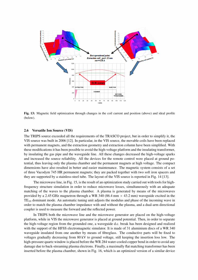
Fig. 13: Magnetic field optimization through changes in the coil current and position (above) and ideal profile(below).
2.6 Versatile Ion Source (VIS)The TRIPS source exceeded all the requirements of the TRASCO project, but in order to simplify it, theVIS source was built in 2006 [12]. In particular, in the VIS source, the movable coils have been replacedwith permanent magnets, and the extraction geometry and extraction column have been simplified. Withthese modifications it has been possible to avoid the high-voltage platform and the insulating transformer,by insulating the gas pipe and the waveguide line. All these changes decreased the high-voltage sparksand increased the source reliability. All the devices for the remote control were placed at ground po-tential, thus leaving only the plasma chamber and the permanent magnets at high voltage. The compactdimensions have also resulted in better and easier maintenance. The magnetic system consists of a setof three Vacodym 745 HR permanent magnets; they are packed together with two soft iron spacers andthey are supported by a stainless-steel tube. The layout of the VIS source is reported in Fig. 14 [13].
The microwave line, in Fig. 15, is the result of an optimization study carried out with tools for high-frequency structure simulation in order to reduce microwave losses, simultaneously with an adequatematching of the waves to the plasma chamber. A plasma is generated by means of the microwavesprovided by a 2.45 GHz magnetron through a WR 340 (86.4 mm × 43.2 mm) waveguide excited in theTE10 dominant mode. An automatic tuning unit adjusts the modulus and phase of the incoming wave inorder to match the plasma chamber impedance with and without the plasma, and a dual-arm directionalcoupler is used to measure the forward and the reflected power.
In TRIPS both the microwave line and the microwave generator are placed on the high-voltageplatform, while in VIS the microwave generator is placed at ground potential. Then, in order to separatethe high-voltage region from the grounded one, a waveguide d.c. break has been designed and realizedwith the support of the HFSS electromagnetic simulator. It is made of 31 aluminium discs of a WR 340waveguide insulated from one another by means of fibreglass. The conductive parts will be fixed tovoltages gradually decreasing from 80 kV to ground voltage, still keeping the insertion loss low. Thehigh-pressure quartz window is placed before the WR 284 water-cooled copper bend in order to avoid anydamage due to back-streaming plasma electrons. Finally, a maximally flat matching transformer has beeninserted before the plasma chamber, shown in Fig. 16, which is an optimized version of a similar device
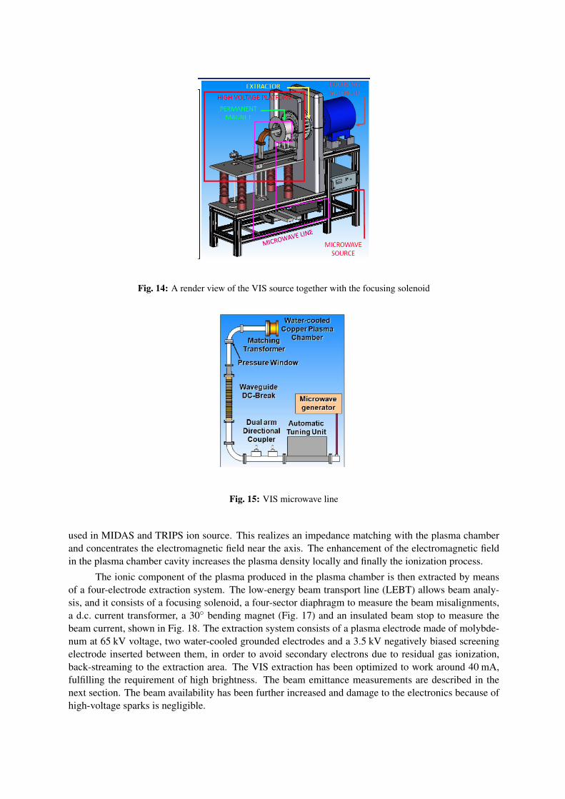
Fig. 14: A render view of the VIS source together with the focusing solenoid
Fig. 15: VIS microwave line
used in MIDAS and TRIPS ion source. This realizes an impedance matching with the plasma chamberand concentrates the electromagnetic field near the axis. The enhancement of the electromagnetic fieldin the plasma chamber cavity increases the plasma density locally and finally the ionization process.
The ionic component of the plasma produced in the plasma chamber is then extracted by meansof a four-electrode extraction system. The low-energy beam transport line (LEBT) allows beam analy-sis, and it consists of a focusing solenoid, a four-sector diaphragm to measure the beam misalignments,a d.c. current transformer, a 30◦ bending magnet (Fig. 17) and an insulated beam stop to measure thebeam current, shown in Fig. 18. The extraction system consists of a plasma electrode made of molybde-num at 65 kV voltage, two water-cooled grounded electrodes and a 3.5 kV negatively biased screeningelectrode inserted between them, in order to avoid secondary electrons due to residual gas ionization,back-streaming to the extraction area. The VIS extraction has been optimized to work around 40 mA,fulfilling the requirement of high brightness. The beam emittance measurements are described in thenext section. The beam availability has been further increased and damage to the electronics because ofhigh-voltage sparks is negligible.
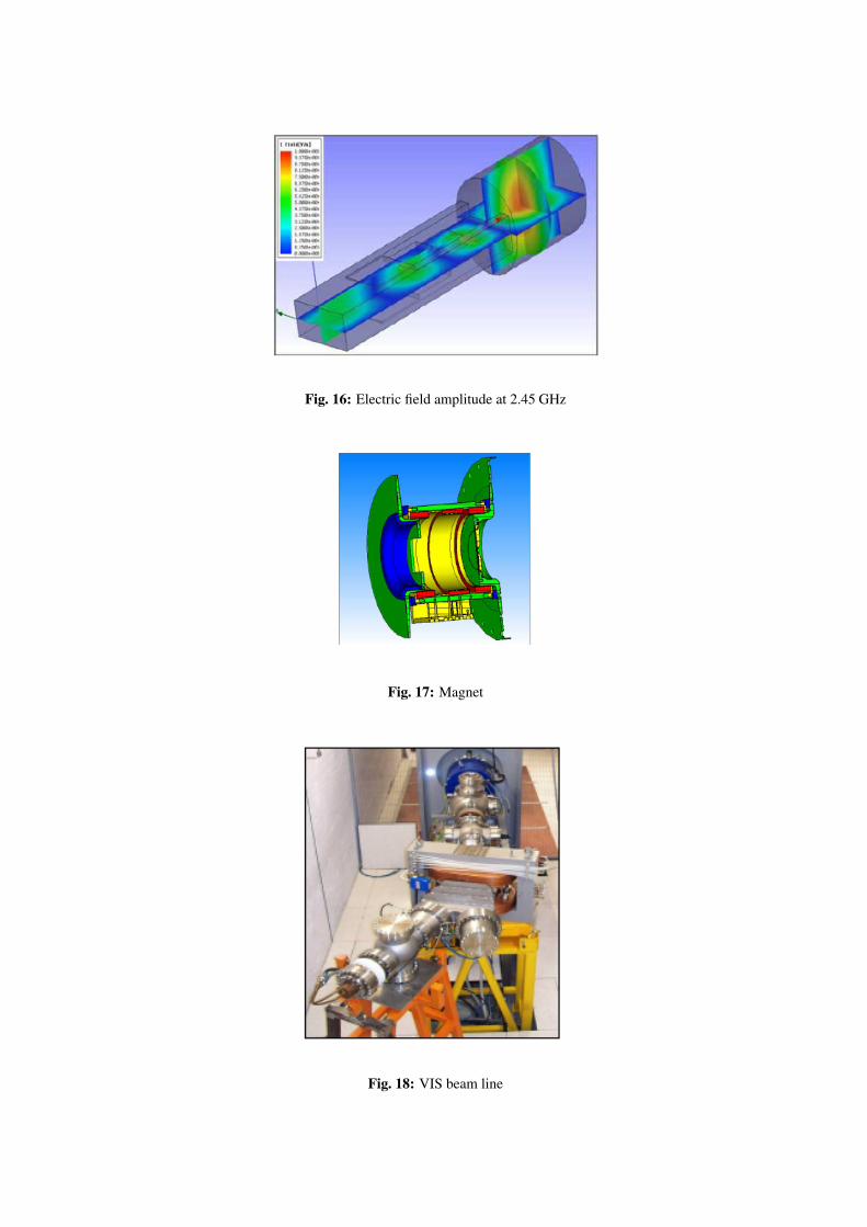
Fig. 16: Electric field amplitude at 2.45 GHz
Fig. 17: Magnet
Fig. 18: VIS beam line
3 Beam emittance measurementsThe production of a high-quality beam has been, since the first measurements made at CRNL by Taylorand Wills, one of the major challenges for such sources, together with beam reliability. Over the years,many developments have been carried out to improve these aspects, and the most important results havebeen obtained through a deep optimization of the extraction geometry together with an appropriate designof the low-energy beam transfer line.
3.1 SILHI beam emittance improvementsA significant step forward in this field, namely the production of a high-quality beam, was made withinthe framework of the collaboration between INFN and CEA, in which an innovative method based onthe controlled injection of a gas into the line was developed [14]. The idea is based on the fact thatthe ions obtained from residual gas ionization are expelled from the centre of the beam line, where thepotential is positive, towards the wall. Electrons from the wall are attracted towards the beam, so that thebeam is compensated, provided that the pressure is high enough to have an adequate number of electrons(a compromise between beam losses and space-charge compensation is to be found experimentally).According to that approach, the most effective gases are the heaviest, which easily release a large numberof electrons. If N hydrogen atoms per unit volume are required for optimum compensation (i.e. if Nelectrons neutralize the beam space charge), for a species that givesZeff electrons when the atoms interactwith the 95 keV proton beam, the optimum number of atoms per unit volume isN/Zeff (this clue neglectsthe dissociation process, which does not require a large amount of energy).
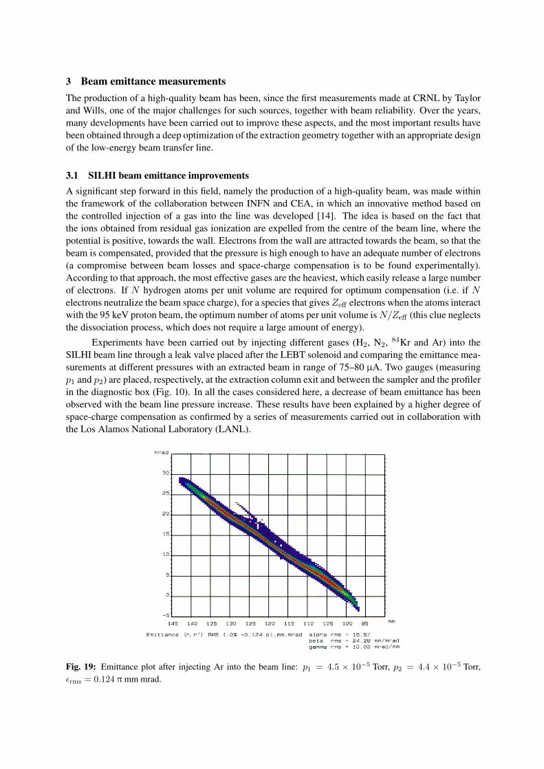
Experiments have been carried out by injecting different gases (H2, N2, 84Kr and Ar) into theSILHI beam line through a leak valve placed after the LEBT solenoid and comparing the emittance mea-surements at different pressures with an extracted beam in range of 75–80 µA. Two gauges (measuringp1 and p2) are placed, respectively, at the extraction column exit and between the sampler and the profilerin the diagnostic box (Fig. 10). In all the cases considered here, a decrease of beam emittance has beenobserved with the beam line pressure increase. These results have been explained by a higher degree ofspace-charge compensation as confirmed by a series of measurements carried out in collaboration withthe Los Alamos National Laboratory (LANL).
Fig. 19: Emittance plot after injecting Ar into the beam line: p1 = 4.5 × 10⁻⁵ Torr, p2 = 4.4 × 10⁻⁵ Torr,εrms = 0.124 π mm mrad.
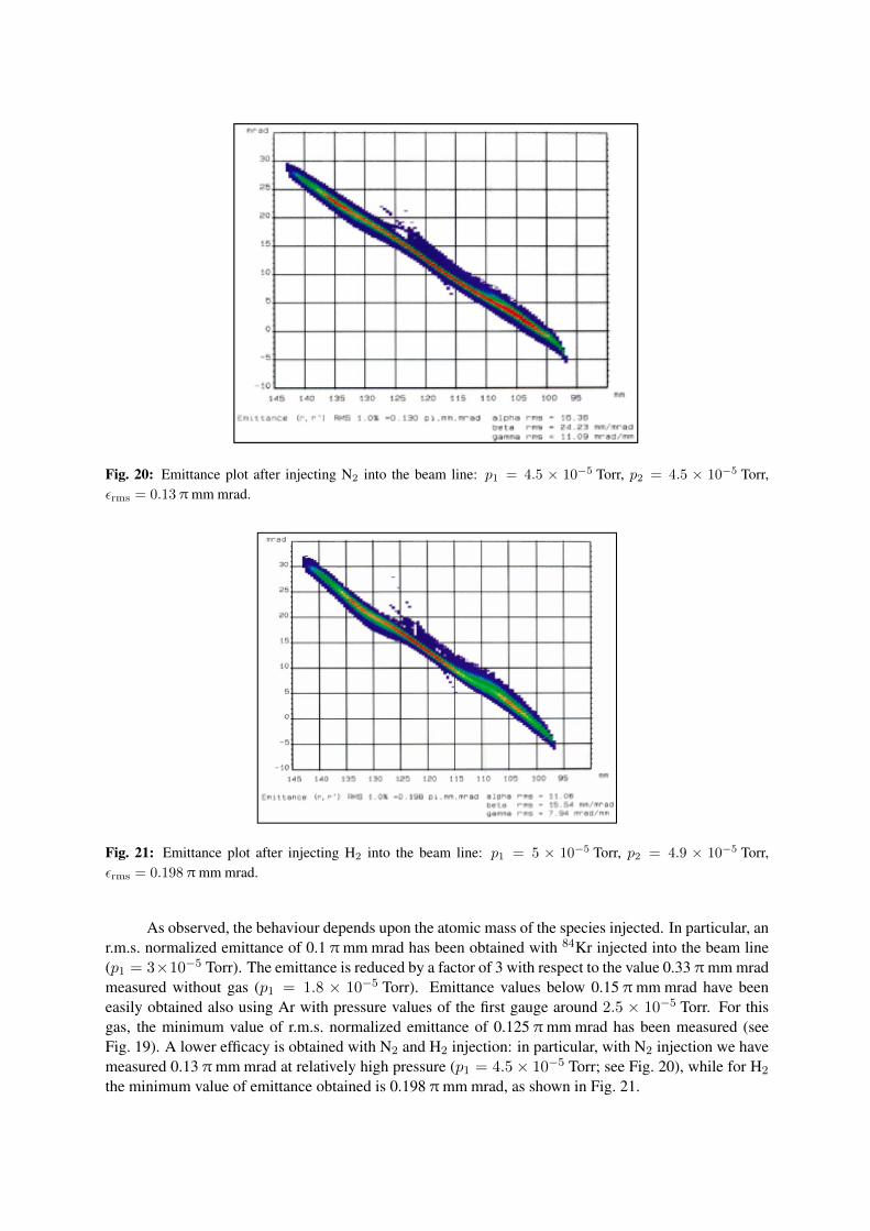
Fig. 20: Emittance plot after injecting N2 into the beam line: p1 = 4.5 × 10⁻⁵ Torr, p2 = 4.5 × 10⁻⁵ Torr,εrms = 0.13 π mm mrad.
Fig. 21: Emittance plot after injecting H2 into the beam line: p1 = 5 × 10⁻⁵ Torr, p2 = 4.9 × 10⁻⁵ Torr,εrms = 0.198 π mm mrad.
As observed, the behaviour depends upon the atomic mass of the species injected. In particular, anr.m.s. normalized emittance of 0.1 π mm mrad has been obtained with 84Kr injected into the beam line(p1 = 3×10⁻⁵ Torr). The emittance is reduced by a factor of 3 with respect to the value 0.33 π mm mradmeasured without gas (p1 = 1.8 × 10⁻⁵ Torr). Emittance values below 0.15 π mm mrad have beeneasily obtained also using Ar with pressure values of the first gauge around 2.5 × 10⁻⁵ Torr. For thisgas, the minimum value of r.m.s. normalized emittance of 0.125 π mm mrad has been measured (seeFig. 19). A lower efficacy is obtained with N2 and H2 injection: in particular, with N2 injection we havemeasured 0.13 π mm mrad at relatively high pressure (p1 = 4.5× 10⁻⁵ Torr; see Fig. 20), while for H2
the minimum value of emittance obtained is 0.198 π mm mrad, as shown in Fig. 21.
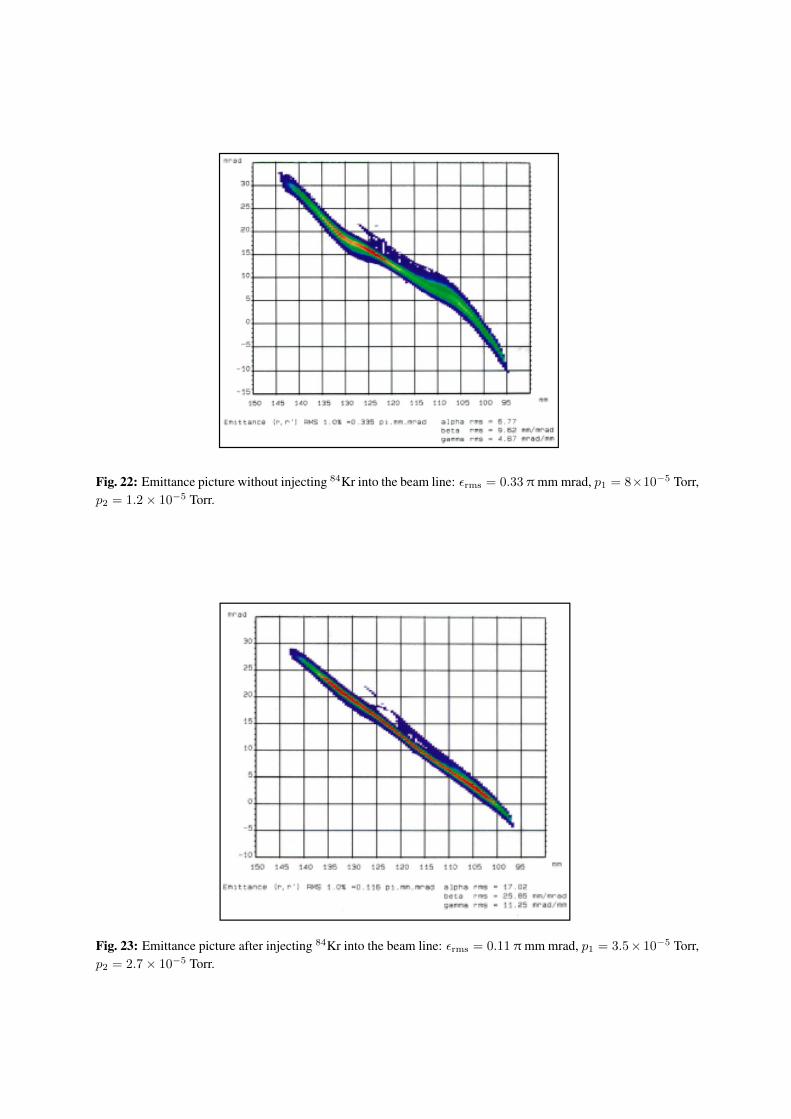
Fig. 22: Emittance picture without injecting 84Kr into the beam line: εrms = 0.33 π mm mrad, p1 = 8×10⁻⁵ Torr,p2 = 1.2× 10⁻⁵ Torr.
Fig. 23: Emittance picture after injecting 84Kr into the beam line: εrms = 0.11 π mm mrad, p1 = 3.5× 10⁻⁵ Torr,p2 = 2.7× 10⁻⁵ Torr.
Figures 22 and 23 show the emittance measurement obtained with 84Kr. It must be pointed out thatthe emittance pictures become straight with the gas injection and present a lower beam size and loweraberrations. This is also evident during the measurement because each beamlet selected by the samplerhas a lower width and a higher intensity.
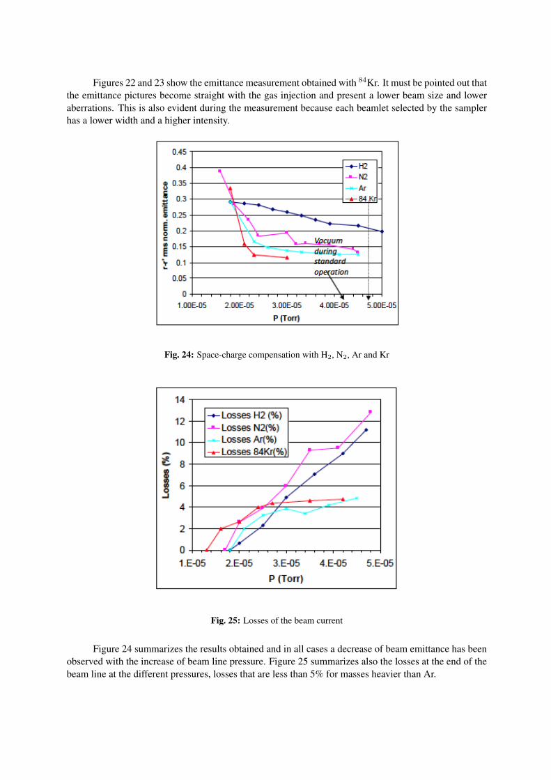
Fig. 24: Space-charge compensation with H2, N2, Ar and Kr
Fig. 25: Losses of the beam current
Figure 24 summarizes the results obtained and in all cases a decrease of beam emittance has beenobserved with the increase of beam line pressure. Figure 25 summarizes also the losses at the end of thebeam line at the different pressures, losses that are less than 5% for masses heavier than Ar.
3.2 TRIPS beam emittance improvementsThe requirement in terms of proton current for the TRIPS source (Table 2) was significantly lower thanthat for the SILHI source, and therefore (at the nominal beam current) gas injection has been not neces-sary to achieve the required goal. However, also in this case this method has been important to decreasethe emittance at higher currents.
In this case the measured values were coherent with the calculated ones and close to those pre-dicted by the equation
εnormal,rms =1
4× 0.0653r
(kT
A
)1/2
(πmmmrad), (1)
where r is the radius of the extraction aperture in millimetres, A is the rest mass of the ion in atomicunits and kT is the ion temperature in electronvolts. Assuming an ion temperature of 1 eV and with anextraction hole of 3 mm radius, the expected r.m.s. normalized emittance is circa 0.05 π mm mrad. Theemittance values measured are close to the theoretical one for a beam current close to the nominal value,while at higher currents the space-charge effects play an important role in the beam blowup, and a gasmust be added into the beam line to decrease the beam emittance.
Measurements [15] have been carried out at different current levels (between 30 and 50 mA); fora fixed current value, we have explored the effect of some parameters such as puller voltage and solenoidcurrent on the beam emittance. A first observation was that the emittance slightly changes with the pullervoltage for a fixed current. Measurements performed on a 42 mA beam, with the solenoid fixed at 290 A,a hydrogen flux of 0.49 sccm and a discharge power of 650 W, show a decrease of emittance from 0.208to 0.172 π mm mrad just by increasing the voltage drop between the extraction and puller electrode from38 to 43 kV. The optimal operating value ranges between 40 and 42 kV; unfortunately, for higher voltageHV discharges occur and it was not possible to operate the source safely. Another important observationwas obtained by looking at the evolution of the beam emittance by changing the solenoid strength forfixed source conditions.
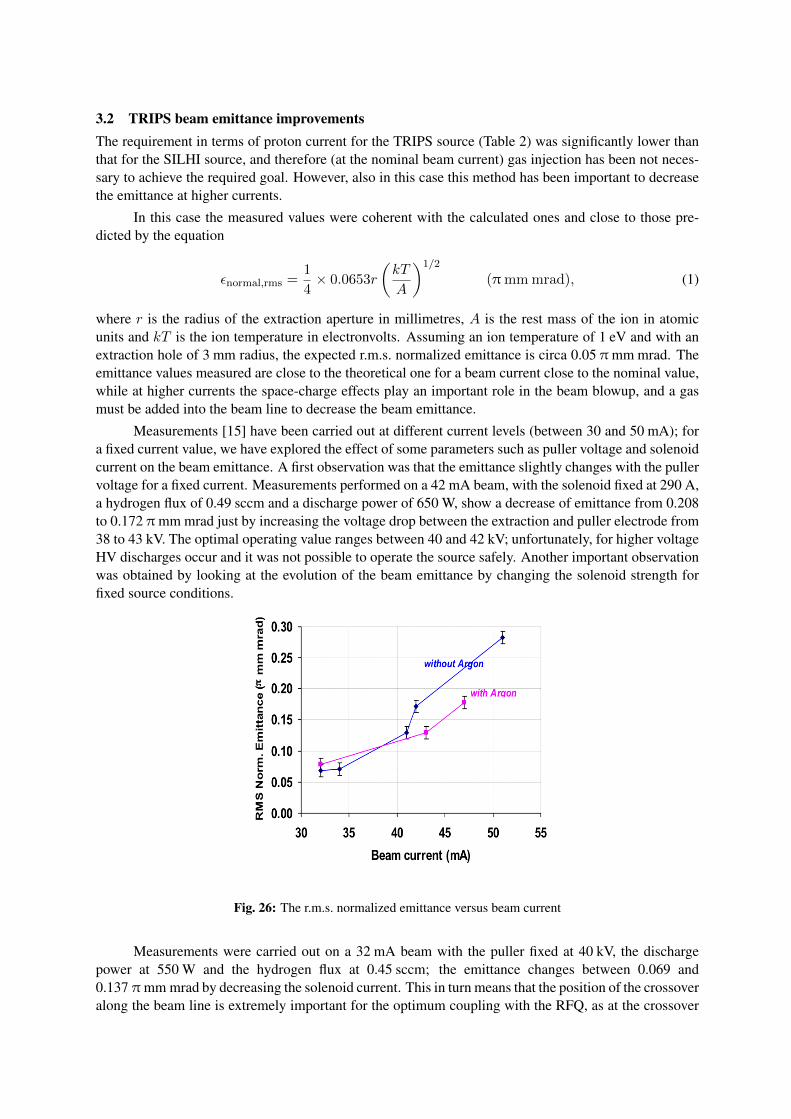
Fig. 26: The r.m.s. normalized emittance versus beam current
Measurements were carried out on a 32 mA beam with the puller fixed at 40 kV, the dischargepower at 550 W and the hydrogen flux at 0.45 sccm; the emittance changes between 0.069 and0.137 π mm mrad by decreasing the solenoid current. This in turn means that the position of the crossoveralong the beam line is extremely important for the optimum coupling with the RFQ, as at the crossover
the space-charge forces are more important, as confirmed by the measurements with a four-grid analyser.An optimal value of solenoid current for the operation with the EMU around 280 A has been found toavoid an excessive power density over the EMU sampler. Finally Fig. 26 shows the evolution of theemittance with the beam current increase; this confirms the influence of beam line pressure on the space-charge compensation (and thus on the emittance) by means of the injection of a controlled amount ofargon into the beam line, as already done for the SILHI source for different gases.
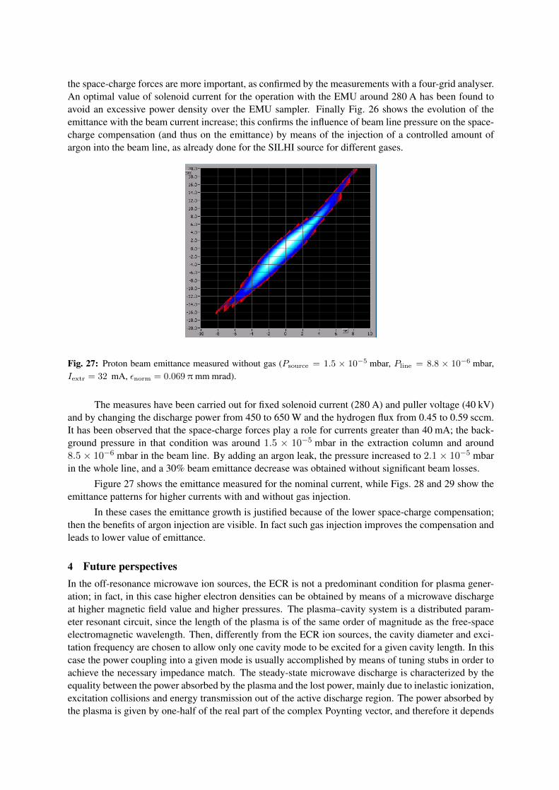
Fig. 27: Proton beam emittance measured without gas (Psource = 1.5 × 10⁻⁵ mbar, Pline = 8.8 × 10⁻⁶ mbar,Iextr = 32 mA, εnorm = 0.069 π mm mrad).
The measures have been carried out for fixed solenoid current (280 A) and puller voltage (40 kV)and by changing the discharge power from 450 to 650 W and the hydrogen flux from 0.45 to 0.59 sccm.It has been observed that the space-charge forces play a role for currents greater than 40 mA; the back-ground pressure in that condition was around 1.5 × 10⁻⁵ mbar in the extraction column and around8.5 × 10−6 mbar in the beam line. By adding an argon leak, the pressure increased to 2.1 × 10⁻⁵ mbarin the whole line, and a 30% beam emittance decrease was obtained without significant beam losses.
Figure 27 shows the emittance measured for the nominal current, while Figs. 28 and 29 show theemittance patterns for higher currents with and without gas injection.
In these cases the emittance growth is justified because of the lower space-charge compensation;then the benefits of argon injection are visible. In fact such gas injection improves the compensation andleads to lower value of emittance.
4 Future perspectivesIn the off-resonance microwave ion sources, the ECR is not a predominant condition for plasma gener-ation; in fact, in this case higher electron densities can be obtained by means of a microwave dischargeat higher magnetic field value and higher pressures. The plasma–cavity system is a distributed param-eter resonant circuit, since the length of the plasma is of the same order of magnitude as the free-spaceelectromagnetic wavelength. Then, differently from the ECR ion sources, the cavity diameter and exci-tation frequency are chosen to allow only one cavity mode to be excited for a given cavity length. In thiscase the power coupling into a given mode is usually accomplished by means of tuning stubs in order toachieve the necessary impedance match. The steady-state microwave discharge is characterized by theequality between the power absorbed by the plasma and the lost power, mainly due to inelastic ionization,excitation collisions and energy transmission out of the active discharge region. The power absorbed bythe plasma is given by one-half of the real part of the complex Poynting vector, and therefore it depends
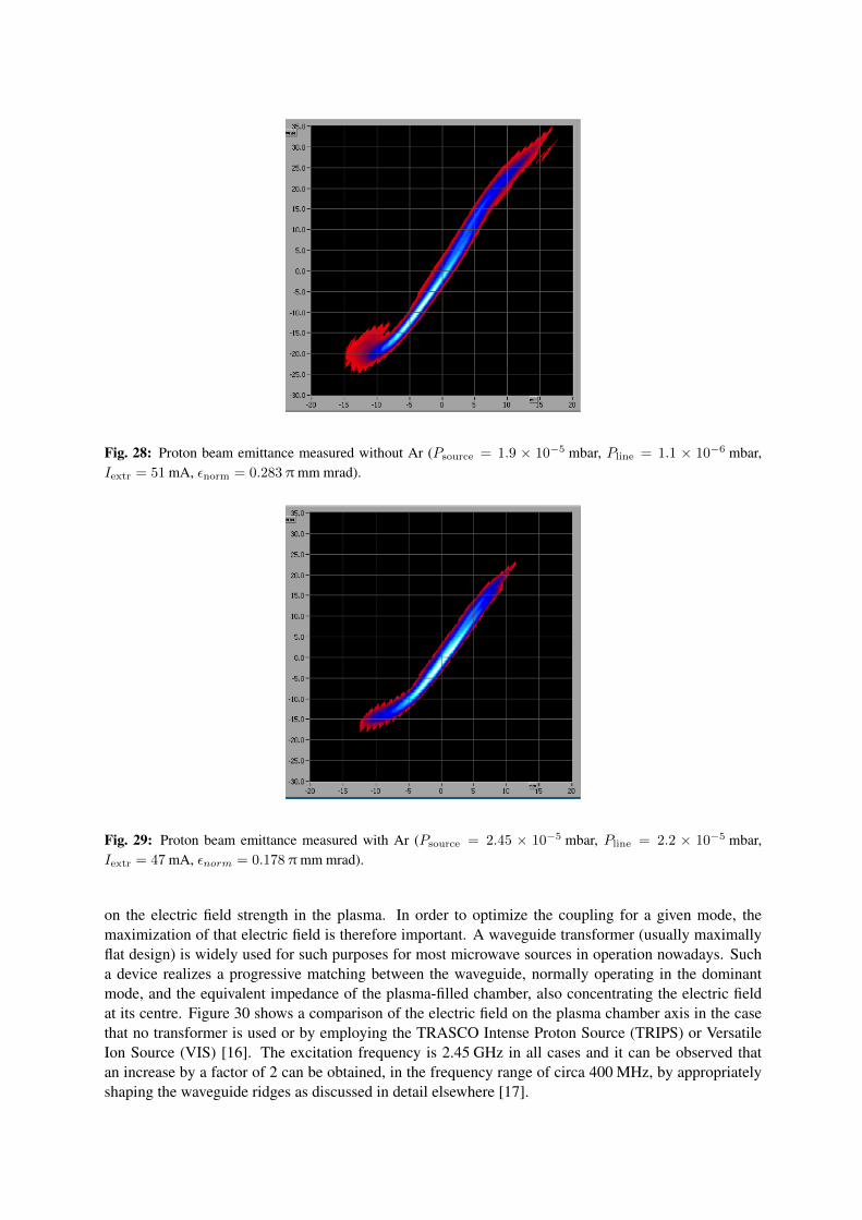
Fig. 28: Proton beam emittance measured without Ar (Psource = 1.9 × 10⁻⁵ mbar, Pline = 1.1 × 10⁻⁶ mbar,Iextr = 51 mA, εnorm = 0.283 π mm mrad).
Fig. 29: Proton beam emittance measured with Ar (Psource = 2.45 × 10⁻⁵ mbar, Pline = 2.2 × 10⁻⁵ mbar,Iextr = 47 mA, εnorm = 0.178 π mm mrad).
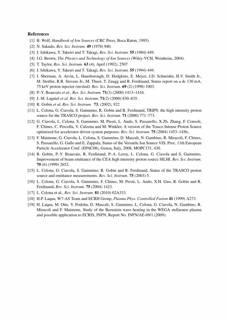
on the electric field strength in the plasma. In order to optimize the coupling for a given mode, themaximization of that electric field is therefore important. A waveguide transformer (usually maximallyflat design) is widely used for such purposes for most microwave sources in operation nowadays. Sucha device realizes a progressive matching between the waveguide, normally operating in the dominantmode, and the equivalent impedance of the plasma-filled chamber, also concentrating the electric fieldat its centre. Figure 30 shows a comparison of the electric field on the plasma chamber axis in the casethat no transformer is used or by employing the TRASCO Intense Proton Source (TRIPS) or VersatileIon Source (VIS) [16]. The excitation frequency is 2.45 GHz in all cases and it can be observed thatan increase by a factor of 2 can be obtained, in the frequency range of circa 400 MHz, by appropriatelyshaping the waveguide ridges as discussed in detail elsewhere [17].
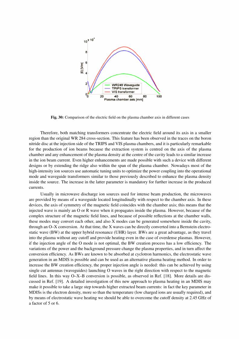
Fig. 30: Comparison of the electric field on the plasma chamber axis in different cases
Therefore, both matching transformers concentrate the electric field around its axis in a smallerregion than the original WR 284 cross-section. This feature has been observed in the traces on the boronnitride disc at the injection side of the TRIPS and VIS plasma chambers, and it is particularly remarkablefor the production of ion beams because the extraction system is centred on the axis of the plasmachamber and any enhancement of the plasma density at the centre of the cavity leads to a similar increasein the ion beam current. Even higher enhancements are made possible with such a device with differentdesigns or by extending the ridge also within the span of the plasma chamber. Nowadays most of thehigh-intensity ion sources use automatic tuning units to optimize the power coupling into the operationalmode and waveguide transformers similar to those previously described to enhance the plasma densityinside the source. The increase in the latter parameter is mandatory for further increase in the producedcurrents.
Usually in microwave discharge ion sources used for intense beam production, the microwavesare provided by means of a waveguide located longitudinally with respect to the chamber axis. In thesedevices, the axis of symmetry of the magnetic field coincides with the chamber axis; this means that theinjected wave is mainly an O or R wave when it propagates inside the plasma. However, because of thecomplex structure of the magnetic field lines, and because of possible reflections at the chamber walls,these modes may convert each other, and also X modes can be generated somewhere inside the cavity,through an O–X conversion. At that time, the X waves can be directly converted into a Bernstein electro-static wave (BW) at the upper hybrid resonance (UHR) layer. BWs are a great advantage, as they travelinto the plasma without any cutoff and provide heating even in the case of overdense plasmas. However,if the injection angle of the O mode is not optimal, the BW creation process has a low efficiency. Thevariations of the power and the background pressure change the plasma properties, and in turn affect theconversion efficiency. As BWs are known to be absorbed at cyclotron harmonics, the electrostatic wavegeneration in an MDIS is possible and can be used as an alternative plasma heating method. In order toincrease the BW creation efficiency, the proper injection angle is needed: this can be achieved by usingsingle cut antennas (waveguides) launching O waves in the right direction with respect to the magneticfield lines. In this way O–X–B conversion is possible, as observed in Ref. [18]. More details are dis-cussed in Ref. [19]. A detailed investigation of this new approach to plasma heating in an MDIS maymake it possible to take a large step towards higher extracted beam currents: in fact the key parameter inMDISs is the electron density, more so than the temperature (low charged ions are usually required), andby means of electrostatic wave heating we should be able to overcome the cutoff density at 2.45 GHz ofa factor of 5 or 6.
References[1] B. Wolf, Handbook of Ion Sources (CRC Press, Boca Raton, 1995).[2] N. Sakudo, Rev. Sci. Instrum. 49 (1978) 940.[3] J. Ishikawa, Y. Takeiri and T. Takagi, Rev. Sci. Instrum. 55 (1984) 449.[4] I.G. Brown, The Physics and Technology of Ion Sources (Wiley-VCH, Weinheim, 2004).[5] T. Taylor, Rev. Sci. Instrum. 63 (4), April (1992), 2507[6] J. Ishikawa, Y. Takeiri and T. Takagi, Rev. Sci. Instrum. 55 (1994) 449.[7] J. Sherman, A. Arvin, L. Hansborough, D. Hodgkins, E. Meyer, J.D. Schneider, H.V. Smith Jr.,
M. Stettler, R.R. Stevens Jr., M. Thuot, T. Zaugg and R. Ferdinand, Status report on a dc 130 mA,75 keV proton injector (invited). Rev. Sci. Instrum. 69 (2) (1998) 1003.
[8] P.-Y. Beauvais et al., Rev. Sci. Instrum. 71(3) (2000) 1413–1416.[9] J.-M. Lagniel et al. Rev. Sci. Instrum. 71(2) (2000) 830–835.
[10] R. Gobin et al. Rev. Sci. Instrum. 73, (2002), 922[11] L. Celona, G. Ciavola, S. Gammino, R. Gobin and R. Ferdinand, TRIPS: the high intensity proton
source for the TRASCO project. Rev. Sci. Instrum. 71 (2000) 771–773.[12] G. Ciavola, L. Celona, S. Gammino, M. Presti, L. Ando, S. Passarello, X.Zh. Zhang, F. Consoli,
F. Chines, C. Percolla, V. Calzona and M. Winkler, A version of the Trasco Intense Proton Sourceoptimized for accelerator driven system purposes. Rev. Sci. Instrum. 75 (2004) 1453–1456,.
[13] F. Maimone, G. Ciavola, L. Celona, S. Gammino, D. Mascali, N. Gambino, R. Miracoli, F. Chines,S. Passarello, G. Gallo and E. Zappala, Status of the Versatile Ion Source VIS, Proc. 11th EuropeanParticle Accelerator Conf. (EPAC08), Genoa, Italy, 2008, MOPC151, 430.
[14] R. Gobin, P.-Y. Beauvais, R. Ferdinand, P.-A. Leroy, L. Celona, G. Ciavola and S. Gammino,Improvement of beam emittance of the CEA high intensity proton source SILHI. Rev. Sci. Instrum.70 (6) (1999) 2652.
[15] L. Celona, G. Ciavola, S. Gammino, R. Gobin and R. Ferdinand, Status of the TRASCO protonsource and emittance measurements. Rev. Sci. Instrum. 75 (2003) 5.
[16] L. Celona, G. Ciavola, S. Gammino, F. Chines, M. Presti, L. Ando, X.H. Guo, R. Gobin and R.Ferdinand, Rev. Sci. Instrum. 75 (2004) 1423.
[17] L. Celona et al., Rev. Sci. Instrum. 81 (2010) 02A333.[18] H.P. Laqua, W7-AS Team and ECRH Group, Plasma Phys. Controlled Fusion 41 (1999) A273.[19] H. Laqua, M. Otte, Y. Podoba, D. Mascali, S. Gammino, L. Celona, G. Ciavola, N. Gambino, R.
Miracoli and F. Maimone, Study of the Bernstein wave heating in the WEGA stellarator plasmaand possible application to ECRIS, INFN, Report No. INFN/AE-09/1 (2009).