microstrip rf surface coil design for extremely high-field mri and spectroscopy
TRANSCRIPT

Microstrip RF Surface Coil Design for ExtremelyHigh-Field MRI and Spectroscopy
Xiaoliang Zhang, Kamil Ugurbil, and Wei Chen*
A new type of high-frequency RF surface coil was developed forin vivo proton or other nuclei NMR applications at 7T. This is apurely distributed-element and transmission line design. Thecoil consists of a thin strip conductor (copper or silver) and aground plane separated by a low-loss dielectric material with athickness (H). Due to its specific semi-open transmission linestructure, substantial electromagnetic energy is stored in thedielectric material between the thin conductor and the groundplane, which results in a reduced radiation loss and a reducedperturbation of sample loading to the RF coil compared toconventional surface coils. The coil is characterized by a high Qfactor, no RF shielding, small physical coil size, lower cost, andeasy fabrication. A brief theoretical description of the micros-trip RF coil is given that can be used to guide the coil designs.A set of gradient-recalled echo images were acquired by usingthe single- and two-turn microstrip RF surface coils from bothphantom and human brain at 7T, which show good penetrationand sensitivity. The two-turn coil design significantly improvesthe B1 symmetry as predicted by the microstrip theory. Theoptimum H for microstrip surface coils is approximately 7 mm.This coil geometry yields a B1 penetration similar to that ofconventional surface coils. SNR comparison was made be-tween the microstrip coil and conventional surface coils withand without RF shielding. The results reveal that the novelsurface coil design based on the microstrip concept makes veryhigh-field MRI/MRS more convenient and efficient in researchand future clinics. Magn Reson Med 46:443–450, 2001.© 2001 Wiley-Liss, Inc.
Key words: 7 Tesla; microstrip resonator; RF coil; surface coil;high field; MR imaging; brain
In vivo MR studies at very high magnetic fields (.3T) arefundamentally advantageous due to their characteristics ofinherent high SNR, and thus possible high spatial andspectral resolution (1–3). RF coils are a critically importantfactor for a high-field MRI scanner for realizing such highsensitivity. With the advent of very high magnetic field MRscanners, ranging from 3–8T for human applications, aneed for efficient high-frequency RF coils has emerged. Itis well known that radiation losses and the interactionbetween coil and subject increase with the increase ofresonance frequency. The problems become significantlymore pronounced at 300 MHz, the proton Larmor fre-quency at 7T as considered in this work. These effectsresult in reduced coil Q factor and diminished sensitivityof MR images. RF shielding methods based on TEM prin-
ciples appear to be the only existing solutions to preventloss from RF radiation at high magnetic fields (4–9). In thisarticle we introduce a new design for high-frequency sur-face coils based on the microstrip transmission line con-cept, which is simple and avoids the use of lumped ele-ments as employed with discrete capacitors. Unlike con-ventional RF shielded surface coils, there is no need tohave an RF shield for the microstrip surface coil. There-fore, it can be built considerably more compact and hencesaves valuable space inside the extremely high-field mag-nets. The microstrip surface coil is a completely distrib-uted element design and can be easily operated up to500 MHz when a low loss and appropriate permittivitydielectric material is used for the desired coil diameters.Our experimental results indicate that the concept of themicrostrip RF coil has the capability to develop a variety oftraditional surface coils at high frequencies without RFshielding, such as quadrature surface coils, butterfly coils,Helmholtz pairs, and phased array surface coils. Further-more, the same concept can be used to design linear and/orquadrature volume coils for the human head and bodyimaging at high magnetic fields.
THEORY
Quasistatic Solution
The simplest unit of the microstrip transmission line(10,11) consists of a thin strip conductor and a groundplane separated by a low-loss dielectric material. The anal-ysis model of microstrip line was based on an approximatequasistatic assumption. Also, the fields have sinusoidaltime dependence. In order to simplify the problem, it isnecessary to place conductive sidewalls (ground) on eachside, as shown in Fig. 1. Notice that most of the field linesare around the strip conductor on the microstrip line. Inthis case, width l .. thickness H, which ensures that boththe field (electric and magnetic) lines near the strip con-ductor are not perturbed by the sidewalls. Therefore, theboundary conditions under this assumption should be:
F~x, y! 5 0, at x 5 6l2
and/or y 5 0, ` [1]
where F(x,y) is a scalar potential and satisfies Laplace’sequation:
¹2F~x, y! 5 0, for uxu #l2
and 0 # y , `. [2]
The method of variable separation can be employed tosolve Laplace’s equation, Eq. [2], under the boundary con-ditions as described by Eq. [1]. The general solutions are:
Center for Magnetic Resonance Research, Departments of Radiology, Uni-versity of Minnesota School of Medicine, Minneapolis, Minnesota.Grant sponsor: NIH; Grant numbers: NS38070; NS39043; P41 RR08079 (aNational Research Resource grant); Grant sponsors: Keck Foundation; Na-tional Foundation for Functional Brain Imaging; US Department of Energy.*Correspondence to: Wei Chen, Ph.D., Center for Magnetic Resonance Re-search, Department of Radiology, University of Minnesota School of Medi-cine, 2021 6th Street S.E., Minneapolis, MN 55455. E-mail:[email protected] 6 October 2000; revised 10 May 2001; accepted 1 June 2001.
Magnetic Resonance in Medicine 46:443–450 (2001)
© 2001 Wiley-Liss, Inc. 443

F~x, y! 5 Ok51,odd
`
Akcoskpx
lsinh
kpyl
, for 0 # y # H [3]
and:
F~x, y! 5 Ok51,odd
`
Bkcoskpx
lexpS2kpy
l D,
for H # y , ` [4]
where Ak and Bk are coefficients to be determined and theyare not independent of each other. Notice that at point y 5H, the potential F(x,y) must be continuous. Therefore, therelationship between Ak and Bk can be found by equatingEq. [3] to Eq. [4] when y 5 H:
Bk 5 AksinhSkpHl DexpSkpH
l D for y 5 H. [5]
Thus, the potential F(x,y) for H # y , ` can be furtherexpressed in terms of Ak:
F~x, y! 5 Ok51,odd
`
AkcosSkpxl DsinhSkpH
l DexpSkpH 2 kpyl D
for H # y , `. [6]
Considering E field in y direction, Ey 5 2]F( x,y)/] y, andthen evaluating the surface charge density (r) on the stripat y 5 H1, H2:
r 5 ε0Eyuy5H1 2 ε0εrEyuy5H2 [7]
where ε0, εr are the permittivity or the relative dielectricconstants of free space (approximately air) and dielectricmaterial used, respectively. In the microstrip line case,obviously the charge density on the strip is 1, while out-
side the strip the charge density is zero if we approximatethat the charge density is uniformly distributed. It is worthnoticing that in the real case the charge distribution is notuniform, but weaker in the center and stronger on theedges of the strip (12,13). However, this approximation ofthe uniform distribution of charge is accurate enoughwhen we consider the far fields, which is the case in MRstudies. Thus, the coefficient Ak can be found as:
Ak 54l sin~kpW/2l!
ε0k2p2$εr z cosh~kpH/l! 1 sinh~kpH/l!%. [8]
Therefore, Eqs. [3], [6], and [8] give the general solution toestimate the scalar potential, consequently, electric field(EY 5 2¹F z ejvt) and magnetic field (i.e. 21/jv¹3EY z ejvt) of the microstrip line under the assumedboundary conditions.
Microstrip Transmission Line Resonator
From the above solution, some basic parameters of themicrostrip resonator, such as characteristic impedance,propagation constant, wavelength, physical length, andother parameters of the coil for a certain resonant fre-quency can be derived.
Due to its semi-open structure, where the electromag-netic field lines are partly in substrate and partly in air, themicrostrip line does not support pure transverse electro-magnetic modes (TEM modes) but quasi-TEM modes forthe frequency range that is of interest in MR imagingstudies. In terms of the dielectric constant, a modifiedvalue, i.e., a so-called effective dielectric constant εeff hasto be employed instead of the relative dielectric constantof the substrate. For microstrip coils described in thisarticle, the relationship between the strip conductor thick-ness t and the dielectric material thickness H, t/H #0.005holds. Therefore, the strip thickness t of the microstrip coilcan be considered as zero or small enough to be negligiblein practical situations (14). The following derivations arebased on this assumption. In fact, the primary effect of thestrip conductor with thickness t is to increase the capaci-tance per unit length of the microstrip line. Thus, if thisassumption cannot be satisfied, i.e., the strip thickness thas to be considered, the correction can be approximatelymade by replacing the strip width W by the effective widthWeff, which is slightly larger than the physical width W. Tosimplify the analysis, all of the following derivations willnot take into account fringing fields and the effects ofcorner and curvature of the microstrip resonator.
The resonance wavelength of the microstrip resonator isgiven by:
l 5l0
Îεeff
[9]
where l0 is the wavelength of light in free space. Under thelossless assumption, the propagation constant can be ex-pressed as:
b 5 k0Îεeff [10]
FIG. 1. A sketch of microstrip transmission line. To simplify thecalculation, two ground sidewalls were added on each side. Its fielddistribution implies potential applications to high field magneticresonance studies. W is the width of the strip conductor, H is thethickness of the dielectric material or substrate and l is the width ofthe ground plane.
444 Zhang et al.

where k0 5 vÎm0ε0 (m0 is the permeability of free spaceand v is resonant angular frequency) is the wave numberof free space.
The relative dielectric constant of the substrate εr, thedielectric substrate thickness H, and the width of the stripconductor W determine the characteristic impedance ofthe microstrip resonator. The relations for characteristicimpedance are given by (14):
Z0 560
Îεeff
lnS8HW
1W4HDuW/H#1
, [11]
where:
εeff 5εr 1 1
21
εr 2 1
2Î1 112HW
1 0.02~εr 2 1!S1 2WHD2
[12]
otherwise:
Z0 5120p
Îεeff HWH
1 1.393 1 0.667 lnSWH
1 1.444DJuW/H$1
,
[13]
where:
εeff 5εr 1 1
21
εr 2 1
2Î1 112HW
. [14]
It is worth noticing that at the wide conductor limit theeffective permittivity εeff becomes substrate’s permittivityεr, that is:
limW..H
εeff 5 εr. [15]
There is a fundamental (or primary) resonance and itshigher-order harmonics operating in the microstrip reso-
FIG. 2. Single-turn microstrip surface coil with the square shape.
Microstrip RF Surface Coil at 7T 445
nator. The primary resonance is usually desirable for NMRexperiments and it occurs when the physical length L (i.e.,the perimeter of the coil loop) of the resonator is about halfthe wavelength of the primary resonance, i.e., L 5 l/ 2.Therefore, the fundamental resonant frequency is calcu-lated as:
f 5c
2LÎεeff
[16]
where c is the speed of light in free space.
MATERIALS AND METHODS
Single- and two-turn microstrip surface coils with differ-ent dimensions were designed and built for proton MRimaging at 7T, corresponding to the resonant frequency of297.3 MHz. The basic structure of the microstrip coil in thesquare shape is depicted in Fig. 2. All the substrates (di-electric material) used were PTFE, which has a low losstangent (tand , 0.0003) and a permittivity of 2.1. Otherkinds of low-loss dielectric materials with different per-mittivity can certainly be used for different frequency anddifferent coil dimension designs. The sizes of the coils in
the square shape were 9 3 9 cm2. Because corners of thecoil tend to radiate surface waves and thus have a potentialto cause hot spots in images and degrade the Q value ofcoils, the corners had been chamfered to reduce the radi-ation loss and improve B1 distribution. Five coils withvarious values of substrate thickness H (0.8, 3, 5, 7, and13.5 mm) were built for studying B1 penetration and signalintensity distribution. Another two-turn microstrip coil inthe square shape was built. The coil size was 5 3 5 cm2
measured in the middle between the inner and outerloops. The strip conductors and ground planes of micros-trip coils were made from 36-mm thick adhesive-bakedcopper tape (3M, St. Paul, MN). The width W of the stripconductor for all coils was 7 mm. All the coils described inthis article were built with open-circuited microstrip linesof 0.5l length related to the primary resonant frequency. Atrimmer capacitor (Voltronics, Denville, NJ) connected inseries served as the matching network to couple the coil.The coil was connected via an RF adapter, which convertsthe microstrip to coaxial line, to the T/R switch of NMRscanner. Frequency tuning (fine tuning) can be conducted
Table 1Comparison of Substrate Thickness H and B1 Penetration.
Size of coils(cm)
Substrate thickness H(mm)
B1 penetration(cm)
9 3 9 0.8 5.49 3 9 3 7.09 3 9 5 8.59 3 9 7 8.59 3 9 13.5 8.410 in diameter* / 9
*10-cm regular circular surface coil with RF shielding.The measurements were taken with 9 3 9 cm2 square shape single-turn coil operating at 297.3 MHz. Due to less dielectric resonanceconstant and low loss, a mineral oil phantom was used to mimic theB1 property in the unloaded case.
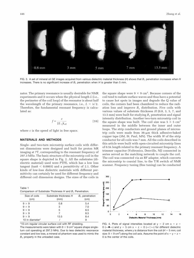
FIG. 3. A set of mineral oil GE images acquired from various dielectric material thickness (H) shows that B1 penetration increases when Hincreases. There is no significant increase of B1 penetration when H is greater than 5 mm.
FIG. 4. Plots of signal intensities located at y 5 2 cm x 5 z 50 (—}—) and y 5 5 cm x 5 z 5 0 (—E—) for different dielectricmaterial thickness, where y is distance from the coil (H 5 5 mm; coilsize: 9 3 9 cm2) along the coil axis. Assume the point of x 5 y 5 z 50 is the center of the coils.
446 Zhang et al.
by slightly changing the length of the strip conductor. Foreach coil the primary resonant frequency was confirmedusing the scattering parameter, namely, the reflection co-efficient S11 and/or the transmission coefficient S21 (witha shielded 1.5-cm single loop sniffer) measurements takenon a Hewlett Packard Model 4396A network analyzer witha frequency range of 100 KHz to 1.8 GHz. The transmissioncoefficient S21 measurement was also used to measure thecoil’s Q values for both unloaded and loaded (with thehuman head) cases with two shielded 1.5-cm single loopsniffers. The penetration measurements for each coil werebased on the depth that the MR signal intensity decayed to5% of the maximum signal intensity.
MR imaging experiments with these coils were per-formed on a 7T/90cm magnet (Magnex, UK) interfaced tothe Varian INOVA console (Varian Associates, Palo Alto,CA). To realistically map the B1 field of this new coildesign, a mineral oil phantom (a cylindrical bottle with a15-cm diameter and a 24-cm length) which has a relativelylow permittivity of about 2.8 and, hence, a minimizeddielectric resonance effect at 7T, was used. Images wereacquired to demonstrate the B1 distribution for both single-and two-turn coils. In addition, sets of human head imageswere acquired from the same system setup. The gradient-recalled echo (GE) images were used to acquire MR im-ages. Other MRI parameters were: 3.5 ms TE, 500 ms TR,128 3 128 matrix size, 24 3 24 cm field of view, and 5 mmslice thickness.
Finally, three coils, microstrip coil, conventional sur-face coil, and shielded surface coil, were built to compareSNR. All three coils were in a round shape and had thesame diameter of 11 cm. The thickness of the substrate Hof the microstrip coil was 7 mm and the width W of the
strip was 7 mm. The conventional surface coils were madefrom 7 mm wide copper strip, the same as that of micros-trip coil. The distance between the coil and RF shieldingwas 4.5 cm for the best SNR, according to the reports ofRefs. 5 and 6. Since subject position relative to coil isextremely sensitive to the results of SNR measurement, aholder was built to ensure that the subject could be placedin the exact same position in all experiments. The distancebetween coils and the study subject along the coil axis inall studies was 11 mm. A 15-cm diameter by 24-cm longbottle fully filled with mineral oil was used as an imagingsubject. A GE imaging sequence was utilized in acquiringall images for SNR comparisons. A long TR of 8.4 sec,which is about three times T1 at 7T, was applied in allimages to minimize the possible saturation effect. Otherrelated imaging parameters were TE 5 3.4 ms, matrixsize 5 128 3 128, FOV 5 20 3 20cm. Most importantly,we kept all parameters the same in all the experiments.Transverse images were collected at the center of each coil.A small box (6 3 6 pixels) was selected to measure theSNR along the coil axis step-by-step continuously.
RESULTS AND DISCUSSION
The prototype microstrip RF surface coils, which have atuning range of ;30 MHz, were built to operate at297.3 MHz for proton imaging at 7T. Figure 2 illustratesthe single-turn microstrip RF coil design in the squareshape (Figs. 2a,b). The measured resonate frequencieswere compared with the calculated results based on themethod as described in the Theory section. The agreementwas within 3%. The Q values of the single-turn square-shaped microstrip coil (H 5 5 mm; coil size: 9 3 9 cm2)were 306 for unloaded case and 90 for loaded case with thehuman head. A greater ratio of W/H provides a higherunloaded Q value. As a comparison, the unloaded andloaded Q values of a conventional 11-cm diameter surfacecoil with eight split capacitors were measured (95.3 vs.28.5 at 7T). The higher unloaded as well as loaded Qvalues of the microstrip surface coil indicate that the mi-crostrip RF surface coil has a significant reduction of ra-diation loss at 7T. The ratio of unloaded Q to loaded Q was3.4. Nonetheless, this ratio can be further improved byoptimizing the ratio W/H and/or the permittivity of thesubstrate of coils.
To evaluate the B1 field of the coils in the unloaded case,a set of gradient echo (GE) proton images of a mineral oilphantom, which approximates the B1 pattern of the un-loaded coils, was acquired with a nominal 90° flip angle,which was obtained when a global maximum signal wasreached. Figure 3 and Table 1 show the qualitative rela-tionship between the penetration of B1 or MRI signal in-tensity and the thickness H of dielectric material used. Theresults indicate that the penetration is approximately pro-portional to H when H is less than 5 mm. When H in-creases to more than 5 mm, the B1 penetration in themineral oil was approximately constant. The degree of theB1 penetration is in agreement with the penetration rela-tionship for the conventional circular surface coil (10-cmdiameter) where the same crossed coil area (;80 cm2) wasused and the penetration was approximately equal to the
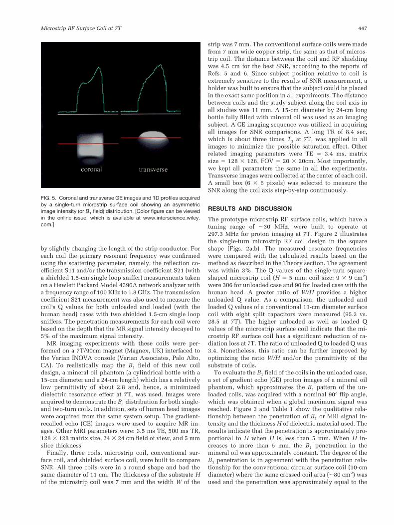
FIG. 5. Coronal and transverse GE images and 1D profiles acquiredby a single-turn microstrip surface coil showing an asymmetricimage intensity (or B1 field) distribution. [Color figure can be viewedin the online issue, which is available at www.interscience.wiley.com.]
Microstrip RF Surface Coil at 7T 447

FIG. 6. Two-turn microstrip surface coil with the square shape (a) and its cross section (b).
FIG. 7. Coronal and transverse GE imagesand 1D profiles acquired by a two-turn mi-crostrip surface coil showing a symmetricimage intensity (or B1 field) distribution.[Color figure can be viewed in the online issue,which is available at www.interscience.wiley.com.]
448 Zhang et al.

diameter of the surface coil (Table 1). Figure 4 shows therelationship between the signal intensity and thickness Hof dielectric material from the central pixels located at2 cm and 5 cm from the surface coil plane, respectively.The signal intensity has a similar relationship as a func-tion of the substrate thickness H in comparison to the B1
penetration, i.e., the MRI signal intensity is proportional toH when H , 5 mm and reaches a maximum when H $5 mm. These results indicate that the optimized H value isabout 5–7 mm for the microstrip RF surface coil size asdescribed in this article.
From the images acquired with the single-turn coils andtheir one-dimensional profiles as shown in Fig. 5, thecoil’s B1 is not symmetric due to the nature of the currentdistribution of the open-circuited microstrip resonator(weak current on both ends of the microstrip coil and
strong current in the middle of coil). One of the ap-proaches to obtain a relatively symmetric B1 from themicrostrip coil design is the use of the two-turn microstripcoil design (Fig. 6a,b for the square shape coil design),where the inhomogeneous current density in the innerloop is compensated by the current density in the outerloop. A symmetric image acquired from the mineral oilphantom with the two-turn coil (Fig. 7) shows the effi-ciency of this approach for achieving a symmetric B1 field.
The result of the SNR comparison was shown in Fig. 8.Microstrip surface coil and shielded surface coil have acomparable SNR at 297.3 MHz, while the regular surfacecoil without RF shielding has an approximate 20% SNRloss compared to that of the microstrip coil within therange of ;8 cm from the coil plane.
Figure 9 illustrates the GE images in three orientationsfrom a healthy volunteer obtained with the 9 3 9 cm2
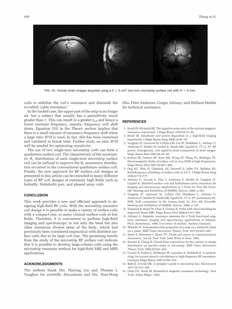
single-turn microstrip coil (H 5 5 mm2). Figure 10 illus-trates the similar GE images from another healthy volun-teer obtained with the 5 3 5 cm2 two-turn microstrip coil(H 5 5 mm). In these images, a 2-ms Gaussian pulse witha low power (6.4 W) was used to achieve a nominal 90° flipangle. Good MRI quality was obtained for both of themicrostrip coils.
The dielectric material thickness H, or more accurately,the ratio W/H, is an important parameter that affects the B1
penetration in air. If H is too small, or W/H too large, mostof electromagnetic fields will be compressed around thestrip conductor. Although the B1 penetration will increasewith the increase of dielectric material thickness H, or thedecrease of the ratio W/H, a thickness of 5–7 mm is sug-gested in practice because the radiation loss can becomesignificant when the substrate is much thicker. This opti-mized H makes it possible to build a very thin surface coilat extremely high fields, where the coil thickness can beonly 1/6 – 1/8 of the conventional surface coil with RFshielding. Due to the unbalanced circuit of the microstripcoil, there is no need to use a balun circuit that is com-monly used in most of surface coils and balanced volume
FIG. 8. Measured SNRs from three transverse GE images along thecoil axis acquired from a mineral oil phantom using microstripsurface coil (F), regular surface coil (h), and shielded surface coil(‚). The coil planes were located at 21.1 cm along the coil axis asindicated by the arrow.
FIG. 9. Human brain images acquired using a 9 3 9 cm2 single-turn microstrip surface coil with H 5 5 mm. The dark areas appearing inthe coronal (right insert) and transverse (left insert) images were caused by dielectric effects at 7T in the human brain.
Microstrip RF Surface Coil at 7T 449
coils to stabilize the coil’s resonance and diminish theso-called ‘cable resonance.’
In the loaded case, the upper part of the strip is no longerair, but a subject that usually has a permittivity muchgreater than 1. This can result in a greater εeff and hence alower resonant frequency, namely, frequency will shiftdown. Equation [15] in the Theory section implies thatthere is a small amount of resonance frequency shift whena large ratio W/H is used. In fact, this has been examinedand validated in bench tests. Further study on ratio W/Hwill be needed for optimizing sensitivity.
The use of two single-turn microstrip coils can form aquadrature surface coil. The characteristic of the asymmet-ric B1 distribution of each single-turn microstrip surfacecoil can be utilized to improve the B1 asymmetry distribu-tion occurred in the conventional quadrature surface coil.Finally, the new approach for RF surface coil designs aspresented in this article can be extended to many differenttypes of RF coil designs at extremely high fields such asbutterfly, Helmholtz pair, and phased array coils.
CONCLUSION
This work provides a new and efficient approach to de-signing high-field RF coils. With the microstrip resonatorcoil design it is possible to make a variety of surface coilswith a compact size, as many clinical surface coils at lowfields. Therefore, it is convenient to perform high-fieldimaging and spectroscopy in not only the head but alsoother numerous diverse areas of the body, which hadpreviously been considered impractical with shielded sur-face coils due to its large coil size. The promising resultsfrom the study of the microstrip RF surface coil indicatethat it is possible to develop large-volume coils using themicrostrip resonator method for high-field MRI and MRSapplications.
ACKNOWLEDGMENTS
The authors thank Drs. Haiying Liu and Thomas J.Vaughan for scientific discussions and Drs. Xiao-Hong
Zhu, Peter Andersen, Gregor Adriany, and Hellmut Merklefor technical assistance.
REFERENCES
1. Hoult DI, Richards RE. The signal-to-noise ratio of the nuclear magneticresonance experiment. J Magn Reson 1976;24:71–85.
2. Hoult DI. Sensitivity and power deposition in a high-field imagingexperiment. J Magn Reson Imag 2000;12:46–67.
3. Vaughan JT, Garwood M, Collins CM, Liu W, DelaBarre L, Adriany G,Andersen P, Merkle H, Goebel R, Smith MB, Ugurbil K. 7T vs. 4T: RFpower, homogeneity, and signal-to-noise comparison in head images.Magn Reson Med 2001;46:24–30.
4. Keltner JR, Carlson JW, Roos MS, Wong ST, Wong TL, Budinger TF.Electromagnetic fields of surface coil in vivo NMR at high frequencies.Magn Reson Med 1991;22:467–480.
5. Ong KC, Wen H, Chesnick AS, Duewell S, Jaffer FA, Balaban RS.Radiofrequency shielding of surface coils at 4.0 T. J Magn Reson Imag1995;5:773–777.
6. Adriany G, Yacoub E, Tkac I, Andersen P, Merkle H, Vaughan JT,Ugurbil K. Shielded surface coil and halfvolume cavity resonators forimaging and spectroscopy applications at 7 Tesla. In: Proc 8th Scien-tific Meeting and Exhibition of ISMRM, Denver, 2000. p 563.
7. Vaughan JT, Garwood M, Collins CM, DelaBarre L, Adriany G,Andersen P, Merkle H, Smith MB, Ugurbil K. 7T vs. 4T: preliminary B1,SNR, SAR comparison in the human head. In: Proc 8th ScientificMeeting and Exhibition of ISMRM, Denver, 2000. p 147.
8. Tomanek B, Hoult DI, Chen X, Gordon R. Probe with chest shielding forimproved breast MRI. Magn Reson Med 2000;43:917–920.
9. Adriany G. Magnetic resonance antennas for 4 Tesla functional mag-netic resonance imaging and spectroscopy applications in humans.Ph.D. dissertation, 1998, University of Aachen: Aachen, Germany.
10. Wheeler H. Transmission-line properties of a strip on a dielectric sheeton a plane. IEEE Trans Microwave Theory Tech 1977;25:631–647.
11. Ramo S, Whinnery J, Duzer TV. Fields and waves in communicationselectronics, 3rd ed. New York: John Wiley & Sons; 1994.
12. Kuester E, Chang D. Closed-form expressions for the current or chargedistribution on parallel strips or microstrip. IEEE Trans MicrowaveTheory Tech 1980;28:254–259.
13. Crozier S, Forbes L, Roffmann W, Luescher K, Doddrell D. A method-ology for current density calculations in high-frequency RF resonators.Concepts Magn Reson 1997;9:195–210.
14. Bahl IJ, Trivedi DK. A designer’s guide to microstrip line. Microwaves1977;16:174–182.
15. Chen CN, Hoult DI, Biomedical magnetic resonance technology. NewYork: Adam Hilger; 1989.
FIG. 10. Human brain images acquired using a 5 3 5 cm2 two-turn microstrip surface coil with H 5 5 mm.
450 Zhang et al.