micro-hydraulic toolkit report
TRANSCRIPT

Defence Research and Recherche et développement Development Canada pour la défense Canada
Micro-Hydraulic Toolkit Report
Defence R&D Canada
Contract Report
DRDC Suffield CR 2008-212
December 2006
Guillaume Lambert, Collineo inc. Contract Scientific Authority: B. Beckman, DRDC Suffield
The scientific or technical validity of this Contract Report is entirely the responsibility of the contractor and the contents do not necessarily have the approval or endorsement of Defence R&D Canada.


Micro-Hydraulic Toolkit Report
Guillaume Lambert Collineo inc. 1375 rue Gay-Lussac, bureau A Boucherville QC J4B 7K1 Contract Number: W7702-03R975 Contract Scientific Authority: B. Beckman (403-544-5502) The scientific or technical validity of this Contract Report is entirely the responsibility of the contractor and the contents do not necessarily have the approval or endorsement of Defence R&D Canada.
DRDC Suffield CR 2008-212 December 2006
Defence R&D Canada – Suffield Contract Report

© Collineo inc., 2008

MICRO-HYDRAULIC TOOLKIT
USER MANUAL
V1.0
December 2006

Table of contents
1 - INTRODUCTION.................................................................................................................. 5
2 - TOOLKIT ARCHITECTURE AND SUBSYSTEMS DESCRIPTION.................................... 62.1 - Generic functional breakdown of any machine...........................................................................62.2 - Functional breakdown of the toolkit............................................................................................ 7
2.2.1 - Main functional breakdown tree.......................................................................................... 72.2.2 - Subsidiary functional breakdown trees............................................................................... 8
2.3 - Toolkit's physical subsystems...................................................................................................112.3.1 - Wheel drive module.......................................................................................................... 122.3.2 - Direction articulation module.............................................................................................142.3.3 - Intramotion articulation module......................................................................................... 182.3.4 - Traction variation module..................................................................................................202.3.5 - Intramotion variation module.............................................................................................232.3.6 - Propulsion hydraulic power supply module.......................................................................262.3.7 - Intramotion hydraulic power supply module......................................................................292.3.8 - Electric power accumulation module.................................................................................322.3.9 - Electronic power supply module....................................................................................... 332.3.10 - Electric power supply regulation module........................................................................ 362.3.11 - Electronic and processing module (prototype)................................................................39
3 - ASSEMBLY AND POSSIBLE KIT CONFIGURATIONS................................................... 453.1 - Individual connections...............................................................................................................45
3.1.1 - Mechanical connection standard.......................................................................................453.1.2 - Hydraulic connection standard..........................................................................................47
3.2 - Assembly techniques and hints................................................................................................ 483.3 - Assembly examples.................................................................................................................. 49
3.3.1 - Leg type 1 assembly (straight locomotion – no direction module)....................................493.3.2 - Leg type 2 assembly (with direction module)....................................................................533.3.3 - Complete toolkit assembly................................................................................................ 573.3.4 - Top surface component layout (Suggested)....................................................................60
3.4 - Known toolkit assemblies......................................................................................................... 613.4.1 - Assembly # 1 – 4 rigid wheels vehicle.............................................................................. 613.4.2 - Assembly # 2 – 4 wheels, 2 direction, 4 2-DOF legs articulated vehicle.......................... 623.4.3 - Other possible configurations........................................................................................... 63
3.5 - Operation capability examples..................................................................................................64
1458 RUE MICHAUD, DRUMMONDVILLE, QC, CANADA, J2C [email protected] 819-479-0624
2
High mobility roboticsPrototypes and mechatronic systems manufacturing
Industrial and technical services

4 - SUBSYSTEM CONFIGURATION AND OPERATION INTERFACE................................. 654.1 - Communication......................................................................................................................... 654.2 - CAN and CANopen general information...................................................................................664.3 - Subsystem configuration.......................................................................................................... 68
4.3.1 - Hydraulic valve.................................................................................................................. 684.3.2 - Electric motor controller.................................................................................................... 714.3.3 - PID compensation.............................................................................................................734.3.4 - Processing node............................................................................................................... 744.3.5 - Using CANopen Magic Pro to configure subsystems....................................................... 74
4.4 - Operation interface................................................................................................................... 754.4.1 - Operation mode................................................................................................................ 754.4.2 - Process data..................................................................................................................... 764.4.3 - Using CANopen Magic Pro to operate the Toolkit............................................................ 76
5 - SUBSYSTEMS REGULATION.......................................................................................... 785.1 - Wheel drive module.................................................................................................................. 795.2 - Direction articulation module.................................................................................................... 805.3 - Intramotion articulation module.................................................................................................815.4 - Propulsion hydraulic power supply module.............................................................................. 825.5 - Intramotion hydraulic power supply module............................................................................. 83
6 - SAFETY CONSIDERATIONS............................................................................................ 846.1 - Handling....................................................................................................................................846.2 - Heavy objects fall......................................................................................................................846.3 - Subsystems in operation.......................................................................................................... 85
6.3.1 - Electrical shock................................................................................................................. 856.3.2 - Hydraulic pressure leakage cuts.......................................................................................856.3.3 - Burns due to motor heat................................................................................................... 85
6.4 - Vehicle in motion.......................................................................................................................866.4.1 - Body part cut..................................................................................................................... 866.4.2 - Security area..................................................................................................................... 876.4.3 - External power supply limitations (portable recharge system)......................................... 876.4.4 - Toolkit's legs stepping on operator's foot..........................................................................87
7 - BASIC REPAIR AND MAINTENANCE.............................................................................. 887.1 - Periodical maintenance............................................................................................................ 88
7.1.1 - Mechanical systems.......................................................................................................... 887.1.2 - Hydraulic system............................................................................................................... 887.1.3 - Electrical systems............................................................................................................. 88
7.2 - Maintenance log........................................................................................................................897.3 - Troubleshooting........................................................................................................................ 89
1458 RUE MICHAUD, DRUMMONDVILLE, QC, CANADA, J2C [email protected] 819-479-0624
3
High mobility roboticsPrototypes and mechatronic systems manufacturing
Industrial and technical services

8 - OPERATION IN OUTDOOR ENVIRONMENT................................................................... 908.1 - Preparation before external use............................................................................................... 90
8.1.1 - Levels and status (Priority 1) – Every mission departure..................................................908.1.2 - Physical damage (Priority 2) – Every 5 missions..............................................................908.1.3 - Assembly integrity (Priority 3) – Every 6 months.............................................................. 91
8.2 - Toolkit environmental conditions.............................................................................................. 928.3 - Environment protection............................................................................................................. 93
8.3.1 - Procedures........................................................................................................................ 938.3.2 - Oil selection.......................................................................................................................938.3.3 - Battery fluids..................................................................................................................... 93
9 - ANNEXES.......................................................................................................................... 94
1458 RUE MICHAUD, DRUMMONDVILLE, QC, CANADA, J2C [email protected] 819-479-0624
4
High mobility roboticsPrototypes and mechatronic systems manufacturing
Industrial and technical services

1 - INTRODUCTION
The Micro-Hydraulic Toolkit is an integrated set of modular components to create articulated vehicles for mobile robotics and teleoperation applications. Its components involve mechanical, electrical, electronic and hydraulic technologies and can be assembled in various ways to build different vehicle configurations depending on the final application.This manual is intended to the final user and covers all the topics necessary to understand, assemble, operate and maintain the toolkit.
1458 RUE MICHAUD, DRUMMONDVILLE, QC, CANADA, J2C [email protected] 819-479-0624
5
High mobility roboticsPrototypes and mechatronic systems manufacturing
Industrial and technical services
2 - TOOLKIT ARCHITECTURE AND SUBSYSTEMS DESCRIPTION
2.1 - Generic functional breakdown of any machine
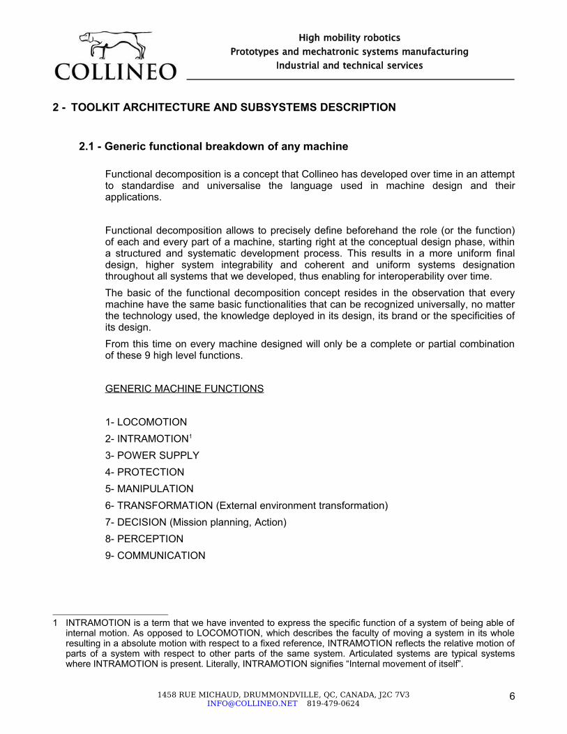
Functional decomposition is a concept that Collineo has developed over time in an attempt to standardise and universalise the language used in machine design and their applications.
Functional decomposition allows to precisely define beforehand the role (or the function) of each and every part of a machine, starting right at the conceptual design phase, within a structured and systematic development process. This results in a more uniform final design, higher system integrability and coherent and uniform systems designation throughout all systems that we developed, thus enabling for interoperability over time.The basic of the functional decomposition concept resides in the observation that every machine have the same basic functionalities that can be recognized universally, no matter the technology used, the knowledge deployed in its design, its brand or the specificities of its design.From this time on every machine designed will only be a complete or partial combination of these 9 high level functions.
GENERIC MACHINE FUNCTIONS
1- LOCOMOTION2- INTRAMOTION1
3- POWER SUPPLY4- PROTECTION5- MANIPULATION6- TRANSFORMATION (External environment transformation)7- DECISION (Mission planning, Action)8- PERCEPTION9- COMMUNICATION
1 INTRAMOTION is a term that we have invented to express the specific function of a system of being able of internal motion. As opposed to LOCOMOTION, which describes the faculty of moving a system in its whole resulting in a absolute motion with respect to a fixed reference, INTRAMOTION reflects the relative motion of parts of a system with respect to other parts of the same system. Articulated systems are typical systems where INTRAMOTION is present. Literally, INTRAMOTION signifies “Internal movement of itself”.
1458 RUE MICHAUD, DRUMMONDVILLE, QC, CANADA, J2C [email protected] 819-479-0624
6
High mobility roboticsPrototypes and mechatronic systems manufacturing
Industrial and technical services

2.2 - Functional breakdown of the toolkit
The micro-hydraulic toolkit is constituted of only 3 of the 10 generic machine functions. Each of these high-level functions represents complex systems with advanced behaviour which can be broken down into numerous lower-level functions with simpler behaviour. In order to result in a high-level function, the arrangement of these lower-level functions have to follow a specific and structured architecture forming a functional breakdown tree.
2.2.1 - Main functional breakdown tree
The main functional breakdown tree of the toolkit is as follows :
LOCOMOTION : Directional wheeled platform| PROPULSION
| TRACTION (x4) : Hydraulic wheel drive| POWER SUPPLY : Hydraulic power supply
| DIRECTION| POWER SUPPLY : Electric power supply
INTRAMOTION : Limbs| ATICULATION (x8) : Hydraulic rotative articulation| TRANSMISSION #1 (x8) : Long structural beam| TRANSMISSION #2 (x8) : Short structural beam| POWER SUPPLY #1 : Electric power supply| POWER SUPPLY #2 : Hydraulic power supply
POWER SUPPLY : Electric power supplyCOMMUNICATION : CANopen network
1458 RUE MICHAUD, DRUMMONDVILLE, QC, CANADA, J2C [email protected] 819-479-0624
7
High mobility roboticsPrototypes and mechatronic systems manufacturing
Industrial and technical services

2.2.2 - Subsidiary functional breakdown trees
Subsidiary functional breakdown trees of the toolkit are as follows :
LOCOMOTION / PROPULSION / TRACTION : Hydraulic wheel drive| ARTICULATION #1 : Wheel rotation
| FASTENING : Wheel aluminium hub| TRANSMISSION : Wheel aluminium rim| JOINT : Sealed ball bearing| ACTUATION
| MOTORISATION : Hydraulic gearmotor| REDUCTION : Harmonic drive| VARIATION #1 : Proportional directional hydraulic valve| VARIATION #2 : Valve electronic drive
| SENSATION : Inductive quadrature encoder| REGULATION : PID compensation| PROTECTION: Low friction lip seal
| ARTICULATION #2 : Wheel tire
LOCOMOTION / PROPULSION / POWER SUPPLY : Hydraulic power supply| GENERATION
| CONVERSION : Hydraulic gearpump| MOTORISATION : DC brushed permanent magnet motor| ACTIVATION : Power relay| ACCUMULATION : Vented Hydraulic tank
| FASTENING : Aluminium frame| SENSATION : Hydraulic pressure sensor| REGULATION : Pressure sensor threshold| FILTRATION : Return line filter (low pressure) | ACCUMULATION : Pressurized bellows accumulator (optional)| TRANSMISSION #1 : Hydraulic pump manifold| TRANSMISSION #2 : Hydraulic valve manifold
1458 RUE MICHAUD, DRUMMONDVILLE, QC, CANADA, J2C [email protected] 819-479-0624
8
High mobility roboticsPrototypes and mechatronic systems manufacturing
Industrial and technical services

LOCOMOTION / DIRECTION / ARTICULATION : Electric rotative articulation| FASTENING : Aluminium housing| TRANSMISSION #1 : Hardened aluminium shaft with internal oil conduits| TRANSMISSION #2 : Aluminium radial beam| TRANSMISSION #3 : Aluminium axial beam| JOINT : Sealed ball bearing| ACTUATION
| MOTORISATION : Permanent magnet brushless DC motor| REDUCTION #1 : Planetary gear assembly| REDUCTION #2 : Worm gear assembly| SENSATION : Hall effect sensors| VARIATION : Advanced unipolar PWM drive for brushless motor
| SENSATION : Wirewound potentiometer| REGULATION : PID compensation
LOCOMOTION / POWER SUPPLY : Electric power supply| CONVERSION : Battery charger (24V)
| ACCUMULATION : Battery (24V)
| FASTENING : Aluminium frame
| SELECTION : Power relay to select power source
| PROTECTION : Fuse (100A)| ACTIVATION : Power switch
INTRAMOTION / ARTICULATION : Hydraulic rotative articulation| FASTENING : Aluminium frame| TRANSMISSION : Aluminium circular flange| JOINT : Sealed ball bearing| ACTUATION
| MOTORISATION : Double vane hydraulic rotary actuator| VARIATION #1 : Proportional directional hydraulic valve| VARIATION #2 : Valve electronic drive
| SENSATION : Wirewound potentiometer| REGULATION : PID compensation
1458 RUE MICHAUD, DRUMMONDVILLE, QC, CANADA, J2C [email protected] 819-479-0624
9
High mobility roboticsPrototypes and mechatronic systems manufacturing
Industrial and technical services

INTRAMOTION / POWER SUPPLY #1 : Electric power supply| CONVERSION : Battery charger (24V)
| ACCUMULATION : Battery (24V)
| FASTENING : Aluminium frame
| SELECTION : Power relay to select power source
| PROTECTION : Fuse (100A)| ACTIVATION : Power switch
INTRAMOTION / POWER SUPPLY #2 : Hydraulic power supply| GENERATION
| CONVERSION : Hydraulic gearpump| MOTORISATION : DC brushed permanent magnet motor| ACTIVATION : Power relay
| FASTENING : Aluminium frame| SENSATION : Hydraulic pressure sensor| REGULATION : Pressure sensor threshold| FILTRATION : Return line filter (low pressure)| ACCUMULATION : Pressurized bellows accumulator (optional)| TRANSMISSION #1 : Hydraulic pump manifold| TRANSMISSION #2 : Hydraulic valve manifold
POWER SUPPLY : Electric power supply| CONVERSION #1 : AC-DC converter (24V)
| CONVERSION #2 : DC-DC converter (12V)
| CONVERSION #3 : DC-DC converter (5V)| FILTRATION : LC filter| PROTECTION : E-switch
Note : some minor functions have been intentionally omitted for further clarity
1458 RUE MICHAUD, DRUMMONDVILLE, QC, CANADA, J2C [email protected] 819-479-0624
10
High mobility roboticsPrototypes and mechatronic systems manufacturing
Industrial and technical services

2.3 - Toolkit's physical subsystems
The micro-hydraulic toolkit is composed of several subsystems. Each subsystem is a physical assembly of different functions that have been gathered together for modularity and interoperability purposes. Physical subsystems cannot always be integrally identified with specific high-level functions since they have to obey to physical and technological constraints. However, the construction of the toolkit subsystems mostly follows the toolkit functional breakdown and only a few functions have been relocated.
1458 RUE MICHAUD, DRUMMONDVILLE, QC, CANADA, J2C [email protected] 819-479-0624
11
High mobility roboticsPrototypes and mechatronic systems manufacturing
Industrial and technical services

2.3.1 - Wheel drive module
Multiplicity : 4
Main functional components :
Functional path TechnologyLOCOMOTION / PROPULSION / TRACTION / ARTICULATION #1 / FASTENING
Wheel aluminium hub
LOCOMOTION / PROPULSION / TRACTION / ARTICULATION #1 / TRANSMISSION
Wheel aluminium rim
LOCOMOTION / PROPULSION / TRACTION / ARTICULATION #1 / JOINT Ball bearingLOCOMOTION / PROPULSION / TRACTION / ARTICULATION #1 / ACTUATION / MOTORISATION
Hydraulic gearmotor
LOCOMOTION / PROPULSION / TRACTION / ARTICULATION #1 / ACTUATION / REDUCTION
Harmonic drive (50:1)
LOCOMOTION / PROPULSION / TRACTION / ARTICULATION #1 / SENSATION
Inductive quadrature encoder
LOCOMOTION / PROPULSION / TRACTION / ARTICULATION #1 / PROTECTION
Low friction lip seal
LOCOMOTION / PROPULSION / TRACTION / ARTICULATION #2 Wheel tire
Physiology :
Operation :Rotation range : unlimited
1458 RUE MICHAUD, DRUMMONDVILLE, QC, CANADA, J2C [email protected] 819-479-0624
12
High mobility roboticsPrototypes and mechatronic systems manufacturing
Industrial and technical services
PORT 1-2-3-4

Speed range : 0.5 ~ 5 km/h (estimated, TBC )Torque range : 0 ~ 25 Nm max.(estimated, TBC )
Connectivity :
Port 1Description : Wheel hub connection Type : MechanicalTechnology : Bolted connection Number : 4Characteristics : Bolt : M6x50mm SHCS plated
Nut : M6 platedWasher : M6 plated AFNOR
Port 2Description : Hydraulic work ports Type : HydraulicTechnology : O-ring boss Number : 2Characteristics : Thread : 9/16 SAE
Port 3Description : Hydraulic drain ports Type : HydraulicTechnology : Flexible low pressure hose Number : 1Characteristics : Diameter ¼ in.
Port 4Description : Wheel sensors connection Type : ElectricTechnology : Plug/socket connection Number : 4Characteristics :
Pin Function Description1 DC supply (12V) Sensors power supply2 DC ground Sensors ground3 Digital output (NPN) First sensor measurement output4 Digital output (NPN) Second sensor measurement output
1458 RUE MICHAUD, DRUMMONDVILLE, QC, CANADA, J2C [email protected] 819-479-0624
13
High mobility roboticsPrototypes and mechatronic systems manufacturing
Industrial and technical services
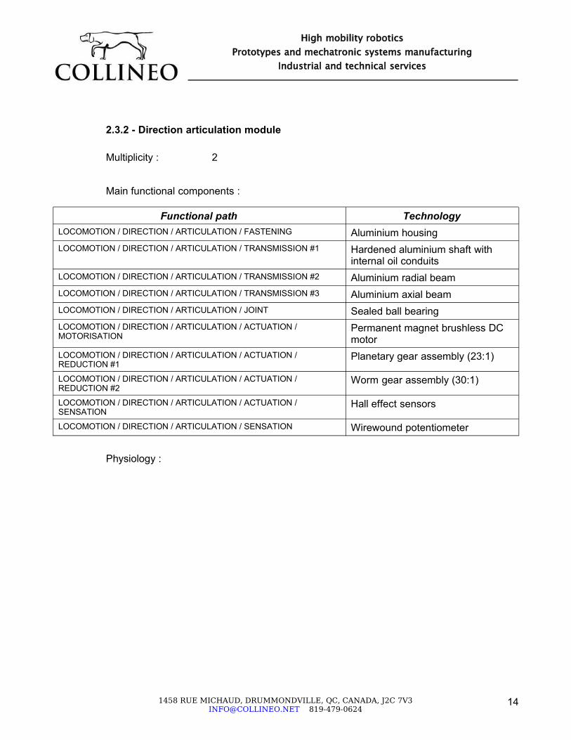
2.3.2 - Direction articulation module
Multiplicity : 2
Main functional components :
Functional path TechnologyLOCOMOTION / DIRECTION / ARTICULATION / FASTENING Aluminium housingLOCOMOTION / DIRECTION / ARTICULATION / TRANSMISSION #1 Hardened aluminium shaft with
internal oil conduitsLOCOMOTION / DIRECTION / ARTICULATION / TRANSMISSION #2 Aluminium radial beamLOCOMOTION / DIRECTION / ARTICULATION / TRANSMISSION #3 Aluminium axial beamLOCOMOTION / DIRECTION / ARTICULATION / JOINT Sealed ball bearingLOCOMOTION / DIRECTION / ARTICULATION / ACTUATION / MOTORISATION
Permanent magnet brushless DC motor
LOCOMOTION / DIRECTION / ARTICULATION / ACTUATION / REDUCTION #1
Planetary gear assembly (23:1)
LOCOMOTION / DIRECTION / ARTICULATION / ACTUATION / REDUCTION #2
Worm gear assembly (30:1)
LOCOMOTION / DIRECTION / ARTICULATION / ACTUATION / SENSATION
Hall effect sensors
LOCOMOTION / DIRECTION / ARTICULATION / SENSATION Wirewound potentiometer
Physiology :
1458 RUE MICHAUD, DRUMMONDVILLE, QC, CANADA, J2C [email protected] 819-479-0624
14
High mobility roboticsPrototypes and mechatronic systems manufacturing
Industrial and technical services

A- DOUBE INTEGRATED SWIVEL JOINT VERSION
B- INDIVIDUAL SWIVEL JOINT VERSION
1458 RUE MICHAUD, DRUMMONDVILLE, QC, CANADA, J2C [email protected] 819-479-0624
15
High mobility roboticsPrototypes and mechatronic systems manufacturing
Industrial and technical services
PORT 1-A
PORT 3
PORT 2-4
PORT 5-6-7
PORT 1-B
PORT 5-6-7
PORT 3
PORT 2-4
PORT 1-A
PORT 1-B (Side)

Operation :Rotation range : -90 ~ 90 degSpeed range : 0 ~ 7 rpm (estimated, TBC)Torque range : Individual swivel config. : 0 ~ 17 Nm (estimated, TBC) Double swivel config. : 0 ~ 10 Nm (estimated, TBC)
Connectivity :
Port 1Description : Articulation housing connection Type : MechanicalTechnology : Bolted connection Number : 8Characteristics : Bolt : M4x20mm Hex head
Washer : M4 plated AFNOR
Port 2Description : Articulation output connection (to wheel drive) Type : MechanicalTechnology : Bolted connection Number : 4Characteristics : Bolt : M6x25mm SHCS
Washer : M4 AFNOR plated
Port 3Description : Traction hydraulic work ports - valve side Type : HydraulicTechnology : JIC fittings Number : 2Characteristics : 9/16 threads, Thermoplastic flexible hose 5/16
Port 4Description : Traction hydraulic work ports - wheel side Type : HydraulicTechnology : O-ring face compression sealing Number : 2Characteristics : 5mm I.D. O ring, - Internal rigid tubing O.D. ¼ in.
1458 RUE MICHAUD, DRUMMONDVILLE, QC, CANADA, J2C [email protected] 819-479-0624
16
High mobility roboticsPrototypes and mechatronic systems manufacturing
Industrial and technical services

Port 5Description : Direction motor power connection Type : ElectricTechnology : Plug/socket connection Number : 3Characteristics :
Pin Function Description1 DC analog input Motor winding 12 DC analog input Motor winding 23 DC analog input Motor winding 3
Port 6Description : Direction motor sensors connection Type : ElectricTechnology : Plug/socket connection Number : 5Characteristics :
Pin Function Description1 DC supply (5V) Hall sensors power supply2 DC ground Hall sensors ground3 Digital output (NPN) Hall sensors output 14 Digital output (NPN) Hall sensors output 25 Digital output (NPN) Hall sensors output 3
Port 7Description : Direction sensor connection Type : ElectricTechnology : Plug/socket connection Number : 3Characteristics :
Pin Function Description1 DC supply (12V) Potentiometer power supply2 DC ground Potentiometer ground3 DC analog output Potentiometer measurement output
1458 RUE MICHAUD, DRUMMONDVILLE, QC, CANADA, J2C [email protected] 819-479-0624
17
High mobility roboticsPrototypes and mechatronic systems manufacturing
Industrial and technical services

2.3.3 - Intramotion articulation module
Multiplicity : 8
Main functional components :
Functional path TechnologyINTRAMOTION / ARTICULATION / FASTENING Aluminium frameINTRAMOTION / ARTICULATION / TRANSMISSION Aluminium circular flangeINTRAMOTION / ARTICULATION / JOINT Ball bearingINTRAMOTION / ARTICULATION / ACTUATION / MOTORISATION Double vane hydraulic rotary
actuatorINTRAMOTION / ARTICULATION / SENSATION Wirewound potentiometer
Physiology :
Operation :Rotation range : 0 ~ 100 degSpeed range : 0 ~ 100 °/s (estimated, TBC)Torque range : 0 ~ 500 Nm (estimated, TBC)
1458 RUE MICHAUD, DRUMMONDVILLE, QC, CANADA, J2C [email protected] 819-479-0624
18
High mobility roboticsPrototypes and mechatronic systems manufacturing
Industrial and technical services
PORT 4PORT 2
PORT 1 PORT 3

Connectivity :
Port 1Description : Articulation frame connection Type : MechanicalTechnology : Bolted connection + shear sleeve 7x10mm Number : 8Characteristics : Bolt : M6x25mm Hex head
Nut : M6 platedWasher : M6 plated AFNOR
Port 2Description : Articulation flange connection Type : MechanicalTechnology : Bolted connection + shear sleeve 7x10mm Number : 8Characteristics : Bolt : M6x25mm Hex head
Nut : M6 platedWasher : M6 plated AFNOR
Port 3Description : Hydraulic rotary actuator ports Type : HydraulicTechnology : JIC fittings Number : 2Characteristics : 9/16 threads, Thermoplastic flexible hose 5/16
Port 4Description : Articulation sensor connection Type : ElectricTechnology : Plug/socket connection Number : 3Characteristics :
Pin Function Description1 DC supply (12V) Potentiometer power supply2 DC ground Potentiometer ground3 DC analog output Potentiometer measurement output
1458 RUE MICHAUD, DRUMMONDVILLE, QC, CANADA, J2C [email protected] 819-479-0624
19
High mobility roboticsPrototypes and mechatronic systems manufacturing
Industrial and technical services

2.3.4 - Traction variation module
Multiplicity : 4
Main functional components :
Functional path TechnologyLOCOMOTION / PROPULSION / TRACTION / ARTICULATION #1 / ACTUATION / VARIATION #1
Proportional directional hydraulic valve
LOCOMOTION / PROPULSION / TRACTION / ARTICULATION #1 / ACTUATION / VARIATION #2
Valve electronic drive
LOCOMOTION / PROPULSION / TRACTION / ARTICULATION #1 / ACTUATION / TRANSMISSION
Hydraulic manifold
Physiology :
1458 RUE MICHAUD, DRUMMONDVILLE, QC, CANADA, J2C [email protected] 819-479-0624
20
High mobility roboticsPrototypes and mechatronic systems manufacturing
Industrial and technical services
SHOWN IN GROUP OF 2 FOR ASSEMBLY PURPOSES
PORT 1
PORT 3
PORT 2
PORT 4
PORT 5

Operation :Voltage range : 21 ~ 30 VCurrent range : 0 ~ 540 mAPressure range : 0 ~315 bar (port P, A and B), 0 ~160 bar (port T)
Connectivity :
Port 1Description : Manifold bottom connection Type : MechanicalTechnology : Bolted connection Number : 4Characteristics : Bolt : M6x25mm Hex head
Nut : M6 platedWasher : M6 plated AFNOR
Port 2Description : Hydraulic supply port Type : HydraulicTechnology : JIC fittings Number : 2Characteristics : 9/16 threads, Thermoplastic flexible hose 5/16
Port 3Description : Hydraulic return port Type : HydraulicTechnology : JIC fittings Number : 3Characteristics : 9/16 threads, Low pressure (300 PSI) rubber flexible hose 3/8
Port 4Description : Hydraulic work ports Type : HydraulicTechnology : JIC fittings Number : 2Characteristics : 9/16 threads, Thermoplastic flexible hose 5/16
Port 5Description : Valve electric connection Type : Electric
1458 RUE MICHAUD, DRUMMONDVILLE, QC, CANADA, J2C [email protected] 819-479-0624
21
High mobility roboticsPrototypes and mechatronic systems manufacturing
Industrial and technical services

Port 5Technology : Plug/socket connection Number : 4Characteristics :
Pin Function Description1 DC supply (24V) Valve power supply2 DC ground Valve power ground3 DC analog input Valve command signal4 DC analog common Valve command reference
1458 RUE MICHAUD, DRUMMONDVILLE, QC, CANADA, J2C [email protected] 819-479-0624
22
High mobility roboticsPrototypes and mechatronic systems manufacturing
Industrial and technical services

2.3.5 - Intramotion variation module
Multiplicity : 8
Main functional components :
Functional path TechnologyINTRAMOTION / ARTICULATION / ACTUATION / VARIATION #1 Proportional directional hydraulic
valveINTRAMOTION / ARTICULATION / ACTUATION / VARIATION #2 Valve electronic driveINTRAMOTION / ARTICULATION / ACTUATION / TRANSMISSION Hydraulic manifold
Physiology :
1458 RUE MICHAUD, DRUMMONDVILLE, QC, CANADA, J2C [email protected] 819-479-0624
23
High mobility roboticsPrototypes and mechatronic systems manufacturing
Industrial and technical services
SHOWN IN GROUP OF 2 FOR ASSEMBLY PURPOSES
PORT 1
PORT 3
PORT 2
PORT 4
PORT 5

Operation :Voltage range : 21 ~ 30 VCurrent range : 0 ~ 540 mAPressure range : 0 ~315 bar (port P, A and B), 0 ~160 bar (port T)
Connectivity :
Port 1Description : Manifold bottom connection Type : MechanicalTechnology : Bolted connection Number : 4Characteristics : Bolt : M6x25mm Hex head
Nut : M6 platedWasher : M6 plated AFNOR
Port 2Description : Hydraulic supply port Type : HydraulicTechnology : JIC fittings Number : 2Characteristics : 9/16 threads, Thermoplastic flexible hose 5/16
Port 3Description : Hydraulic return port Type : HydraulicTechnology : JIC fittings Number : 3Characteristics : 9/16 threads, Low pressure (300 PSI) rubber flexible hose 3/8
Port 4Description : Hydraulic work ports Type : HydraulicTechnology : JIC fittings Number : 2Characteristics : 9/16 threads, Thermoplastic flexible hose 5/16
Port 5Description : Valve electric connection Type : ElectricTechnology : Plug/socket connection Number : 4
1458 RUE MICHAUD, DRUMMONDVILLE, QC, CANADA, J2C [email protected] 819-479-0624
24
High mobility roboticsPrototypes and mechatronic systems manufacturing
Industrial and technical services

Port 5Characteristics :
Pin Function Description1 DC supply (24V) Valve power supply2 DC ground Valve power ground3 DC analog input Valve command signal4 DC analog common Valve command reference
1458 RUE MICHAUD, DRUMMONDVILLE, QC, CANADA, J2C [email protected] 819-479-0624
25
High mobility roboticsPrototypes and mechatronic systems manufacturing
Industrial and technical services

2.3.6 - Propulsion hydraulic power supply module
Multiplicity : 1
Main functional components :
Functional path TechnologyLOCOMOTION / PROPULSION / POWER SUPPLY / GENERATION Hydraulic generation unitLOCOMOTION / PROPULSION / POWER SUPPLY / FASTENING Aluminium frameLOCOMOTION / PROPULSION / POWER SUPPLY / SENSATION Propulsion hydraulic pressure
sensorLOCOMOTION / PROPULSION / POWER SUPPLY / FILTRATION Low pressure return line filterLOCOMOTION / PROPULSION / POWER SUPPLY / ACCUMULATION Pressurized bellows accumulator
(optional)LOCOMOTION / PROPULSION / POWER SUPPLY / TRANSMISSION #1 Hydraulic pump manifold
Physiology :
Operation :
1458 RUE MICHAUD, DRUMMONDVILLE, QC, CANADA, J2C [email protected] 819-479-0624
26
High mobility roboticsPrototypes and mechatronic systems manufacturing
Industrial and technical services
PORT 2PORT 1
PORT 6
Digital pressure sensor/indicator
NOTE - PORT 4 - DRAIN LINE PASSED THROUGH TANK VENT
Low pressure filter
PORT 3
PORT 4
PORT 5

Voltage range : 0 ~24 VCurrent range : refer to product specificationsFlow range : 0 ~8.6 L/minPressure range : refer to product specifications
Connectivity :
Port 1Description : Frame connection Type : MechanicalTechnology : Bolted connection + shear sleeve 7x10mm Number : 4Characteristics : Bolt : M6x25mm Hex head
Nut : M6 platedWasher : M6 plated AFNOR
Port 2Description : Hydraulic supply port Type : HydraulicTechnology : JIC fittings Number : 3Characteristics : 9/16 threads, Thermoplastic flexible hose 5/16
Port 3Description : Hydraulic return port Type : HydraulicTechnology : JIC fittings Number : 3Characteristics : 9/16 threads, Low pressure (300 PSI) rubber flexible hose 3/8
Port 4Description : Hydraulic drain port Type : HydraulicTechnology : Hole Number : 1Characteristics : Tank vent
Port 5Description : Pump motor connection Type : ElectricTechnology : Bolted connection Number : 2
1458 RUE MICHAUD, DRUMMONDVILLE, QC, CANADA, J2C [email protected] 819-479-0624
27
High mobility roboticsPrototypes and mechatronic systems manufacturing
Industrial and technical services

Port 5Characteristics :
Pin Function Description1 DC analog input Motor positive terminal2 DC ground Motor negative terminal
Port 6Description : Pressure sensor connection Type : ElectricTechnology : Plug/socket connection Number : 4Characteristics :
Pin Function Description1 DC supply (24V) Sensor power supply2 DC analog output Sensor measurement output3 DC ground Sensor ground4 Digital output (PNP) Sensor switch output
1458 RUE MICHAUD, DRUMMONDVILLE, QC, CANADA, J2C [email protected] 819-479-0624
28
High mobility roboticsPrototypes and mechatronic systems manufacturing
Industrial and technical services

2.3.7 - Intramotion hydraulic power supply module
Multiplicity : 1
Main functional components :
Functional path TechnologyINTRAMOTION / POWER SUPPLY / GENERATION Hydraulic generation unitINTRAMOTION / POWER SUPPLY / FASTENING Aluminium frameINTRAMOTION / POWER SUPPLY / SENSATION Propulsion hydraulic pressure
sensorINTRAMOTION / POWER SUPPLY / FILTRATION Low pressure return line filterINTRAMOTION / POWER SUPPLY / ACCUMULATION Pressurized bellows accumulator
(optional)INTRAMOTION / POWER SUPPLY / TRANSMISSION #1 Hydraulic pump manifold
Physiology :
1458 RUE MICHAUD, DRUMMONDVILLE, QC, CANADA, J2C [email protected] 819-479-0624
29
High mobility roboticsPrototypes and mechatronic systems manufacturing
Industrial and technical services
PORT 3
PORT 2
NO DRAIN LINE NEEDED FOR THIS POWER SUPPLY UNIT
Low pressure filter
PORT 1
PORT 6
PORT 5
Accumulator
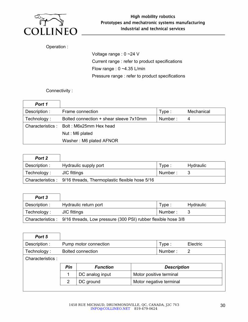
Operation :Voltage range : 0 ~24 VCurrent range : refer to product specificationsFlow range : 0 ~4.35 L/minPressure range : refer to product specifications
Connectivity :
Port 1Description : Frame connection Type : MechanicalTechnology : Bolted connection + shear sleeve 7x10mm Number : 4Characteristics : Bolt : M6x25mm Hex head
Nut : M6 platedWasher : M6 plated AFNOR
Port 2Description : Hydraulic supply port Type : HydraulicTechnology : JIC fittings Number : 3Characteristics : 9/16 threads, Thermoplastic flexible hose 5/16
Port 3Description : Hydraulic return port Type : HydraulicTechnology : JIC fittings Number : 3Characteristics : 9/16 threads, Low pressure (300 PSI) rubber flexible hose 3/8
Port 5Description : Pump motor connection Type : ElectricTechnology : Bolted connection Number : 2Characteristics :
Pin Function Description1 DC analog input Motor positive terminal2 DC ground Motor negative terminal
1458 RUE MICHAUD, DRUMMONDVILLE, QC, CANADA, J2C [email protected] 819-479-0624
30
High mobility roboticsPrototypes and mechatronic systems manufacturing
Industrial and technical services

Port 6Description : Pressure sensor connection Type : ElectricTechnology : Plug/socket connection Number : 4Characteristics :
Pin Function Description1 DC supply (24V) Sensor power supply2 DC analog output Sensor measurement output3 DC ground Sensor ground4 Digital output (PNP) Sensor switch output
1458 RUE MICHAUD, DRUMMONDVILLE, QC, CANADA, J2C [email protected] 819-479-0624
31
High mobility roboticsPrototypes and mechatronic systems manufacturing
Industrial and technical services

2.3.8 - Electric power accumulation module
Multiplicity : 2
Main functional components :
Functional path TechnologyLOCOMOTION / POWER SUPPLY / ACCUMULATION
INTRAMOTION / POWER SUPPLY #1 / ACCUMULATIONAcid-gel batteries
LOCOMOTION / POWER SUPPLY / FASTENING
INTRAMOTION / POWER SUPPLY #1 / FASTENINGAluminium frame
Physiology :
1458 RUE MICHAUD, DRUMMONDVILLE, QC, CANADA, J2C [email protected] 819-479-0624
32
High mobility roboticsPrototypes and mechatronic systems manufacturing
Industrial and technical services
Valence U1 Batteries
ALTERNATE MOUNTING OF BATTERIES – REMOVE HYDRAULICS AND USE FRAME AS BATTERY HOLDER
Standard Acid-Gel batteries Hydraulic power unit Frame
USE NYLON STRAPS IN SLOTS TO HOLD BATTERIES

2.3.9 - Electronic power supply module
Multiplicity : 1
Main functional components :
Functional path TechnologyPOWER SUPPLY / GENERATION #1 DC-DC converterPOWER SUPPLY / GENERATION #2 DC-DC converterPOWER SUPPLY / FILTRATION LC filterPOWER SUPPLY / PROTECTION Plastic enclosure
Physiology :
Operation :Voltage input range : 21 ~ 30 VCurrent input range : 0 ~ 20 A
1458 RUE MICHAUD, DRUMMONDVILLE, QC, CANADA, J2C [email protected] 819-479-0624
33
High mobility roboticsPrototypes and mechatronic systems manufacturing
Industrial and technical services
Electronic power supply module
SHOWN ASSEMBLED ON TOOLKIT UPPER PLATFORM
PORT 1
PORT 2-3-4

Connectivity :
Port 1Description : Batteries connection Type : ElectricTechnology : Plug/socket connection (Molex Mini-Fit Sr.) Number : 4Characteristics :
Pin Function Description1 DC analog input Locomotion electronic power supply2 DC ground Locomotion electronic power ground3 DC analog input Intramotion electronic power supply4 DC ground Intramotion electronic power ground
Port 2Description : Electronic filtered 24V power supply Type : ElectricTechnology : Plug/socket connection (Molex Mini-Fit Jr.) Number : 12Characteristics :
Pin Function Description1 not used2 DC ground Ground3 DC ground Ground4 DC ground Ground5 DC ground Ground6 DC ground Ground7 not used8 DC analog output 24V filtered power supply (1A max)9 DC analog output 24V filtered power supply (1A max)
10 DC analog output 24V filtered power supply (5A max)11 DC analog output 24V filtered power supply (5A max)12 DC analog output 24V filtered power supply (5A max)
1458 RUE MICHAUD, DRUMMONDVILLE, QC, CANADA, J2C [email protected] 819-479-0624
34
High mobility roboticsPrototypes and mechatronic systems manufacturing
Industrial and technical services

Port 3Description : Electronic 12V power supply Type : ElectricTechnology : Plug/socket connection (Molex Mini-Fit Jr.) Number : 10Characteristics :
Pin Function Description1 DC ground Ground2 DC ground Ground3 DC ground Ground4 DC ground Ground5 DC ground Ground6 DC analog output 12V power supply (1A max)7 DC analog output 12V power supply (1A max)8 DC analog output 12V power supply (1A max)9 DC analog output 12V power supply (1A max)
10 DC analog output 12V power supply (1A max)
Port 4Description : Electronic 5V power supply Type : ElectricTechnology : Plug/socket connection (Molex Mini-Fit Jr.) Number : 10Characteristics :
Pin Function Description1 DC ground Ground2 DC ground Ground3 DC ground Ground4 DC ground Ground5 DC ground Ground6 DC analog output 5V power supply (1A max)7 DC analog output 5V power supply (1A max)8 DC analog output 5V power supply (1A max)9 DC analog output 5V power supply (1A max)
10 DC analog output 5V power supply (1A max)
1458 RUE MICHAUD, DRUMMONDVILLE, QC, CANADA, J2C [email protected] 819-479-0624
35
High mobility roboticsPrototypes and mechatronic systems manufacturing
Industrial and technical services

2.3.10 - Electric power supply regulation module
Multiplicity : 2
Main functional components :
Functional path TechnologyLOCOMOTION / POWER SUPPLY / SELECTION
INTRAMOTION / POWER SUPPLY #1 / SELECTIONPower relay
LOCOMOTION / PROPULSION / POWER SUPPLY / GENERATION / ACTIVATION
INTRAMOTION / POWER SUPPLY #2 / GENERATION / ACTIVATION
Power relay
LOCOMOTION / POWER SUPPLY / FASTENING
INTRAMOTION / POWER SUPPLY / FASTENINGAluminium frame
LOCOMOTION / POWER SUPPLY / PROTECTION
INTRAMOTION / POWER SUPPLY / PROTECTIONPlastic enclosure
Physiology :
1458 RUE MICHAUD, DRUMMONDVILLE, QC, CANADA, J2C [email protected] 819-479-0624
36
High mobility roboticsPrototypes and mechatronic systems manufacturing
Industrial and technical services

Operation :Voltage range : 21 ~ 30 VCurrent range : 0 ~ 100 A
Connectivity :
Port 1Description : Battery and hydraulic pump connection Type : ElectricTechnology : Screw terminal (AWG 4) Number : 4Characteristics :
Pin Function Description1 DC analog Battery positive terminal2 DC ground Battery negative terminal3 DC analog output Pump motor positive terminal4 DC ground Pump motor negative terminal
Port 2Description : Charger and converter connection Type : ElectricTechnology : Screw terminal (AWG 10) Number : 6Characteristics :
Pin Function Description1 DC analog input AC/DC converter positive terminal2 DC ground AC/DC converter negative terminal3 DC analog input Battery charger positive terminal4 DC ground Battery charger negative terminal5 DC analog output Electronic power supply6 DC ground Electronic power ground
1458 RUE MICHAUD, DRUMMONDVILLE, QC, CANADA, J2C [email protected] 819-479-0624
37
High mobility roboticsPrototypes and mechatronic systems manufacturing
Industrial and technical services

Port 3Description : E-stop connection Type : ElectricTechnology : Wire connection Number : 2Characteristics :
Port 4Description : Pressure sensor digital output connection Type : ElectricTechnology : Plug/socket connection Number : 1Characteristics :
1458 RUE MICHAUD, DRUMMONDVILLE, QC, CANADA, J2C [email protected] 819-479-0624
38
High mobility roboticsPrototypes and mechatronic systems manufacturing
Industrial and technical services

2.3.11 - Electronic and processing module (prototype)
Multiplicity : 1
Main functional components :
Functional path TechnologyPROCESSING WildFire single board computerCONDITIONNING Electronic interface boardTRANSMISSION Electronic connexion boardPROTECTION Aluminium enclosureLOCOMOTION / PROPULSION / TRACTION / ARTICULATION #1 / REGULATION (x1)
PID compensation
LOCOMOTION / DIRECTION / ARTICULATION / ACTUATION / VARIATION (x1)
Advanced unipolar PWM drive for brushless motor
LOCOMOTION / DIRECTION / ARTICULATION / REGULATION (x1) PID compensationINTRAMOTION / ARTICULATION / REGULATION (x2) PID compensation
Physiology :
1458 RUE MICHAUD, DRUMMONDVILLE, QC, CANADA, J2C [email protected] 819-479-0624
39
High mobility roboticsPrototypes and mechatronic systems manufacturing
Industrial and technical services

Operation :Voltage input range : 12 and 24 VCommunication : CANopen network
Connectivity :
Port 1Description : Electronic 24V power supply Type : ElectricTechnology : Plug/socket connection (Molex Mini-Fit Jr.) Number : 12Characteristics :
Pin Function Description1 not used2 DC ground Ground3 DC ground Ground4 DC ground Ground5 DC ground Ground6 DC ground Ground7 not used8 DC analog output 24V filtered power supply (1A max)9 DC analog output 24V filtered power supply (1A max)
10 DC analog output 24V filtered power supply (5A max)11 DC analog output 24V filtered power supply (5A max)12 DC analog output 24V filtered power supply (5A max)
Port 2Description : Electronic 12V power supply Type : ElectricTechnology : Plug/socket connection (Molex Mini-Fit Jr.) Number : 10
1458 RUE MICHAUD, DRUMMONDVILLE, QC, CANADA, J2C [email protected] 819-479-0624
40
High mobility roboticsPrototypes and mechatronic systems manufacturing
Industrial and technical services

Port 2Characteristics :
Pin Function Description1 DC ground Ground2 DC ground Ground3 DC ground Ground4 DC ground Ground5 DC ground Ground6 DC analog output 12V power supply (1A max)7 DC analog output 12V power supply (1A max)8 DC analog output 12V power supply (1A max)9 DC analog output 12V power supply (1A max)
10 DC analog output 12V power supply (1A max)
Port 3Description : E-stop connection Type : ElectricTechnology : Wire connection Number : 2Characteristics :
Port 4, 6Description : Connection to Locomotion and Intramotion
electric power supply regulation modulesType : Electric
Technology : Plug/socket connection Number : 4Characteristics :
Pin Function Description1 Digital input E-stop signal2 Digital input (NPN) Logic enable signal3 Digital input (PNP) Pressure sensor digital output4 DC ground Electronic ground
1458 RUE MICHAUD, DRUMMONDVILLE, QC, CANADA, J2C [email protected] 819-479-0624
41
High mobility roboticsPrototypes and mechatronic systems manufacturing
Industrial and technical services

Port 5, 7Description : Connection to Propulsion and Intramotion
hydraulic pressure sensorsType : Electric
Technology : Plug/socket connection Number : 4Characteristics :
Pin Function Description1 DC supply (24V) Sensor power supply2 DC ground Sensor ground3 DC analog output Sensor measurement output4 Digital output (PNP) Sensor switch output
Port 8, 10, 12Description : Hydraulic valve electric connection Type : ElectricTechnology : Plug/socket connection Number : 4Characteristics :
Pin Function Description1 DC supply (24V) Valve power supply2 DC ground Valve power ground3 DC analog input Valve command signal4 DC analog common Valve command reference
Port 9, 11Description : Articulation sensor connection Type : ElectricTechnology : Plug/socket connection Number : 3Characteristics :
Pin Function Description1 DC supply (12V) Potentiometer power supply2 DC ground Potentiometer ground3 DC analog output Potentiometer measurement output
1458 RUE MICHAUD, DRUMMONDVILLE, QC, CANADA, J2C [email protected] 819-479-0624
42
High mobility roboticsPrototypes and mechatronic systems manufacturing
Industrial and technical services

Port 13Description : Wheel sensors connection Type : ElectricTechnology : Plug/socket connection Number : 4Characteristics :
Pin Function Description1 DC supply (12V) Sensors power supply2 DC ground Sensors ground3 Digital output (NPN) First sensor measurement output4 Digital output (NPN) Second sensor measurement output
Port 14Description : Direction motor power connection Type : ElectricTechnology : Plug/socket connection Number : 3Characteristics :
Pin Function Description1 DC analog input Motor winding 12 DC analog input Motor winding 23 DC analog input Motor winding 3
Port 15Description : Direction sensors connection Type : ElectricTechnology : Plug/socket connection Number : 8
1458 RUE MICHAUD, DRUMMONDVILLE, QC, CANADA, J2C [email protected] 819-479-0624
43
High mobility roboticsPrototypes and mechatronic systems manufacturing
Industrial and technical services

Port 15Characteristics :
Pin Function Description1 DC supply (5V) Hall sensors power supply2 DC ground Hall sensors ground3 Digital output (NPN) Hall sensors output 14 Digital output (NPN) Hall sensors output 25 Digital output (NPN) Hall sensors output 36 DC supply (12V) Potentiometer power supply7 DC ground Potentiometer ground8 DC analog output Potentiometer measurement output
Port 16Description : CAN communication connection Type : ElectricTechnology : Plug/socket connection (DB9) Number : 3Characteristics :
Pin Function Description7 DC digital CAN High2 DC digital CAN Low
3, 6 DC ground CAN ground
1458 RUE MICHAUD, DRUMMONDVILLE, QC, CANADA, J2C [email protected] 819-479-0624
44
High mobility roboticsPrototypes and mechatronic systems manufacturing
Industrial and technical services

3 - ASSEMBLY AND POSSIBLE KIT CONFIGURATIONS
3.1 - Individual connections
3.1.1 - Mechanical connection standard
To ensure minimal weight of the toolkit, we have chosen to use smaller bolts and support the loads with smaller, lighter shear bushings. This also enabled to standardize most of the toolkit's nuts and bolts throughout the toolkit, even where higher loads were to be carried.
1458 RUE MICHAUD, DRUMMONDVILLE, QC, CANADA, J2C [email protected] 819-479-0624
45
High mobility roboticsPrototypes and mechatronic systems manufacturing
Industrial and technical services
Standard 6mm and 10 mm shear bushing
bolting system
M6 Hexagonal bolts- Variable Length -
10mm O.D. X 6mm I.D. Bushing system
- Variable Length -M6 Washer – Small
diameter « AFNOR » Type
M6 Nut

1458 RUE MICHAUD, DRUMMONDVILLE, QC, CANADA, J2C [email protected] 819-479-0624
46
High mobility roboticsPrototypes and mechatronic systems manufacturing
Industrial and technical services
B - Connection modules Circular bolting pattern
A - Connection modules LARGE rectangular bolting pattern
Standard MECHANICAL bolting patterns
3 types only (A-B-C)
C - Connection modules SMALL rectangular bolting
pattern

3.1.2 - Hydraulic connection standard
All replaceable hydraulic ports have been standardized to 9/16 SAE thread for screwing into aluminium, Including pressure and return lines, and 9/16 JIC ends for the hose connection side. The JIC Standard can be assembled and disassembled many times easily without any leakage problems.Return lines use 9/16 SAE thread at the fittings and 3/8 in I.D. Flexible low pressure hoses and adequate porting.Pressure lines use 9/16 SAE thread at the fittings and 5/16 in I.D. Flexible high pressure thermoplastic hoses and shows adequate adequate porting where required.A colour code was also respected in that all hoses have a specific type and colour to simplify the user's work.
– Pressure lines – Black
– Return lines – Blue
– Drain lines – Transparent
1458 RUE MICHAUD, DRUMMONDVILLE, QC, CANADA, J2C [email protected] 819-479-0624
47
High mobility roboticsPrototypes and mechatronic systems manufacturing
Industrial and technical services
HYDRAULIC PRESSURE LINE (black)
HYDRAULIC RETURN LINE (blue)

3.2 - Assembly techniques and hints
– Insert ALL bolts first, without tightening them. Tighten in a star pattern only last
– Don't struggle. When you have to put extra force to unscrew or move something, check first if it's not blocked in any way.
– ALWAYS use the proper tools. Otherwise you end up stripping or damaging your equipment.
– Prepare your tools and material before starting assembly. Bins (plastic or cardboard) and bags to keep small parts organized is a must
– Tight cables and hoses with the proper keys
– In some cases, doing a preliminary assembly helps understand the structure and the functioning of the device. Once this is done, we can proceed with the final assembly of the device
– Always make sure the assembly surface on the worktable is cleaned from dirt and dust. This is important for all assembly but is MANDATORY for hydraulics
– Clean assembly surfaces, hands and surroundings of mounting surfaces of components to prevent contamination inside mechanical sub-assemblies or hydraulic devices
– Use lint-free rags for cleaning
REMINDER OF THE MOST IMPORTANT RULES
- DONT STRUGGLE with the parts- WORK IN A CLEAN ENVIRONMENT all the time
1458 RUE MICHAUD, DRUMMONDVILLE, QC, CANADA, J2C [email protected] 819-479-0624
48
High mobility roboticsPrototypes and mechatronic systems manufacturing
Industrial and technical services

3.3 - Assembly examples
3.3.1 - Leg type 1 assembly (straight locomotion – no direction module)
1. Prepare for assembly a wheel drive unit, a long ”Extension section” and a connecting flange “Wheel drive conversion”
2. Screw in the 2 JIC fittings. Put the two 5mm O rings in place between the flanges. Screw in the flange to the wheel drive body using 4 x M6 x 35mm SHCS bolts
3. Install the hoses for the leg on the fittings – Tighten properly4. Use M6 Hex bolts inserted from the top to bolt the long extension sections to the
connecting flange, using nuts on the outside to tighten it5. Install the Shoulder connection facing outward (the back flat surface aligned with
the hollowed side of the tubing)
1458 RUE MICHAUD, DRUMMONDVILLE, QC, CANADA, J2C [email protected] 819-479-0624
49
High mobility roboticsPrototypes and mechatronic systems manufacturing
Industrial and technical services
32 41
5
Direction of inserting the
M6 bolts
Direction of inserting the
M6 bolts

6. Bolt an articulation module with 4 bolts only (for now) to the shoulder connection module
7. Pre-assemble the upper leg section module as shown, using 2 shoulder connection modules and a short extension module
8. Assemble the upper leg section to the other flange of the already installed articulation module on the lower leg section. The actuator must point outwards. Assemble a second articulation module facing inwards on the other articulation module's flange.
9. Assemble hydraulic hoses on the knee actuator. Pass the hoses to the upper part of the leg
1458 RUE MICHAUD, DRUMMONDVILLE, QC, CANADA, J2C [email protected] 819-479-0624
50
High mobility roboticsPrototypes and mechatronic systems manufacturing
Industrial and technical services
76 98

10. Pre-assemble a double-circuit manifold assembly with a shoulder internal modular mounting plate. Install the modular mounting plate into the shoulder recess. Leave the modular plate unscrewed
11. Connect hoses to the manifold unit12. When the hoses are connected and tightened, only then, bolt the base connecting
plate to the bottom of the shoulder recess
1458 RUE MICHAUD, DRUMMONDVILLE, QC, CANADA, J2C [email protected] 819-479-0624
51
High mobility roboticsPrototypes and mechatronic systems manufacturing
Industrial and technical services
12
10 11

1. Bolt the two manifolds together and make sure the two o rings are in place and well placed before tightening the manifolds together
2. Bolt the assembled manifold unit to the modular shoulder manifold connecting plate
3. Assemble the NG3 valves on the manifolds. Verify if the o rings of the bottom surface of the valve are well in place
1458 RUE MICHAUD, DRUMMONDVILLE, QC, CANADA, J2C [email protected] 819-479-0624
52
High mobility roboticsPrototypes and mechatronic systems manufacturing
Industrial and technical services
1
3Wandfluh Valve NG3
Separate circuits by plugging the two blocks side by side
2
Shoulder modular connection plate

3.3.2 - Leg type 2 assembly (with direction module)
DIRECTION MODULE ASSEMBLY
1. Assemble the direction module with the leg connection bracket. Also prepare the manifold connector plate with the Swagelock fittings and Cable grips.
2. Connect rigid hydraulic tubing to the fittings of the manifold connector plate. It might be useful at that moment to unscrew the top part of the rigid tubing to tighten the lower part first.
3. Align parts and insert M6 SHCS bolts as indicated. Tight top part of the rigid hydraulic tubing when everything is assembled in place
1458 RUE MICHAUD, DRUMMONDVILLE, QC, CANADA, J2C [email protected] 819-479-0624
53
High mobility roboticsPrototypes and mechatronic systems manufacturing
Industrial and technical services
21 3
Direction of inserting the
M6 bolts
Fittings and connectors
first
leg connection
bracket

1. Install hydraulic hoses on the leg as per the same instructions of leg Type 1. 2. Install hoses and electronic wiring on the direction module last. Leave the hoses
and wires dangling for later connection with valves and drives located on the top surface of the toolkit
1458 RUE MICHAUD, DRUMMONDVILLE, QC, CANADA, J2C [email protected] 819-479-0624
54
High mobility roboticsPrototypes and mechatronic systems manufacturing
Industrial and technical services
21
FINISHED ASSEMBLY OF THE TYPE 2 LEG (WITH DIRECTION MODULES)

1. Regroup 4 LONG leg extensions and 4 tube adaptation plates. Assemble 2 subgroups as shown. Leave the top corner and bottom bolt hole empty. These will be bolted WITH the main body frames later. Do not tight the bolts fully at this point
2. Fix the 2 central body sub-assemblies to the main body frames. Use long M6 bolts to connect the assemblies at the TOP and BOTTOM corners. The bolt must pass through the Main body AND the adaptation plate AND the Extension flange. Do not tight the bolts fully at this point
3. Install the battery plate4. Install the second main body frames and tighten all bolts properly
1458 RUE MICHAUD, DRUMMONDVILLE, QC, CANADA, J2C [email protected] 819-479-0624
55
High mobility roboticsPrototypes and mechatronic systems manufacturing
Industrial and technical services
1 2
3 4
Top corner bolt hole
Bottom corner bolt
hole
Battery plate

5. Install batteries and use nylon straps passed through slots in the battery plate to hold the batteries in the vertical and the horizontal axis
6. Install top cover plate over the batteries. Depending on your toolkit assembly configuration, you might want to install the top plate later when all hydraulics are bolted to it
1458 RUE MICHAUD, DRUMMONDVILLE, QC, CANADA, J2C [email protected] 819-479-0624
56
High mobility roboticsPrototypes and mechatronic systems manufacturing
Industrial and technical services
5 6

3.3.3 - Complete toolkit assembly
1458 RUE MICHAUD, DRUMMONDVILLE, QC, CANADA, J2C [email protected] 819-479-0624
57
High mobility roboticsPrototypes and mechatronic systems manufacturing
Industrial and technical services
2
1
Prepare the 4 legs, making sure you have 2 x Type 1 legs and 2 x Type 2 legs and that both sets have right handed assemblies and 2 x left handed assemblies
Install the 4 legs, on each corner of the body. Make sureyou take into account the full rotationnal range of the Articulation modules before bolting the legs in their final position.
It is usefull for this operation to place the body on a high drum to enable the legs dangling on the sides

1458 RUE MICHAUD, DRUMMONDVILLE, QC, CANADA, J2C [email protected] 819-479-0624
58
High mobility roboticsPrototypes and mechatronic systems manufacturing
Industrial and technical services
3
4
Install the batteries in the central body, of this not done yet
Install the electrical cablingfrom the legs, through the body at that point
Install the top plate to determine where you will pass the hydraulic hoses coming from the legs and the electrical wires

1458 RUE MICHAUD, DRUMMONDVILLE, QC, CANADA, J2C [email protected] 819-479-0624
59
High mobility roboticsPrototypes and mechatronic systems manufacturing
Industrial and technical services
5
6
Remove the top plate and mount hydraulic material on it, separately.
Put back the top plate with it's hydraulics when the assembly is complete
Install the power units in a preliminary fashion to determine the final hose positions.
When this is done, fix the power units at connect the hoses from the legs to the top Manifolds

3.3.4 - Top surface component layout (Suggested)
1458 RUE MICHAUD, DRUMMONDVILLE, QC, CANADA, J2C [email protected] 819-479-0624
60
High mobility roboticsPrototypes and mechatronic systems manufacturing
Industrial and technical services
FORWARD
Top CONNECTION manifolds- 5 output types (2x) – For oil supply- 4 output types (2x) – For oil return
4 top articulation module's valves and
subplates

3.4 - Known toolkit assemblies
3.4.1 - Assembly # 1 – 4 rigid wheels vehicle
Weight : Approx. 70lbsTotal DOF : 4
1458 RUE MICHAUD, DRUMMONDVILLE, QC, CANADA, J2C [email protected] 819-479-0624
61
High mobility roboticsPrototypes and mechatronic systems manufacturing
Industrial and technical services

3.4.2 - Assembly # 2 – 4 wheels, 2 direction, 4 2-DOF legs articulated vehicle
Weight : 350 lbsTotal DOF : 14
1458 RUE MICHAUD, DRUMMONDVILLE, QC, CANADA, J2C [email protected] 819-479-0624
62
High mobility roboticsPrototypes and mechatronic systems manufacturing
Industrial and technical services

3.4.3 - Other possible configurations
1458 RUE MICHAUD, DRUMMONDVILLE, QC, CANADA, J2C [email protected] 819-479-0624
63
High mobility roboticsPrototypes and mechatronic systems manufacturing
Industrial and technical services
CENTER OF BODY SWIVEL
6 WHEELS 6 ARTICULATED LEGS

3.5 - Operation capability examples
1458 RUE MICHAUD, DRUMMONDVILLE, QC, CANADA, J2C [email protected] 819-479-0624
64
High mobility roboticsPrototypes and mechatronic systems manufacturing
Industrial and technical services

4 - SUBSYSTEM CONFIGURATION AND OPERATION INTERFACE
4.1 - Communication
There are two main purposes for the user to communicate with the toolkit's subsystems. The first purpose is to enable the user to configure the toolkit's subsystems when this option is available through a communication media. The second purpose is to provide a means to interface the toolkit's subsystems together as well as with the user during operation.To serve the different communication needs for toolkit configuration and operation two communication media are available : RS232 serial communication
CANopen communication over CAN field-bus network
1458 RUE MICHAUD, DRUMMONDVILLE, QC, CANADA, J2C [email protected] 819-479-0624
65
High mobility roboticsPrototypes and mechatronic systems manufacturing
Industrial and technical services

4.2 - CAN and CANopen general information
CAN
CAN (Controller Area Network) is a serial bus system which provides :➢ A multi-master hierarchy, which allows building intelligent and redundant systems. If
one network node is defect the network is still able to operate. ➢ Broadcast communication. A sender of information transmits to all devices on the bus.
All receiving devices read the message and then decide if it is relevant to them. This guarantees data integrity as all devices in the system use the same information.
➢ Sophisticated error detecting mechanisms and re-transmission of faulty messages. This also guarantees data integrity.
CAN open
CANopen is a CAN-base higher layer protocol.The CANopen communication model specifies the different communication objects and services and the available modes of message transmission triggering. The communication model supports the transmission of synchronous and asynchronous messages.With respect to their functionality, four types of messages (objects) are distinguished [DS301 V4.02] : Administrative Messages (Layer Management, Network Management and Identifier
Distribution Messages) perform the setting up of layer specific parameters (Layer Management services), the initialisation, configuration and supervision of the network.
Service Data Messages (SDO) read from entries or writes to entries of the Object Dictionary. The SDO transport protocol allows transmitting objects of any size.
Process Data Messages (PDO) perform real-time data transmission.
Pre-defined Messages (Synchronisation, Time Stamp, Emergency Messages) provide node synchronisation, time stamping and emergency notification or failure reporting.
Object Dictionary
The Object Dictionary describes the complete functionality of a device by way of communication objects (entries). It is an interface that acts like a buffer between the CANopen communication stack and the application programs of the device. All communication objects of a device (application process data and configuration parameters) are described in its Object Dictionary in a standardized way. References
1458 RUE MICHAUD, DRUMMONDVILLE, QC, CANADA, J2C [email protected] 819-479-0624
66
High mobility roboticsPrototypes and mechatronic systems manufacturing
Industrial and technical services

Official organisation specifying the CAN and CANopen standards :http://www.can-cia.org/Comprehensive course material on CAN and CANopen :http://www.esacademy.com/myacademy/
1458 RUE MICHAUD, DRUMMONDVILLE, QC, CANADA, J2C [email protected] 819-479-0624
67
High mobility roboticsPrototypes and mechatronic systems manufacturing
Industrial and technical services

4.3 - Subsystem configuration
Configuration of subsystems enables the user to select among different modes of operation the one that will suit the user application. Configuration through a communication medium intervenes mostly in advanced subsystems allowing a high degree of modularity and versatility, such as mechatronic subsystems, smart sensors and drives or modular electronic components. It also requires an interface (most of the time a PC based software, but not necessarily) to provide the user with an easy way to interact with the subsystem parameters. The use and the type of communication medium to configure a subsystem totally depends on the technology and the product being used.Most of the toolkit's subsystem, when configurable, are configured manually by the user through mechanical or electric components (different bolt patterns, switches, potentiometers, etc...). However a few subsystems in the toolkit which require more advanced functionality are configurable through a communication medium.This section deals only with subsystems configuration through a communication medium. Refer to other section in this manual or product data sheets for manual configuration of other subsystems.Configuration of the toolkit's subsystems is made through either serial or CANopen communication media depending on each subsystem and the product being used. There is no real standard for device configuration through serial communication. The serial protocol used for configuration is developed by each manufacturer and is specific to each product or family of products. On the other hand, the CANopen protocol defines a generic framework for device configuration over a CAN field-bus network. This is done by the means of SDO (Service Data Objects) messages that can access entries of the device OD (Object Dictionary).
4.3.1 - Hydraulic valve
Function : VARIATIONTechnology : Proportional directional hydraulic valve with integrated electronicProduct : NG3-Mini with DSV, WandfluhFunction instances : LOCOMOTION / PROPULSION / TRACTION (x4) / ARTICULATION #1 / ACTUATION / VARIATION
INTRAMOTION / ARTICULATION (x8) / ACTUATION / VARIATION #1
ConfigurationCommunication : RS232Interface : Paso DSV 1.1.03, WandfluhOperation : see DSV user manual
1458 RUE MICHAUD, DRUMMONDVILLE, QC, CANADA, J2C [email protected] 819-479-0624
68
High mobility roboticsPrototypes and mechatronic systems manufacturing
Industrial and technical services

a) General considerations
Mode of operationAll valves used on the toolkit feature 2 solenoids and one 0 ~ 10 VDC analog input. The appropriate mode of operation for these types of valves is “Preset unipolar (2-sol)”.Using such a configuration both solenoids are controlled through one analog input using two consecutive ranges :• 0% to 50% (0 ~ 5 V) for solenoid B
• 50% to 100% (5 ~ 10 V) for solenoid A
The effective range of the analog input can be adapted with scaling factors to meet different application requirements.
Digital I/OThere are no digital I/O available on any valves of the toolkit. However care should be taken to enable the digital input (set to 1) at the configuration stage in order for the valve to be operational.
Valve parametersValve parameters greatly influence valve performance as well as control accuracy. Care should be taken to tune them properly in order to get the optimal performance of the valve.Minimum and maximum solenoid currents are available to compensate for the spool mechanical and electrical deadband and saturation. These parameters should be set in order to obtain the most proportional law between analog command and spool valve opening and avoid non-linear behaviour at both extremities of spool displacement. These parameters slightly vary from valve to valve, so they should be fine tuned for each solenoid and for each valve as they influence greatly the proportionality and the quality of the valve response.Dither parameters (frequency and amplitude) are used to configure the dither signal superimposed on the PWM signal that command the solenoids. Dither signal is a low amplitude low frequency signal used in spool valve technology to overcome stricktion and inertia. Dither signal results in a faster and more accurate response of the valve. Tuning dither parameters might be a complex task in the sense that their optimal values depends on various parameters that cannot be identified very easily (friction, oil quality, supply pressure, spool inertia, ...). The tuning process that the manufacturer recommend is to start with the typical default setting for proportional directional spool valves and experimentally try different parameter settings during operation until valve reaches optimal performance.
1458 RUE MICHAUD, DRUMMONDVILLE, QC, CANADA, J2C [email protected] 819-479-0624
69
High mobility roboticsPrototypes and mechatronic systems manufacturing
Industrial and technical services

The typical default setting for proportional directional spool valves is : frequency = 90 ~ 100 Hz
amplitude = 100 mA
The deadband parameter should be used to implement a deadband on the input command around the “null spool position” command to avoid noise sensitivity due to analog signals resulting in chaotic commands around null spool position. Considering the mode of operation of the toolkit's valves - “Preset unipolar (2-sol)” with 0 ~ 10 VDC analog input- the “null spool position” command corresponds to a 5V analog input. The deadband which is expressed in percentile of the input command is applied on both sides of the “null spool position” command for both solenoids. The value of the deadband parameter should be chosen in accordance to the level of noise on the analog input and the desired control sensitivity.
Ramp parametersRamps parameters allow to set command ramps by approaching new received command via a linear ramp and then avoiding abrupt command jumps. Command ramping result in a smother operation of the valve and allow to control the hydraulic flow in a more continuous way. This feature is relevant for high inertia systems to protect some components against abrupt variations of the hydraulic flow resulting in a pressure rise that might be harmful or even destructive.
b) Configuration of function instances
Each function instance (device) has been configured by the means of Paso software, with the following default parameter settings :
Parameter Menu Recommended value
Units
Mode of operation Configuration / Mode of operation unipolar (2-sol) NASignal type Configuration / Scaling preset value 0-10 VDC NAUsed input Configuration / Scaling preset value Analnp1 [V] NAInversion Configuration / Scaling preset value no NACablebreak detection Configuration / Scaling preset value no NAScaling Configuration / Scaling preset value TBD %Offset Configuration / Scaling preset value TBD VDigital inputs Configuration / Digital I/O 1 NADigital outputs Configuration / Digital I/O X NADirect solenoid operation Parameters / Valve unchecked TBC NA
1458 RUE MICHAUD, DRUMMONDVILLE, QC, CANADA, J2C [email protected] 819-479-0624
70
High mobility roboticsPrototypes and mechatronic systems manufacturing
Industrial and technical services

Parameter Menu Recommended value
Units
lminA Parameters / Valve 100 mAlmaxA Parameters / Valve 500 mAlminB Parameters / Valve 100 mAlmaxB Parameters / Valve 500 mAFrequency Parameters / Valve 100 HzLevel Parameters / Valve 100 mADeadband Parameters / Valve 10 %Ramp A up Parameters / Ramps 0 sRamp A down Parameters / Ramps 0 sRamp B up Parameters / Ramps 0 sRamp B down Parameters / Ramps 0 s
4.3.2 - Electric motor controller
Function : VARIATIONTechnology : Advanced unipolar PWM drive for brushless motorProduct : Harmonica 5/60, ElmoFunction instances : LOCOMOTION / DIRECTION / ARTICULATION (x2) / ACTUATION / VARIATION
ConfigurationCommunication : RS232Interface : Composer 2.16, ElmoOperation : see Composer user manual
a) General considerations
Harmonica controllers feature basic control functions for brushless motors such as electronic commutation and current variation, as well as advanced closed loop control functions with diverse feedback options.All the motor controllers on the toolkit use the basic control functions only. Closed loop control functions have been implemented by the means of other devices.
1458 RUE MICHAUD, DRUMMONDVILLE, QC, CANADA, J2C [email protected] 819-479-0624
71
High mobility roboticsPrototypes and mechatronic systems manufacturing
Industrial and technical services

Therefore, the appropriate mode of operation for these devices is the Current Mode.
b) Configuration of function instances
Each function instance (device) has been configured by the means of Composer software, with the following default parameter settings :
Parameter Menu Recommended value
Units
Motor type New Application / System Data Base Rotating Brushless
N/A
Continuous Stall Current New Application / System Data Base 2.5 AMaximum Mechanical Speed
New Application / System Data Base 6000 RPM
Current Main Commutation Feedback
New Application / Commutation Feedback Parameters
Digital Hall N/A
Number of Pairs of Poles New Application / Commutation Feedback Parameters
3 N/A
Application Continuous Current
New Application / System Definitions and Limits
2.5 A
Application Peak Current New Application / System Definitions and Limits
5 A
Speed New Application / System Definitions and Limits
6000 RPM
Stop Deceleration New Application / System Definitions and Limits
default (>1000000000)
cnt/s²
Low Reference for Position
New Application / System Definitions and Limits
default (>1000000000)
cnt
High Reference for Position
New Application / System Definitions and Limits
default (>1000000000)
cnt
Input #i New Application / Logic Input Ignore (all) N/AOutput #i New Application / Logic Input default N/AStep 1 New Application / Custom checked N/AStep 2 New Application / Custom checked N/AStep 3 New Application / Custom unchecked N/AStep 4 New Application / Custom unchecked N/AStep 5 New Application / Custom unchecked N/A
1458 RUE MICHAUD, DRUMMONDVILLE, QC, CANADA, J2C [email protected] 819-479-0624
72
High mobility roboticsPrototypes and mechatronic systems manufacturing
Industrial and technical services

4.3.3 - PID compensation
Function : REGULATIONTechnology : PID + feed-forward compensation with anti wind-up effectProduct : CollineoFunction instances : LOCOMOTION / PROPULSION / TRACTION (x4) / ARTICULATION #1 / REGULATION
LOCOMOTION / PROPULSION / POWER SUPPLY / REGULATION
LOCOMOTION / DIRECTION / ARTICULATION (x2) / REGULATION
INTRAMOTION / ARTICULATION (x8) / REGULATION
ConfigurationCommunication : CANopenInterface : PCANopen Magic ProOperation : see PCANopen Magic Pro user manual
a) General considerations
PID compensation parameters are defined in the Object Dictionary of the processing node where they are implemented. For every instance of PID compensation function an entry is created in the OD with the following pattern :
Parameter OD entry subindex
Type Range Default Units Access
Feed-forward gain 0x01 REAL32 unlimited 1 implicit* R/WProportional gain 0x02 REAL32 unlimited 0 implicit R/WIntegral gain 0x03 REAL32 unlimited 0 implicit R/WDerivative gain 0x04 REAL32 unlimited 0 implicit R/WMinimum command 0x05 REAL32 unlimited -100 implicit R/WMaximum command 0x06 REAL32 unlimited 100 implicit R/W
* Implicit means that the units are specified by the user. The parameter is then accessed in accordance to the user-specified units
1458 RUE MICHAUD, DRUMMONDVILLE, QC, CANADA, J2C [email protected] 819-479-0624
73
High mobility roboticsPrototypes and mechatronic systems manufacturing
Industrial and technical services

b) Configuration of function instances
Parameter settings for each function instance has to be performed by the user depending on the application. Refer to the CANopen network configuration file in annex to identify the Object Dictionary entry relative to a function instance.
4.3.4 - Processing node
Save, update, reset configuration parameters (Not implemented yet)
4.3.5 - Using CANopen Magic Pro to configure subsystems
CANopen Magic Pro is a PC-based software enabling to monitor, configure and analyse a CANopen communication network. CANopem Magic Pro also features minimal interaction capabilities with CANopen nodes over a network.
Some of the toolkit devices featuring a CANopen interface can be configured through their Object Dictionary using the CANopen protocol. If configuration parameters are registered in the device Object Dictionary, they can be accessed and edited over the network by the means of SDO messages (write and read permissions should be granted by the device). CANopen Magic Pro allows the user to generate and transmit such messages to CANopen nodes over the network. Please refer to sections on "node selection", "SDO upload" and "SDO download" the in the CANopen Magic Pro user manual for further information on how to use SDO messages.SDO configuration, as well as any other information about the Toolkit's CANopen nodes, is available in the CANopen network configuration file attached in annex. This file should be loaded by the user when starting CANopen Magic Pro in order to retrieve all the information on the Toolkit CANopen devices. Refer to the section on "Network description" in the CANopen Magic Pro user manual for further information on this matter.Please not that in order to access the Object Dictionary of a CANopen node, the operation mode of the node must be either in Pre-Operational or Operational state. Otherwise any SDO messages transmitted to the node would be ignored.
1458 RUE MICHAUD, DRUMMONDVILLE, QC, CANADA, J2C [email protected] 819-479-0624
74
High mobility roboticsPrototypes and mechatronic systems manufacturing
Industrial and technical services

4.4 - Operation interface
During toolkit operation the user requires a communication interface to interact with the toolkit's subsystems such as specifying operation mode, transmitting commands to actuators and receiving sensors information. To meet this requirement the toolkit's operation interface has been centralised through CANopen communication over the toolkit's CAN field-bus network being composed of the two processing units (LOCOMOTION and INTRAMOTION) which host all the toolkit's functions that need to be addressed by the user.
4.4.1 - Operation mode
The NMT messages defined in the CANopen protocol allows the user to specify the application state of CANopen nodes, and so on the status of the functions hosted by the nodes. This way the user can directly interact with different toolkit's subsystems and specify their mode of operation resulting in a more flexible control of the machine.The CANopen protocol defines the following standard node states for any application : Initialisation
Pre-Operational
Operational
Stopped
Reset Communication
Reset Application
By operating the CANopen node states trough NMT messages the user is able to specify the toolkit's subsystems mode of operation, such as enabling, disabling, initialisation or configuration of subsystems.The following table describes the mode of operation of CANopen services as well as application services (meaning toolkit's functions hosted by processing nodes) with respect to note state.
Node state CANopen servicesNMT SDO PDO
Application services
Object Dictionary
accessInitialisation CONF
↓INIT
CONF↓
INIT
CONF↓
INIT
CONF INIT
1458 RUE MICHAUD, DRUMMONDVILLE, QC, CANADA, J2C [email protected] 819-479-0624
75
High mobility roboticsPrototypes and mechatronic systems manufacturing
Industrial and technical services

Node state CANopen servicesNMT SDO PDO
Application services
Object Dictionary
accessPre-Operational ON ON OFF CONF YES
Operational ON ON INIT↓
ON
INIT↓
ON
YES
Stopped ON OFF OFF OFF NO
Reset Communication CONF↓
INIT
CONF↓
INIT
CONF↓
INIT
OFF NO
Reset Application CONF↓
INIT
CONF↓
INIT
CONF↓
INIT
CONF INIT
4.4.2 - Process data
The CANopen protocol provides a standardised and efficient way to transmit real-time process data between different devices over a CAN field-bus network by the means of PDO (Process Data Objects) messages.As configuration parameters, process data also lies in the Object Dictionary of the CANopen node since the OD acts as a buffer between the CANopen communication stack and the application functions. This means that SDO messages could be used by the user to access the process data as well. However this would be a less efficient way than using PDO messages since SDO messages can access single entries at a time while PDO messages can address multiple entries simultaneously. PDO messages also have a higher priority level.The structure and content of PDO messages for each node is detailed in the CANopen network configuration file attached in annex.
4.4.3 - Using CANopen Magic Pro to operate the Toolkit
CANopen Magic Pro offers the user with a simple interface to set the operation mode of each node on the network as well as configure and transmit PDO messages to those nodes. Since all interfaces with the toolkit subsystems have been centralised through CANopen communication, the user can totally interact with the toolkit using CANopen Magic Pro interface. The "Network management" window panel enables to set the
1458 RUE MICHAUD, DRUMMONDVILLE, QC, CANADA, J2C [email protected] 819-479-0624
76
High mobility roboticsPrototypes and mechatronic systems manufacturing
Industrial and technical services

operation mode for a single or multiple nodes, while the "Process Data display" window panel allows PDO data transmission and visualisation. Refer to CANopen Magic Pro user manual for further information on these features.PDO configuration, as well as any other information about the toolkit's CANopen nodes, is available in the CANopen network configuration file attached in annex. This file should be loaded by the user when starting CANopen Magic Pro in order to retrieve all the information on the toolkit CANopen devices. Refer to the section on "Network description" in the CANopen Magic Pro user manual for further information on this matter.
1458 RUE MICHAUD, DRUMMONDVILLE, QC, CANADA, J2C [email protected] 819-479-0624
77
High mobility roboticsPrototypes and mechatronic systems manufacturing
Industrial and technical services

5 - SUBSYSTEMS REGULATION
Before operating the toolkit, the user should get a good understanding of its functional architecture and the interactions between the different functions composing it.Most of the toolkit subsystems feature ACTUATION functions as well as SENSATION functions which provide means for external functions to directly interact with the system, such as generating an action or assessing the states of the system.In addition to these primary functions, a REGULATION function is also often associated and serves as an interface between the SENSATION function and the ACTUATION function inside the same subsystem. The REGULATION function provides some basic operation autonomy at the subsystem level with the implementation of simple behaviours. The presence of such a function inside a subsystem allows to manage most of the operation of a subsystem at a low level and therefore drastically reduces the task load at higher supervision levels.On the toolkit, the following subsystems have a REGULATION function implemented :
LOCOMOTION / PROPULSION / TRACTION (x4)
LOCOMOTION / PROPULSION / POWER SUPPLY
LOCOMOTION / DIRECTION / ARTICULATION (x2)
INTRAMOTION / ARTICULATION (x8)
INTRAMOTION / POWER SUPPLY #2
Most of the REGULATION functions allow two ways for operating the subsystem, depending on the application :
➢ direct operation, where the behaviour of the subsystem is directly controlled by an external function enabling a direct interface with the ACTUATION and SENSATION functions (open-loop system)
➢ regulated operation, where the behaviour of the subsystem is internally regulated to follow the command of an external function (closed-loop system)
In order to properly operate each subsystem and enhance its optimal performance, the configuration of each REGULATION function has to be performed by the end user depending on the final toolkit configuration and application operational constraints.
For each of the toolkit's main subsystems, a concise perspective of their architecture is presented below.
1458 RUE MICHAUD, DRUMMONDVILLE, QC, CANADA, J2C [email protected] 819-479-0624
78
High mobility roboticsPrototypes and mechatronic systems manufacturing
Industrial and technical services

5.1 - Wheel drive module
1458 RUE MICHAUD, DRUMMONDVILLE, QC, CANADA, J2C [email protected] 819-479-0624
79
High mobility roboticsPrototypes and mechatronic systems manufacturing
Industrial and technical services

5.2 - Direction articulation module
1458 RUE MICHAUD, DRUMMONDVILLE, QC, CANADA, J2C [email protected] 819-479-0624
80
High mobility roboticsPrototypes and mechatronic systems manufacturing
Industrial and technical services

5.3 - Intramotion articulation module
1458 RUE MICHAUD, DRUMMONDVILLE, QC, CANADA, J2C [email protected] 819-479-0624
81
High mobility roboticsPrototypes and mechatronic systems manufacturing
Industrial and technical services

5.4 - Propulsion hydraulic power supply module
1458 RUE MICHAUD, DRUMMONDVILLE, QC, CANADA, J2C [email protected] 819-479-0624
82
High mobility roboticsPrototypes and mechatronic systems manufacturing
Industrial and technical services
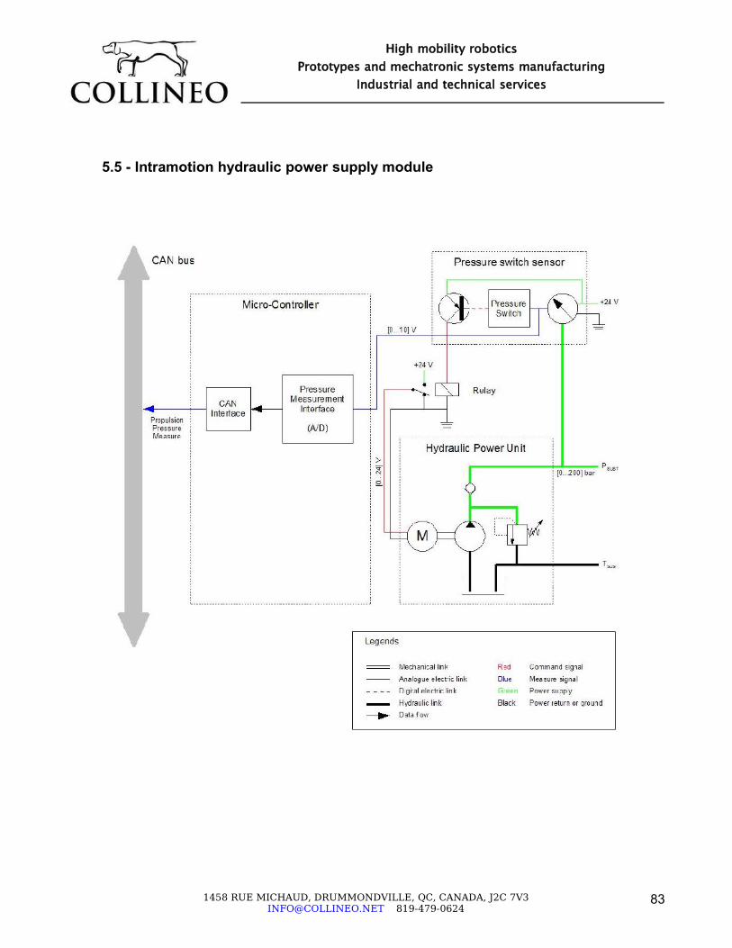
5.5 - Intramotion hydraulic power supply module
1458 RUE MICHAUD, DRUMMONDVILLE, QC, CANADA, J2C [email protected] 819-479-0624
83
High mobility roboticsPrototypes and mechatronic systems manufacturing
Industrial and technical services

6 - SAFETY CONSIDERATIONS
6.1 - Handling
The toolkit is a heavy piece of equipment. It weights 350 lbs. Moving it when it is not powered will require some assistance of mechanical needs. We do not recommend for individuals or even in teams of many, moving it. If however there would be some needs to even just push it around, always make sure you are assisted and be careful to avoid back injuries during handling.
6.2 - Heavy objects fall
When the toolkit is standing in upright position, it may fall on the side due to unpredictable behaviour. Because of its large weight it can cause severe injuries to people standing next to it.
1458 RUE MICHAUD, DRUMMONDVILLE, QC, CANADA, J2C [email protected] 819-479-0624
84
High mobility roboticsPrototypes and mechatronic systems manufacturing
Industrial and technical services
Danger when falling

6.3 - Subsystems in operation
6.3.1 - Electrical shock
Even if this is a minor threat, be careful of keeping the electrical connections covered and isolated at all times to prevent contact with hands or body.
6.3.2 - Hydraulic pressure leakage cuts
This event is rare, but if there is a hole or puncture in a hydraulic hose, the pressurized fluid is acting like a very powerful fluid cutter jet. ANY PROBLEMS YOU SEE CONCERNING ANY LEAK, Stop the toolkit and activate the EMERGENCY KILL SWITCH before doing any further investigation.
6.3.3 - Burns due to motor heat
The pump's motor can get very hot. It is a short duty cycle motor that can't dissipate it's heat fast. Be careful careful of NOT TOUCHING it until 30-40 minutes AFTER every operation.
1458 RUE MICHAUD, DRUMMONDVILLE, QC, CANADA, J2C [email protected] 819-479-0624
85
High mobility roboticsPrototypes and mechatronic systems manufacturing
Industrial and technical services
Pump motor – Can get VERY HOT

6.4 - Vehicle in motion
6.4.1 - Body part cut
The toolkit has many degrees of freedom and many moving parts. Furthermore, its eight hydraulic actuators are VERY POWERFULL. When working around the toolkit, make sure the EMERGENCY KILL SWITCH is activated and POWER is off at all times. A suddenly moving leg can easily cut a complete hand or a finger if they are trapped between the leg and the toolkit's body.
1458 RUE MICHAUD, DRUMMONDVILLE, QC, CANADA, J2C [email protected] 819-479-0624
86
High mobility roboticsPrototypes and mechatronic systems manufacturing
Industrial and technical services
POWER SWITCH
EMMERGENCY KILL SWITCH

6.4.2 - Security area
As with all moving vehicles, precautions must be observed when working around it. Maintain a minimum security radius of 3 meters around the robot where NO ONE can move into when the toolkit is in operation.
6.4.3 - External power supply limitations (portable recharge system)
When operating on the external power unit, a cable is plugged into the toolkit. If the cable is extended to it's lengths limits, the cable itself can become stretched or twisted around a foot or a leg and become dangerous for the peoples around it.
6.4.4 - Toolkit's legs stepping on operator's foot
The toolkit can actually “walk” with it's legs and can also roll aver foots. Be careful to wear STEEL CAPPED shoes at all times when working around the toolkit to prevent foot injuries.
1458 RUE MICHAUD, DRUMMONDVILLE, QC, CANADA, J2C [email protected] 819-479-0624
87
High mobility roboticsPrototypes and mechatronic systems manufacturing
Industrial and technical services

7 - BASIC REPAIR AND MAINTENANCE
The toolkit has been designed so minimal maintenance and repair need to be performed by the final user. If one of the parts gets damaged, it is strongly recommended to send the material back to Collineo for repair or adjustment.
7.1 - Periodical maintenance
7.1.1 - Mechanical systems
Harmonic drive in traction modules➢ First maintenance : change oil bath once after 100 hours of operation (after initial
wearing out).➢ Next maintenance : change oil bath every 6 months of use.
Contact manufacturer for oil specifications.
7.1.2 - Hydraulic system
Hydraulic system➢ Change oil every 6 months of use.
➢ First oil flush (after pumps and motors wear out)
➢ Change hydraulic filters every time oil is changed
Contact manufacturer for oil specifications.
7.1.3 - Electrical systems
Electric batteriesIt is expected that battery performance drops after a period of use, depending on its usage. After 300 hours of operation, batteries should be replaced or if significant performance drop is noticed.
Electric fusesCheck fuses every 6 months and replace if necessary.
1458 RUE MICHAUD, DRUMMONDVILLE, QC, CANADA, J2C [email protected] 819-479-0624
88
High mobility roboticsPrototypes and mechatronic systems manufacturing
Industrial and technical services

7.2 - Maintenance log
We strongly recommend maintaining a comprehensive SINGLE record of EVERY MAINTAINANCE AND INSPECTION executed on the toolkit. The record should mention the date of the event, the name of the person performing it, and a detailed list of the work performed.
This log will eventually serve as an important information source for generating data on the toolkit's reliability and individual component's life analysis.
7.3 - Troubleshooting
Any problem that is not a maintenance issue should be reported immediately to Collineo for appropriate actions and recommendations.
1458 RUE MICHAUD, DRUMMONDVILLE, QC, CANADA, J2C [email protected] 819-479-0624
89
High mobility roboticsPrototypes and mechatronic systems manufacturing
Industrial and technical services

8 - OPERATION IN OUTDOOR ENVIRONMENT
8.1 - Preparation before external use
8.1.1 - Levels and status (Priority 1) – Every mission departure
✔ Battery charge check. Make sure batteries are charged at least 80% of capacity before every mission.
✔ When using Li-ion batteries, drain batteries before charging them, or use Valence's battery regulation system
✔ Oil levels - Fill oil levels if required following each mission to make sure the machine is always ready for the next mission
✔ Tire pressure – Maintain pressure stated on tire by tire manufacturer
8.1.2 - Physical damage (Priority 2) – Every 5 missions
Visual inspection of the toolkit subsystems :✔ Container leakage. Check all oil tanks for external leaks, especially around the tank's
connecting side to the hydraulic power unit manifold✔ Battery container leakage
✔ Hydraulic hoses fittings leakage
✔ Watertight protection for enclosures
– Propulsion module rear covers. These covers protect the internal parts of the wheel drives. Make sure the rubber seal and cover plate are in good condition in order to ensure proper sealing.NOTE : The wheel hub covers are usually not installed during development periods, since access to parts inside the wheel hub is necessary for modules assembly. However, when a suitable assembly combination has been achieved, the wheel hub covers should be installed before operating outside.
– Direction module motor enclosure. Check if the motor housing on the steering module is not damaged as it can lead to dust or water infiltration.
✔ Mechanical seals. Check all wheel drives and articulation modules for external leakages– Propulsion module wheel seals (4 sets)
– Direction module bearing seals (2 sets)
– Wires passage connectors (cable grips) – Check they are properly tightened
✔ Oil level plugs on propulsion module gearbox (2 per wheel). Contact manufacturer for oil specifications.
1458 RUE MICHAUD, DRUMMONDVILLE, QC, CANADA, J2C [email protected] 819-479-0624
90
High mobility roboticsPrototypes and mechatronic systems manufacturing
Industrial and technical services

✔ Cables abrasion and cuts. Check all electric cables and hydraulic hoses for cuts, pinching marks and abrasions because they can lead to the toolkit's malfunction and leaks.
8.1.3 - Assembly integrity (Priority 3) – Every 6 months
✔ Check structures bolting
– Missing bolts and nuts
– Wrong bolting (if repaired or maintained by third party)
✔ Check for clinging noises
– Loose nuts
– Cracks in frames
✔ Check for structures permanent deformation and cracks in each welding beam
✔ Electric wiring and battery connections
✔ Corrosion marks
1458 RUE MICHAUD, DRUMMONDVILLE, QC, CANADA, J2C [email protected] 819-479-0624
91
High mobility roboticsPrototypes and mechatronic systems manufacturing
Industrial and technical services

8.2 - Toolkit environmental conditions
Operating temperature : - 20°C to 35°C (needs warm-up sequence at -20°C)Storage temperature : - 40°C to 50°CImpacts : 2 km/h impact on wheel drives
All hydraulic connections are industrial standards design to fully withstand dust and rain when properly closed and tightened.Legs components of the toolkit can resists light rain mist and minimal dust. Top modules of the toolkit must be protected for more demanding external uses.Propulsion and direction modules can be immersed separately in 20 cm of water, when the covers and seals are properly installed in place and well bolted. The articulation modules, however, are only IP67 protected (cannot be immersed).
1458 RUE MICHAUD, DRUMMONDVILLE, QC, CANADA, J2C [email protected] 819-479-0624
92
High mobility roboticsPrototypes and mechatronic systems manufacturing
Industrial and technical services

8.3 - Environment protection
8.3.1 - Procedures
When oil spill happens, contact your environment representative to asses the contamination. Basically, all external operations involving repair of hydraulics or even accident spillages should have the contamination spot identified, marked and the contaminated soil removed.
8.3.2 - Oil selection
The toolkit is provided with standard mineral oil. This oil is suitable for in house testing and outside operations. However, we recommend a biodegradable oil for more extensive operational use of the toolkit.
8.3.3 - Battery fluids
The toolkit is provided with common Gel-Acid batteries. However, we recommend upgrading batteries to Li-ion batteries for more extensive operational use of the toolkit. Both battery types should be treated with care and any battery damage resulting in fluid spillage should be responded with appropriate environmental cleaning measures.
1458 RUE MICHAUD, DRUMMONDVILLE, QC, CANADA, J2C [email protected] 819-479-0624
93
High mobility roboticsPrototypes and mechatronic systems manufacturing
Industrial and technical services

9 - ANNEXES
1458 RUE MICHAUD, DRUMMONDVILLE, QC, CANADA, J2C [email protected] 819-479-0624
94
High mobility roboticsPrototypes and mechatronic systems manufacturing
Industrial and technical services

TOOLKIT CANOPEN NETWORK DESCRIPTION FILE (prototype processing node only)
<?xml version="1.0" encoding="UTF-8"?><cxl version="1.00" author="COLLINEO" date="19-Mar-2006"> <objectdictionary> <entry> <index>0x6000</index> <name>Application Configuration Parameters</name> <subentry>
<subindex>0x01</subindex> <name>Update configuration flag</name> <type>BOOLEAN</type>
</subentry> <subentry>
<subindex>0x02</subindex> <name>Save configuration flag</name> <type>BOOLEAN</type>
</subentry> <subentry>
<subindex>0x03</subindex> <name>Reset configuration flag</name> <type>BOOLEAN</type>
</subentry> <subentry>
<subindex>0x04</subindex> <name>Verbose configuration flag</name> <type>BOOLEAN</type>
</subentry> </entry> <entry> <index>0x6100</index> <name>Articulation 1 Measurement Variables (TPDO1)</name> <subentry>
<subindex>0x01</subindex> <name>Measured position</name> <type>INTEGER16</type>
</subentry> <subentry>
<subindex>0x02</subindex>
<name>Measured velocity</name> <type>INTEGER16</type>
</subentry> <subentry>
<subindex>0x03</subindex> <name>Position error</name> <type>INTEGER16</type>
</subentry> <subentry>
<subindex>0x04</subindex> <name>Actuator command</name> <type>INTEGER16</type>
</subentry> </entry> <entry> <index>0x6200</index> <name>Articulation 1 Control Variables (RPDO1)</name> <subentry>
<subindex>0x01</subindex> <name>Desired position</name> <type>INTEGER16</type> </subentry>
<subentry> <subindex>0x02</subindex> <name>Reserved</name> <type>UNSIGNED8</type>
</subentry> </entry> <entry> <index>0x6101</index> <name>Articulation 2 Measurement Variables (TPDO2)</name> <subentry>
<subindex>0x01</subindex> <name>Measured position</name> <type>INTEGER16</type>
</subentry> <subentry>
<subindex>0x02</subindex>
1458 RUE MICHAUD, DRUMMONDVILLE, QC, CANADA, J2C [email protected] 819-479-0624
95
High mobility roboticsPrototypes and mechatronic systems manufacturing
Industrial and technical services

<name>Measured velocity</name> <type>INTEGER16</type>
</subentry> <subentry>
<subindex>0x03</subindex> <name>Position error</name> <type>INTEGER16</type>
</subentry> <subentry>
<subindex>0x04</subindex> <name>Actuator command</name> <type>INTEGER16</type>
</subentry> </entry> <entry> <index>0x6201</index> <name>Articulation 2 Control Variables (RPDO2)</name> <subentry>
<subindex>0x01</subindex> <name>Desired position</name> <type>INTEGER16</type> </subentry>
<subentry> <subindex>0x02</subindex> <name>Reserved</name> <type>UNSIGNED8</type>
</subentry> </entry> <entry> <index>0x6102</index> <name>Direction Measurement Variables (TPDO3)</name> <subentry>
<subindex>0x01</subindex> <name>Measured position</name> <type>INTEGER16</type>
</subentry> <subentry>
<subindex>0x02</subindex> <name>Measured velocity</name> <type>INTEGER16</type>
</subentry> <subentry>
<subindex>0x03</subindex> <name>Position error</name> <type>INTEGER16</type>
</subentry> <subentry>
<subindex>0x04</subindex> <name>Actuator command</name> <type>INTEGER16</type>
</subentry> </entry> <entry> <index>0x6202</index> <name>Direction Control Variables (RPDO3)</name> <subentry>
<subindex>0x01</subindex> <name>Desired position</name> <type>INTEGER16</type> </subentry>
<subentry> <subindex>0x02</subindex> <name>Reserved</name> <type>UNSIGNED8</type>
</subentry> </entry> <entry> <index>0x6103</index> <name>Wheel Measurement Variables (TPDO4)</name> <subentry>
<subindex>0x01</subindex> <name>Measured displacement</name> <type>INTEGER16</type>
</subentry> <subentry>
<subindex>0x02</subindex> <name>Measured velocity</name> <type>INTEGER16</type>
</subentry> <subentry>
<subindex>0x03</subindex> <name>Velocity error</name> <type>INTEGER16</type>
</subentry>
1458 RUE MICHAUD, DRUMMONDVILLE, QC, CANADA, J2C [email protected] 819-479-0624
96
High mobility roboticsPrototypes and mechatronic systems manufacturing
Industrial and technical services

<subentry> <subindex>0x04</subindex> <name>Actuator command</name> <type>INTEGER16</type>
</subentry> </entry> <entry> <index>0x6203</index> <name>Wheel Control Variables (RPDO4)</name> <subentry>
<subindex>0x01</subindex> <name>Desired velocity</name> <type>INTEGER16</type> </subentry>
<subentry> <subindex>0x02</subindex> <name>Reserved</name> <type>UNSIGNED8</type>
</subentry> </entry> <entry> <index>0x6300</index> <name>Articulation 1 Sensor Configuration Parameters</name> <subentry>
<subindex>0x01</subindex> <name>Resolution</name> <type>REAL32</type>
</subentry> <subentry>
<subindex>0x02</subindex> <name>Offset</name> <type>REAL32</type>
</subentry> </entry> <entry> <index>0x6400</index> <name>Articulation 1 Command Configuration Parameters</name> <subentry>
<subindex>0x01</subindex> <name>Deadband</name>
<type>UNSIGNED8</type> </subentry> <subentry>
<subindex>0x02</subindex> <name>Change direction</name> <type>BOOLEAN</type>
</subentry> <subentry>
<subindex>0x03</subindex> <name>Absolute maximum value</name> <type>REAL32</type>
</subentry> </entry> <entry> <index>0x6500</index> <name>Articulation 1 PID Configuration Parameters</name> <subentry>
<subindex>0x01</subindex> <name>Feed-Forward gain</name> <type>REAL32</type>
</subentry> <subentry>
<subindex>0x02</subindex> <name>Proportionnal gain</name> <type>REAL32</type>
</subentry> <subentry>
<subindex>0x03</subindex> <name>Integral gain</name> <type>REAL32</type>
</subentry> <subentry>
<subindex>0x04</subindex> <name>Derivative gain</name> <type>REAL32</type>
</subentry> <subentry>
<subindex>0x05</subindex> <name>Minimum command</name> <type>REAL32</type>
</subentry> <subentry>
<subindex>0x06</subindex>
1458 RUE MICHAUD, DRUMMONDVILLE, QC, CANADA, J2C [email protected] 819-479-0624
97
High mobility roboticsPrototypes and mechatronic systems manufacturing
Industrial and technical services

<name>Maximum command</name> <type>REAL32</type>
</subentry> </entry> <entry> <index>0x6600</index> <name>Articulation 1 PDO Scaling Factors</name> <subentry>
<subindex>0x01</subindex> <name>Measured position scaling factor</name> <type>REAL32</type>
</subentry> <subentry>
<subindex>0x02</subindex> <name>Measured velocity scaling factor</name> <type>REAL32</type>
</subentry> <subentry>
<subindex>0x03</subindex> <name>Position error scaling factor</name> <type>REAL32</type>
</subentry> <subentry>
<subindex>0x04</subindex> <name>Actuator command scaling factor</name> <type>REAL32</type>
</subentry> <subentry>
<subindex>0x05</subindex> <name>Desired position scaling factor</name> <type>REAL32</type>
</subentry> </entry> <entry> <index>0x6301</index> <name>Articulation 2 Sensor Configuration Parameters</name> <subentry>
<subindex>0x01</subindex> <name>Resolution</name> <type>REAL32</type>
</subentry> <subentry>
<subindex>0x02</subindex> <name>Offset</name> <type>REAL32</type>
</subentry> </entry> <entry> <index>0x6401</index> <name>Articulation 2 Command Configuration Parameters</name> <subentry>
<subindex>0x01</subindex> <name>Deadband</name> <type>UNSIGNED8</type>
</subentry> <subentry>
<subindex>0x02</subindex> <name>Change direction</name> <type>BOOLEAN</type>
</subentry> <subentry>
<subindex>0x03</subindex> <name>Absolute maximum value</name> <type>REAL32</type>
</subentry> </entry> <entry> <index>0x6501</index> <name>Articulation 2 PID Configuration Parameters</name> <subentry>
<subindex>0x01</subindex> <name>Feed-Forward gain</name> <type>REAL32</type>
</subentry> <subentry>
<subindex>0x02</subindex> <name>Proportionnal gain</name> <type>REAL32</type>
</subentry> <subentry>
<subindex>0x03</subindex> <name>Integral gain</name> <type>REAL32</type>
</subentry> <subentry>
1458 RUE MICHAUD, DRUMMONDVILLE, QC, CANADA, J2C [email protected] 819-479-0624
98
High mobility roboticsPrototypes and mechatronic systems manufacturing
Industrial and technical services
<subindex>0x04</subindex> <name>Derivative gain</name> <type>REAL32</type>
</subentry> <subentry>
<subindex>0x05</subindex> <name>Minimum command</name> <type>REAL32</type>
</subentry> <subentry>
<subindex>0x06</subindex> <name>Maximum command</name> <type>REAL32</type>
</subentry> </entry> <entry> <index>0x6601</index> <name>Articulation 2 PDO Scaling Factors</name> <subentry>
<subindex>0x01</subindex> <name>Measured position scaling factor</name> <type>REAL32</type>
</subentry> <subentry>
<subindex>0x02</subindex> <name>Measured velocity scaling factor</name> <type>REAL32</type>
</subentry> <subentry>
<subindex>0x03</subindex> <name>Position error scaling factor</name> <type>REAL32</type>
</subentry> <subentry>
<subindex>0x04</subindex> <name>Actuator command scaling factor</name> <type>REAL32</type>
</subentry> <subentry>
<subindex>0x05</subindex> <name>Desired position scaling factor</name> <type>REAL32</type>
</subentry>
</entry> <entry> <index>0x6302</index> <name>Direction Sensor Configuration Parameters</name> <subentry>
<subindex>0x01</subindex> <name>Resolution</name> <type>REAL32</type>
</subentry> <subentry>
<subindex>0x02</subindex> <name>Offset</name> <type>REAL32</type>
</subentry> </entry> <entry> <index>0x6402</index> <name>Direction Command Configuration Parameters</name> <subentry>
<subindex>0x01</subindex> <name>Deadband</name> <type>UNSIGNED8</type>
</subentry> <subentry>
<subindex>0x02</subindex> <name>Change direction</name> <type>BOOLEAN</type>
</subentry> <subentry>
<subindex>0x03</subindex> <name>Absolute maximum value</name> <type>REAL32</type>
</subentry> </entry> <entry> <index>0x6502</index> <name>Direction PID Configuration Parameters</name> <subentry>
<subindex>0x01</subindex> <name>Feed-Forward gain</name> <type>REAL32</type>
</subentry>
1458 RUE MICHAUD, DRUMMONDVILLE, QC, CANADA, J2C [email protected] 819-479-0624
99
High mobility roboticsPrototypes and mechatronic systems manufacturing
Industrial and technical services

<subentry> <subindex>0x02</subindex> <name>Proportionnal gain</name> <type>REAL32</type>
</subentry> <subentry>
<subindex>0x03</subindex> <name>Integral gain</name> <type>REAL32</type>
</subentry> <subentry>
<subindex>0x04</subindex> <name>Derivative gain</name> <type>REAL32</type>
</subentry> <subentry>
<subindex>0x05</subindex> <name>Minimum command</name> <type>REAL32</type>
</subentry> <subentry>
<subindex>0x06</subindex> <name>Maximum command</name> <type>REAL32</type>
</subentry> </entry> <entry> <index>0x6602</index> <name>Direction PDO Scaling Factors</name> <subentry>
<subindex>0x01</subindex> <name>Measured position scaling factor</name> <type>REAL32</type>
</subentry> <subentry>
<subindex>0x02</subindex> <name>Measured velocity scaling factor</name> <type>REAL32</type>
</subentry> <subentry>
<subindex>0x03</subindex> <name>Position error scaling factor</name> <type>REAL32</type>
</subentry> <subentry>
<subindex>0x04</subindex> <name>Actuator command scaling factor</name> <type>REAL32</type>
</subentry> <subentry>
<subindex>0x05</subindex> <name>Desired position scaling factor</name> <type>REAL32</type>
</subentry> </entry> <entry> <index>0x6303</index> <name>Wheel Sensor Configuration Parameters</name> <subentry>
<subindex>0x01</subindex> <name>Displacement resolution</name> <type>REAL32</type>
</subentry> <subentry>
<subindex>0x02</subindex> <name>Change direction</name> <type>BOOLEAN</type>
</subentry> </entry> <entry> <index>0x6403</index> <name>Wheel Command Configuration Parameters</name> <subentry>
<subindex>0x01</subindex> <name>Deadband</name> <type>UNSIGNED8</type>
</subentry> <subentry>
<subindex>0x02</subindex> <name>Change direction</name> <type>BOOLEAN</type>
</subentry> <subentry>
<subindex>0x03</subindex> <name>Absolute maximum value</name>
1458 RUE MICHAUD, DRUMMONDVILLE, QC, CANADA, J2C [email protected] 819-479-0624
100
High mobility roboticsPrototypes and mechatronic systems manufacturing
Industrial and technical services

<type>REAL32</type> </subentry> </entry> <entry> <index>0x6503</index> <name>Wheel PID Configuration Parameters</name> <subentry>
<subindex>0x01</subindex> <name>Feed-Forward gain</name> <type>REAL32</type>
</subentry> <subentry>
<subindex>0x02</subindex> <name>Proportionnal gain</name> <type>REAL32</type>
</subentry> <subentry>
<subindex>0x03</subindex> <name>Integral gain</name> <type>REAL32</type>
</subentry> <subentry>
<subindex>0x04</subindex> <name>Derivative gain</name> <type>REAL32</type>
</subentry> <subentry>
<subindex>0x05</subindex> <name>Minimum command</name> <type>REAL32</type>
</subentry> <subentry>
<subindex>0x06</subindex> <name>Maximum command</name> <type>REAL32</type>
</subentry> </entry> <entry> <index>0x6603</index> <name>Wheel PDO Scaling Factors</name> <subentry>
<subindex>0x01</subindex> <name>Measured displacement scaling factor</name>
<type>REAL32</type> </subentry> <subentry>
<subindex>0x02</subindex> <name>Measured velocity scaling factor</name> <type>REAL32</type>
</subentry> <subentry>
<subindex>0x03</subindex> <name>Velocity error scaling factor</name> <type>REAL32</type>
</subentry> <subentry>
<subindex>0x04</subindex> <name>Actuator command scaling factor</name> <type>REAL32</type>
</subentry> <subentry>
<subindex>0x05</subindex> <name>Desired velocity scaling factor</name> <type>REAL32</type>
</subentry> </entry> </objectdictionary> <processdata>
<data> <name>Articulation 1 measured position</name> <id>0x188</id> <startbit>0</startbit> <endbit>15</endbit> <type>INTEGER16</type> <units>deg</units>
</data> <data>
<name>Articulation 1 measured velocity</name> <id>0x188</id> <startbit>16</startbit> <endbit>31</endbit> <type>INTEGER16</type> <units>deg/s</units>
</data>
1458 RUE MICHAUD, DRUMMONDVILLE, QC, CANADA, J2C [email protected] 819-479-0624
101
High mobility roboticsPrototypes and mechatronic systems manufacturing
Industrial and technical services

<data> <name>Articulation 1 position error</name> <id>0x188</id> <startbit>32</startbit> <endbit>47</endbit> <type>INTEGER16</type> <units>deg</units>
</data> <data>
<name>Articulation 1 actuator command</name> <id>0x188</id> <startbit>48</startbit> <endbit>63</endbit> <type>INTEGER16</type> <units>%</units>
</data> <data>
<name>Articulation 2 measured position</name> <id>0x288</id> <startbit>0</startbit> <endbit>15</endbit> <type>INTEGER16</type> <units>deg</units>
</data> <data>
<name>Articulation 2 measured velocity</name> <id>0x288</id> <startbit>16</startbit> <endbit>31</endbit> <type>INTEGER16</type> <units>deg/s</units>
</data> <data>
<name>Articulation 2 position error</name> <id>0x288</id> <startbit>32</startbit> <endbit>47</endbit> <type>INTEGER16</type> <units>deg</units>
</data> <data>
<name>Articulation 2 actuator command</name>
<id>0x288</id> <startbit>48</startbit> <endbit>63</endbit> <type>INTEGER16</type> <units>%</units>
</data> <data>
<name>Direction measured position</name> <id>0x388</id> <startbit>0</startbit> <endbit>15</endbit> <type>INTEGER16</type> <units>deg</units>
</data> <data>
<name>Direction measured velocity</name> <id>0x388</id> <startbit>16</startbit> <endbit>31</endbit> <type>INTEGER16</type> <units>deg/s</units>
</data> <data>
<name>Direction position error</name> <id>0x388</id> <startbit>32</startbit> <endbit>47</endbit> <type>INTEGER16</type> <units>deg</units>
</data> <data>
<name>Direction actuator command</name> <id>0x388</id> <startbit>48</startbit> <endbit>63</endbit> <type>INTEGER16</type> <units>%</units>
</data> <data>
<name>Wheel measured displacement</name> <id>0x488</id>
1458 RUE MICHAUD, DRUMMONDVILLE, QC, CANADA, J2C [email protected] 819-479-0624
102
High mobility roboticsPrototypes and mechatronic systems manufacturing
Industrial and technical services
<startbit>0</startbit> <endbit>15</endbit> <type>INTEGER16</type> <units>rev</units>
</data> <data>
<name>Wheel measured velocity</name> <id>0x488</id> <startbit>16</startbit> <endbit>31</endbit> <type>INTEGER16</type> <units>rpm</units>
</data> <data>
<name>Wheel velocity error</name> <id>0x488</id> <startbit>32</startbit> <endbit>47</endbit> <type>INTEGER16</type> <units>rpm</units>
</data> <data>
<name>Wheel actuator command</name> <id>0x488</id> <startbit>48</startbit> <endbit>63</endbit> <type>INTEGER16</type> <units>%</units>
</data> </processdata></cxl>
1458 RUE MICHAUD, DRUMMONDVILLE, QC, CANADA, J2C [email protected] 819-479-0624
103
High mobility roboticsPrototypes and mechatronic systems manufacturing
Industrial and technical services

TOOLKIT MAIN ELECTRICAL SYSTEM
1458 RUE MICHAUD, DRUMMONDVILLE, QC, CANADA, J2C [email protected] 819-479-0624
104
High mobility roboticsPrototypes and mechatronic systems manufacturing
Industrial and technical services

TOOLKIT ELECTRICAL POWER SUPPLY REGULATION MODULE
1458 RUE MICHAUD, DRUMMONDVILLE, QC, CANADA, J2C [email protected] 819-479-0624
105
High mobility roboticsPrototypes and mechatronic systems manufacturing
Industrial and technical services

HPI HYDRAULIC POWER UNIT PERFORMANCE CURVES
1458 RUE MICHAUD, DRUMMONDVILLE, QC, CANADA, J2C [email protected] 819-479-0624
106
High mobility roboticsPrototypes and mechatronic systems manufacturing
Industrial and technical services

HPI HYDRAULIC POWER UNIT PERFORMANCE TABLES
1458 RUE MICHAUD, DRUMMONDVILLE, QC, CANADA, J2C [email protected] 819-479-0624
107
High mobility roboticsPrototypes and mechatronic systems manufacturing
Industrial and technical services


UNCLASSIFIED SECURITY CLASSIFICATION OF FORM (highest classification of Title, Abstract, Keywords)
DOCUMENT CONTROL DATA (Security classification of title, body of abstract and indexing annotation must be entered when the overall document is classified)
1. ORIGINATOR (the name and address of the organization preparing the document. Organizations for who the document was prepared, e.g. Establishment sponsoring a contractor's report, or tasking agency, are entered in Section 8.)
Collineo inc. 1375 rue Gay-Lussac, bureau A Boucherville QC J4B 7K1
2. SECURITY CLASSIFICATION (overall security classification of the document, including special
warning terms if applicable)
Unclassified
3. TITLE (the complete document title as indicated on the title page. Its classification should be indicated by the appropriate abbreviation (S, C or U) in parentheses after the title).
Micro-Hydraulic Toolkit Report
4. AUTHORS (Last name, first name, middle initial. If military, show rank, e.g. Doe, Maj. John E.)
Lambert, Guillaume
5. DATE OF PUBLICATION (month and year of publication of document)
December 2006
6a. NO. OF PAGES (total containing information, include Annexes, Appendices, etc) 107
6b. NO. OF REFS (total cited in document)
0
7. DESCRIPTIVE NOTES (the category of the document, e.g. technical report, technical note or memorandum. If appropriate, enter the type of report, e.g. interim, progress, summary, annual or final. Give the inclusive dates when a specific reporting period is covered.)
Final Report for the Micro-hydraulic Toolkit Platform
8. SPONSORING ACTIVITY (the name of the department project office or laboratory sponsoring the research and development. Include the address.)
Defence R&D Canada – Suffield, PO Box 4000, Station Main, Medicine Hat, AB T1A 8K6
9a. PROJECT OR GRANT NO. (If appropriate, the applicable research and development project or grant number under which the document was written. Please specify whether project or grant.)
9b. CONTRACT NO. (If appropriate, the applicable number under which the document was written.)
W7702-03R975
10a. ORIGINATOR'S DOCUMENT NUMBER (the official document number by which the document is identified by the originating activity. This number must be unique to this document.)
DRDC Suffield CR 2008-212
10b. OTHER DOCUMENT NOs. (Any other numbers which may be assigned this document either by the originator or by the sponsor.)
11. DOCUMENT AVAILABILITY (any limitations on further dissemination of the document, other than those imposed by security classification)
( x ) Unlimited distribution ( ) Distribution limited to defence departments and defence contractors; further distribution only as approved ( ) Distribution limited to defence departments and Canadian defence contractors; further distribution only as approved ( ) Distribution limited to government departments and agencies; further distribution only as approved ( ) Distribution limited to defence departments; further distribution only as approved ( ) Other (please specify):
12. DOCUMENT ANNOUNCEMENT (any limitation to the bibliographic announcement of this document. This will normally corresponded to the Document Availability (11). However, where further distribution (beyond the audience specified in 11) is possible, a wider announcement audience may be selected).
Unlimited UNCLASSIFIED SECURITY CLASSIFICATION OF FORM
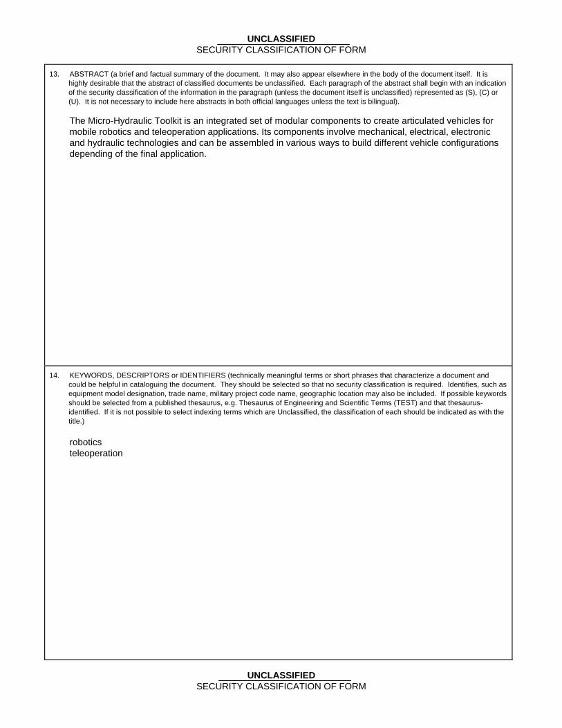
UNCLASSIFIED SECURITY CLASSIFICATION OF FORM
13. ABSTRACT (a brief and factual summary of the document. It may also appear elsewhere in the body of the document itself. It is highly desirable that the abstract of classified documents be unclassified. Each paragraph of the abstract shall begin with an indication of the security classification of the information in the paragraph (unless the document itself is unclassified) represented as (S), (C) or (U). It is not necessary to include here abstracts in both official languages unless the text is bilingual).
The Micro-Hydraulic Toolkit is an integrated set of modular components to create articulated vehicles for mobile robotics and teleoperation applications. Its components involve mechanical, electrical, electronic and hydraulic technologies and can be assembled in various ways to build different vehicle configurations depending of the final application.
14. KEYWORDS, DESCRIPTORS or IDENTIFIERS (technically meaningful terms or short phrases that characterize a document and could be helpful in cataloguing the document. They should be selected so that no security classification is required. Identifies, such as equipment model designation, trade name, military project code name, geographic location may also be included. If possible keywords should be selected from a published thesaurus, e.g. Thesaurus of Engineering and Scientific Terms (TEST) and that thesaurus-identified. If it is not possible to select indexing terms which are Unclassified, the classification of each should be indicated as with the title.) robotics teleoperation
UNCLASSIFIED SECURITY CLASSIFICATION OF FORM


Defence R&D Canada R & D pour la défense Canada Canada's Leader in Defence
and National Security Science and Technology
Chef de file au Canada en matière de science et de technologie pour la défense et la sécurité nationale
www.drdc-rddc.gc.ca