a micro mobile hydraulic system using electro-rheological ... · a micro mobile hydraulic system...
TRANSCRIPT
A MICRO MOBILE HYDRAULIC SYSTEM USING ELECTRO-RHEOLOGICAL FLUID
Kazuhiro YOSHIDA*, Takafumi ANZAI**, Joon-wan KIM* and Shinichi YOKOTA*
* Precision and Intelligence Laboratory ** Graduate School
Tokyo Institute of Technology R2-42, 4259 Nagatsuta-cho, Midori-ku, Yokohama, 226-8503 Japan
(E-mail: [email protected])
ABSTRACT
The paper presents a novel micro mobile hydraulic system using ERF (electro-rheological fluid) for in-pipe working micromachines, etc. The hydraulic system generates high power motion irrespective of the system posture. First, a micro rolling diaphragm actuator (MRDA) equipped with an ER valve is proposed and developed. The MRDA is a fluid power microactuator which has long stroke and large output force. The ER valve controls ERF flow by the apparent viscosity increase due to the applied electric field. Second, an FI micropump for high viscosity fluids like ERFs is developed, which generates high output fluid power utilizing fluid inertia (FI) effect in a pipe. In addition, a sealed flexible tank is developed to adapt the posture and the ERF amount changes of the tank. Finally, a micro mobile hydraulic system is constructed using the above-mentioned elements and the validity is confirmed through experiments.
KEY WORDS
Micromachine, Mobile hydraulics, ERF (electro-rheological fluid), Microactuator, Micropump
INTRODUCTION
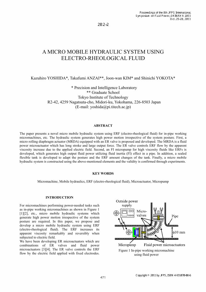
For micromachines performing power-needed tasks such as in-pipe working micromachines as shown in Figure 1 [1][2], etc., micro mobile hydraulic systems which generate high power motion irrespective of the system posture are required. In this paper, we propose and develop a micro mobile hydraulic system using ERF (electro-rheological fluid). The ERF increases its apparent viscosity remarkably and reversibly when subjected to electric field. We have been developing ER microactuators which are combinations of ER valves and fluid power microactuators [3][4]. The ER valve controls the ERF flow by the electric field applied with fixed electrodes.
Figure 1 In-pipe working micromachine using fluid power
471
The ER microactuator controls the high density fluid power [5] with simple and miniaturizable structure. As fluid power microactuators, bellows are the promising candidates, however, ratio of the extension to the free length, which is called the “extension ratio,” hereafter, of conventional metal bellows is about 20 % due to the permanent deformation and large free length is required for the sufficiently long stroke. Rubber bellows have large extension ratio, however, the allowable pressure and the output force are not so high. In this study, a micro rolling diaphragm actuator called “MRDA” is proposed, which utilizes a rolling diaphragm which can linearly extend long stroke with enclosing the working fluid. Then an MRDA equipped with an ER valve is proposed and developed, which has compact structure, large extension ratio, and large output force. As a fluid power source, an FI micropump [6] is developed for high viscosity fluids like ERFs. The FI micropump utilizes fluid inertia (FI) effect in a pipe and has realized high output fluid power in water pumping. In addition, a sealed flexible tank is developed to adapt the posture and the ERF amount changes of the tank. Finally, a micro mobile hydraulic system is constructed using the above-mentioned elements. The characteristics and the validity are investigated experimentally.
MICRO ROLLING DIAPHRAGM ACTUAOTR
(MRDA) EQUIPPED WITH ER VALVE
Proposition of MRDA equipped with ER valve There are several fluid power actuators such as piston-cylinders, diaphragms, metal bellows, rubber bellows, and rolling diaphragm-cylinders [7]. The piston-cylinders have long stroke and high output force due to high allowable pressure, however, the miniaturization needs special improvements to prevent leak and friction [8]. The diaphragms have simple structure and high output force, however, the strokes are very small for in-pipe working micromachines, etc. The metal bellows have high output force due to high
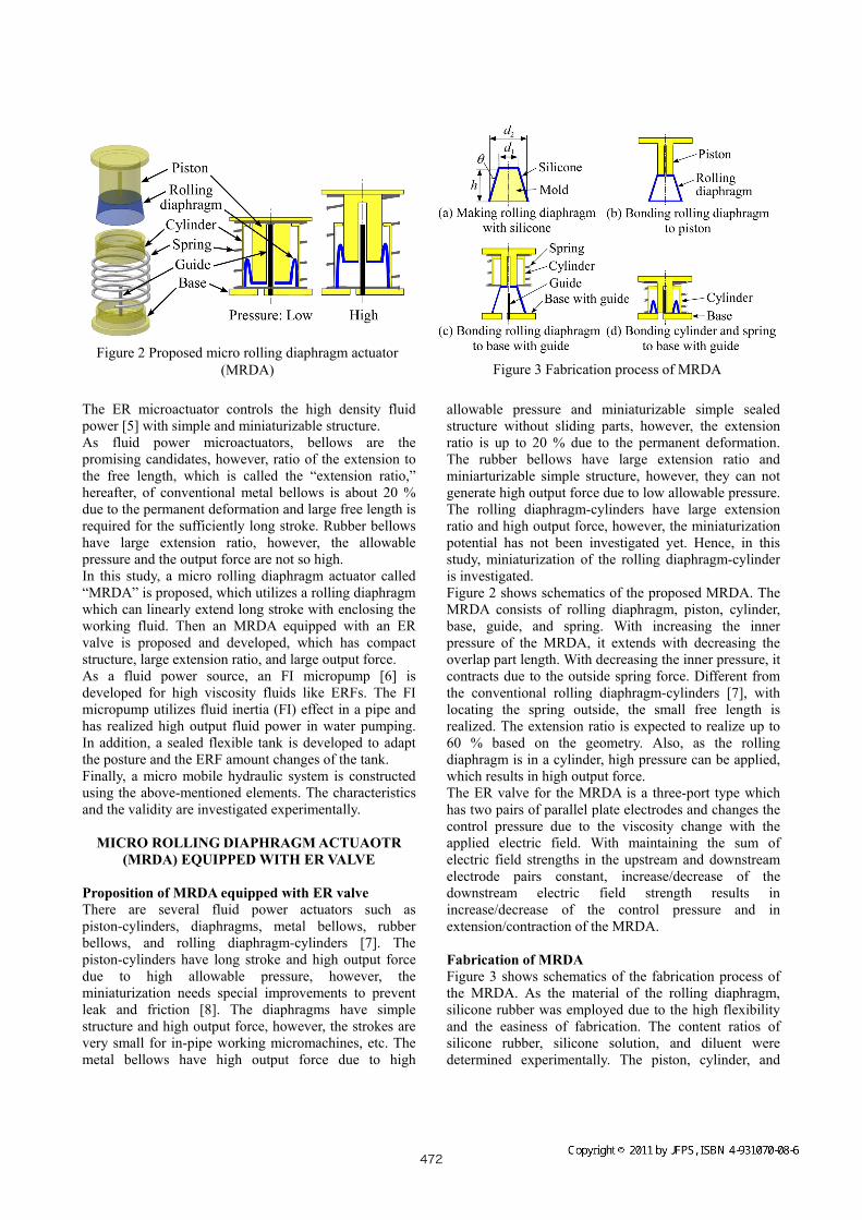
allowable pressure and miniaturizable simple sealed structure without sliding parts, however, the extension ratio is up to 20 % due to the permanent deformation. The rubber bellows have large extension ratio and miniarturizable simple structure, however, they can not generate high output force due to low allowable pressure. The rolling diaphragm-cylinders have large extension ratio and high output force, however, the miniaturization potential has not been investigated yet. Hence, in this study, miniaturization of the rolling diaphragm-cylinder is investigated. Figure 2 shows schematics of the proposed MRDA. The MRDA consists of rolling diaphragm, piston, cylinder, base, guide, and spring. With increasing the inner pressure of the MRDA, it extends with decreasing the overlap part length. With decreasing the inner pressure, it contracts due to the outside spring force. Different from the conventional rolling diaphragm-cylinders [7], with locating the spring outside, the small free length is realized. The extension ratio is expected to realize up to 60 % based on the geometry. Also, as the rolling diaphragm is in a cylinder, high pressure can be applied, which results in high output force. The ER valve for the MRDA is a three-port type which has two pairs of parallel plate electrodes and changes the control pressure due to the viscosity change with the applied electric field. With maintaining the sum of electric field strengths in the upstream and downstream electrode pairs constant, increase/decrease of the downstream electric field strength results in increase/decrease of the control pressure and in extension/contraction of the MRDA. Fabrication of MRDA Figure 3 shows schematics of the fabrication process of the MRDA. As the material of the rolling diaphragm, silicone rubber was employed due to the high flexibility and the easiness of fabrication. The content ratios of silicone rubber, silicone solution, and diluent were determined experimentally. The piston, cylinder, and
Figure 2 Proposed micro rolling diaphragm actuator (MRDA) Figure 3 Fabrication process of MRDA
472
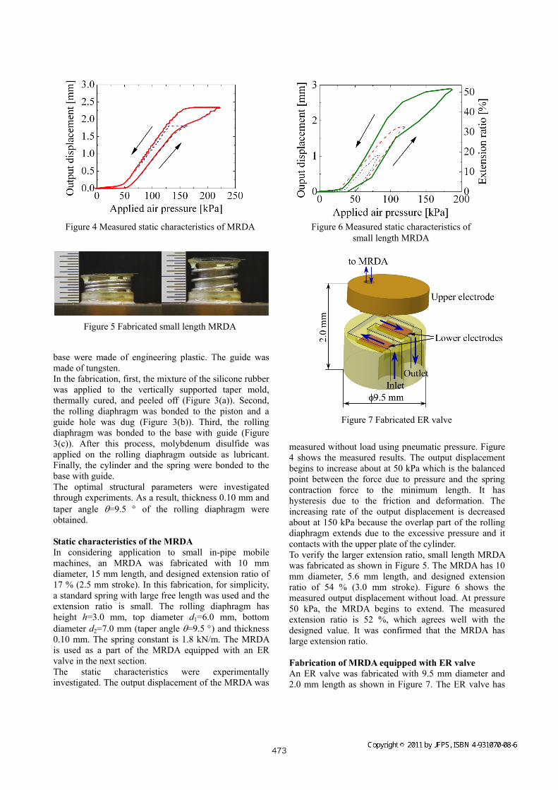
base were made of engineering plastic. The guide was made of tungsten. In the fabrication, first, the mixture of the silicone rubber was applied to the vertically supported taper mold, thermally cured, and peeled off (Figure 3(a)). Second, the rolling diaphragm was bonded to the piston and a guide hole was dug (Figure 3(b)). Third, the rolling diaphragm was bonded to the base with guide (Figure 3(c)). After this process, molybdenum disulfide was applied on the rolling diaphragm outside as lubricant. Finally, the cylinder and the spring were bonded to the base with guide. The optimal structural parameters were investigated through experiments. As a result, thickness 0.10 mm and taper angle =9.5 of the rolling diaphragm were obtained. Static characteristics of the MRDA In considering application to small in-pipe mobile machines, an MRDA was fabricated with 10 mm diameter, 15 mm length, and designed extension ratio of 17 % (2.5 mm stroke). In this fabrication, for simplicity, a standard spring with large free length was used and the extension ratio is small. The rolling diaphragm has height h=3.0 mm, top diameter d1=6.0 mm, bottom diameter d2=7.0 mm (taper angle =9.5 ) and thickness 0.10 mm. The spring constant is 1.8 kN/m. The MRDA is used as a part of the MRDA equipped with an ER valve in the next section. The static characteristics were experimentally investigated. The output displacement of the MRDA was
measured without load using pneumatic pressure. Figure 4 shows the measured results. The output displacement begins to increase about at 50 kPa which is the balanced point between the force due to pressure and the spring contraction force to the minimum length. It has hysteresis due to the friction and deformation. The increasing rate of the output displacement is decreased about at 150 kPa because the overlap part of the rolling diaphragm extends due to the excessive pressure and it contacts with the upper plate of the cylinder. To verify the larger extension ratio, small length MRDA was fabricated as shown in Figure 5. The MRDA has 10 mm diameter, 5.6 mm length, and designed extension ratio of 54 % (3.0 mm stroke). Figure 6 shows the measured output displacement without load. At pressure 50 kPa, the MRDA begins to extend. The measured extension ratio is 52 %, which agrees well with the designed value. It was confirmed that the MRDA has large extension ratio. Fabrication of MRDA equipped with ER valve An ER valve was fabricated with 9.5 mm diameter and 2.0 mm length as shown in Figure 7. The ER valve has
Figure 4 Measured static characteristics of MRDA
Figure 5 Fabricated small length MRDA
Figure 6 Measured static characteristics of small length MRDA
Figure 7 Fabricated ER valve
473

upstream and downstream flow channels, each of which has 2.5 mm width, 3.4 mm length, and 0.15 mm height that is the electrode gap length. Figure 8 shows the measured static characteristics with different supply pressures as a parameter. The ERF was a nematic liquid crystal (MLC-6457-000, Merck Ltd., Japan. Base viscosity 23 mPas at 23 C). The sum of electric field strengths in the upstream and downstream flow channels was 5 kV/mm. Based on the results, it was confirmed that there are no hystereses for every supply pressures. The control pressure range are 61, 68, and 62 kPa for supply pressures 100, 150, and 200 kPa, respectively. The control pressure range to the supply pressure decreases with increasing supply pressure, which is due to lower ER effect for higher flow velocities. An MRDA equipped with an ER valve was fabricated with 10 mm diameter and 17 mm length using the
MRDA fabricated in the previous section and the ER valve mentioned above. Figure 9 shows the measured static characteristics. As the control pressure range is almost same for the different supply pressures, the maximum output displacement is 0.9 mm at supply pressure 150 kPa at which the MRDA has linear characteristics without saturation. The output displacement has also hysteresis due to the characteristics of the MRDA.
FI MICROPUMP AND SEALED FLEXIBLE TANK
A piezoelectric micropump using fluid inertia (FI) effect in a pipe called the “FI micropump” [6] was newly developed for high viscosity fluids like ERFs. Figure 10 shows schematics of the FI micropump. The pump consists of a reciprocating pump chamber driven by a multilayered PZT actuator, an inlet check valve, and an outlet pipe with small diameter. An accumulator, which consists of a flexible tube in this study, is attached to the outlet in the actual device and the outlet pressure is constant. In the chamber above the inlet check valve, a plastic diaphragm is installed as a buffer to maintain the inlet pressure constant in the actual device. In a pumping period shown in Figure 10(a), the PZT actuator contracts the pump chamber, the inner pressure increases, the inlet check valve closes, and the working fluid flows out through the outlet pipe at a high flow velocity. In the subsequent suction period shown in Figure 10(b), the PZT actuator expands the pump chamber, the inner pressure decreases, and the working fluid flows in through the opened inlet check valve. At the same time, in the outlet pipe, the flow is going to
Figure 8 Measured static characteristics of ER valve
Figure 9 Measured static characteristics of MRDA equipped with ER valve
(a) Pumping period
(b) Suction period
Figure 10 Working principle of FI micropump
474

maintain due to the fluid inertia (FI) effect in the outlet pipe with a liquid column separation. Thus, the pump flows out the working fluid in not only the pumping but also the suction periods and realizes an outlet flow rate higher than the value estimated with the displacement. Through experiments, an output fluid power up to 0.22 W for water pumping has been realized by an FI micropump with 2.3 cm3 in volume [6]. For pumping high viscosity fluids like ERFs, a multi-reed valve was proposed as the inlet check valve. Also, the size of the outlet pipe was optimized [9]. Figure 11 shows the fabricated FI micropump with 10 mm in diameter. The volume is 1.3 cm3 which is 60 % of the previous pump [6]. Figure 12 shows the measured load characteristics of the FI micropump. The working fluid was silicone oil which had viscosity 19 mPas similar to the nematic liquid crystal used in this study. The driving voltage of the PZT actuator had 100 Vpp amplitude, 70 V offset, and
frequencies of 2.0, 2.5, amd 3.0 kHz. The maximum output fluid power of 65 mW was obtained. Furthermore, to adapt the posture and the ERF amount changes of the tank, a sealed flexible tank made of polyethylene film was fabricated with 1.5 cm3 in volume.
MICRO MOBILE HYDRAULIC SYSTEM
By integrating the MRDA equipped with an ER valve, the FI micropump, and the sealed flexible tank, a micro mobile hydraulic system was constructed as shown in Figure 13. Figure 14 shows an example of the measured step responses. The stroke 0.4 mm was successfully obtained, which shows the sealed tank system can work similar to a conventional open tank system. The rise times were 0.3 s for extension and 0.2 s for contraction.
CONCLUSIONS
In this paper, we proposed and developed a micro mobile hydraulic system using ERF which generates high power
Figure 11 Fabricated FI micropump
Figure 12 Measured load characteristics of FI micropump
Figure 13 Micro mobile hydraulic system using ERF
Figure 14 Measured output displacement of micro mobile hydraulic system
475
motion irrespective of the system posture. The main results are summarized as follows: 1) A micro rolling diaphragm actuator (MRDA) was proposed, which has compact structure, large extension ratio, and large output force. 2) An MRDA equipped with an ER valve was fabricated with 10 mm in diameter and experimentally characterized. 3) An FI micropump using fluid inertia (FI) effect in a pipe was developed with 9.5 mm in diameter for high viscosity fluids like ERFs. 4) A micro mobile hydraulic system was constructed by integrating the above-mentioned elements and the validity was confirmed experimentally.
REFERENCES
1. Takeda, M., Applications of MEMS to Industrial
Inspection, Proc. MEMS 2001, 2001, pp. 182-191. 2. Yoshida, K., Takahashi, K. and Yokota, S., An
In-Pipe Mobile Micromachine Using Fluid Power (A Mechanism Adaptable to Pipe Diameters), JSME Int. J.(Ser. B), 2000, 43-1, pp. 29-35.
3. Yoshida, K., Park, J.-H., Yano, H., Yokota, S. and Yun, S., Study of Valve-Integrated Microactuator
Using Homogeneous Electro-Rheological Fluid, Sensors and Materials, 2005, 17-3, pp. 97-112.
4. De Volder, M., Yoshida, K., Yokota, S. and Reynaerts, D., The Use of Liquid Crystals as Electrorheological Fluids in Microsystems: Model and Measurements, J. of Micromechanics and Microengineering, 2006, 16-3, pp. 612-619.
5. Yoshida, K. and Yokota, S., Study on High-Power Micro-Actuator Using Fluid Power, Preprints of the 6th Int. Conf. on Flow Measurement (FLOMEKO’93), 1993, 1, pp. 122-130.
6. Yoshida, K., Jung, Y.-O., Seto, T., Takagi, K., Park, J.-H. and Yokota, S., A Piezoelectric Micropump Using Fluid Inertia in Pipe and Its Application, Proc. 6th JFPS Int. Symp. on Fluid Power, Tsukuba 2005, 2005, pp. 688-693.
7. March Bellofram homepage: http://www.marshbellofram.com/
8. De Volder, M. and Reynaerts, D., Pneumatic and Hydraulic Microactuators: A Review, J. of Micromechanics and Microengineering, 2010, 20-4, 043001 (18pp).
9. Yoshida, K., Muto, T., Kim, J. W. and Yokota, S., An ER Microactuator with Built-in Pump and Valve, Proc. ACTUATOR 2010, 2010, pp. 556-559.
476