micro-grid droop control strategy and isolated island ... · pdf filemicro-grid droop control...
TRANSCRIPT
Micro-Grid Droop Control Strategy and Isolated Island Operation System Stability Analysis
Li-Jun Qin , Wan-Tao Yang Institute of Electrical and Electronic Engineering
North China Electric Power University North China Electric Power University, Beijing, 102206, China
China [email protected]
Abstract: -In the micro-grid, droop control strategy simulates traditional power system droop characteristics , by changing the output of active and reactive power to control the output voltage frequency and amplitude, thus the micro-grid system can work at the stabilize voltage point in island operation mode . And the voltage is more or less with the grid-connect mode,so that the transition is smooth when switching,which can guarantee the load work undisturbed. Microgrid based on droop control can achieve automatically adjust voltage and frequency, without the aid of communication, which can improve system reliability, and easy to implement micro-power and load plug and play. We designed specifically simulation circuit for the droop control strategy on PSIM . And the output waveform is studied. Simulation results show the schematic design of the control strategy is correct.We established an island microgrid complete small-signal state space model, which took into account the inverter power small-signal sub-model, network lines and the load small signal sub-model.It use eigenvalue method to analysis microgrid small signal model state matrix, to get the following conclusions: droop coefficient increases will reduce the stability of the micro-grid system; when the line impedance is smaller, micro-grid is easy to lose stability. Finally, We use the simulation tools to verify the small signal stability analysis conclusions is correct. Key-Words: - microgrid, droop control, PSIM, Simulink, converter, small signal stability analysis 1 Introduction Today's power system development has already closely integrated with modern control theory. Power grid is developing toward two distinct directions: a large capacity, long-distance, high pressure, even UHV AC and DC transmission level and a large grid interconnection; the other is small capacity and relatively independent micro-grid. For these two directions, there are still some common problems (such as the optimization of operation, coordinated scheduling and control, etc.) to be resolved. Over the past decades, power grid develops rapidly ,and now has becomed a major power transmission channel. But with the power grid scale up and the whole society deepen the dependence on electricity, the drawbacks of ultra-large-scale systems are also reflected, such as high cost, difficult to run and so on. In addition, worldwide energy supply remains tense, it is imminent to rationally develop and utilize new energy. Distributed generation with the installation location flexibility and high efficiency of energy use, can effectively solute many problems of large
centralized power grid. Therefore, distributed generation was put on the agenda. Distributed power has obvious advantages, there are also some problems, such as high-cost to access to distributed power, difficult to control. Moreover, for a large grid, distributed power source is not controllable. The system often take quarantine and restriction approachs to DG, to reduce the impact on the grid. In addition, IEEEP1547 provides DG network standard, that is, if the system fails, the distributed power must be immediately quitted running. This leads to distributed power can not be fully effectived. Scholars in order to coordinate the contradiction between DG and large grid, put forward the concept of micro-grid.
Micro grid (MG) can be combined with the loads, generators, control devices and energy storage devices into a manageable unit, with a lot of non-linear distributed power. It can not only solve the problem of large-scale distributed power access, but also bring the user and the system many benefits. Thus microgrid research is useful supplement of the existing backbone network .It is
WSEAS TRANSACTIONS on POWER SYSTEMS Li-Jun Qin , Wan-Tao Yang
E-ISSN: 2224-350X 145 Volume 10, 2015
of great significance whether for the use of new energy from the environmental point of view, or considering increasing the supply of quality and reliability of power supply from the backdrop of China's power grid interconnection . Among them, one of the key problems of the study of micro-grid is coordination and control technology and energy management systems research.
In summary, micro network converter control method study has great significance and application prospects. 2 Micro-Grid Inverter Control Micro-network (MG) has a variety of different types of distributed power (DG) and extensive power electronic devices to interconnect, resulting in the existence of a fundamental difference between micro-grid and general transmission and distribution systems; In addition, because of micro-grid system can run on-grid and can run off-grid operation mode. It need to switch. It also brings many complex control problems.That must take control methods different from the traditional methods, or make a large adjustment.
For parallel operation of DG, the main control methods are several programs such as non-contact line control based on droop, master-slave control, centralized control and decentralized logic control. Last three options need contact line to communication. In distributed generation systems, each power supply spacing stays away. The transmission signal is complex, reducing system reliability. No tie-line control scheme is that droop control based on local electrical quantities to adjusted DG . It can respond MG dynamic process in a very short period of time, to meet the requirements of real-time control. 3 Droop Control Strategy 3.1 Droop Control Method Operating Principle Droop control is in essence the voltage source inverter voltage-controlled method , by adjusting the voltage amplitude and phase to achieve control of the transmission power. In the inductive transmission line, active power mainly depends on the power angle. Reactive power depends on the voltage difference.So Power angle can be used to
control active power and voltage difference can be used to control reactive power.
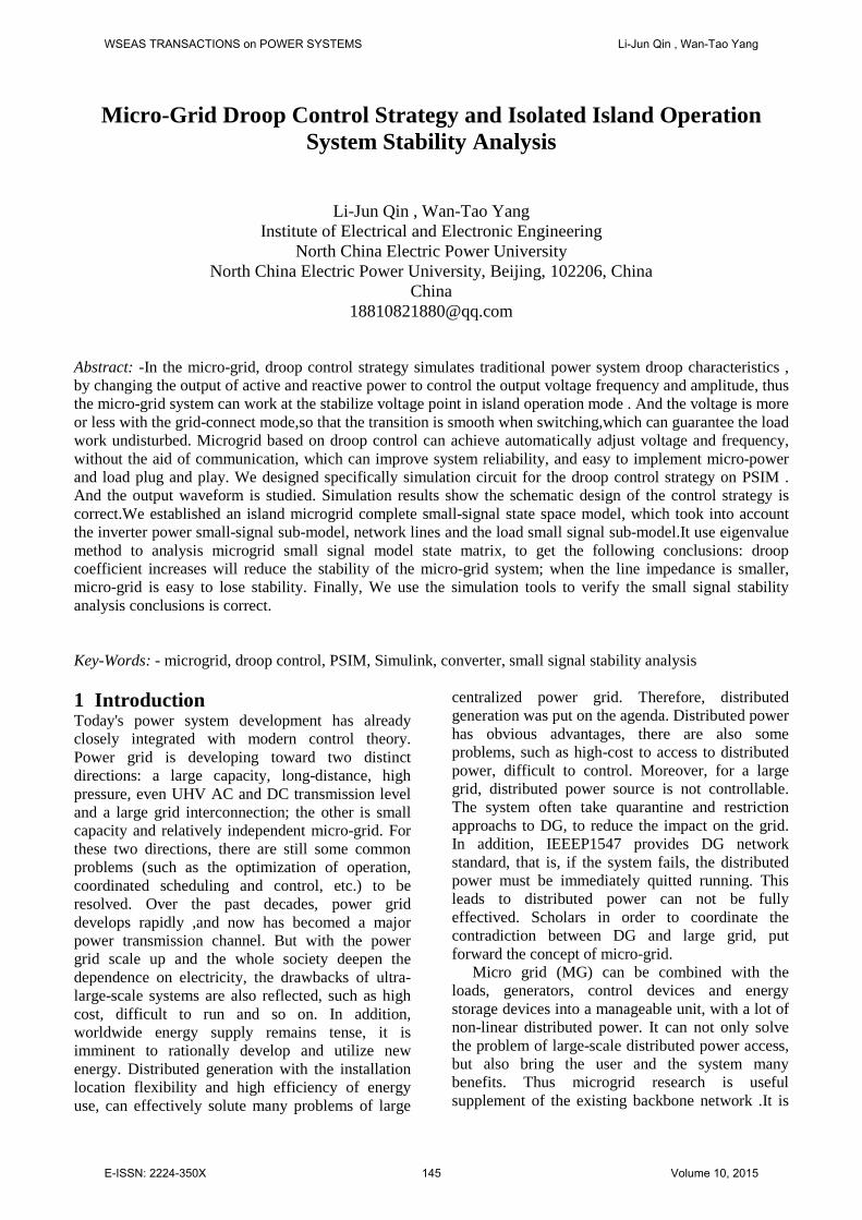
In the micro-grid, the droop control strategy simulates the droop characteristics of traditional power system, by changing the output of active and reactive power to control the frequency and amplitude of the output voltage, so that micro-grid system can work on stabilize voltage point in island operation mode . And it is less different with the network mode voltage.Transition is smooth when switching,that can guarantee the load undisturbed to normally work. The figure below shows the frequency - the active and voltage - reactive droop curve.
Figure 1. drooping curve:(a) f P− droop (b) V-Q droop
Wherein the 0f is no-load frequency. The Nf is the nominal frequency. The minf is minimum frequency for the power quality permission.The NP is nominal active power output. The maxP is maximum power output. The maxV , minV is the maximum and minimum voltage of the system. The
NV is rated voltage. The Qmin, Qmax is the minimum and maximum output reactive power.
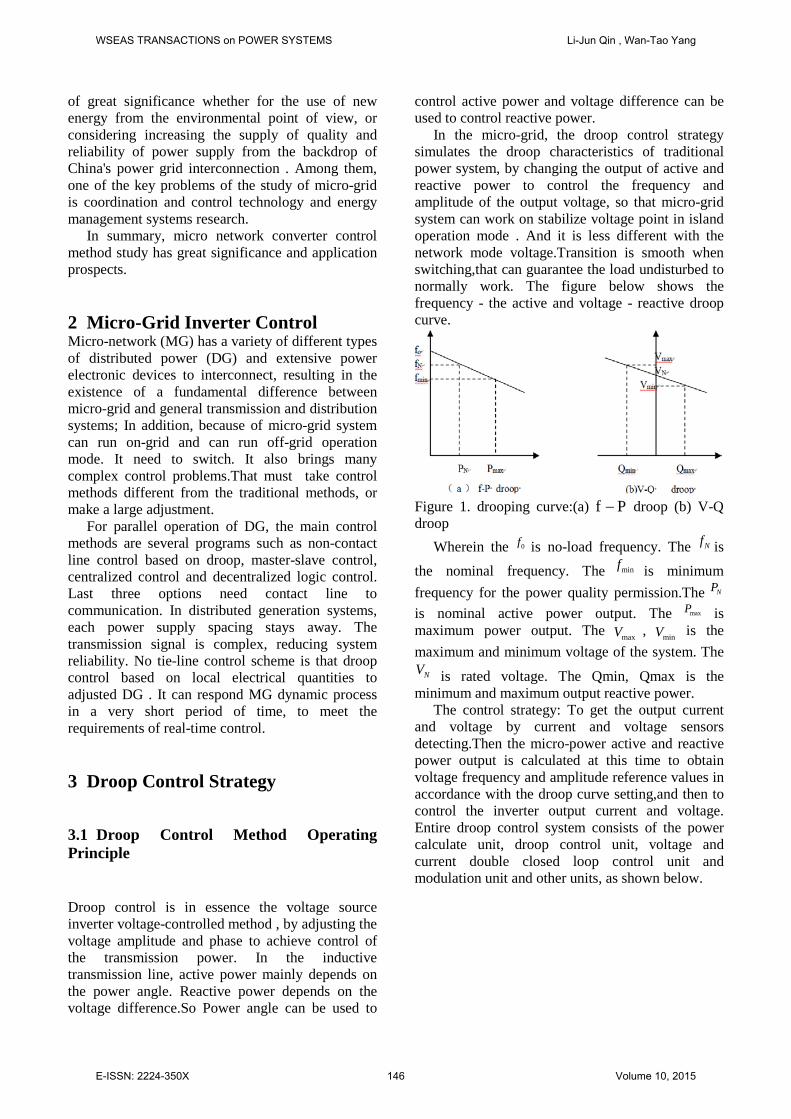
The control strategy: To get the output current and voltage by current and voltage sensors detecting.Then the micro-power active and reactive power output is calculated at this time to obtain voltage frequency and amplitude reference values in accordance with the droop curve setting,and then to control the inverter output current and voltage. Entire droop control system consists of the power calculate unit, droop control unit, voltage and current double closed loop control unit and modulation unit and other units, as shown below.
WSEAS TRANSACTIONS on POWER SYSTEMS Li-Jun Qin , Wan-Tao Yang
E-ISSN: 2224-350X 146 Volume 10, 2015
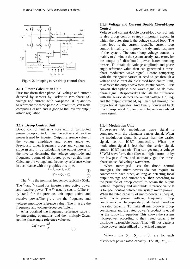
Figure 2. drooping curve droop control chart
3.1.1 Power Calculation Unit First transform three-phase AC voltage and current detected by sensors by Parker to two-phase DC voltage and current, with two-phase DC quantities to represent the three-phase AC quantities, can make computing easier, and is good to the inverter output astatic regulation. 3.1.2 Droop Control Unit Droop control unit is a core unit of distributed power droop control. Enter the active and reactive power issued by inverter. Output reference value of the voltage amplitude and phase angle ωt. Previously given frequency droop and voltage sag slope m and n, by calculating the output power of the inverter determine the voltage amplitude and frequency output of distributed power at this time. Calculate the voltage and frequency reference value in accordance with the graphics this time.
)( PPmff NN −+= (1) )( QQnV N −= (2)
The Nf is the nominal frequency, typically 50Hz. The NP and NQ stand for inverter rated active power and reactive power. The NQ usually sets to 0.The P , Q stand for the previous unit input active and reactive power.The f , V are the frequency and voltage amplitude reference value . The m, n are the frequency and voltage droop coefficient.
After obtained the frequency reference value f, by integrating operations, and then multiply 2πcan get the phase angle reference value ωt.
dtdf δωπ ==2
(3)
3.1.3 Voltage and Current Double Closed-Loop Control Voltage and current double closed-loop control unit is also droop control strategy important aspect, in which the outer ring is the voltage closed-loop. The inner loop is the current loop.The current loop control is mainly to improve the dynamic response of the system. The outer loop voltage control is mainly to eliminate the system steady-state error, for the output of distributed power better tracking presets. To obtain the voltage amplitude and phase angle reference value then can generated a three-phase modulated wave signal. Before comparing with the triangular carrier, it need to get through a voltage and current double closed-loop control unit, to achieve the output waveform astatic control. First convert three-phase sine wave signal to dq two-phase signal. Respectively Calculate the difference with the sensor detects the output voltage Ud, Uq, and the output current id, iq. Then get through the proportional regulator. And finally converted back to a three-phase AC quantities to become modulated wave signal. 3.1.4 Modulation Unit Three-phase AC modulation wave signal is compared with the triangular carrier signal. When the modulation signal is greater than the carrier signal, control IGBT conduction. When the modulation signal is less than the carrier signal, control IGBT turn-off. That can get output voltage SPWM waveform, then filter out high harmonics by the low-pass filter, and ultimately get the three-phase sinusoidal voltage waveform.
When micro-grid uses the droop control strategies, the micro-powers do not require to contact with each other, as long as detecting local output voltage and current size, then according to the principle of droop control to obtain the output voltage frequency and amplitude reference value.It is for peer control between the system micro power . When the rated capacity of micro-power is unequal, each micro power voltage, frequency droop coefficients can be separately calculated based on the rated capacity .To make all micro-power droop coefficients and the rated power’s product is equal ,as the following equation. This allows the system micro-power according to their rated capacity to distribute reasonable loads .That will not cause a micro power underutilized or overload damage.
Wherein the 1S , 2S ...... Sn are for each
distributed power rated capacity. The 1m , 2m , ......
WSEAS TRANSACTIONS on POWER SYSTEMS Li-Jun Qin , Wan-Tao Yang
E-ISSN: 2224-350X 147 Volume 10, 2015
are each distributed active power droop curves slope. The 1n , 2n ...... are each distributed active power droop curves slope. 3.2 Build Simulation Models 3.2.1 Droop Control Unit Set the rated voltage amplitude 311V and rated frequency 50Hz. Set rated active power and reactive power 4000 and 2000 respectively. Active and reactive droop coefficient are 0.0005 and 0.01 respectively.Generated phase δ is as other aspects ωt input.
Figure 3. droop control unit
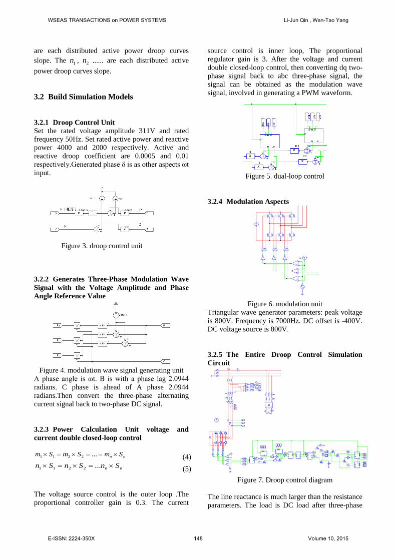
3.2.2 Generates Three-Phase Modulation Wave Signal with the Voltage Amplitude and Phase Angle Reference Value
Figure 4. modulation wave signal generating unit
A phase angle is ωt. B is with a phase lag 2.0944 radians. C phase is ahead of A phase 2.0944 radians.Then convert the three-phase alternating current signal back to two-phase DC signal. 3.2.3 Power Calculation Unit voltage and current double closed-loop control
nn SmSmSm ×==×=× ...2211 (4) nn SnSnSn ×=×=× ...2211 (5)
The voltage source control is the outer loop .The proportional controller gain is 0.3. The current
source control is inner loop, The proportional regulator gain is 3. After the voltage and current double closed-loop control, then converting dq two-phase signal back to abc three-phase signal, the signal can be obtained as the modulation wave signal, involved in generating a PWM waveform.
Figure 5. dual-loop control
3.2.4 Modulation Aspects
Figure 6. modulation unit
Triangular wave generator parameters: peak voltage is 800V. Frequency is 7000Hz. DC offset is -400V. DC voltage source is 800V. 3.2.5 The Entire Droop Control Simulation Circuit
Figure 7. Droop control diagram
The line reactance is much larger than the resistance parameters. The load is DC load after three-phase
WSEAS TRANSACTIONS on POWER SYSTEMS Li-Jun Qin , Wan-Tao Yang
E-ISSN: 2224-350X 148 Volume 10, 2015

bridge rectifier circuit . Voltage sensor measured current through the low-pass filter cut-off frequency is 1000Hz. Power calculation unit output active and reactive power also need to go through the filtering effect. The cutoff frequency is setted to 1000Hz. Modulation wave signal need enter a restrictor bofore through a comparator, limiting the amplitude of the waveform. The parameter is setted from -400V to + 400V. 3.3 Simulation results Triangular wave generator parameters: peak voltage is 800V. Frequency is 7000Hz. DC offset is -400V. DC voltage source is 800V.
1) Inverter output three-phase current and voltage are shown in figure below, showing the output current stabilized after 0.04 seconds, and control is the rapid.
(a) output current
(b) output voltage
Figure 8. (a) output current (b) output voltage Output voltage after low-pass filter is as shown.
Figure 9. low-pass filter output voltage
2) Output voltage amplitude: 222βα UUUm += (6)
It is consistent with figure the output voltage waveform magnitude.
Figure 10. Output voltage amplitude 3) output active power and reactive power:
Figure 11. Output active power
Active power stabilized at about 2kW, and is less different with values calculated by the inverter output voltage and current.
Figure 12. reactive power output
Reactive power is about 7kVar 4) voltage magnitude and phase angle reference
value:
Figure 13. voltage amplitude and phase angle
Level curve is voltage amplitude pattern. Tilt curves is angle graphics. The voltage amplitude reference value is about 270V. The slope of the curve of the phase angle curve is approximately 317.08.That can calculate at this time frequency reference value is 50.46Hz .
4 Islands Microgrid Small Signal Stability Analysis Compared with the large grid, microgrid capacity is generally small. The system inertia with respect to the bulk power system inertia can even be negligible. Therefore when micro power grid operation with grid, dynamic process and stability of the system depends on the power grid; And when islanding operation, the stability of the microgrid depends on its own control part and network structure, susceptible to disturbances and loss of stability. One of the important conditions for safe and stable operation of the microgrid under islanding state is able to maintain its small signal stability. The time
WSEAS TRANSACTIONS on POWER SYSTEMS Li-Jun Qin , Wan-Tao Yang
E-ISSN: 2224-350X 149 Volume 10, 2015
constant of large power rotation generators and control systems is much larger than the time constant of the network, so the network and load can use no dynamic equivalent impedance model. The traditional power systems small signal stability analysis often neglects network dynamics characteristics impact. In the small signal stability analysis of the micro-grid, due to the micro-power mostly through the very short response time power electronic inverter access, dynamic characteristics of the network will affect the stability of the system.
In this paper, the establishment of microgrid islands small-signal model fully consider the impact of network dynamics. It establish inverter control system small-signal sub-model and the network line small-signal sub-model considering the dynamic characteristics and load small-signal sub-models. These sub-models are established at their rotating coordinate system.Through coordinate transformation, all the sub-models are converted into a unified reference coordinate system and combined to establish a complete micro-grid small-signal state space model, to get the system state matrix , to analysis stability caused by the parameters change by characteristic value method.
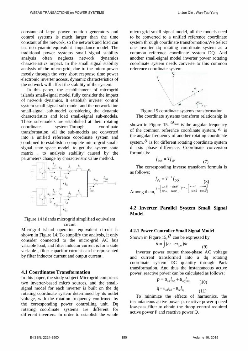
Figure 14 islands microgrid simplified equivalent circuit
Microgrid island operation equivalent circuit is shown in Figure 14. To simplify the analysis, it only consider connected to the micro-grid AC bus variable load, and filter inductor current is for a state variable , filter capacitor current can be represented by filter inductor current and output current . 4.1 Coordinates Transformation In this paper, the study subject Microgrid comprises two inverter-based micro sources, and the small-signal model for each inverter is built on the dq rotating coordinate system determined by its outlet voltage, with the rotation frequency confirmed by the corresponding power controlling unit. Dq rotating coordinate systems are different for different inverters. In order to establish the whole
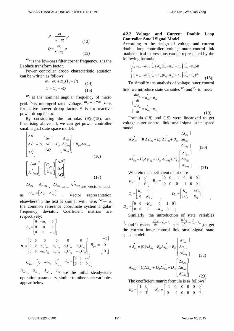
micro-grid small signal model, all the models need to be converted to a unified reference coordinate system through coordinate transformation.We Select one inverter dq rotating coordinate system as a common reference coordinate system DQ. And another small-signal model inverter power rotating coordinate system needs converte to this common reference coordinate system.
Figure 15 coordinate systems transformation
The coordinate systems transform relationship is
shown in Figure 15. comω is the angular frequency of the common reference coordinate system. ω is the angular frequency of another rotating coordinate system.θ is for different rotating coordinate system d axis phase difference. Coordinate conversion formula is:
DQ dqf Tf= (7) The corresponding inverse transform formula is
as follows: 1
dq DQf T f−= (8)
Among them,cos sinsin cos
Tθ θθ θ
− = ,
1 cos sinsin cos
Tθ θθ θ
− = −
4.2 Inverter Parallel System Small Signal Model 4.2.1 Power Controller Small Signal Model Shown in Figure 15,θ can be expressed by
( )com dtθ ω ω= −∫ (9) Inverter power output three-phase AC voltage
and current transformed into a dq rotating coordinate system DC quantity through Park transformation. And thus the instantaneous active power, reactive power can be calculated as follows:
od od oq oqp u i u i= + (10) od od oq oqq u i u i= − (11)
To minimize the effects of harmonics, the instantaneous active power p, reactive power q need low-pass filter to obtain the droop control required active power P and reactive power Q.
WSEAS TRANSACTIONS on POWER SYSTEMS Li-Jun Qin , Wan-Tao Yang
E-ISSN: 2224-350X 150 Volume 10, 2015
c
c
P psωω
=+ (12)
c
c
Q qsωω
=+ (13)
cω is the low-pass filter corner frequency. s is the Laplace transform factor.
Power controller droop characteristic equation can be written as follows:
( )n p nm P Pω ω= + − (14) oU U nQ= − (15)
nω is the nominal angular frequency of micro grid. oU is microgrid rated voltage. 2pm mπ= . m is for active power droop factor. n is for reactive power droop factor.
By considering the formulas (9)to(15), and linearising above all, we can get power controller small signal state-space model:
ldq
p p odq p com
odq
iP A P B u B
Q iQ
ω
θ θω
•
•
•
∆ ∆ ∆ ∆ = ∆ + ∆ + ∆ ∆ ∆ ∆ (16)
p
puodq
CP
CQu
ω
θω∗
∆ ∆ = ∆ ∆ ∆ (17)
ldqi∆、 odqu∆
、 odqi∆ and odqu∗
∆ are vectors, such
asT
ldq ld lqi i i ∆ = ∆ ∆ . Vector representation elsewhere in the text is similar with here. comω∆ is the common reference coordinate system angular frequency deviator. Coefficient matrixs are respectively:
0 00 00 0
p
p c
c
mA ω
ω
− = − −
0 0 0 0 0 00 00 0
p c od c oq c od c oq
c oq c od c oq c od
B I I U UI I U U
ω ω ω ωω ω ω ω
= − − ,
100
pB ω
− =
0 0p pC mω = − ,
0 00 0 0pu
nC
− = ,
odU 、 oqU 、 odI 、 oqI are the initial steady-state operation parameters, similar to other such variables appear below.
4.2.2 Voltage and Current Double Loop Controller Small Signal Model According to the design of voltage and current double loop controller, voltage outer control link mathematical expressions can be represented by the following formula:
( ) ( )
( ) ( )
ld od f oq up od od ui od od
lq oq f od up oq oq ui oq oq
i i C u K u u K u u dt
i i C u K u u K u u dt
ω
ω
∗ ∗ ∗ ∗
∗ ∗ ∗ ∗
= − + − + − = − + − + −
∫
∫ (18) To simplify the analysis of voltage outer control
link, we introduce state variables dψ and qψ to meet: d
od od
qoq oq
d u udt
du u
dt
ψ
ψ
∗
∗
= − = − (19)
Formula (18) and (19) were linearized to get voltage outer control link small-signal state space model:
*
1 2[0]ldq
dq dq u odq u odq
odq
iB u B u
iψ ψ
• ∆ ∆ = ∆ + ∆ + ∆ ∆ (20)
* *
1 2
ldq
ldq u dq u odq u odq
odq
ii C D u D u
iψ
∆ ∆ = ∆ + ∆ + ∆ ∆ (21)
Wherein the coefficient matrix are
1
1 00 1uB
= ,
2
0 0 1 0 0 00 0 0 1 0 0uB
− = −
00
uiu
ui
KC
K
= ,
1up f
uf up
K CD
C Kω
ω−
= ,
2
0 0 0 1 00 0 0 0 1
upu
up
KD
K−
= − Similarly, the introduction of state variables
dλ and qλ meets d
ld ldd i idtλ ∗
= − can
qlq lq
di i
dtλ ∗
= −,to get
the current inner control link small-signal state space model:
1 2[0]ldq
dq dq i ldq i odq
odq
iB i B u
iλ λ• ∗
∆ ∆ = ∆ + ∆ + ∆ ∆ (22)
1 2
ldq
idq i dq i ldq i odq
odq
iu C D i D u
iλ
∗ ∆ ∆ = ∆ + ∆ + ∆ ∆ (23)
The coefficient matrix formula is as follows:
1
1 00 1iB
= ,
2
1 0 0 0 0 00 1 0 0 0 0iB−
= −
WSEAS TRANSACTIONS on POWER SYSTEMS Li-Jun Qin , Wan-Tao Yang
E-ISSN: 2224-350X 151 Volume 10, 2015
0 00 0iC
= ,
1
00i
KD
K
= ,
2
0 0 0 00 0 0 0
fi
f
K LD
L Kω
ω− −
= − 4.2.3 Output Filters and Network Small-Signal Model Inverter powers via the output LC filter access to
micro-grid AC bus line. Filter inductor current li ,
inverter power output voltage ou and output current oi meet the following differential algebra equation:
ldf id od f ld f lq
lqf iq oq f lq f ld
odf ld od f oq
oqf lq oq f od
odod Cd od oq
oqoq Cq oq od
diL u u R i L idtdi
L u u R i L idt
duC i i C udt
duC i i C u
dtdiL u u Ri Lidt
diL u u Ri Li
dt
ω
ω
ω
ω
ω
ω
= − − + = − − + = − + = − + = − − + = − − + (24)
fR is for damping resistor for the filter oscillation suppression, R , L is the line resistance and inductance. Cdu 、 Cqu are microgrid AC bus voltage d, q-axis component.
We use microgrid initial steady state operating point angular frequency oω to linearise the formula (24) to get the output filter and the network small signal state-space model:
ldqldq
odq LW odq LW idq LW Cdq LW
odqodq
i iu A u B u C u D
ii
ω
•
•
•
∆ ∆ ∆ = ∆ + ∆ + ∆ + ∆ ∆ ∆ (25) Wherein the coefficient matrix are
1 0 0 0
10 0 0
1 10 0 0
1 10 0 0
10 0 0
10 0 0
fo
f f
fo
f f
of fLW
of f
o
o
RL L
RL L
C CA
C CR
L LR
L L
ω
ω
ω
ω
ω
ω
− − − − − − = − − − − − ,
1 0
10
0 00 00 00 0
f
fLW
L
LB
= ,
0 00 00 00 01 0
10
LWC
L
L
= − −
T
LW lq ld oq od oq odD I I U U I I = − − −
4.2.4 Inverter Power Parallel System Small Signal Model All the above portions small signal model are established under the rotating coordinate system determined by inverter power output voltage. In order to establish the entire micro-grid system small-signal model, these models need to be converted to the common reference coordinate system.
According to coordinate transformation method described above, inverter power output current converted to the common reference coordinate system is:
cos sinsin cosoDQ odq odqi Ti i
θ θθ θ
− = =
(26) Linearize formula (26) can get
oDQ odq ii Ti T θ= = ∆ (27)
Wherein the iT is matrix contains two elements. Its expression is
sin coscos sin
od oqi
od oq
I IT
I Iθ θθ θ
− − = −
Microgrid AC bus voltage is a variable in the common reference coordinate system. It can convert to the inverter itself rotating coordinate system using coordinate inverse transformation formula.
1 cos sinsin cosCdq CDQ CDQu T u uθ θθ θ
− = = − (28)
Linearize formula (28) can get 1 1
Cdq CDQ uu T u T θ− −∆ = + ∆ (29)
Wherein 1 sin cos
cos sinCD CQ
uCD CQ
U UT
U Uθ θθ θ
−− +
= − − By considering the formulas(8)-(29), we can
obtain inverter power x small signal state-space model:
cominvx invx invx invx CDQ x com
x inv xinvx
oDQx invcx
x A x B u B
Cx
i C
ω
ω
ω
ω
•∆ = ∆ + ∆ + ∆ ∆ = ∆ ∆ (30)
T
invx x x x dqx dqx ldqx odqx odqxx P Q i u iθ ψ λ ∆ = ∆ ∆ ∆ ∆ ∆ ∆ ∆ ∆ , the coefficient matrix are
(3 3) 3 2 3 2 (3 6)
1 2 3 2 2 2 2 2(2 6)
1 1 2 3 1 2 2 2 2 1 2 2 2 6
1 1
1 212 1 2 1 1 6 2 6 2
2
6 3
0 0( ) 0 0
( ) ( ) 0 ( )
0 0 ( ) ( )
p p
u pu u
i u pu i u i u i
invx LW i u pu
LW LW i uLW u LW i u LW i
LW i
LW p
A BB C B
B D C B C B D BA B D D C
A B D DC T B D C B C
B DD C ω
× × × ×
× × × ×
× × × ×
−× × × ×
×
+= +
+ + + 6 6
13 13
×
×
WSEAS TRANSACTIONS on POWER SYSTEMS Li-Jun Qin , Wan-Tao Yang
E-ISSN: 2224-350X 152 Volume 10, 2015
3 2
2 2
2 21
6 2 13 2
000
( )
invx
LW
B
C T
×
×
×−
× ×
= ,
3 1
2 1
2 1
6 1 13 1
( )000
com
p
x
B
B
ω
ω
×
×
×
× ×
=
( ) 1 2 1 2 1 61 3 1 130 0 0inv x pC Xω ω × × ×× ×
= [ ] [ ]2 1 2 1 2 1 2 2 2 2 2 2 2 2 2 22 3 2 6 2 13
0 0 0 0 0 0invcx iC T T× × × × × × × ×× × × =
In this paper, micro-grid system contains two inverter power . Usually the first inverter rotating coordinate system is as a common reference coordinate system, thus
[ ]0 0 1
0 0 0 1p
p
m xX
xω
− = = ≠
In sum, two inverters parallel system small signal state space model is:
1 1
22
1
2
inv invinv inv CDQ
invinv
invoDQ inv
inv
x xA B u
xx
xi C
x
•
•
∆ ∆ = + ∆ ∆ ∆ ∆ ∆ = ∆ (31)
The coefficient matrix formulas are as follows: 1 1 1 13 13 13 13
2 1 13 13 2 26 26
( ) 0
( )com
com
inv invinv
inv inv
A B CA
B C Aω ω
ω ω
× ×
× ×
+ =
1
2 26 2
invinv
inv
BB
B×
= ,
1 2 13
2 13 2 4 26
00
invcinv
invc
CC
C×
× ×
=
4.3 Load small-signal model load current loadi meets the following differential algebra equation:
loadDload CD load loadD load loadQ
loadQload CQ load loadQ load loadD
diL u R i L idt
diL u R i L i
dt
ω
ω
= − + = − − (32) Formula (32) were linearized small signal load
available state-space model: 1 2loadDQ Load loadDQ Load CDQ Loadi A i B u B ω∆ = ∆ + ∆ + ∆ (33)
Wherein the coefficient matrices are
loado
loadLoad
loado
load
RL
ARL
ω
ω
− =
− ,
1
1 0
10
loadLoad
load
LB
L
= ,
2loadQ
LoadloadD
IB
I
= −
4.4 micro-grid small-signal model From(31)and (33) , it can be seen that micro-grid AC bus voltage is input variables for each sub-
model, and through micro-grid AC bus voltage , each subsystem can be combined to form a complete micro-grid small-signal state space model.
In order to better determine the micro-grid AC
bus voltage , We assume that nr is the exchange for micro-grid AC bus virtual resistance to ground. In order to reduce the impact on system dynamic stability, nr general should choose a larger value, here 73 10× Ω .
Therefore, micro-grid AC bus voltage can be expressed as
1 2( )CD n oD oD loadDu r i i i= + − (34) 1 2( )CQ n oD oD loadQu r i i i= + − (35)
Formula (34) and (35) can be linearized to get CDQ N inv oDQ N load loadDQu R M i R M i∆ = ∆ + ∆ (36)
The coefficient matrix formulas are as follows: 0
0n
Nn
rR
r
= ,
1 0 1 00 1 0 1invM
= ,
1 00 1loadM−
= − By considering the formulas(31)(33)(36),and
eliminating intermediate variables, we can get microgrid system complete small-signal state space model:
inv invmg
loadDQloadDQ
x xA
ii
•
•
∆ ∆ = ∆ ∆ (37)
Wherein [ ]1 2T
inv inv invx x x∆ = ∆ ∆ ,the coefficient matrices are
26 26 26 2
1 2 2 26 1 2 2 28 28
( ) ( )( ) ( )
inv inv N inv inv inv N loadmg
Load N inv inv Load inv inv Load N load
A B R M C B R MA
B R M C B C A B R Mω
× ×
× × ×
+ = + +
[ ]1 2 1 26inv inv invC C Cω ω ω ×
=
4.5 different parameters affect the stability analysis As we already established a microgrid islands small-signal state space model , eigenvalue analysis of its state matrix is an important means to determine the micro-grid stability, but also of change of different parameters such as active and reactive droop factor, line parameters effect on the stability. Table 1 Islands microgrid stable operating parameters Parameters(Value)
Parameters(Value)
Parameters(Value)
Parameters(Value)
odU [311.2 311.2]
oqU [0 0] odI [3.3 3.3]
oqI [0.4 1.2]
WSEAS TRANSACTIONS on POWER SYSTEMS Li-Jun Qin , Wan-Tao Yang
E-ISSN: 2224-350X 153 Volume 10, 2015
ldI [3.5 3.5]
lqI [1.5 2.3]
CDU [310.8] CQU [0]
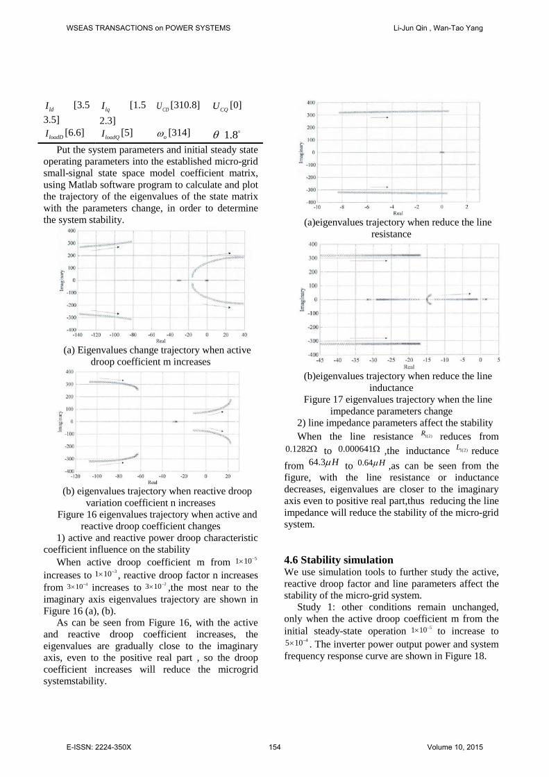
loadDI [6.6] loadQI [5] oω [314] θ 1.8 Put the system parameters and initial steady state
operating parameters into the established micro-grid small-signal state space model coefficient matrix, using Matlab software program to calculate and plot the trajectory of the eigenvalues of the state matrix with the parameters change, in order to determine the system stability.
(a) Eigenvalues change trajectory when active
droop coefficient m increases
(b) eigenvalues trajectory when reactive droop
variation coefficient n increases Figure 16 eigenvalues trajectory when active and
reactive droop coefficient changes 1) active and reactive power droop characteristic
coefficient influence on the stability When active droop coefficient m from 51 10−×
increases to 31 10−× , reactive droop factor n increases from 43 10−× increases to 23 10−× ,the most near to the imaginary axis eigenvalues trajectory are shown in Figure 16 (a), (b).
As can be seen from Figure 16, with the active and reactive droop coefficient increases, the eigenvalues are gradually close to the imaginary axis, even to the positive real part , so the droop coefficient increases will reduce the microgrid systemstability.
(a)eigenvalues trajectory when reduce the line
resistance
(b)eigenvalues trajectory when reduce the line
inductance Figure 17 eigenvalues trajectory when the line
impedance parameters change 2) line impedance parameters affect the stability When the line resistance 1(2)R reduces from
0.1282Ω to 0.000641Ω ,the inductance 1(2)L reduce from 64.3 Hµ to 0.64 Hµ ,as can be seen from the figure, with the line resistance or inductance decreases, eigenvalues are closer to the imaginary axis even to positive real part,thus reducing the line impedance will reduce the stability of the micro-grid system.
4.6 Stability simulation We use simulation tools to further study the active, reactive droop factor and line parameters affect the stability of the micro-grid system.
Study 1: other conditions remain unchanged, only when the active droop coefficient m from the initial steady-state operation 51 10−× to increase to
45 10−× . The inverter power output power and system frequency response curve are shown in Figure 18.
WSEAS TRANSACTIONS on POWER SYSTEMS Li-Jun Qin , Wan-Tao Yang
E-ISSN: 2224-350X 154 Volume 10, 2015

Figure 18 simulation waveforms of active droop
coefficients 45 10m −= × As can be seen from Figure 18, when the active
droop coefficient m is larger, inverter power output active and reactive power and system frequency will produce oscillation, micro-grid system becoming unstable.
Example 2: other conditions remain unchanged, only when the reactive droop coefficient n increases from the initial steady-state operation 43 10−× to
33 10−× ,inverter power 1 output power and micro-grid AC bus voltage response curve are shown in Figure 19. As we can be seen from the figure, when n is larger, the inverter output active and reactive power fluctuation is larger, and deviates from the initial steady-state operation value. Microgrid AC bus voltage amplitude drop magnitude is beyond the initial steady-state operating voltage amplitude fluctuations allowed taxis 5% range. Therefore, when the reactive droop factor n increases, the micro-grid system is easy to lose stability.
Operation example 3: other conditions remain unchanged, when the line impedance parameters from the initial steady-state operation 1(2) 0.1282R = Ω , 1(2) 64.3L Hµ= reduced to
1(2) 0.016025R = Ω , 1(2) 8.0375L Hµ= ,the inverter power 1 output power and system frequency response curve are shown in Figure 20. As we can be seen from the figure, when the line impedance parameters is smaller, inverter power output active power, reactive power and system frequency will produce oscillation.And micro-grid system will lose stability.
Figure 19 The reactive droop coefficient
33 10n −= × simulation waveforms
Figure 20 line impedance
parameters 1(2) 0.016025R = Ω , 1(2) 8.0375L Hµ= simulation waveform
Simulation results show that the micro-grids small signal stability analysis related conclusions are correct . We can use these results to take appropriate measures to enhance the stability of the micro-grid system. For example when the line impedance is small, we can string into proper little resistance and inductance, droop coefficient, etc.
5 Conclusion and Outlook 5.1 Conclusion and Summary Microgrid based on droop control can achieve automatically adjust voltage and frequency, without the aid of communication, which can improve system reliability, and easy to implement micro-power and load plug and play. This article describes the micro-grid inverter study background and significance.The working principle of micro-grid droop control method is studied and built their model circuit diagram on psim software. After simulation operation, the output waveforms show that the control strategy designed can stabilize the output power, and satisfy the system requirements of voltage amplitude and frequency.That proves the correctness of such a microgrid control strategy. It has established an island microgrid complete small-signal state space model, which took into account
WSEAS TRANSACTIONS on POWER SYSTEMS Li-Jun Qin , Wan-Tao Yang
E-ISSN: 2224-350X 155 Volume 10, 2015
the inverter power small-signal sub-model, network lines and the load small signal sub-model.Use eigenvalue method to analysis microgrid small signal model state matrix, to get the following conclusions: droop coefficient increases will reduce the stability of the micro-grid system; when the line impedance is smaller, micro-grid is easy to lose stability. Finally, We use the simulation tools to verify the small signal stability analysis conclusions is correct. 5.2 Prospects Due to time constraints, as well as lack of practical experience, this article only do a little preliminary researchs on micro-grid inverter control this broad field, which will inevitably be some flaws. We also need to do more research in the following areas and learning:
1) DC side uses a DC voltage source, in less ideal circumstances, the distributed power situation is very complex.There are intermittent and persistent type of distributed power generation division.
2) This article is aimed at small perturbation to analyze the stability of the micro-grid.It need further study on micro-grid system transient stability dealing with large disturbances. References: [1] R.Lasseter; A.Abbas; C.Marnay,and Etal.
Integration of distributed energy resources. The CERTS MicroGrid concept 2003.
[2] A.Arulampalam;M.Barnes;A.Engler,and Etal. Control of power electronic interfaces in distributed generation MicroGrids. International Journal of Electronics 2004, 91, 503-523.
[3] S.Morozumi. Micro-grid demonstration projects in Japan. In Proceedings of the Fourth Power Conversion Conference-NAGOYA, Japan,2007; pp. 635-642.
[4] De Brabandere K. Voltage and frequency droop control in low voltage grids by distributed generators with inverter front-end. Faculties Ingenieursw-etenschappen K.U.Leuven, Belium, 2006.
[5] Venkataramanan Marnay C. A Larger Role for Microgrids. IEEE Power Energy Magazine 2008, 6, 78-82.
[6] Katiraei F Iravani M R, Lehn P W. Micro-grid Autonomous Operation During an d Subsequent to Islanding Process. IEEE Trans on Power Delivery 2004.
[7] Yang,R.-H.;Huang,W.;Guan,L.;Liu,L.-F. Micro-grid structure and operational control. Grid and Clean Energy 2010, 26, 48-55.
[8] Luo,R.-X.;Liu,C.-Z.;You,X.-L.;Liu,T.-J. Micro-grid island mode a variety of droop control strategies research. Sichuan Electric Power Technology 2012, 35, 11-20.
[9] Yang,H.-M.;Song,J.-C. Single-phase voltage-type PWM inverter modeling and simulation Based on double loop control. Electrical Technology 2008, 5, 72-75.
[10] Song,Z.-R.;Zhao,Y.-L.;Hu,X.-T.;Song,Y. PWM inverter modeling and dual-loop control strategy. Grid and Clean Energy 2009, 25, 53-57.
[11] Gong,C.-S.;Gong,S.-X. Some Problems of distributed generation energy supply system. Automation of Electric Power Systems 2008, 32, 1-4.
[12] Lu,Z.-X.;Wang,C.-X.;Min,Y. Review of microgrid. Power System and Automation 2007, 31, 100-104.
[13] Guo,H.;Su,J.-H.;Zhang,G.-R. Microgrid technology research Status. Sichuan Electric Power Technology 2009, 32, 1-6.
[14] Liang,Y.-W.;Hu,Z.-J.;Chen,Y.-P. Review of Distributed Generation and Application in Power System. Grid technology 2003, 27, 71-75.
[15] Wang,Z.-Q.;Zhu,S.-Z.;Zhou,S.-X. Impact of Distributed Generation on Distribution System Voltage Distribution. Automation of Electric Power Systems 2004, 28, 56-60.
[16] Zheng,Z.-H.Ai,Q. Microgrid Research Status and Application Prospects in China. Grid technology 2008.
[17] Li,S.;Wang Z.-X.;Wang G.-Q. A Feedback Linearization Based Control Strategy for VSC-HVDC Transmission Converters. WSEAS TRANSACTIONS on SYSTEMS 2011,2,49-58.
[18] Zhao,Y.;Yu,E.-J. The new distributed generation device-microturbines. Grid technology 2004, 28, 47-50.
[19] Tain-Sou TSAY. Stability Analyses of Nonlinear Multivariable Feedback Control Systems. WSEAS TRANSACTIONS on SYSTEMS 2012, 4, 140-151.
[20] Geng,X.; Yang,J.-X.; Zhang,Z.-M.; Tang,H.-J.; Bai,L.-Y. DC Characteristic Analysis of Three-Phase LC Filter- Uncontrollable Rectifier Using Circuit DQ Transformation. WSEAS TRANSACTIONS on SYSTEMS and CONTROL 2011,8,314-324.
WSEAS TRANSACTIONS on POWER SYSTEMS Li-Jun Qin , Wan-Tao Yang
E-ISSN: 2224-350X 156 Volume 10, 2015