governor and droop basics_final
TRANSCRIPT
8/10/2019 Governor and Droop Basics_Final
http://slidepdf.com/reader/full/governor-and-droop-basicsfinal 1/5
11/10/20
Awareness Program for Operation Staff
Understanding of
Generator Governor and Droop
Kotmale Power Station
January , 2010
By:
Eng., Nizam Salih
Electrical Engineer (Operations)
Session 2
Contents
1. What is a Governor
2. Purposes of a Speed Governor
3. Isochronous Operation
4. What is Droop
5. Percentage Speed Droop
6. Parallel Operation on a Large (Infinite) Bus
7. During Start and Normal Operation
1. What is a Governor
A governor senses the speed (or load) of a prime mover and controls the fuel to
the prime mover to maintain its speed (or load) at a desired level.
Prime mover - engine, turbine, or other source of power
Example:
If you’ve ever driven a car, you’ve functioned as a governor when you control
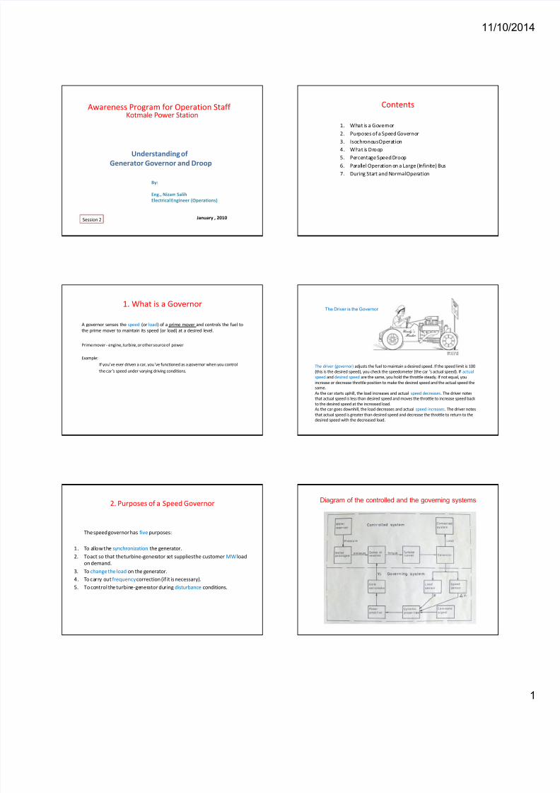
the car’s speed under varying driving conditions.The driver (governor) adjusts the fuel to maintain a desired speed. If the speed limit is 100
(this is the desired speed), you check the speedometer (the car’s actual speed). If actual
speed and desired speed are the same, you hold the throttle steady. If not equal, you
increase or decrease throttle position to make the desired speed and the actual speed thesame.
As the car starts uphill, the load increases and actual speed decreases. The driver notes
that actual speed is less than desired speed and moves the throttle to increase speed back
to the desired speed at the increased load.As the car goes downhill, the load decreases and actual speed increases. The driver notes
that actual speed is greater than desired speed and decrease the throttle to return to thedesired speed with the decreased load.
The Driver is the Governor
2. Purposes of a Speed Governor
The speed governor has five purposes:
1. To allow the synchronization the generator.
2. To act so that the turbine-generator set supplies the customerMW loadon demand.
3. To change the load on the generator.
4. To carry outfrequencycorrection (if it is necessary).
5. To control the turbine-generator duringdisturbance conditions.
Diagram of the controlled and the governing systems
8/10/2019 Governor and Droop Basics_Final
http://slidepdf.com/reader/full/governor-and-droop-basicsfinal 2/5
11/10/20
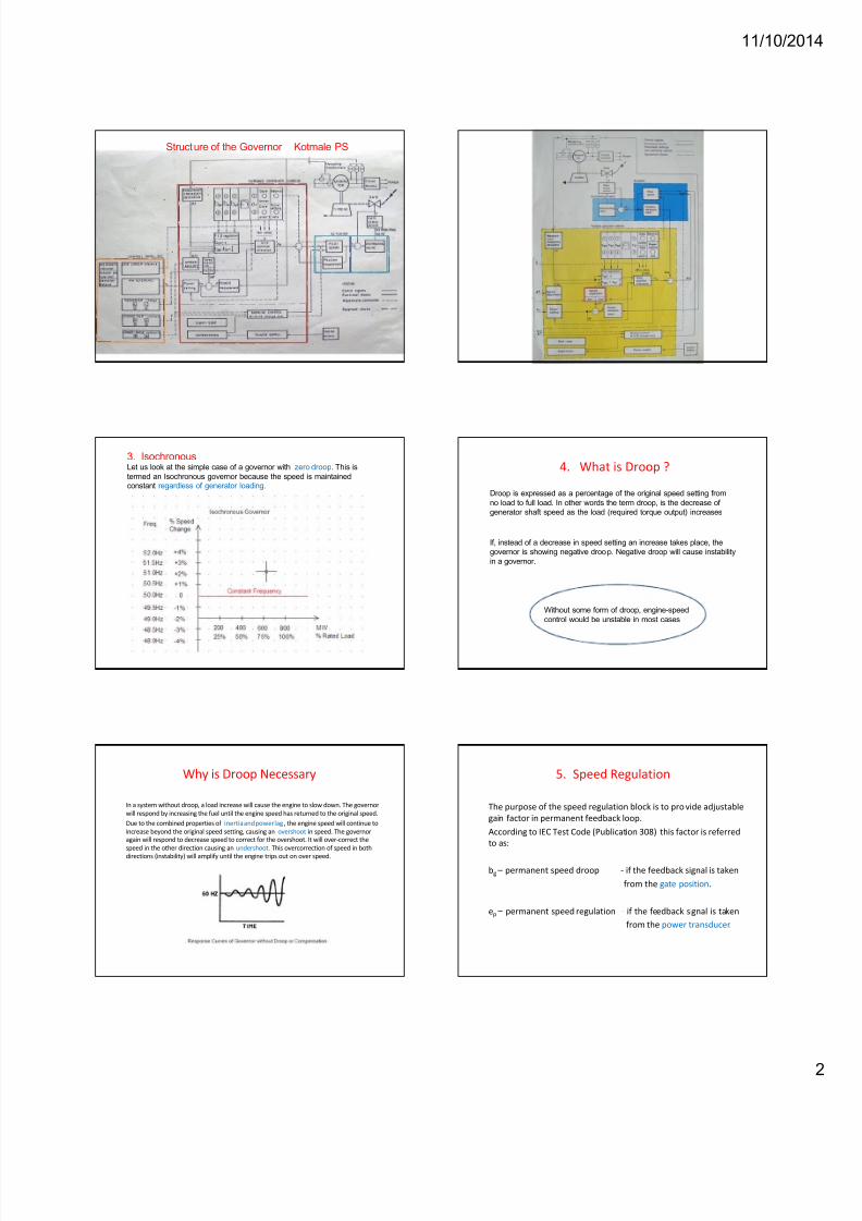
Structure of the Governor Kotmale PS
3. IsochronousLet us look at the simple case of a governor with zero droop. This is
termed an Isochronous governor because the speed is maintainedconstant regardless of generator loading.
4. What is Droop ?
Droop is expressed as a percentage of the original speed setting from
no load to full load. In other words the term droop, is the decrease of
generator shaft speed as the load (required torque output) increases
If, instead of a decrease in speed setting an increase takes place, the
governor is showing negative droop. Negative droop will cause instability
in a governor.
Without some form of droop, engine-speed
control would be unstable in most cases
Why is Droop Necessary
In a system without droop, a load increase will cause the engine to slow down. The governor
will respond by increasing the fuel until the engine speed has returned to the original speed.
Due to the combined properties of inertia and power lag, the engine speed will continue to
increase beyond the original speed setting, causing an overshoot in speed. The governor
again will respond to decrease speed to correct for the overshoot. It will over-correct the
speed in the other direction causing an undershoot. This overcorrection of speed in both
directions (instability) will amplify until the engine trips out on over speed.
5. Speed Regulation
The purpose of the speed regulation block is to provide adjustable
gain factor in permanent feedback loop.
According to IEC Test Code (Publication 308) this factor is referred
to as:
bg – permanent speed droop - if the feedback signal is taken
from the gate position.
ep – permanent speed regulation - if the feedback signal is taken
from the power transducer.

8/10/2019 Governor and Droop Basics_Final
http://slidepdf.com/reader/full/governor-and-droop-basicsfinal 3/5
11/10/20
Speed Droop
In operation, the governor opens/closes the water valves in proportion
of the speed dec rease/increase detected as compared to the total speed
change allowed from no-load to full-load. The governor feedback
control will continue to adjust the valves until the speed error is zero.
The allowable speed change is determined from the droop setting.
Proportional Band
Tmech
Telec.
n0 = shaft rated
speed (rpm)
When Telec. = Tmech , n0 = constant.
When Telec. > Tmech , n < n0
When Telec. < Tmech , n > n0
freq.
freq.
Analogy for understanding of Speed/Load Variation
T = torque
Case 1
Case 2
The Droop Curve
Droop is a straight line function, with a
certain speed reference for every fuel
position.
Normally a droop governor lowers the
speed reference , from no load to full
load.
Thus, a 2.4% droop governor with a
reference speed of 375 rpm at no load
would have a reference speed of 366
rpm at full load. ie frequency will
decrease from 50Hz to 48.8 Hz.
Example
Percentage Speed Droop
When a slope is added we obtain a characteristic similar to figure below.Five droop settings are shown all with the same slope. The slope is 4%
droop per Total Rated Load.
6. Parallel Operation on a Large (Infinite) Grid
On a larger system, the voltage and frequency will remain fairly constant
regardless of the loading of the unit. Hence the generator will pick up loadaccording to the arrows in the figure.
G1 G2 Freq.
Initial Load 350 350 50Hz
G1 G2 Freq.
Final Load 600 450 49.64
G1 has a less of a droop than G2
System load increases by 350MW, How the
Generators are loaded and the final frequency?

8/10/2019 Governor and Droop Basics_Final
http://slidepdf.com/reader/full/governor-and-droop-basicsfinal 4/5
11/10/20
50 MW50 MW
Initial state, G1 Initial state, G2
In this case the NL set point of G2 is raised and G1 is lowered to shift 50 MWof load from G1 onto G2. This action of changing the NL sett-point to change the
generator loading Occurs many times a day on hydraulic turbines supplying the grid.
AUTO mode in Freq and Power control
Ex. Draw the same for ep1 = 2.4% and ep2 = 8.9%
Discussion
Discuss Power / frequency variation when operating in
1. AUTO mode with speed regulation ep1
2. AUTO mode with speed regulation ep2
3. MAN mode with speed regulation ep1
4. MAN mode with speed regulation ep2
with load increase and decrease?
7. Start Sequence diagram
During Runup
The speed governor has to bring the turbine from turning gear (a few rpm) to
synchronous speed (ex. 375 rpm). B ecause of the small amount of water
(power) required, a separate high droop setting termed wide range speed
control is used. This allows a very accurate control of the valves as the machine
runs up from 0% to 90% rated speed with very little water input to the turbine.
Normal Operation
Once the turbine reaches about 90% rated speed the error signal produced
by the previous controller decreases and the running or narrow range speed
control takes over with a low droop setting. The droop can then handle the
large variations in steam valve operations from zero to full load.

8/10/2019 Governor and Droop Basics_Final
http://slidepdf.com/reader/full/governor-and-droop-basicsfinal 5/5
11/10/20
START
The actuator (gate) opens from 0 to pre-adjustedSTART 1 position. The Governor
is in manual control mode.
The Governor will switch over to AUTO mode at 90% rated speed of the turbine.Simultaneously the actuator (gate) is forced by the electronic gate limiter to
START 2 position (selected by a set point in the c ontrol cubicle).
Proper pre-adjustment of START 1 and START 2 gate position ensures that the
speed of the turbine quickly reaches 90% speed, but passes the last 10% slowly to
settle at the rated value.
ie. rapid start and synchronizing can be achieved.
Start Sequence – Kotmale PS
Kotmale Governor Parameter Settings
Parameter Units U1 U2 U3 Remarks
bgp1 9 9 9 No-Load
operationBgi1 1/Sec 6 6 6
Bgd1 (Sec) Sec 2 2 2
bgp2 9 9 9 System
OperationBgi2 (1/Sec) 1/Sec 8 8 8
Bgd2 (Sec) Sec 2 2 2
ep1 % 2.4 2.4 2.4 Freq. control
ep2 % 8.9 8.9 8.9 Power control
Gate Limiter % >100 >100 >100
Balance +4 +0.5 +3
Gate Start Opening % 15 11 13
Power Set Rate % / Sec 1 1.4 1.6
END ?
No, this is the beginning !!