improved droop control for parallel inverter
TRANSCRIPT
i
IMPROVED DROOP CONTROL FOR PARALLEL INVERTER SYSTEM WITH LOAD
SAGER K ALSWED
A thesis report submitted in partial fulfillment of the requirement for the award of the
Degree of Master of Electrical and Electronic Engineering
Faculty of Electrical and Electronic Engineering Universiti Tun Hussien Onn Malaysia
January, 2014
v
ABSTRACT
DC-AC converters are electronic devices used to change DC direct current to
alternating current. Three-phase inverter is widely used in power electronics system
applications consequently, the DC-AC converters requires a controller with a high
degree. Therefore the structure of two parallel three phase inverter with load system
has presented. In order to achieve load sharing between parallel inverters, the linear
transformed droop control is applied. This control strategy combines frequency and
voltage droop method and inverter voltage regulation control scheme. In the external
power control structure, the references frequency and magnitude of inverter output
voltage are obtained according to the droop characteristics. The improvement of the
droop control is made to obtain a more stable voltage and better load sharing
between two parallel inverters. The performance of the control strategy is verified in
simulation using Matlab/Simulink.
vi
ABSTRAK
Pengubah adalah peranti elektronik yang digunakan untuk menukar aras terus DC
kepada arus ulang alik AC. Penyongsang tiga fasa digunakan secara meluas dalam
aplikasi sistem kuasa electronik. Oleh yang demikian, pengubah DC-AC
memerlukan sebuah pengawal mempunyai tahap yang tinggi. Oleh itu,struktur dua
selari penyongsang tiga fasa dengan sistem beban telah dibentangkan. Dalam usaha
untuk mencapai perkongsian beban di antara penyongsang selari, kawalan linear
pengubah berat digunakan. Stategi kawalan ini menggabungkan frekuensi dan
kaedah voltan jatuh dan skim kawalan penyongsang voltan. Dalam struktur kawalan
kuasa luaran, frekuensi rujukan dan magnitud voltan keluaran penyongsang
diperolehi mengikut ciri-ciri bebanan. Peningkatan kawalan bebanan itu dibuat untuk
mendapatkan voltan yang lebih stabil dan perkongsian beban yang lebih baik di
antara dua penyongsang selari. Prestasi strategi kawalan ini telah disahkan dalam
simulasi dengan menggunakan Matlab Simulink.
vii
TABLE OF CONTENTS
TITLE i DECLARATION ii DEDICATION iii ACKNOWLEDGMENT iv ABSTRACT v ABSTRAK vi CONTENTS vii LIST OF FIGURES ix LIST OF SYMBOLS AND ABBREVIATIONS xi
CHAPTER 1: Introduction
1.1 Introduction 1 1.2 Problem statement 4 1.3 Objective 4 1.4 Scope of project 4
CHAPTER 2: Literature review 2.1 Distribution generation 6 2.1.1 Benefits of distributed generating systems 7 2.2 Inverter 8 2.2.1 Voltage source inverter 9 2.2.2 Current source inverter 10 2.2.3 Three phase inverter 10 2.3 Control of inverter 12 2.3.1 PCM control 12 2.3.2 VCM control 12 2.4 Multilevel parallel inverters 13 2.4.1 Advantages and disadvantages of multilevel inverter 14 2.5 Control system 15 2.5.1 PI control 15 2.5.2 PID controller 16 2.6 Droop control 17 2.6.1 Review of the conventional droop control 17 2.6.2 Droop control strategy 20
viii
CHAPTER 3: METHODOLOGY 3.1 Introduction 23 3.2 Droop control 23 3.2.1 Real power sharing 25 3.3 Power stage of inverter 27 3.4 Project block diagram 29 3.4.1 Case I 29 3.4.2 Case II 29 3.4.3 Case III 30 CHAPTER 4: RESULT AND ANALYSIS
4.1 Introduction 31
4.2 System design and simulation 31
4.3 Three phase inverter with droop control 32
4.3.1 The droop control design and simulation 33
4.3.2 Output of three phase inverter with 200 V dc source 35
4.3.3 Output of three phase inverter with 400 V dc source 36
4.4 Two parallel inverter with same dc source 38
4.4.1 Output of two parallel inverter with load 39
4.5 Two parallel inverter with different dc source 41
4.5.1 Voltage output 42
4.5.2 Current output 43
CHAPTER 5: CONCLUSION AND FUTURE RECOMMENDATIONS
5.1 Conclusion 47 5.2 Future recommendations 48 REFERENCES 49
ix
LIST OF FIGURES
1.1 Equivalent circuit of parallel-inverters-based microgrid 3
1.2 Power sharing through droop control method 3
2.1 Distribution generation technology 7
2.2 Renewable energy sources 8
2.3 General block diagram 9
2.4 Voltage source inverter (VSI) 9
2.5 Current source inverter (CSI) 10
2.6 Three phase half bridge inverter 11
2.7 Three phase full –bridge inverter 11
2.8 Block diagram of space vector pwm control of single voltage
source inverter 13
2.9 Main circuit of a microgrid formed by three parallel inverters 13
2.10 Block diagram of the PI controller 16
2.11 A block diagram of a PID controller in a feedback loop 17
2.12 Typical Microgrid Diagram 18
2.13 Equivalent model of voltage source inverter connected to an ac bus 18
2.14 The proposed control scheme 21
2.15 Example of control scheme using in three phase voltage source inverter 22
3.1 Two parallel inverters connecting to the load 24
3.2 Droop control method 25
3.3 Power stage of single phase inverter 27
3.4 Block diagram of the closed loop system 29
3.5(a) Project block diagram 29
3.5(b) Project block diagram 29
3.5(c) Project block diagram 30
4.1 Three phase inverter 32
4.2(a) Three phase inverter with 200 V dc source 32
4.2(b) Three phase inverter with 400 V dc source 33
4.3(a) Subsystem of the control 33
x
4.3(b) The parameters of the controller 34
4.4 Three phase inverter with 200 V dc source 35
4.5(a) Inverter output voltage with 200 V dc source 35
4.5(b) Inverter output voltage with 200 V dc source 36
4.6 Three phase inverter with 400 V dc source 36
4.6(a) Inverter output voltage with 200 V dc source 37
4.6(b) Inverter output voltage with 200 V dc source 37
4.7 Two parallel inverter with 200 V dc source 38
4.8 Voltage output of each three phase inverter with 200(V) dc source 39
4.8(a) Current output of each inverter with 200(V) dc source 39
4.8(b) Current output of each inverter with 200(V) dc source 40
4.9(a) Current output of the R load 40
4.9(b) Current output of the R load 40
4.10 Two parallel three phase inverter with different value of dc source 42
4.10(a) Voltage output of three phase inverter with 200(V) dc source 43
4.10(b) Voltage output of three phase inverter with 400(V) dc source 43
4.11 Voltage output of the load 44
4.12 Current output of inverter 1 with 200 V dc source 44
4.13 Current output of inverter 2 with 400 V dc source 45
4.14 Current output of the load 47
xi
LIST OF SYMBOLS AND ABBREVIATIONS
AC Alternating current
DC Direct current
VSI Voltage source inverter
CSI Current source inverter
DER Distributed energy resources
DG Distributed generation
UPS Uninterruptible power supply
WC Wireless control
RES Renewable energy system
ASD Adjustable speed drive
PCM Power control mode
VCM Voltage control mode
PMS Power management system
EMC Electromagnetic compatibility
CM Common mode
PI Proportional- integral
PID Proportional- integral -derivative
PM Permanent magnet
PV Photo voltaic
PWM Pulse width modulation
Self-inductance ܮ
E Electromotive force
v Phase terminal voltages
Field terminal voltageݒ
Real power
Reactive power
IGBT Insulated Gate Bipolar Translator
1
CHAPTER 1
INTRODUCTION
1.1 Introduction
Distributed generation has attracted people’s attention greatly due to its reducing the
emission of greenhouse gases, increasing the reliability of the system and alleviating
the pressure of power transmission, but output power is affected by the environment,
and when there is a fault in the power system, the distributed generation must be
quitted [1] which has restricted its application.
The Distributed energy resources (DERs) based microgrid is able to deliver
electric power to the grid and able to supply the local loads to ensure reliable power
supply of some important and sensitive loads when the grid fails [10]. Most of the
DERs need power electronics interfaces to be connected to the microgrid [8, 9].
Consequently, inverters or ac-dc-ac converters are adopted to connect the DERs to
the local ac bus with the aim to share loads properly.
Distributed generation systems and microgrids are taking importance when
trying to increase the renewable energy penetration. In this sense, the use of
intelligent power interfaces between the sources and the grid is mandatory. Usually,
in order to inject energy to the grid current-source inverters (CSI) are used, while in
island or autonomous operation voltage-source inverters (VSI) are used [2].
2
Voltage sources inverters are very interesting since they don’t need any
external reference to stay synchronized [3], they can operate in parallel with other
inverters by using frequency and voltage droops, forming autonomous microgrids
[4]. When these inverters are required to operate in grid-connected mode, they often
change its behavior from voltage to current sources [5]. To achieve flexible
microgrids, which are able to operate in both grid connected and island mode.
In distributed generation (DG) systems, there may be more than one inverter
acting in parallel. Therefore, distributed uninterruptible power supply (UPS) systems
as well as the parallel operation of voltage source inverters with other inverters or
with the grid, are sensitive to disturbances from the load or other sources and can
easily be damaged by over current. Hence, careful attention should be given to
system design and the control of parallel operation of inverters. When two or more
inverters operate in parallel, the following features must be achieved: (1) amplitude,
frequency and phase synchronization among the output voltages of inverters, (2)
proper current distribution according to the capacities, (3) flexibility and (4) hot-
swap feature at any time [6].
The conventional control strategies for the parallel-connected inverters can be
classified into two types; active load sharing or current distribution. The droop
control method for the parallel-connected inverters can avoid the communication
mismatch of reference current. It is also defined as wireless control (WC) with no
interconnection between the inverters. In this case, the inverters are controlled in
such a way that the amplitude and frequency of the reference voltage signal will
follow a droop as the load current increases and these droops are used to allow
independent inverters to share the load in proportion to their capacities [7].
The main task of this project is to design the control of the parallel inverter
system of standalone microgrid, and the droop control is applied to achieve good
load sharing in low voltage microgrid. Improvement of the droop control is to keep
the voltage more stable meanwhile to get a better reactive power sharing the block.

3
Figure 1.1 Equivalent circuit of parallel-inverters-based microgrid
Figure 1.2 Power sharing through droop control method.
4
1.2 Problem statement
There is two type to connecting between parallel inverters are wire communication
between inverters and droop control. For first type it has disadvantages if one of
parallel inverter fail it will effect to the other, the cost of these connecting will be
high so the droop control method for the parallel-connected inverters can avoid the
communication mismatch of reference current. It is also defined as wireless control
(WC) with no interconnection between the inverters. In this case, each inverter has
different power and when connecting two parallel inverters to load, the output of
voltage of inverter not stable and the inverters did not sharing the load. The inverters
need controller to control and make the voltage stable and sharing the current to the
load. The droop method controlled inverter by parameters for this control in such a
way that the amplitude and frequency of the reference voltage signal will follow a
droop as the load current increases and these droops are used to allow independent
inverters to share the load in proportion to their capacities.
1.3 Objective
The main objectives of this project are:
1. To design two parallel inverter system of standalone mode.
2. To control two parallel inverters by using droop control method.
3. To control voltage and current for the inverters to load.
1.4 Scope of project
This project is improving droop control for parallel inverters.
The scopes of this project are:
1. The parallel inverters with load will be designed in MATLAB.
2. The droop control method to control parallel inverter using MATLAB.

5
3. To get a better voltage and current output sharing between parallel inverters
using MATLAB.
6
CHAPTER 2
LITERATURE REVIEW
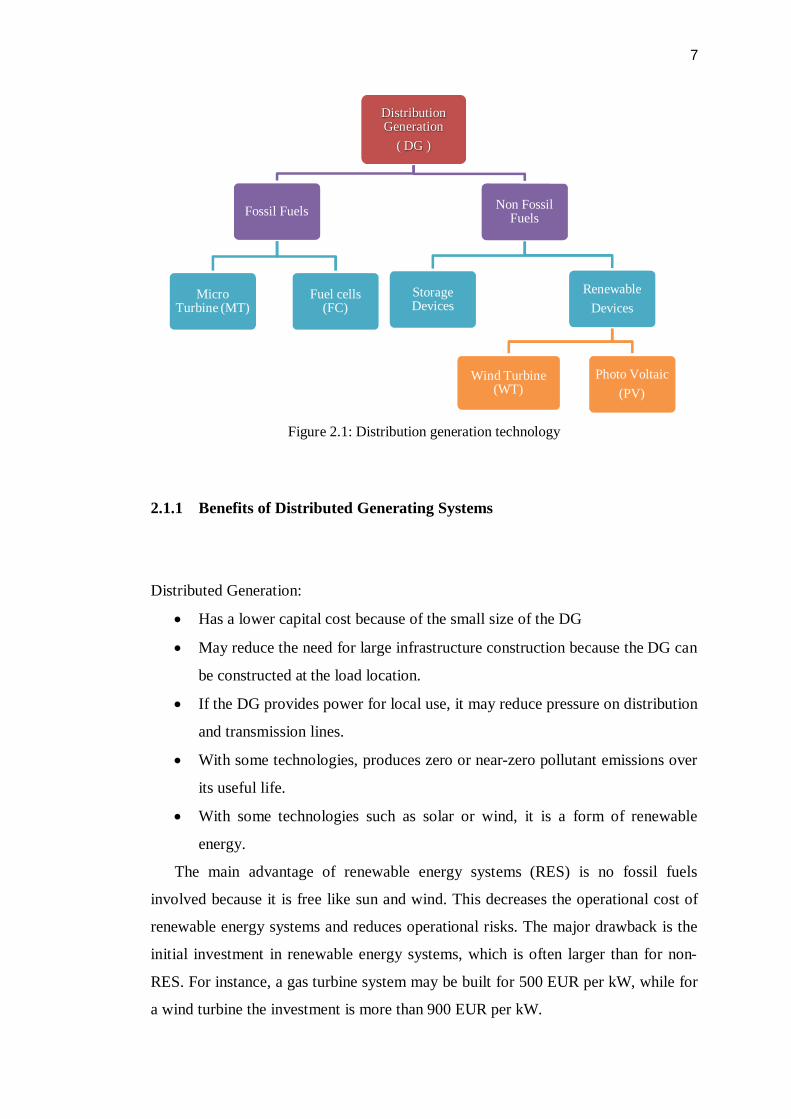
2.1 Distribution generation
Distribution generations (DG) are electric power generators that produce electricity
at a site close to customers or that are tied to an electric distribution system.
Distributed generators include, but are not limited to synchronous generators,
induction generators, reciprocating engines, micro turbines (combustion turbines that
run on high-energy fossil fuels such as oil, propane, natural gas, gasoline or diesel),
combustion gas turbines, fuel cells, solar photovoltaic, and wind turbines.
The concept of DG has been recently become commercially extensive.
distributed generation is the interconnection of alternative energy resources to the
utility grid system close to the load Point to mitigate the request for and expansion of
the electric transmission system [11]. DG is meant to shift the structure of the utility
system from a centralized, radial system to energy source connected on the
distribution level.
7
Figure 2.1: Distribution generation technology
2.1.1 Benefits of Distributed Generating Systems
Distributed Generation:
Has a lower capital cost because of the small size of the DG
May reduce the need for large infrastructure construction because the DG can
be constructed at the load location.
If the DG provides power for local use, it may reduce pressure on distribution
and transmission lines.
With some technologies, produces zero or near-zero pollutant emissions over
its useful life.
With some technologies such as solar or wind, it is a form of renewable
energy.
The main advantage of renewable energy systems (RES) is no fossil fuels
involved because it is free like sun and wind. This decreases the operational cost of
renewable energy systems and reduces operational risks. The major drawback is the
initial investment in renewable energy systems, which is often larger than for non-
RES. For instance, a gas turbine system may be built for 500 EUR per kW, while for
a wind turbine the investment is more than 900 EUR per kW.
Distribution Generation
( DG )
Fossil Fuels
Micro Turbine (MT)
Fuel cells (FC)
Non Fossil Fuels
Storage Devices
RenewableDevices
Wind Turbine (WT)
Photo Voltaic (PV)
8
Other disadvantages of RES are the specific requirements of the site and the
unpredictability of the power generated. The availability of renewable energy (sun,
wind, water) largely determines the feasibility of a renewable energy system and this
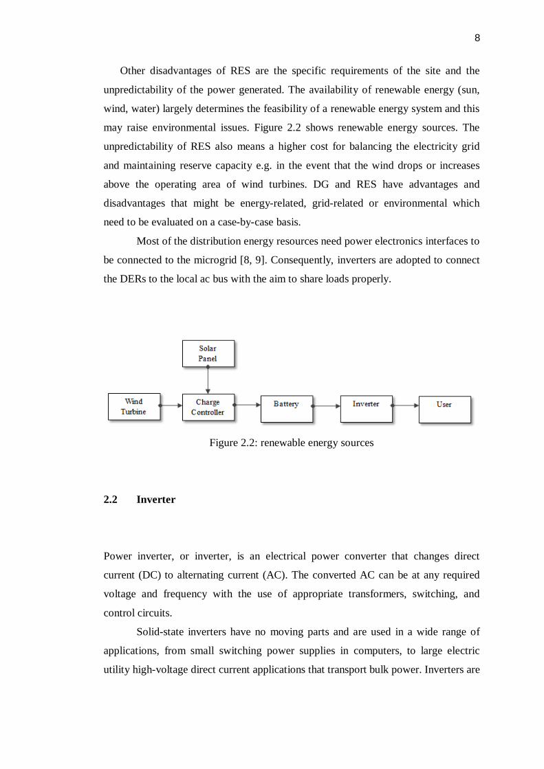
may raise environmental issues. Figure 2.2 shows renewable energy sources. The
unpredictability of RES also means a higher cost for balancing the electricity grid
and maintaining reserve capacity e.g. in the event that the wind drops or increases
above the operating area of wind turbines. DG and RES have advantages and
disadvantages that might be energy-related, grid-related or environmental which
need to be evaluated on a case-by-case basis.
Most of the distribution energy resources need power electronics interfaces to
be connected to the microgrid [8, 9]. Consequently, inverters are adopted to connect
the DERs to the local ac bus with the aim to share loads properly.
Figure 2.2: renewable energy sources
2.2 Inverter
Power inverter, or inverter, is an electrical power converter that changes direct
current (DC) to alternating current (AC). The converted AC can be at any required
voltage and frequency with the use of appropriate transformers, switching, and
control circuits.
Solid-state inverters have no moving parts and are used in a wide range of
applications, from small switching power supplies in computers, to large electric
utility high-voltage direct current applications that transport bulk power. Inverters are
9
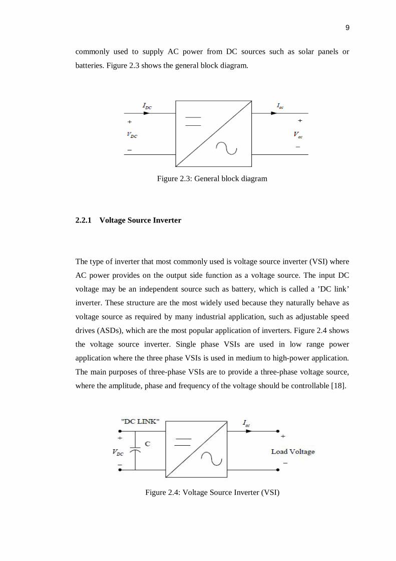
commonly used to supply AC power from DC sources such as solar panels or
batteries. Figure 2.3 shows the general block diagram.
Figure 2.3: General block diagram
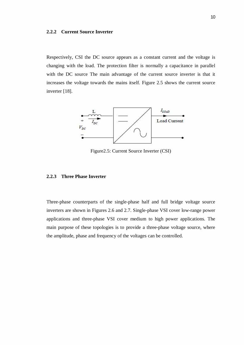
2.2.1 Voltage Source Inverter
The type of inverter that most commonly used is voltage source inverter (VSI) where
AC power provides on the output side function as a voltage source. The input DC
voltage may be an independent source such as battery, which is called a ’DC link’
inverter. These structure are the most widely used because they naturally behave as
voltage source as required by many industrial application, such as adjustable speed
drives (ASDs), which are the most popular application of inverters. Figure 2.4 shows
the voltage source inverter. Single phase VSIs are used in low range power
application where the three phase VSIs is used in medium to high-power application.
The main purposes of three-phase VSIs are to provide a three-phase voltage source,
where the amplitude, phase and frequency of the voltage should be controllable [18].
Figure 2.4: Voltage Source Inverter (VSI)
10
2.2.2 Current Source Inverter
Respectively, CSI the DC source appears as a constant current and the voltage is
changing with the load. The protection filter is normally a capacitance in parallel
with the DC source The main advantage of the current source inverter is that it
increases the voltage towards the mains itself. Figure 2.5 shows the current source
inverter [18].
Figure2.5: Current Source Inverter (CSI)
2.2.3 Three Phase Inverter
Three-phase counterparts of the single-phase half and full bridge voltage source
inverters are shown in Figures 2.6 and 2.7. Single-phase VSI cover low-range power
applications and three-phase VSI cover medium to high power applications. The
main purpose of these topologies is to provide a three-phase voltage source, where
the amplitude, phase and frequency of the voltages can be controlled.
11
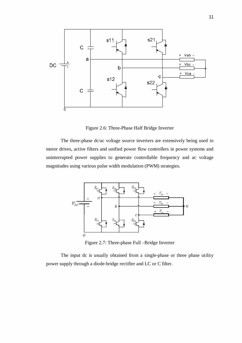
Figure 2.6: Three-Phase Half Bridge Inverter
The three-phase dc/ac voltage source inverters are extensively being used in
motor drives, active filters and unified power flow controllers in power systems and
uninterrupted power supplies to generate controllable frequency and ac voltage
magnitudes using various pulse width modulation (PWM) strategies.
Figure 2.7: Three-phase Full –Bridge Inverter
The input dc is usually obtained from a single-phase or three phase utility
power supply through a diode-bridge rectifier and LC or C filter.
12
2.3 Control of inverter
When interfacing distributed energy resources with the utility grid, a single inverter
can typically operate in two modes: one is the grid-connected mode and the other is
the isolated mode. Corresponding to these two modes, the controller has two distinct
modes of operation: power-control mode (PCM) and voltage-control mode (VCM)
[16].
2.3.1 PCM control
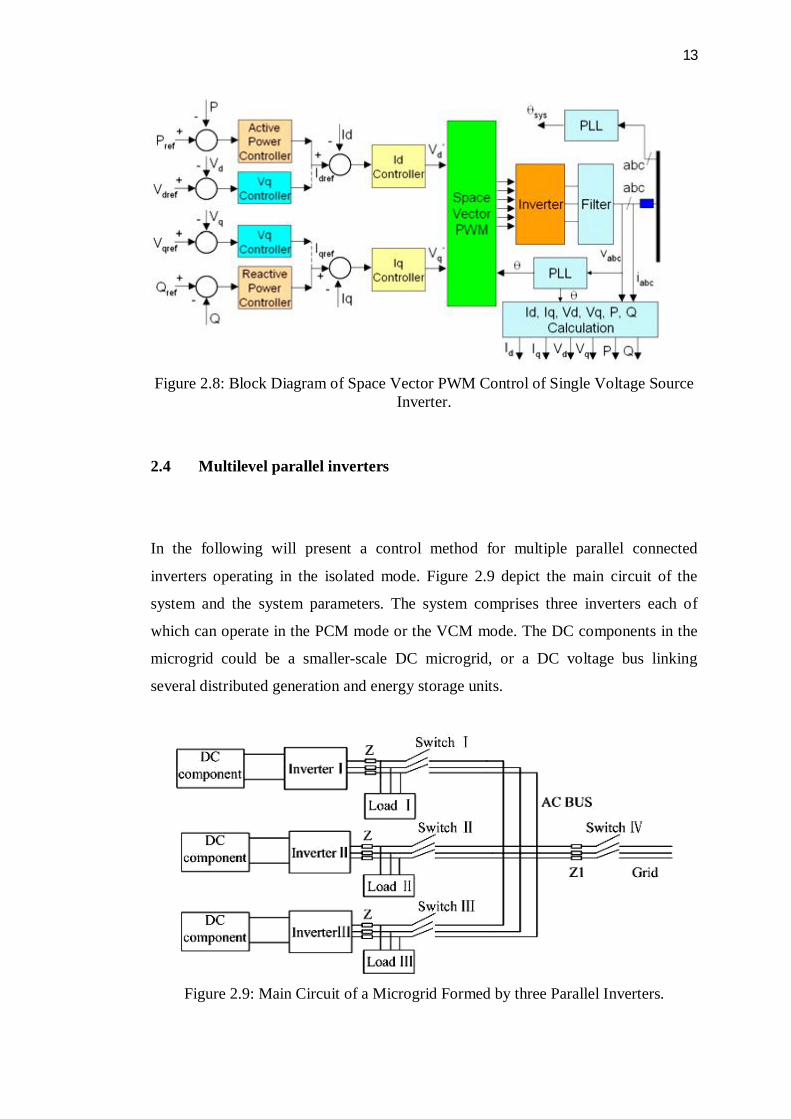
The grid-connected mode of operation requires that the power management system
(PMS) shall not actively regulate the voltage; hence the logical choice of control is a
form of current regulation. Here we use power flow control as a means of current
regulation. The control calculates current references for the system by the measured
voltage and desired power levels, as described in Figure 2.8, which shows the block
diagram of the power control system, where the current references are produced by
the outer power control loops.
2.3.2 VCM control
The isolated mode of operation requires the control operation to differ from that of
the grid-connected mode. In this mode, the system has already been disconnected
from the utility grid; therefore the voltage is no longer regulated by the grid. Because
of this, the control now needs to actively regulate the voltage of the local load, hence
a VCM control is o be used to regulate the output of the VSI. Figure 2.8 also shows a
block diagram of this control mode, where the current references are produced by the
inner voltage control loops.
13
Figure 2.8: Block Diagram of Space Vector PWM Control of Single Voltage Source
Inverter.
2.4 Multilevel parallel inverters
In the following will present a control method for multiple parallel connected
inverters operating in the isolated mode. Figure 2.9 depict the main circuit of the
system and the system parameters. The system comprises three inverters each of
which can operate in the PCM mode or the VCM mode. The DC components in the
microgrid could be a smaller-scale DC microgrid, or a DC voltage bus linking
several distributed generation and energy storage units.
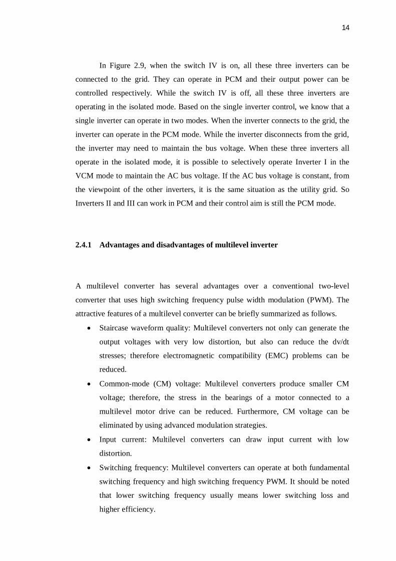
Figure 2.9: Main Circuit of a Microgrid Formed by three Parallel Inverters.
14
In Figure 2.9, when the switch IV is on, all these three inverters can be
connected to the grid. They can operate in PCM and their output power can be
controlled respectively. While the switch IV is off, all these three inverters are
operating in the isolated mode. Based on the single inverter control, we know that a
single inverter can operate in two modes. When the inverter connects to the grid, the
inverter can operate in the PCM mode. While the inverter disconnects from the grid,
the inverter may need to maintain the bus voltage. When these three inverters all
operate in the isolated mode, it is possible to selectively operate Inverter I in the
VCM mode to maintain the AC bus voltage. If the AC bus voltage is constant, from
the viewpoint of the other inverters, it is the same situation as the utility grid. So
Inverters II and III can work in PCM and their control aim is still the PCM mode.
2.4.1 Advantages and disadvantages of multilevel inverter
A multilevel converter has several advantages over a conventional two-level
converter that uses high switching frequency pulse width modulation (PWM). The
attractive features of a multilevel converter can be briefly summarized as follows.
Staircase waveform quality: Multilevel converters not only can generate the
output voltages with very low distortion, but also can reduce the dv/dt
stresses; therefore electromagnetic compatibility (EMC) problems can be
reduced.
Common-mode (CM) voltage: Multilevel converters produce smaller CM
voltage; therefore, the stress in the bearings of a motor connected to a
multilevel motor drive can be reduced. Furthermore, CM voltage can be
eliminated by using advanced modulation strategies.
Input current: Multilevel converters can draw input current with low
distortion.
Switching frequency: Multilevel converters can operate at both fundamental
switching frequency and high switching frequency PWM. It should be noted
that lower switching frequency usually means lower switching loss and
higher efficiency.
15
One particular disadvantage is the greater number of power semiconductor
switches needed. This may cause the overall system to be more expensive and
complex
2.5 Control system
A control system is a device or set of devices to manage, command, direct or regulate
the behaviour of other devices or systems. A control mechanism is a process used by
a control system. There are many controller systems user in the inverter controller
such as PI controller, PID controller and droop controller.
2.5.1 PI control
PI controller is proposed is to improve the performance of the soft switched inverter.
The duty ratio of the inverter is controlled by PI controller. To provide optimal
performance at all operating conditions of the system PI controller is developed to
control the duty ratio of the inverter.
PI control is a traditional linear control method used in industrial
applications. The linear PI controller controllers are usually designed for dc-ac
inverter and dc-dc converters using standard frequency response techniques and
based on the small signal model of the converter. A Bode plot is used in the design to
obtain the desired loop gain, crossover frequency and phase margin. The stability of
the system is guaranteed by an adequate phase margin. However, linear PID and PI
controllers can only be designed for one nominal operating point. A boost
converter’s small signal Model changes when the operating point varies. The poles
and a right-half plane zero, as well as the magnitude of the frequency response, are
all dependent on the duty cycle. Therefore, it is difficult for the PID controller to
respond well to changes in operating point. The PI controller is designed for the
boost converter for operation during a start-up transient and steady state respectively
[15].
16
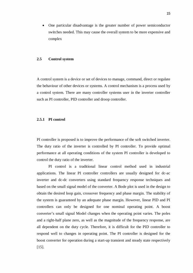
Figure 2.10 Block diagram of the PI controller.
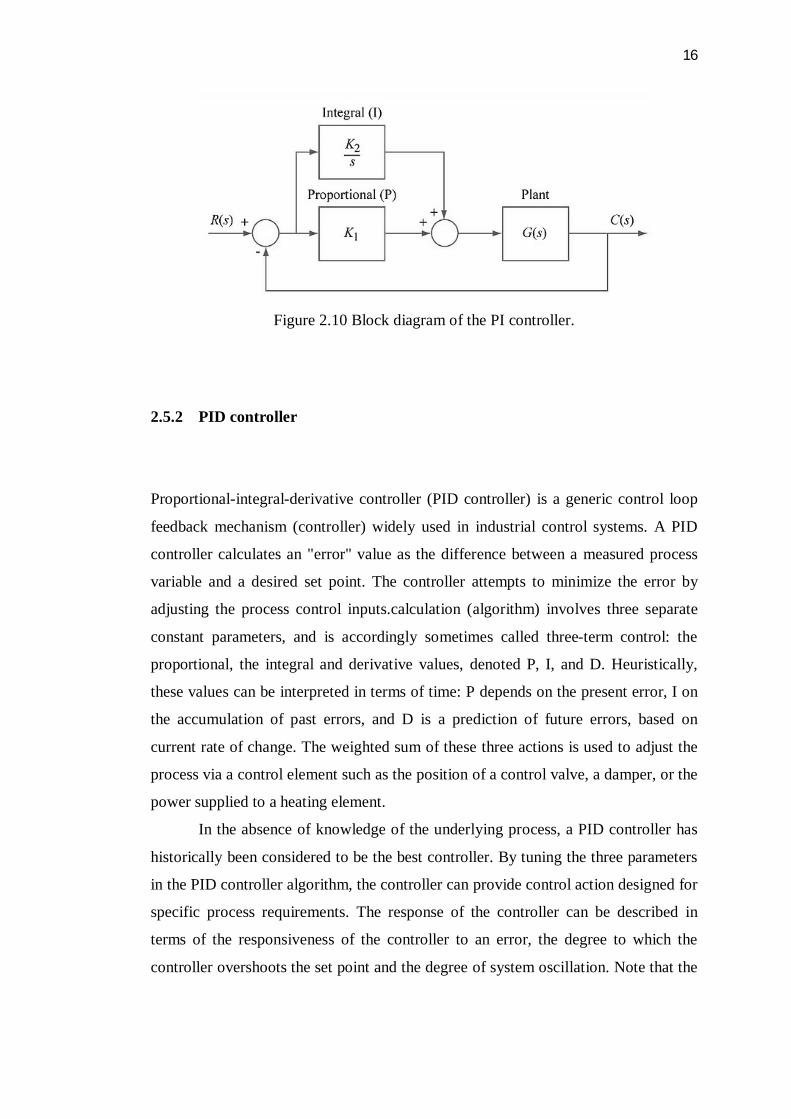
2.5.2 PID controller
Proportional-integral-derivative controller (PID controller) is a generic control loop
feedback mechanism (controller) widely used in industrial control systems. A PID
controller calculates an "error" value as the difference between a measured process
variable and a desired set point. The controller attempts to minimize the error by
adjusting the process control inputs.calculation (algorithm) involves three separate
constant parameters, and is accordingly sometimes called three-term control: the
proportional, the integral and derivative values, denoted P, I, and D. Heuristically,
these values can be interpreted in terms of time: P depends on the present error, I on
the accumulation of past errors, and D is a prediction of future errors, based on
current rate of change. The weighted sum of these three actions is used to adjust the
process via a control element such as the position of a control valve, a damper, or the
power supplied to a heating element.
In the absence of knowledge of the underlying process, a PID controller has
historically been considered to be the best controller. By tuning the three parameters
in the PID controller algorithm, the controller can provide control action designed for
specific process requirements. The response of the controller can be described in
terms of the responsiveness of the controller to an error, the degree to which the
controller overshoots the set point and the degree of system oscillation. Note that the
17
use of the PID algorithm for control does not guarantee optimal control of the system
or system stability.
Figure2.11: A block diagram of a PID controller in a feedback loop
2.6 Droop control
Droop control strategy is proposed to enhance the dynamic performance of the
parallel inverters in microgrids without communication wire interconnections. A
wireless controller is developed by taking the active and reactive current as the
control variables, the droop control variables is taken to ensure the power sharing
accuracy, and additional terms are added to the droop controller to enhance the
dynamic performance.
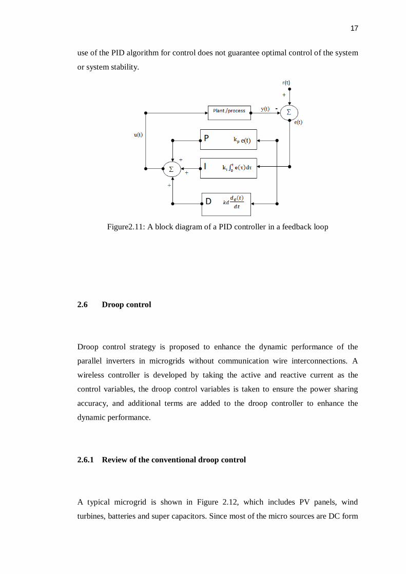
2.6.1 Review of the conventional droop control
A typical microgrid is shown in Figure 2.12, which includes PV panels, wind
turbines, batteries and super capacitors. Since most of the micro sources are DC form
18
or need to be converted to DC form first, voltage source inverters are used for each
of the micro sources. The inverters can be modelled as a voltage source connected to
the ac bus through complex impedance, as shown in Figure 2.13
Figure 2.12: Typical Microgrid Diagram [17]
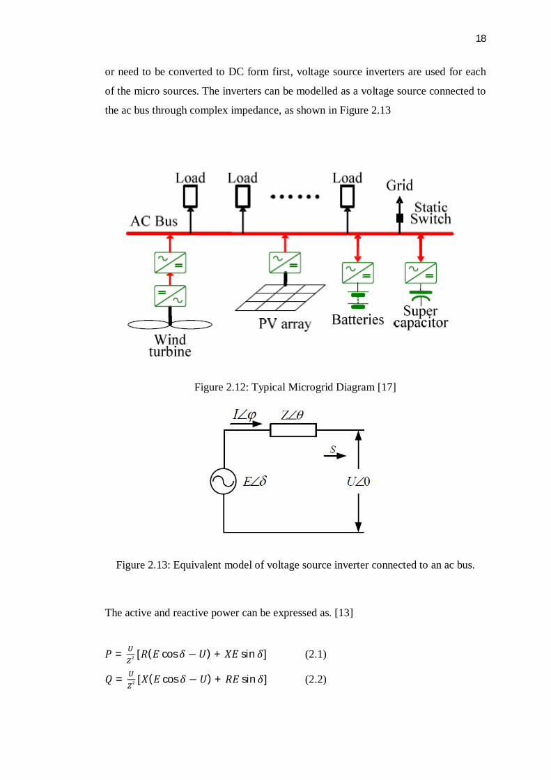
Figure 2.13: Equivalent model of voltage source inverter connected to an ac bus.
The active and reactive power can be expressed as. [13]
푃 = ² [푅(퐸 cos훿 − 푈) + 푋퐸 sin 훿] (2.1)
푄 = ² [푋(퐸 cos훿 − 푈) + 푅퐸 sin훿] (2.2)
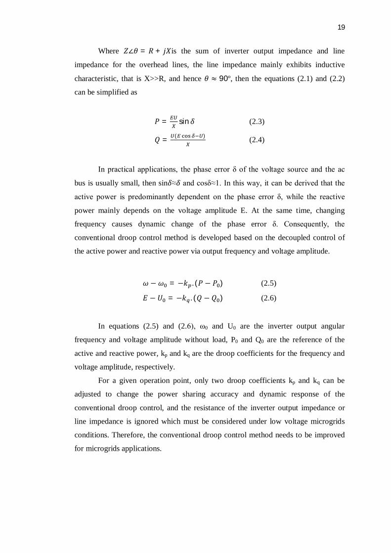
19
Where 푍∠휃 = 푅 + 푗푋is the sum of inverter output impedance and line
impedance for the overhead lines, the line impedance mainly exhibits inductive
characteristic, that is X>>R, and hence 휃 ≈ 90º, then the equations (2.1) and (2.2)
can be simplified as
푃 = sin훿 (2.3)
푄 = ( ) (2.4)
In practical applications, the phase error δ of the voltage source and the ac
bus is usually small, then sin훿≈훿 and cosδ≈1. In this way, it can be derived that the
active power is predominantly dependent on the phase error δ, while the reactive
power mainly depends on the voltage amplitude E. At the same time, changing
frequency causes dynamic change of the phase error δ. Consequently, the
conventional droop control method is developed based on the decoupled control of
the active power and reactive power via output frequency and voltage amplitude.
휔 − 휔 = −푘 . (푃 − 푃 ) (2.5)
퐸 − 푈 = −푘 . (푄 − 푄 ) (2.6)
In equations (2.5) and (2.6), ω0 and U0 are the inverter output angular
frequency and voltage amplitude without load, P0 and Q0 are the reference of the
active and reactive power, kp and kq are the droop coefficients for the frequency and
voltage amplitude, respectively.
For a given operation point, only two droop coefficients kp and kq can be
adjusted to change the power sharing accuracy and dynamic response of the
conventional droop control, and the resistance of the inverter output impedance or
line impedance is ignored which must be considered under low voltage microgrids
conditions. Therefore, the conventional droop control method needs to be improved
for microgrids applications.
20
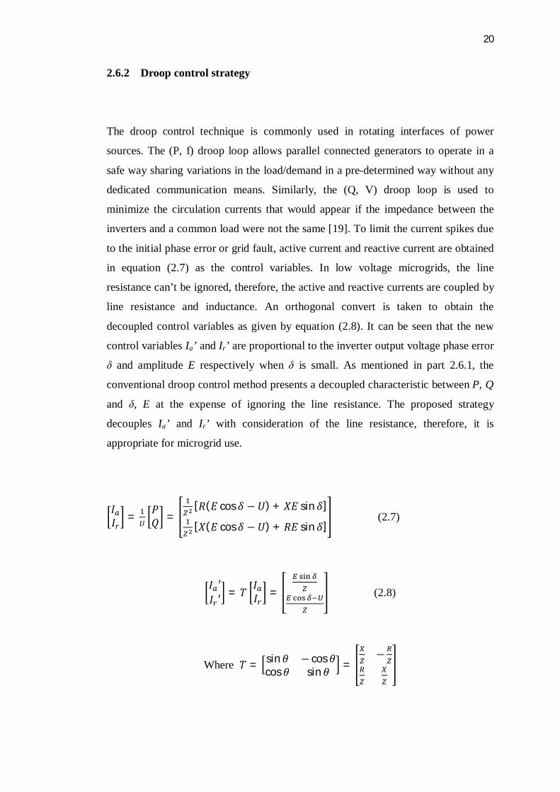
2.6.2 Droop control strategy
The droop control technique is commonly used in rotating interfaces of power
sources. The (P, f) droop loop allows parallel connected generators to operate in a
safe way sharing variations in the load/demand in a pre-determined way without any
dedicated communication means. Similarly, the (Q, V) droop loop is used to
minimize the circulation currents that would appear if the impedance between the
inverters and a common load were not the same [19]. To limit the current spikes due
to the initial phase error or grid fault, active current and reactive current are obtained
in equation (2.7) as the control variables. In low voltage microgrids, the line
resistance can’t be ignored, therefore, the active and reactive currents are coupled by
line resistance and inductance. An orthogonal convert is taken to obtain the
decoupled control variables as given by equation (2.8). It can be seen that the new
control variables Ia’ and Ir’ are proportional to the inverter output voltage phase error
δ and amplitude E respectively when δ is small. As mentioned in part 2.6.1, the
conventional droop control method presents a decoupled characteristic between P, Q
and δ, E at the expense of ignoring the line resistance. The proposed strategy
decouples Ia’ and Ir’ with consideration of the line resistance, therefore, it is
appropriate for microgrid use.
퐼퐼 = 푃
푄 =[푅(퐸 cos 훿 − 푈) + 푋퐸 sin훿]
[푋(퐸 cos훿 − 푈) + 푅퐸 sin훿] (2.7)
퐼 ′퐼 ′ = 푇 퐼
퐼 = (2.8)
Where 푇 = sin휃 − cos 휃cos 휃 sin휃 =
−
21
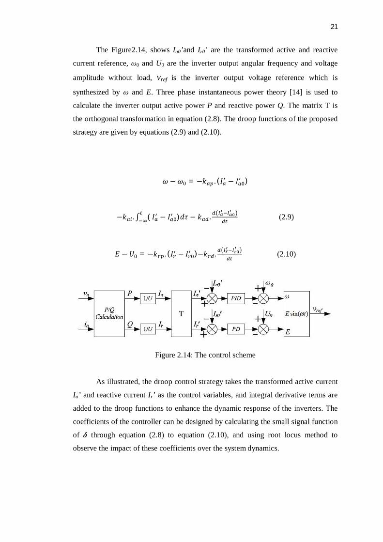
The Figure2.14, shows Ia0’and Ir0’ are the transformed active and reactive
current reference, ω0 and U0 are the inverter output angular frequency and voltage
amplitude without load, vref is the inverter output voltage reference which is
synthesized by ω and E. Three phase instantaneous power theory [14] is used to
calculate the inverter output active power P and reactive power Q. The matrix T is
the orthogonal transformation in equation (2.8). The droop functions of the proposed
strategy are given by equations (2.9) and (2.10).
휔 −휔 = −푘 . (퐼 − 퐼 )
−푘 .∫ ( 퐼 − 퐼 )푑휏 − 푘 . (2.9)
퐸 − 푈 = −푘 . (퐼 − 퐼 )−푘 . (2.10)
Figure 2.14: The control scheme
As illustrated, the droop control strategy takes the transformed active current
Ia’ and reactive current Ir’ as the control variables, and integral derivative terms are
added to the droop functions to enhance the dynamic response of the inverters. The
coefficients of the controller can be designed by calculating the small signal function
of δ through equation (2.8) to equation (2.10), and using root locus method to
observe the impact of these coefficients over the system dynamics.
22
Uabc
Vdc
Ia &Ircalculation
iabc
C
L
Droop controlPMW
w
E
Ia
Ir
To the AC bus
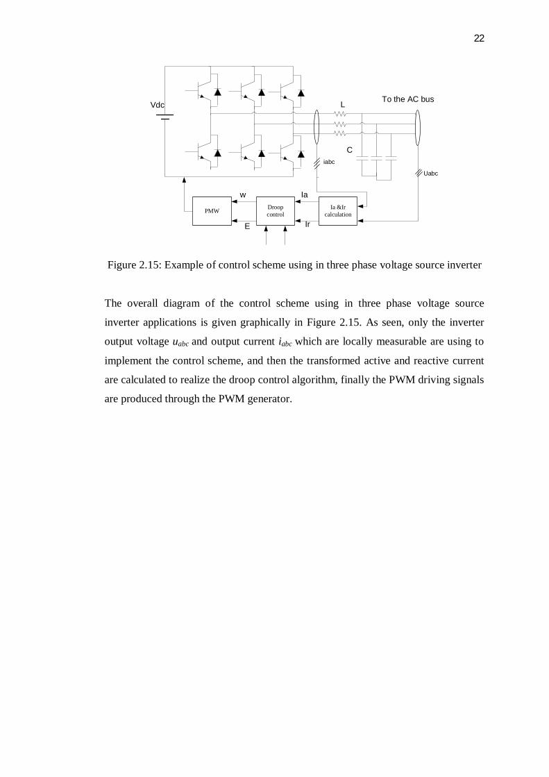
Figure 2.15: Example of control scheme using in three phase voltage source inverter
The overall diagram of the control scheme using in three phase voltage source
inverter applications is given graphically in Figure 2.15. As seen, only the inverter
output voltage uabc and output current iabc which are locally measurable are using to
implement the control scheme, and then the transformed active and reactive current
are calculated to realize the droop control algorithm, finally the PWM driving signals
are produced through the PWM generator.
23
CHAPTER 3
METHODOLOGY
3.1 Introduction
In this chapter, it presents the block diagram and the flow chart of this project. Also
it will prove the equation for droop controller to share the loading for two parallel
inverters.
3.2 Droop control
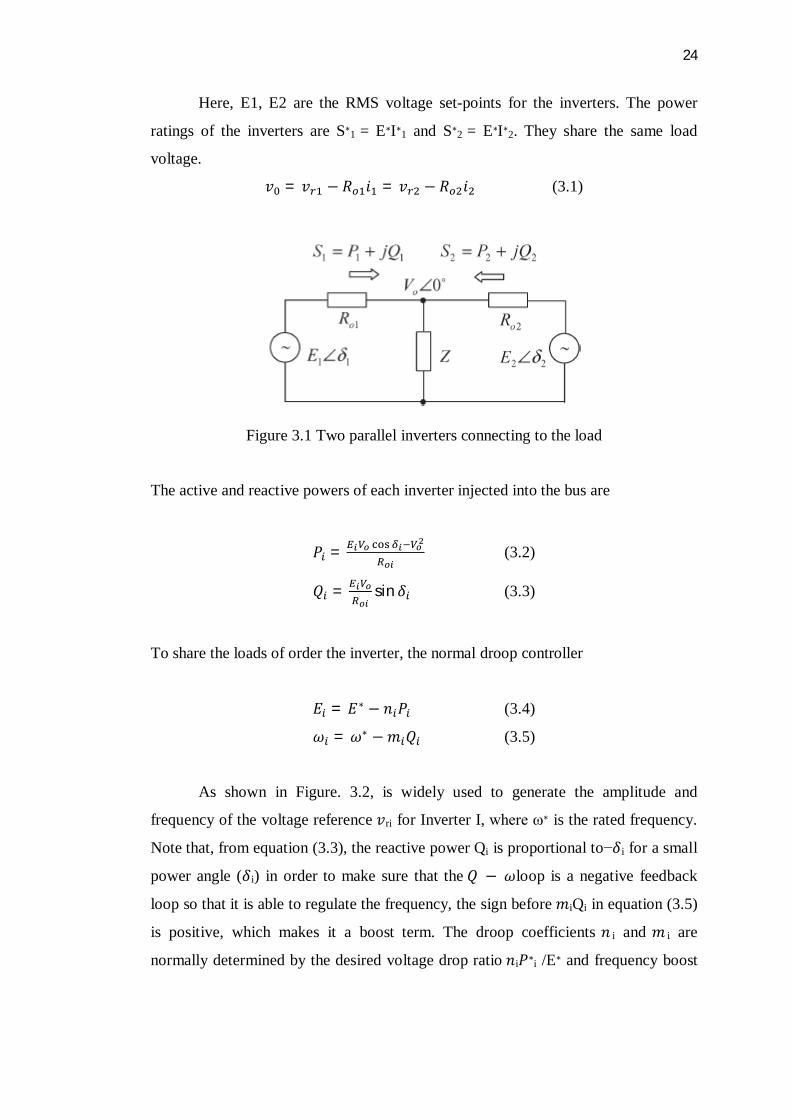
The analysis will be done for the Q − ω and P − E droop. The sketch of two inverters
with resistive output impedances Ro1 and Ro2 operated in parallel is shown in Figure.
3.1. The line impedances are omitted because the output impedances of the inverters
can be designed to dominate the impedance from the inverter to the ac-bus. The
reference voltages of the two inverters are, respectively
푣 = √2퐸 sin(휔 + 훿 )
푣 = √2퐸 sin(휔 + 훿 )
24
Here, E1, E2 are the RMS voltage set-points for the inverters. The power
ratings of the inverters are S∗1 = E∗I∗1 and S∗2 = E∗I∗2. They share the same load
voltage.
푣 = 푣 − 푅 푖 = 푣 − 푅 푖 (3.1)
Figure 3.1 Two parallel inverters connecting to the load
The active and reactive powers of each inverter injected into the bus are
푃 = (3.2)
푄 = sin훿 (3.3)
To share the loads of order the inverter, the normal droop controller
퐸 = 퐸∗ − 푛 푃 (3.4)
휔 = 휔∗ −푚 푄 (3.5)
As shown in Figure. 3.2, is widely used to generate the amplitude and
frequency of the voltage reference 푣ri for Inverter I, where ω∗ is the rated frequency.
Note that, from equation (3.3), the reactive power Qi is proportional to−훿i for a small
power angle (훿i) in order to make sure that the 푄 − 휔loop is a negative feedback
loop so that it is able to regulate the frequency, the sign before 푚iQi in equation (3.5)
is positive, which makes it a boost term. The droop coefficients 푛 i and 푚 i are
normally determined by the desired voltage drop ratio 푛i푃∗i /E∗ and frequency boost
49
REFERENCES
[1]. IEEE Standard for Interconnecting Distributed Resources With Electric Power
Systems, IEEE Standard 1547-2003, 2003
[2]. P.L.Villeneuve, “Concerns generated by islanding,” IEEE Power
& Energy Magazine, May/June 2004, pp. 49-53
[3]. Godoy, Ruben Barros, et al. "Differential-evolution-based optimization of the
dynamic response for parallel operation of inverters with no controller
interconnection." Industrial Electronics, IEEE Transactions on 59.7 (2012): 2859-
2866.
[4]. Rocabert, Joan, et al. "Control of power converters in AC microgrids." Power
Electronics, IEEE Transactions on 27.11 (2012): 4734-4749.
[5]. R. Teodorescu and F. Blaabjerg, “Flexible control of small wind turbines with grid
failure detection operating in stand-alone and grid-connected mode,” IEEE Trans.
Power Electron., vol. 9, no. 5, Sept. 2004, pp 1323-1332.
[6]. López, Mariano, et al. "Current distribution control design for paralleled DC/DC
converters using sliding-mode control." Industrial Electronics, IEEE Transactions on
51.2 (2004): 419-428.
[7]. Guerrero, Josep M., Lijun Hang, and Javier Uceda. "Control of distributed
uninterruptible power supply systems." Industrial Electronics, IEEE Transactions on
55.8 (2008): 2845-2859.
[8]. J. M. Carrasco, et al., "Power-Electronic Systems for the Grid Integration of
Renewable Energy Sources: A Survey," Industrial Electronics, IEEE Transactions on,
vol. 53, pp. 1002-1016, 2006.
[9]. F. Blaabjerg, et al., "Overview of Control and Grid Synchronization for Distributed
Power Generation Systems," Industrial Electronics, IEEE Transactions on, vol. 53,
pp. 1398-1409, 2006.
50
[10]. E. Barklund, et al., "Energy Management in Autonomous Microgrid Using Stability-
Constrained Droop Control of Inverters," Power Electronics, IEEE Transactions on,
vol. 23, pp. 2346-2352, 2008.
[11]. Younis, M. A. A., N. A. Rahim, and S. Mekhilef. "Distributed generation with
parallel connected inverter." Industrial Electronics and Applications, 2009. ICIEA
2009. 4th IEEE Conference on. IEEE, 2009.
[12]. Mohr, Malte, and Friedrich W. Fuchs. "Comparison of three phase current source
inverters and voltage source inverters linked with DC to DC boost converters for fuel
cell generation systems." Power Electronics and Applications, 2005 European
Conference on. IEEE, 2005.
[13]. Chung, Il-Yop, et al. "Control methods of inverter-interfaced distributed generators
in a microgrid system." Industry Applications, IEEE Transactions on 46.3 (2010):
1078-1088.
[14]. Hu, Jie Feng, Jian Guo Zhu, and Glenn Platt. "A droop control strategy of parallel-
inverter-based microgrid." Applied Superconductivity and Electromagnetic Devices
(ASEMD), 2011 International Conference on. IEEE, 2011.
[15]. Ortega, R., et al. "A PI-P+ Resonant controller design for single phase inverter
operating in isolated microgrids." Industrial Electronics (ISIE), 2012 IEEE
International Symposium on. IEEE, 2012.
[16]. Yu, Xunwei, Zhenhua Jiang, and Yu Zhang. "Control of parallel inverter-interfaced
distributed energy resources." Energy 2030 Conference, 2008. ENERGY 2008.
IEEE. IEEE, 2008.
[17]. Liu, Quanwei, et al. "Droop control for parallel inverters in microgrids." Power
Electronics and Motion Control Conference (IPEMC), 2012 7th International. Vol. 3.
IEEE, 2012.
[18]. Salam, Zainal, Abdul Aziz, and MohdJunaidi. "The Design and Development of a
High Perfomance Bi-directional Inverter For Photovoltaic Application." (2003).
[19]. Simpson-Porco, John W., Florian Dörfler, and Francesco Bullo. "Droop-controlled
inverters in microgrids are Kuramoto oscillators." IFAC Workshop on Distributed
Estimation and Control in Networked Systems, Santa Barbara, CA, USA. 2012.
[20]. MOAWWAD, Ahmed, Vinod KHADKIKAR, and James L. KIRTLEY. "A New
PQV Droop Control Method for an Interline Photovoltaic (I-PV) Power System."
IEEE transactions on power delivery 28.2 (2013): 658-668.