metering, telemetry, and curtailment requirements for
TRANSCRIPT

4/29/2020
Metering, Telemetry, and Curtailment Requirements for Distributed Energy Resources
2 Revision 10
Contents Disclaimer ..................................................................................................................................... 3
Purpose ......................................................................................................................................... 3
Definitions ..................................................................................................................................... 3
General Requirements .................................................................................................................. 4
Method 1 ................................................................................................................................... 4
Method 2 ................................................................................................................................... 5
Method 3 ................................................................................................................................... 5
Project Specific Requirements ...................................................................................................... 5
Metering and Real-Time Telemetry Data Requirements ........................................................... 6
Transmission Provider Requirements ........................................................................................ 8
Project Costs .............................................................................................................................. 8
Information Timeline .................................................................................................................... 9
Interconnection Agreement Execution ................................................................................. 9
Project Construction ............................................................................................................. 9
Project Commissioning .......................................................................................................... 9
Revision History .......................................................................................................................... 11
Attachment 1 – Communications Diagram ................................................................................. 12
Attachment 2 – NCEMC Communication Cabinet Specifications ................................................ 13
Attachment 3 – Fiber Converter Specifications ........................................................................... 14
Attachment 4 – MV-90 Supported Meters .................................................................................. 15
Attachment 5 – Draft Metering and Telemetry Requirements Letter ......................................... 16
Attachment 6 – Metering and Real-Time Data Specifications ..................................................... 17
3 Revision 10
Disclaimer The requirements set out in this standard are revised from time to time to reflect changes in technology, regulation, and business practices. As such, the requirements for a Seller’s particular project will be memorialized in one of the following two ways:
(1) Where the requirements for a Seller’s particular project have been identified and agreed to prior to execution of the Seller’s Power Purchase Agreement (PPA), the requirements for the particular project will be incorporated into the PPA, via an exhibit to the PPA.
(2) Where the requirements for a Seller’s particular project cannot be identified prior to execution of the Seller’s PPA, this standard, including this disclaimer, will be attached as a placeholder exhibit to the PPA; NCEMC and Seller shall thereafter work in good faith to execute a letter agreement – in the form set out in Attachment 5 to this standard – that sets out the requirements for the particular project.
Purpose This document provides North Carolina Electric Membership Corporation (NCEMC)’s requirements for metering, real-time telemetry data, and curtailment for Utility Distributed Energy Resources (UDER) interconnected to the system of a NCEMC Member. These requirements refer to all UDER regardless of its Qualifying Facility (QF) status and the purchaser of generation from the site. These requirements are in place to ensure the receipt of accurate and timely data for accounting and billing of resources under an executed PPA with NCEMC or NCEMC Member, and real time telemetry data integration into the NCEMC Energy Management System (EMS) and/or Distributed Energy Resources Management System (DERMS) for situational awareness, daily system operations, load modeling, reporting, and forecasting. These requirements are also intended to ensure that proper communications equipment is in place to curtail generation to preserve grid reliability.
Definitions Interconnection Agreement - The agreement that identifies the conditions under which the Seller’s generation system and equipment, will interconnect with, and operate in parallel with the NCEMC Member's electric power system.
Meter – Revenue quality metering equipment that is installed and tested in accordance with applicable American National Standards Institute (ANSI) standards and all applicable regulatory requirements to provide billing information as part of the PPA. This equipment may also be used to provide telemetry data.
Non-Utility DER – DERs that offset customer load, including residential, commercial, and industrial customers, limited to no more than 50 kW. Point of Delivery - Point(s) on the Transmission Provider's System where capacity and energy transmitted by the Transmission Provider is delivered to the NCEMC Member.
4 Revision 10
Point of Interconnection – The point where the Seller’s facilities connect with the NCEMC Member's electric power system as outlined in the applicable Interconnection Agreement.
Power Purchase Agreement (PPA) – The agreement that identifies the terms and conditions under which the Seller will sell the output of the generation system to NCEMC or an NCEMC Member.
Qualifying Facility (QF) – A generator or generation system that meets the requirements of the Public Utility Regulatory Policies Act (PURPA) for certification as a QF. Seller – Any party that has entered into a Power Purchase Agreement with NCEMC or an NCEMC Member to sell the output of the UDER. Utility DER – DERs that either:
• Directly connect to, or closely connected to, the distribution bus or connected to the distribution bus through a dedicated, non-load serving feeder;
• DER that offset customer load, but greater than 50 kW; • Community DERs that do not serve any load directly but are interconnected to a
single-phase or three phase distribution load serving feeder.
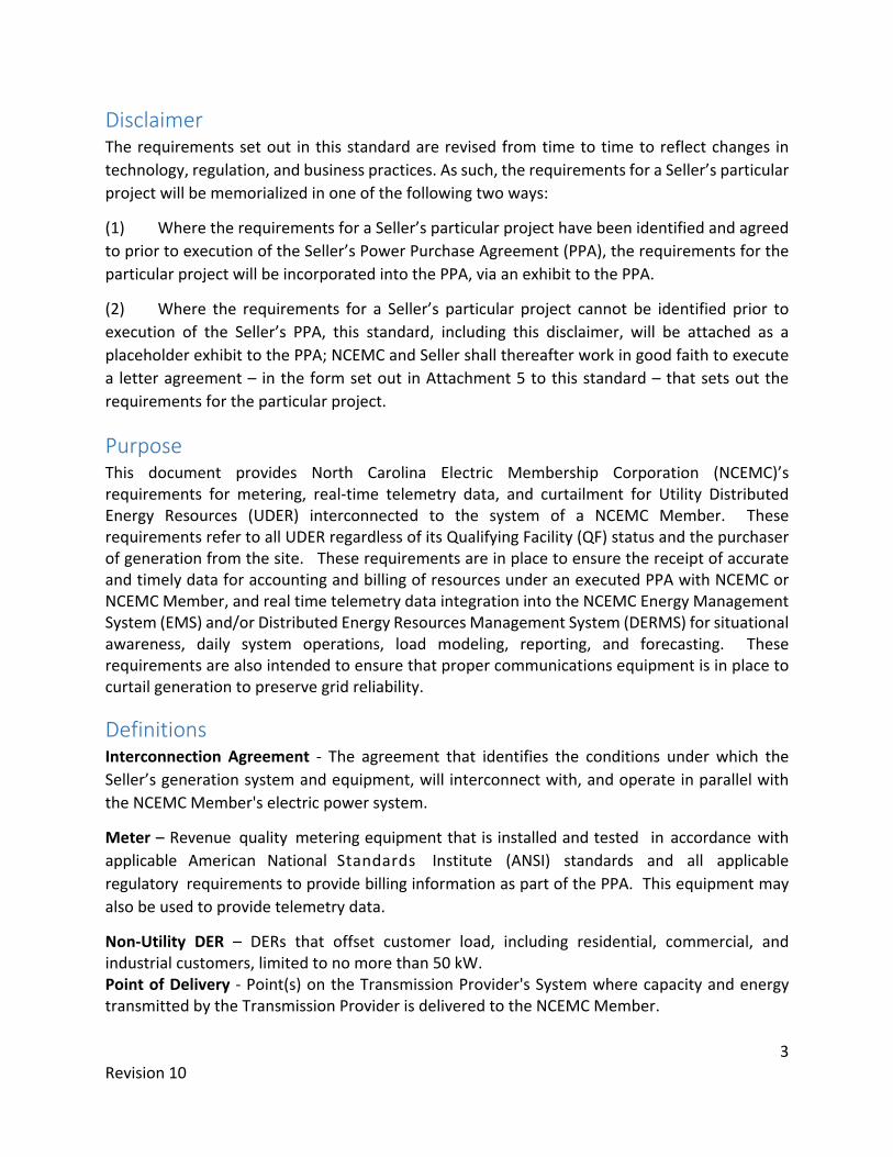
General Requirements • A Meter shall be installed at the Point of Interconnection as shown in the diagrams below. • NCEMC's purchase of energy (generation) under the PPA and the NCEMC Member’s retail
sales of energy (site auxiliary load) to the UDER may be metered separately. • Locations with multiple generators operating under separate PPAs at a single Point of
Interconnection will require separate metering for each PPA.
Method 1
Figure 1 – Seller Owned Meter

5 Revision 10
Method 2
Figure 2 – Co-op Owned Single Meter Configuration
Method 3
Figure 3 – Co-op Owned Dual Meter Configuration
Meters installed on the low-side of the transformer will have a compensation value programmed in the meter to account for the transformer losses. All metering PT/CTs installed shall be revenue grade with an accuracy class of 0.3% or better.
Project Specific Requirements The following requirements assume the Seller will own, install, and maintain the Meter. The Seller may arrange for NCEMC’s Member instead own, install and maintain the Meter, but in such circumstances, these requirements remain applicable.
6 Revision 10
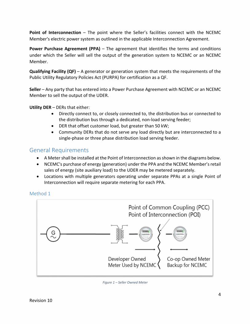
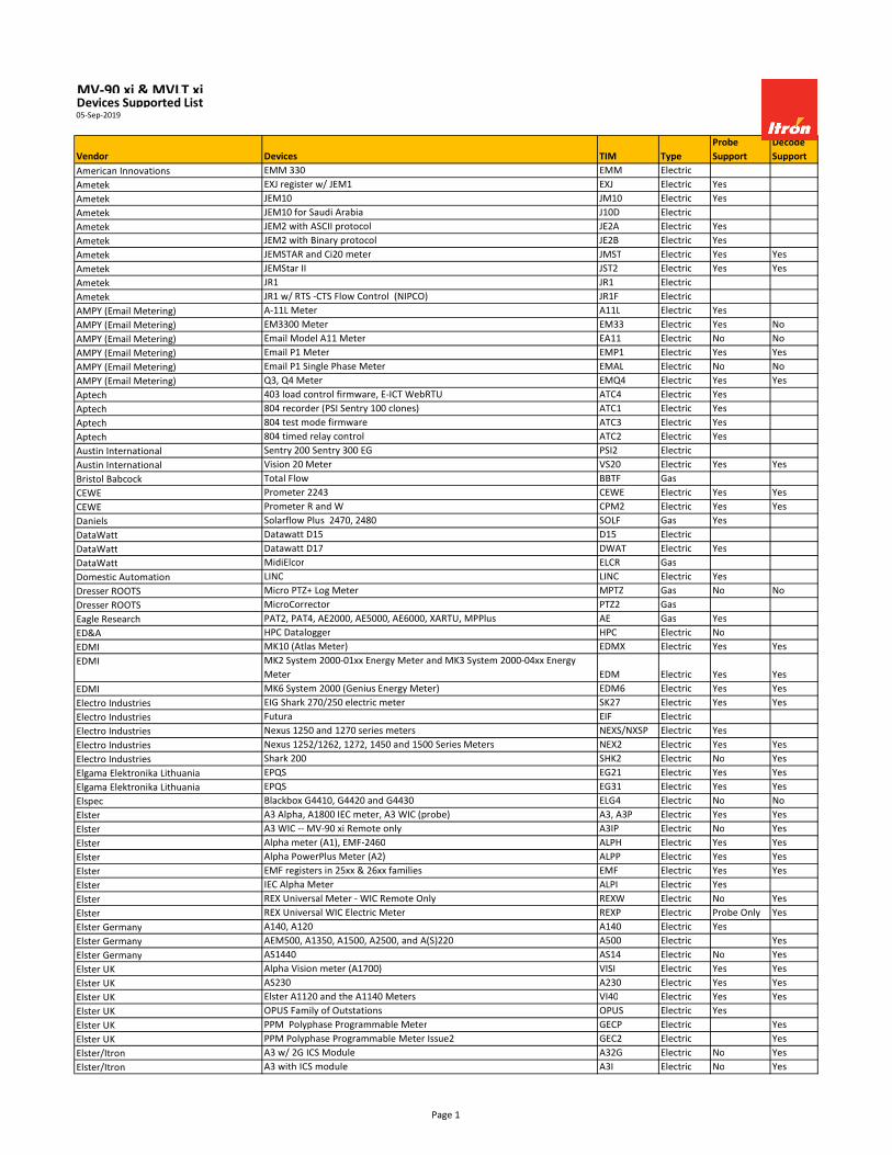
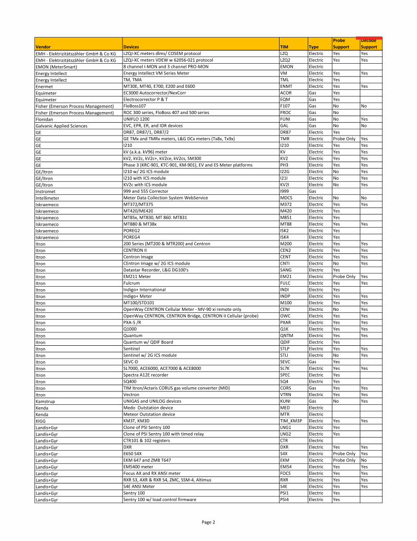
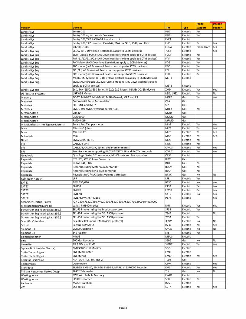
Metering and Real-Time Telemetry Data Requirements 1. Seller will install an MV-90 compatible Meter to be used by NCEMC for accounting and
billing purposes where NCEMC has the PPA. Attachment 4 contains a list of acceptable meters that is not all inclusive. To satisfy this metering requirement, NCEMC recommends the following based on the UDER size:
UDER Size Recommended Meter
Notes
< 250 kW • Aclara kV2C • Elster A3RAL
None
≥ 250 kW • SEL - 735 Enables delivery of billing and real-time data from a single meter, while also meeting power quality monitoring requirements
The Meter shall be installed so that generation from the site is shown as positive kW on the real-time telemetry at the point of interconnection defined in the Interconnection Agreement between the NCEMC Member and the Seller. Any Metering PT/CTs that are installed to meter the output of the site shall be revenue grade with an accuracy class of 0.3% or better. In the case that metering equipment is installed on the low side of the step-up transformer, compensation to reflect the losses associated with the transformer shall be programmed into the meter.
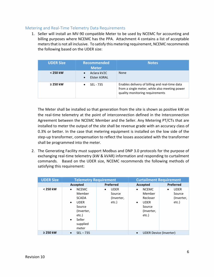
2. The Generating Facility must support Modbus and DNP 3.0 protocols for the purpose of exchanging real-time telemetry (kW & kVAR) information and responding to curtailment commands. Based on the UDER size, NCEMC recommends the following methods of satisfying this requirement:
UDER Size Telemetry Requirement Curtailment Requirement Accepted Preferred Accepted Preferred
< 250 kW • NCEMC Member SCADA
• UDER Source (Inverter, etc.)
• Seller supplied meter
• UDER Source (Inverter, etc.)
• NCEMC Member Recloser
• UDER Source (Inverter, etc.)
• UDER Source (Inverter, etc.)
≥ 250 kW • SEL – 735 • UDER Device (Inverter)

7 Revision 10
3. Seller will make the following data available to NCEMC through a dedicated Ethernet connection: a. MV-90 protocol will be utilized by NCEMC for interrogation of the meter on site for
billing purposes (kWh). The Meter will be programmed for Eastern Standard Time. b. DNP 3.0 protocol to be utilized by NCEMC for real-time data transmittal (kW & kVAR).
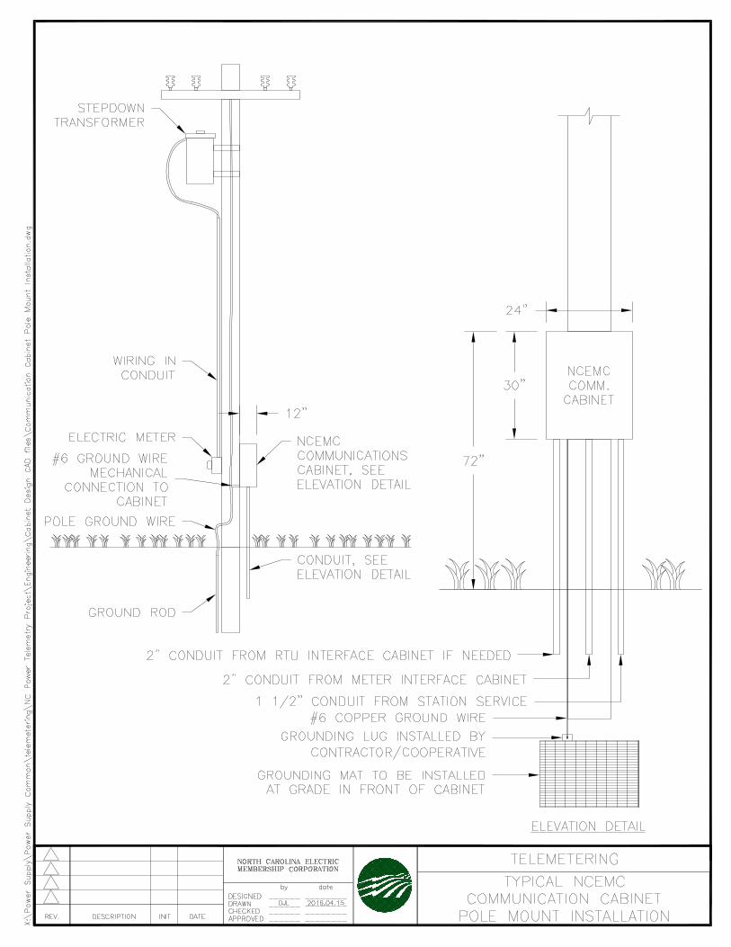
4. Seller will procure a Hoffman A30H2412GQRLP fiberglass cabinet (“NCEMC Communication Cabinet”) and A30P24 Subpanel. The Seller may propose an alternative box to NCEMC for consideration; this box shall be similar in size, construction, material, include a subpanel, and offer ability to be secured with a padlock.
5. Seller will install the NCEMC Communication Cabinet, including a 2’ x 2’ ground pad1 in front of the Cabinet connected to earth ground, either directly to a Seller owned pole located outside of the solar fence or mounted flush outside the fence around the project site in accordance with Attachment 2. The Subpanel shall be installed inside the NCEMC Communication Cabinet and grounded to the NCEMC Communication Cabinet ground.
6. Seller shall provide NCEMC unrestricted access to the NCEMC Communication Cabinet to monitor, maintain, and replace equipment in the NCEMC Communication Cabinet as necessary. Seller shall coordinate with NCEMC for final location of the NCEMC Communication Cabinet prior to installation.
7. Seller will install conduits to the NCEMC Communication Cabinet as outlined in Attachment 1: a. One 1-1/2” conduit from the location of Seller’s station service to the NCEMC
Communication Cabinet. b. One 2” conduit from the Meter to the NCEMC Communication.
8. Seller will provide NCEMC with a 120V power circuit via the 1-1/2” conduit, terminating at a junction box with two outlet receptacles inside the NCEMC Communication Cabinet. The junction box should be mounted near the bottom right corner attached to the Subpanel.
9. Seller will install a fiber optic cable with a minimum of six strands inside the 2” conduit from the meter to the NCEMC Communication Cabinet. Seller will install ST connectors at both ends of the fiber optic cable. NCEMC typically uses a 62.5 multimode fiber with ST connects.
10. Seller will procure two fiber converters and two Mean Well DR-45-24 power supplies in accordance with Attachment 3.
11. Seller will install one fiber converter and power supply inside the NCEMC Communication Cabinet and one fiber converter and power supply at the location where billing and real-time data is transmitted. The fiber converter at the Meter will need 120V power and need to be installed in a NEMA 4X enclosure.
12. NCEMC will procure, install and maintain communications equipment necessary to transmit and receive billing and real-time data from the site to NCEMC’s office as outlined in Attachment 1.
1 NCEMC recommends a HIDEK type 11407 grounding mats
8 Revision 10
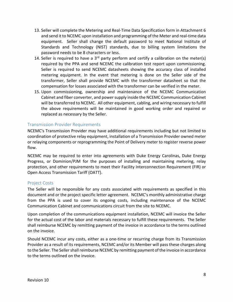
13. Seller will complete the Metering and Real-Time Data Specification form in Attachment 6 and send it to NCEMC upon installation and programming of the Meter and real-time data equipment. Seller shall change the default password to meet National Institute of Standards and Technology (NIST) standards, due to billing system limitations the password needs to be 8 characters or less.
14. Seller is required to have a 3rd party perform and certify a calibration on the meter(s) required by the PPA and send NCEMC the calibration test report upon commissioning. Seller is required to send NCEMC datasheets showing the accuracy class of installed metering equipment. In the event that metering is done on the Seller side of the transformer, Seller shall provide NCEMC with the transformer datasheet so that the compensation for losses associated with the transformer can be verified in the meter.
15. Upon commissioning, ownership and maintenance of the NCEMC Communication Cabinet and fiber converter, and power supply inside the NCEMC Communication Cabinet will be transferred to NCEMC. All other equipment, cabling, and wiring necessary to fulfill the above requirements will be maintained in good working order and repaired or replaced as necessary by the Seller.
Transmission Provider Requirements NCEMC's Transmission Provider may have additional requirements including but not limited to coordination of protective relay equipment, installation of a Transmission Provider owned meter or relaying components or reprogramming the Point of Delivery meter to register reverse power flow.
NCEMC may be required to enter into agreements with Duke Energy Carolinas, Duke Energy Progress, or Dominion/PJM for the purposes of installing and maintaining metering, relay protection, and other requirements to meet their Facility Interconnection Requirement (FIR) or Open Access Transmission Tariff (OATT).
Project Costs The Seller will be responsible for any costs associated with requirements as specified in this document and or the project specific letter agreement. NCEMC’s monthly administrative charge from the PPA is used to cover its ongoing costs, including maintenance of the NCEMC Communication Cabinet and communications circuit from the site to NCEMC.
Upon completion of the communications equipment installation, NCEMC will invoice the Seller for the actual cost of the labor and materials necessary to fulfill these requirements. The Seller shall reimburse NCEMC by remitting payment of the invoice in accordance to the terms outlined on the invoice.
Should NCEMC incur any costs, either as a one-time or recurring charge from its Transmission Provider as a result of its requirements, NCEMC and/or its Member will pass these charges along to the Seller. The Seller shall reimburse NCEMC by remitting payment of the invoice in accordance to the terms outlined on the invoice.

9 Revision 10
Information Timeline Interconnection Agreement Execution Upon execution of the Interconnection Agreement with the NCEMC Member, the Seller will furnish the following information to NCEMC:
1. Preliminary Meter information from Attachment 6 (make/model of Meter and what communication ports the meter will contain).
2. Site drawings showing location of NCEMC Communication Cabinet and Meter. 3. Site construction details such as Nameplate AC/DC capacity, Load/Capacity factor, Fixed
Racking (azimuth and altitude angle), Inverter (manufacturer, model), Tracker Racking (type, make, model), Modules (# of panels, manufacturer, model, and interconnection voltage.
4. Premise info such as site GPS coordinates and 911 address. 5. Name and contact information (address, email, and phone) of a person in charge who will
be NCEMC’s point of contact to establish site visit or communications regarding the project.
6. Name and contact information (address, email, and phone) of the person who will be responsible for processing NCEMC’s invoices.
7. Name and contact information (address, email, and phone) of a primary and back-up person who will be responsible for resolving operational and/or maintenance issues with equipment and wiring during the term of the PPA.
Upon reviewing the initial information, a site visit may be required to discuss the details of the project. This site visit may be held concurrently with the pre-construction meeting held with the NCEMC Member.
Once NCEMC has sufficient information to determine how the metering data, real-time telemetry data and curtailment signal will be transmitted to and from the associated site equipment, NCEMC will present the Seller’s person in charge with a Metering, Telemetry, and Curtailment Requirements letter for review and execution. A draft Metering, Telemetry, and Curtailment Requirements letter is provided in Attachment 5.
Project Construction Seller will keep NCEMC staff informed of the project progress and coordinate with NCEMC personnel during the installation of the Meter and real-time data equipment to ensure the timely installation of the communication equipment.
Project Commissioning Receiving Permission To Operate (PTO) is the final step under the Interconnection Agreement with the NCEMC Member and is not the same as fulfillment of your obligations set forth in this document.

10 Revision 10
General Requirements 1. Seller installs the metering, telemetry, and curtailment equipment as required in this
document. 2. NCEMC installs its communications equipment needed to satisfy requirements of this
document. 3. NCEMC confirms that Seller has installed the metering and telemetry equipment per
the Metering, Telemetry, and Curtailment Requirements letter and notifies the Seller of any deficiencies, if any are noted the Seller will complete any needed corrections.
4. NCEMC configures the telemetry and DERMS systems. Testing of the curtailment functionality will be verified.
Additional Requirements where NCEMC has the PPA In addition to the General Requirements above, additional the following steps outline the process for the purposes of declaring a Commercial Operation Date (COD) to begin payment under the PPA:
5. Seller correctly programs the meter and provides NCEMC the settings needed to communicate with the Meter. These settings will be documented in the Metering and Real-Time Data Specifications sheet – Attachment 6.
6. If the site metering equipment is installed on the low side of the step-up transformer, NCEMC will verify the meter has been properly programmed to reflect the power losses associated with the transformer.
7. NCEMC configures its billing system and verifies the meter programming based on the Metering and Real-Time Data Specifications sheet.
8. Once these steps have been completed, a COD date will be recommended for payment.
9. Seller and NCEMC or NCEMC Member execute a COD Notice for the PPA.
11 Revision 10
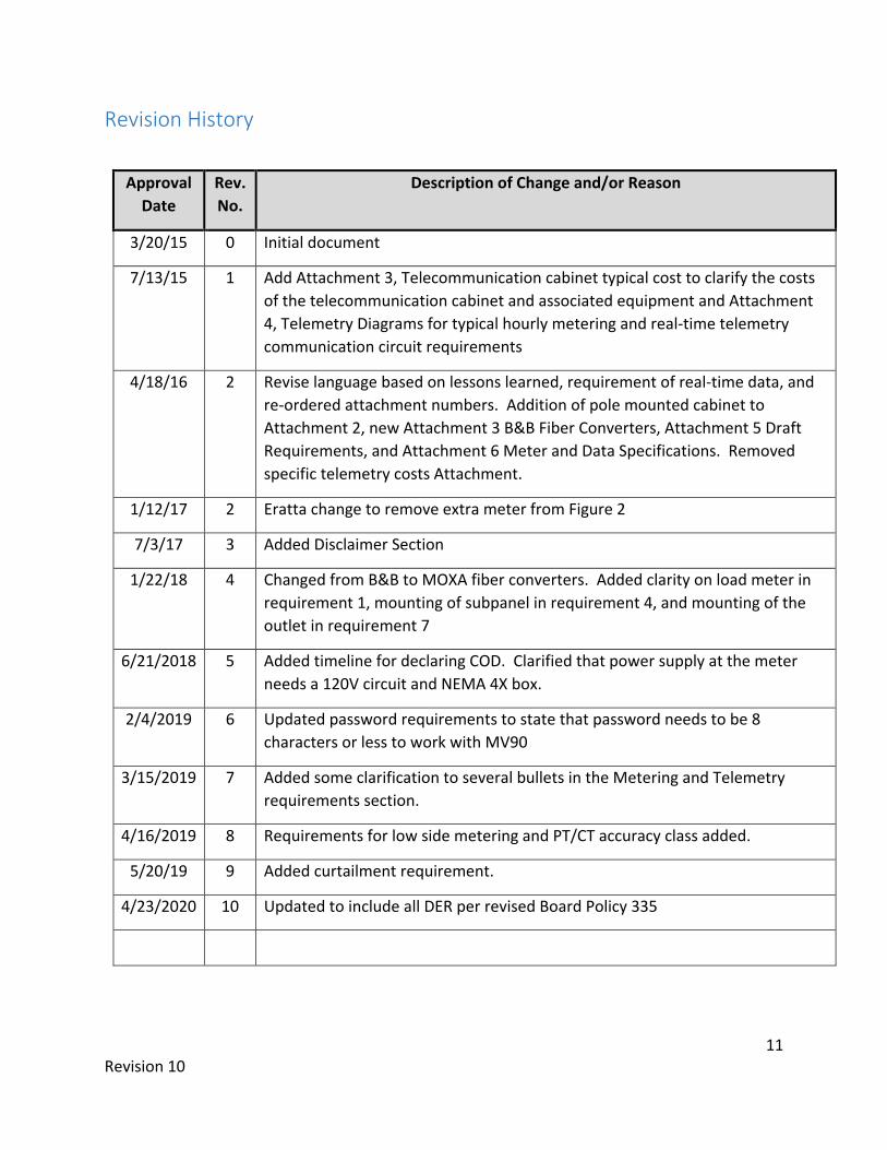
Revision History
Approval Date
Rev. No.
Description of Change and/or Reason
3/20/15 0 Initial document
7/13/15 1 Add Attachment 3, Telecommunication cabinet typical cost to clarify the costs of the telecommunication cabinet and associated equipment and Attachment 4, Telemetry Diagrams for typical hourly metering and real-time telemetry communication circuit requirements
4/18/16 2 Revise language based on lessons learned, requirement of real-time data, and re-ordered attachment numbers. Addition of pole mounted cabinet to Attachment 2, new Attachment 3 B&B Fiber Converters, Attachment 5 Draft Requirements, and Attachment 6 Meter and Data Specifications. Removed specific telemetry costs Attachment.
1/12/17 2 Eratta change to remove extra meter from Figure 2
7/3/17 3 Added Disclaimer Section
1/22/18 4 Changed from B&B to MOXA fiber converters. Added clarity on load meter in requirement 1, mounting of subpanel in requirement 4, and mounting of the outlet in requirement 7
6/21/2018 5 Added timeline for declaring COD. Clarified that power supply at the meter needs a 120V circuit and NEMA 4X box.
2/4/2019 6 Updated password requirements to state that password needs to be 8 characters or less to work with MV90
3/15/2019 7 Added some clarification to several bullets in the Metering and Telemetry requirements section.
4/16/2019 8 Requirements for low side metering and PT/CT accuracy class added.
5/20/19 9 Added curtailment requirement.
4/23/2020 10 Updated to include all DER per revised Board Policy 335

12 Revision 10
Attachment 1 – Communications Diagram
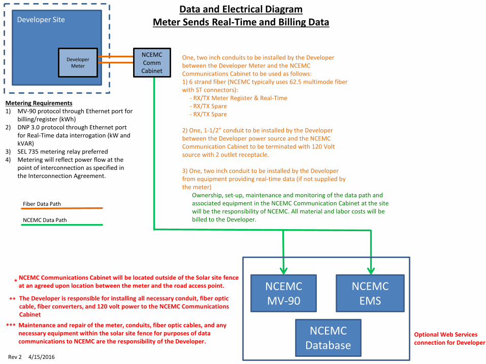
Metering Requirements1) MV-90 protocol through Ethernet port for
billing/register (kWh)2) DNP 3.0 protocol through Ethernet port
for Real-Time data interrogation (kW and kVAR)
3) SEL 735 metering relay preferred4) Metering will reflect power flow at the
point of interconnection as specified in the Interconnection Agreement.
Fiber Data Path
NCEMC Data Path
One, two inch conduits to be installed by the Developer between the Developer Meter and the NCEMC Communications Cabinet to be used as follows:1) 6 strand fiber (NCEMC typically uses 62.5 multimode fiber with ST connectors):
- RX/TX Meter Register & Real-Time- RX/TX Spare- RX/TX Spare
2) One, 1-1/2” conduit to be installed by the Developerbetween the Developer power source and the NCEMCCommunication Cabinet to be terminated with 120 Volt source with 2 outlet receptacle.
3) One, two inch conduit to be installed by the Developer from equipment providing real-time data (if not supplied by the meter)
Maintenance and repair of the meter, conduits, fiber optic cables, and any necessary equipment within the solar site fence for purposes of data communications to NCEMC are the responsibility of the Developer.
Data and Electrical DiagramMeter Sends Real-Time and Billing DataDeveloper Site
Ownership, set-up, maintenance and monitoring of the data path and associated equipment in the NCEMC Communication Cabinet at the site will be the responsibility of NCEMC. All material and labor costs will be billed to the Developer.
NCEMC Communications Cabinet will be located outside of the Solar site fence at an agreed upon location between the meter and the road access point. NCEMC
EMS
Rev 2 4/15/2016
The Developer is responsible for installing all necessary conduit, fiber optic cable, fiber converters, and 120 volt power to the NCEMC Communications Cabinet
*
**
***
NCEMC MV-90
Developer Meter
NCEMCComm
Cabinet
NCEMCDatabase
Optional Web Services connection for Developer

Metering Requirements1) MV-90 protocol through Ethernet port for
billing/register (kWh)2) DNP 3.0 protocol through Ethernet port
for Real-Time data interrogation (kW and kVAR)
3) SEL 735 metering relay preferred4) Metering will reflect power flow at the
point of interconnection as specified in the Interconnection Agreement.
Fiber Data Path
NCEMC Data Path
One, two inch conduits to be installed by the Developer between the Developer Meter and the NCEMC Communications Cabinet to be used as follows:1) 6 strand fiber (NCEMC typically uses 62.5 multimode fiber with ST connectors):
- RX/TX Meter Register- RX/TX Meter Real-Time- RX/TX Spare
2) One, 1-1/2” conduit to be installed by the Developerbetween the Developer power source and the NCEMCCommunication Cabinet to be terminated with 120 Volt source with 2 outlet receptacle.
3) One, two inch conduit to be installed by the Developer from equipment providing real-time data (if not supplied by the meter)
Maintenance and repair of the meter, conduits, fiber optic cables, and any necessary equipment within the solar site fence for purposes of data communications to NCEMC are the responsibility of the Developer.
Data and Electrical DiagramReal-Time and Billing Data Sent From Multiple DevicesDeveloper Site
Ownership, set-up, maintenance and monitoring of the data path and associated equipment in the NCEMC Communication Cabinet at the site will be the responsibility of NCEMC. All material and labor costs will be billed to the Developer.
NCEMC Communications Cabinet will be located outside of the Solar site fence at an agreed upon location between the meter and the road access point. NCEMC
EMS
Rev 2 4/15/2016
The Developer is responsible for installing all necessary conduit, fiber optic cable, fiber converters, and 120 volt power to the NCEMC Communications Cabinet
*
**
***
NCEMC MV-90
Developer Meter NCEMC
CommCabinet
NCEMCDatabase
Optional Web Services connection for Developer
DeveloperMeter/RTAC
13 Revision 10
Attachment 2 – NCEMC Communication Cabinet Specifications


14 Revision 10
Attachment 3 –Fiber Converter Specifications
FOSTC-0812-1/6 © 2002 by B&B Electronics. All rights reserved.
www.bb-elec.com [email protected] [email protected] International Office: 707 Dayton Road PO Box 1040 Ottawa, IL 61350 USA 815-433-5100 Fax 433-5104
European Office: Westlink Commercial Park Oranmore Co. Galway Ireland +353 91 792444 Fax +353 91 792445
PR
OD
UC
T IN
FO
RM
AT
IO
N
B&
B E
LE
CT
RO
NIC
S
TX
RX
FOSTC
RX
TX
FOSTC
RS-232RS-422
or RS-485Device
DuplexMultimode
Fiberor System
RS-232RS-422
or RS-485Device
or SystemSW1:6 = OFF SW1:6 = OFF
Point to Point
TX
RX
FOSTC
RX
TX
FO
ST
C
RS-232RS-422
or RS-485Device
MultimodeFiber
or System
RS-232RS-422
or RS-485Device
or System
RX
TX
FO
ST
C
RS-232RS-422
or RS-485Device
or System
RX
TX
FO
ST
C
RS-232RS-422
or RS-485Device
or System
SW1:6 = ON
SW
1:6
= O
N
SW
1:6
= O
N
SW
1:6
= O
N
Multi-Drop Ring
Model FOSTC
RS-232, 422 or 485 Signals Up To
2.5 Miles with Fiber Optic Modem
Description
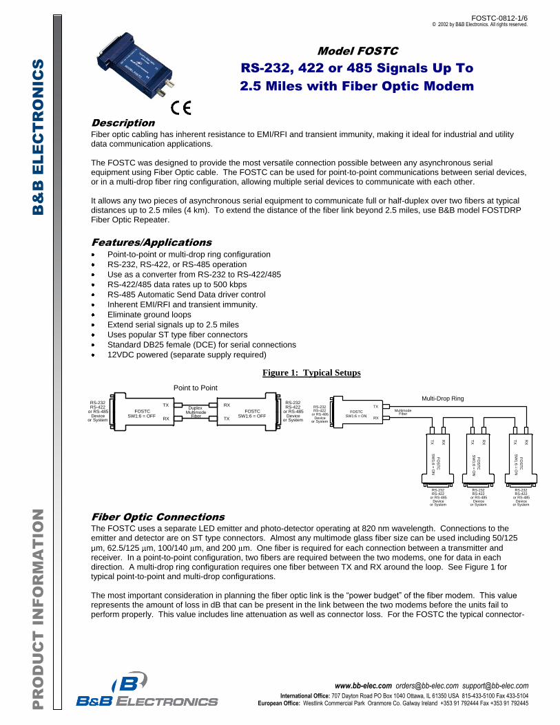
Fiber optic cabling has inherent resistance to EMI/RFI and transient immunity, making it ideal for industrial and utility data communication applications. The FOSTC was designed to provide the most versatile connection possible between any asynchronous serial equipment using Fiber Optic cable. The FOSTC can be used for point-to-point communications between serial devices, or in a multi-drop fiber ring configuration, allowing multiple serial devices to communicate with each other. It allows any two pieces of asynchronous serial equipment to communicate full or half-duplex over two fibers at typical distances up to 2.5 miles (4 km). To extend the distance of the fiber link beyond 2.5 miles, use B&B model FOSTDRP Fiber Optic Repeater.
Features/Applications
Point-to-point or multi-drop ring configuration
RS-232, RS-422, or RS-485 operation
Use as a converter from RS-232 to RS-422/485
RS-422/485 data rates up to 500 kbps
RS-485 Automatic Send Data driver control
Inherent EMI/RFI and transient immunity.
Eliminate ground loops
Extend serial signals up to 2.5 miles
Uses popular ST type fiber connectors
Standard DB25 female (DCE) for serial connections
12VDC powered (separate supply required)
Figure 1: Typical Setups
Fiber Optic Connections
The FOSTC uses a separate LED emitter and photo-detector operating at 820 nm wavelength. Connections to the emitter and detector are on ST type connectors. Almost any multimode glass fiber size can be used including 50/125
m, 62.5/125 m, 100/140 m, and 200 m. One fiber is required for each connection between a transmitter and receiver. In a point-to-point configuration, two fibers are required between the two modems, one for data in each direction. A multi-drop ring configuration requires one fiber between TX and RX around the loop. See Figure 1 for typical point-to-point and multi-drop configurations. The most important consideration in planning the fiber optic link is the “power budget” of the fiber modem. This value represents the amount of loss in dB that can be present in the link between the two modems before the units fail to perform properly. This value includes line attenuation as well as connector loss. For the FOSTC the typical connector-
FOSTC-0812-2/6 © 2002 by B&B Electronics. All rights reserved.
www.bb-elec.com [email protected] [email protected] International Office: 707 Dayton Road PO Box 1040 Ottawa, IL 61350 USA 815-433-5100 Fax 433-5104
European Office: Westlink Commercial Park Oranmore Co. Galway Ireland +353 91 792444 Fax +353 91 792445
PR
OD
UC
T IN
FO
RM
AT
IO
N
B&
B E
LE
CT
RO
NIC
S
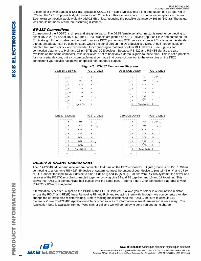
to-connector power budget is 12.1 dB. Because 62.5/125 m cable typically has a line attenuation of 3 dB per Km at 820 nm, the 12.1 dB power budget translates into 2.5 miles. This assumes no extra connectors or splices in the link. Each extra connection would typically add 0.5 dB of loss, reducing the possible distance by 166 m (547 ft.). The actual loss should be measured before assuming distances.
RS-232 Connections
Connection of the FOSTC is simple and straightforward. The DB25 female serial connector is used for connecting to either RS-232, RS-422 or RS-485. The RS-232 signals are pinned as a DCE device (input on Pin 2 and output on Pin 3). A straight through cable can be used from your DB25 port on any DTE device such as a PC or terminal. A standard 9 to 25-pin adapter can be used in cases where the serial port on the DTE device is a DB9. A null modem cable or adapter that swaps pins 2 and 3 is needed for connecting to modems or other DCE devices. See Figure 2 for connection diagrams to 9 pin and 25 pin DTE and DCE devices. Because RS-422 and RS-485 signals are also available on the same connector, take special care not to hook any external signals to these pins. This is not a problem for most serial devices, but a custom cable must be made that does not connect to the extra pins on the DB25 connector if your device has power or special non-standard outputs.
RS-422 & RS-485 Connections
The RS-422/485 driver and receiver are connected to 4 pins on the DB25 connector. Signal ground is on Pin 7. When connecting to a four-wire RS-422/485 device or system, connect the output of your device to pins 16 (B or +) and 17 (A or +). Connect the input to your device to pins 14 (B or +) and 15 (A or -). For two-wire RS-485 systems, the driver and receiver of the FOSTC must be connected together by tying pins 14 and 16 together and 15 and 17 together. This allows the FOSTC to communicate half-duplex over the same pair. Refer to Figure 3 for connection diagrams to your RS-422 or RS-485 equipment. If termination is needed, a spot on the PCBD of the FOSTC labeled Rt allows you to solder in a termination resistor across the RD(A) and RD(B) lines. Removing R8 and R16 and replacing them with through-hole components can also change the off-state bias resistor values. Before making modifications to the FOSTC, be sure to consult B&B Electronics’ free RS-422/485 Application Note or other sources of information to see if termination is necessary. The Application Note is available from our Web site, or call and we will be happy to send you one at no charge.
Figure 2: RS-232 Connection Diagrams
DB9 DTE Device
TD
RD
RTS
CTS
DTR
DSR
DCD
Signal GND
3
2
7
8
4
6
1
5
DB9 DCE Device
TD
RD
RTS
CTS
DTR
DSR
DCD
Signal GND
3
2
7
8
4
6
1
5
DB25 DTE Device FOSTC DB25
TD
RD
RTS
CTS
DTR
DSR
DCD
Signal GND
2
3
4
5
20
6
8
7
2
3
4
5
20
6
8
7
or
DB25 DCE Device
TD
RD
RTS
CTS
DTR
DSR
DCD
Signal GND
3 (RD)
2 (TD)
4
5
20
6
8
7
or
FOSTC DB25
FOSTC DB25 FOSTC DB25
2
3
4
5
6
8
7
2
3
4
5
20
6
8
7
3 (RD)
2 (TD)
4
5
20
6
8
7
FOSTC-0812-3/6 © 2002 by B&B Electronics. All rights reserved.
www.bb-elec.com [email protected] [email protected] International Office: 707 Dayton Road PO Box 1040 Ottawa, IL 61350 USA 815-433-5100 Fax 433-5104
European Office: Westlink Commercial Park Oranmore Co. Galway Ireland +353 91 792444 Fax +353 91 792445
PR
OD
UC
T IN
FO
RM
AT
IO
N
B&
B E
LE
CT
RO
NIC
S
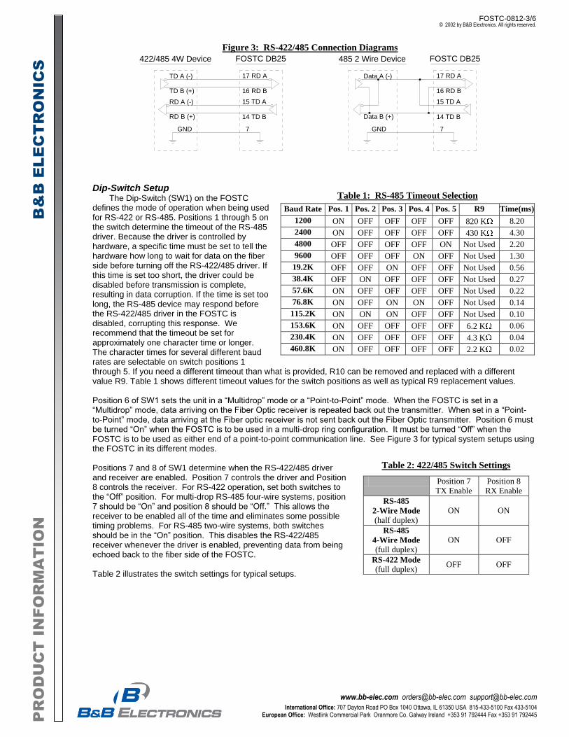
Table 1: RS-485 Timeout Selection
Baud Rate Pos. 1 Pos. 2 Pos. 3 Pos. 4 Pos. 5 R9 Time(ms)
1200 ON OFF OFF OFF OFF 820 K 8.20
2400 ON OFF OFF OFF OFF 430 K 4.30
4800 OFF OFF OFF OFF ON Not Used 2.20
9600 OFF OFF OFF ON OFF Not Used 1.30
19.2K OFF OFF ON OFF OFF Not Used 0.56
38.4K OFF ON OFF OFF OFF Not Used 0.27
57.6K ON OFF OFF OFF OFF Not Used 0.22
76.8K ON OFF ON ON OFF Not Used 0.14
115.2K ON ON ON OFF OFF Not Used 0.10
153.6K ON OFF OFF OFF OFF 6.2 K 0.06
230.4K ON OFF OFF OFF OFF 4.3 K 0.04
460.8K ON OFF OFF OFF OFF 2.2 K 0.02
Table 2: 422/485 Switch Settings
Position 7
TX Enable
Position 8
RX Enable
RS-485
2-Wire Mode
(half duplex)
ON ON
RS-485
4-Wire Mode
(full duplex)
ON OFF
RS-422 Mode
(full duplex) OFF OFF
Dip-Switch Setup The Dip-Switch (SW1) on the FOSTC defines the mode of operation when being used for RS-422 or RS-485. Positions 1 through 5 on the switch determine the timeout of the RS-485 driver. Because the driver is controlled by hardware, a specific time must be set to tell the hardware how long to wait for data on the fiber side before turning off the RS-422/485 driver. If this time is set too short, the driver could be disabled before transmission is complete, resulting in data corruption. If the time is set too long, the RS-485 device may respond before the RS-422/485 driver in the FOSTC is disabled, corrupting this response. We recommend that the timeout be set for approximately one character time or longer. The character times for several different baud rates are selectable on switch positions 1 through 5. If you need a different timeout than what is provided, R10 can be removed and replaced with a different value R9. Table 1 shows different timeout values for the switch positions as well as typical R9 replacement values. Position 6 of SW1 sets the unit in a “Multidrop” mode or a “Point-to-Point” mode. When the FOSTC is set in a “Multidrop” mode, data arriving on the Fiber Optic receiver is repeated back out the transmitter. When set in a “Point-to-Point” mode, data arriving at the Fiber optic receiver is not sent back out the Fiber Optic transmitter. Position 6 must be turned “On” when the FOSTC is to be used in a multi-drop ring configuration. It must be turned “Off” when the FOSTC is to be used as either end of a point-to-point communication line. See Figure 3 for typical system setups using the FOSTC in its different modes. Positions 7 and 8 of SW1 determine when the RS-422/485 driver and receiver are enabled. Position 7 controls the driver and Position 8 controls the receiver. For RS-422 operation, set both switches to the “Off” position. For multi-drop RS-485 four-wire systems, position 7 should be “On” and position 8 should be “Off.” This allows the receiver to be enabled all of the time and eliminates some possible timing problems. For RS-485 two-wire systems, both switches should be in the “On” position. This disables the RS-422/485 receiver whenever the driver is enabled, preventing data from being echoed back to the fiber side of the FOSTC. Table 2 illustrates the switch settings for typical setups.
Figure 3: RS-422/485 Connection Diagrams
422/485 4W Device
TD A (-)
TD B (+) 16 RD B
17 RD A
14 TD B
15 TD ARD A (-)
RD B (+)
7GND
FOSTC DB25 485 2 Wire Device
Data A (-)
16 RD B
17 RD A
14 TD B
15 TD A
Data B (+)
7GND
FOSTC DB25
FOSTC-0812-4/6 © 2002 by B&B Electronics. All rights reserved.
www.bb-elec.com [email protected] [email protected] International Office: 707 Dayton Road PO Box 1040 Ottawa, IL 61350 USA 815-433-5100 Fax 433-5104
European Office: Westlink Commercial Park Oranmore Co. Galway Ireland +353 91 792444 Fax +353 91 792445
PR
OD
UC
T IN
FO
RM
AT
IO
N
B&
B E
LE
CT
RO
NIC
S
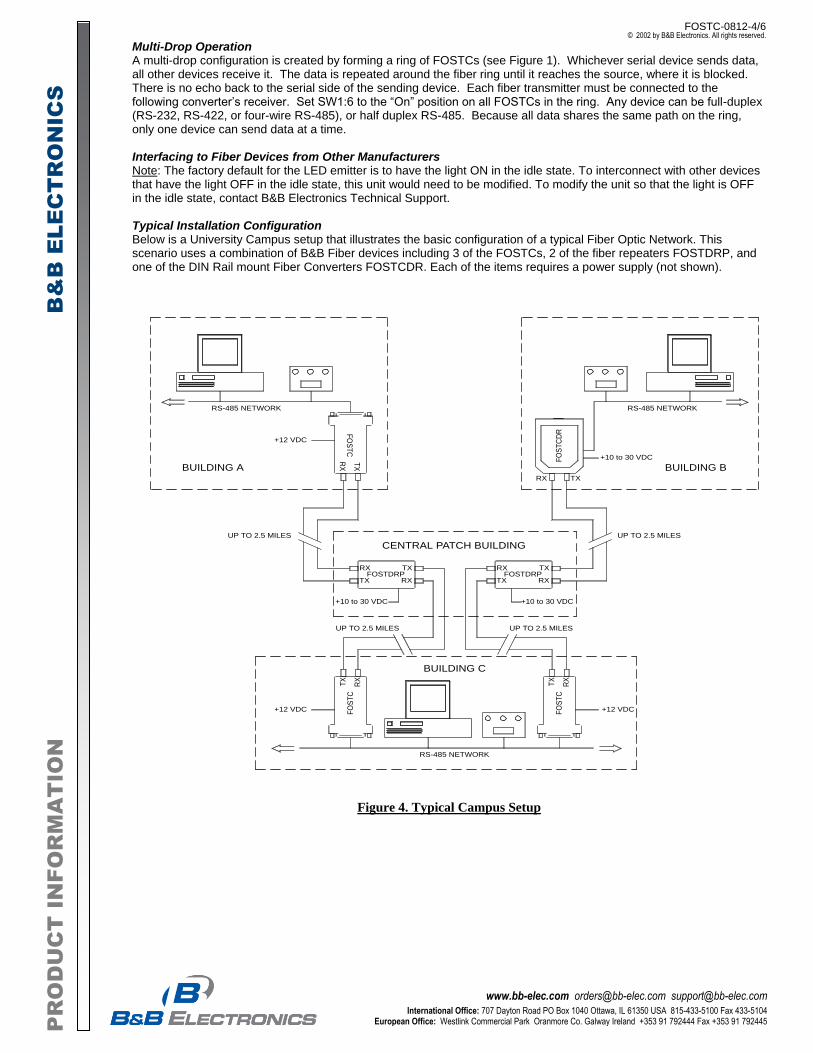
Multi-Drop Operation A multi-drop configuration is created by forming a ring of FOSTCs (see Figure 1). Whichever serial device sends data, all other devices receive it. The data is repeated around the fiber ring until it reaches the source, where it is blocked. There is no echo back to the serial side of the sending device. Each fiber transmitter must be connected to the following converter’s receiver. Set SW1:6 to the “On” position on all FOSTCs in the ring. Any device can be full-duplex (RS-232, RS-422, or four-wire RS-485), or half duplex RS-485. Because all data shares the same path on the ring, only one device can send data at a time. Interfacing to Fiber Devices from Other Manufacturers Note: The factory default for the LED emitter is to have the light ON in the idle state. To interconnect with other devices that have the light OFF in the idle state, this unit would need to be modified. To modify the unit so that the light is OFF in the idle state, contact B&B Electronics Technical Support. Typical Installation Configuration Below is a University Campus setup that illustrates the basic configuration of a typical Fiber Optic Network. This scenario uses a combination of B&B Fiber devices including 3 of the FOSTCs, 2 of the fiber repeaters FOSTDRP, and one of the DIN Rail mount Fiber Converters FOSTCDR. Each of the items requires a power supply (not shown).
RS-485 NETWORK
FO
ST
C
FOSTDRPRX
TX
TX
RX
TX
RX
RS-485 NETWORK
FO
ST
CD
R
RS-485 NETWORK
FO
ST
CT
X
RX
FO
ST
CT
X
RX
FOSTDRPRX
TX
TX
RX
BUILDING A BUILDING B
BUILDING C
UP TO 2.5 MILES UP TO 2.5 MILES
UP TO 2.5 MILES UP TO 2.5 MILES
CENTRAL PATCH BUILDING
+12 VDC
+10 to 30 VDC
+12 VDC +12 VDC
+10 to 30 VDC
RX TX
+10 to 30 VDC
Figure 4. Typical Campus Setup
FOSTC-0812-5/6 © 2002 by B&B Electronics. All rights reserved.
www.bb-elec.com [email protected] [email protected] International Office: 707 Dayton Road PO Box 1040 Ottawa, IL 61350 USA 815-433-5100 Fax 433-5104
European Office: Westlink Commercial Park Oranmore Co. Galway Ireland +353 91 792444 Fax +353 91 792445
PR
OD
UC
T IN
FO
RM
AT
IO
N
B&
B E
LE
CT
RO
NIC
S
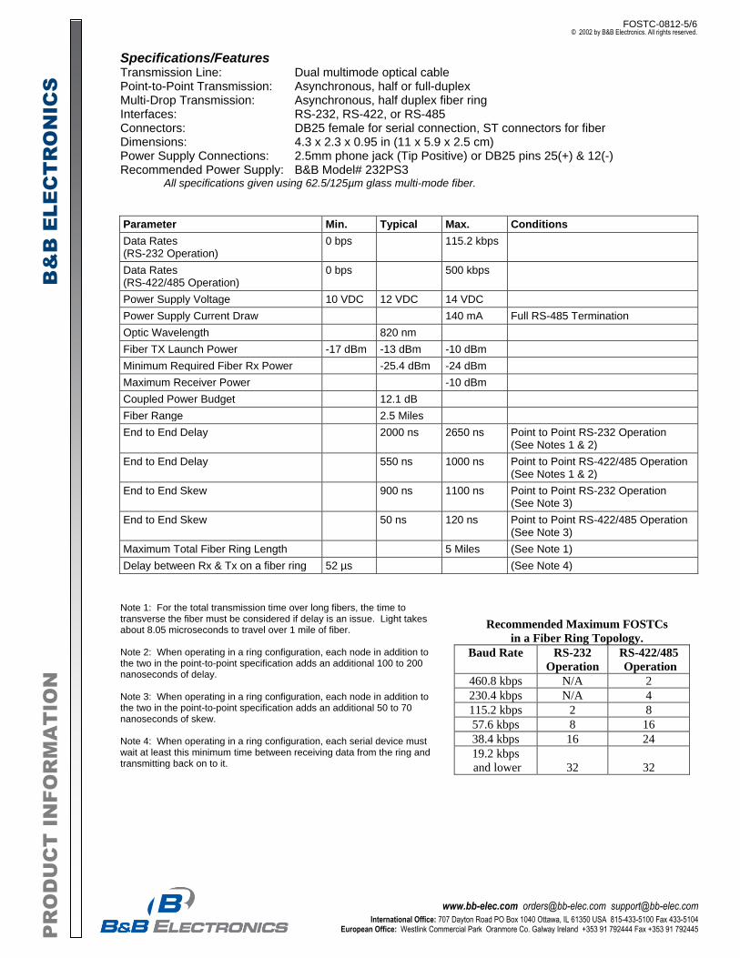
Recommended Maximum FOSTCs
in a Fiber Ring Topology.
Baud Rate RS-232
Operation
RS-422/485
Operation
460.8 kbps N/A 2
230.4 kbps N/A 4
115.2 kbps 2 8
57.6 kbps 8 16
38.4 kbps 16 24
19.2 kbps
and lower 32 32
Specifications/Features Transmission Line: Dual multimode optical cable Point-to-Point Transmission: Asynchronous, half or full-duplex Multi-Drop Transmission: Asynchronous, half duplex fiber ring Interfaces: RS-232, RS-422, or RS-485 Connectors: DB25 female for serial connection, ST connectors for fiber Dimensions: 4.3 x 2.3 x 0.95 in (11 x 5.9 x 2.5 cm) Power Supply Connections: 2.5mm phone jack (Tip Positive) or DB25 pins 25(+) & 12(-) Recommended Power Supply: B&B Model# 232PS3
All specifications given using 62.5/125µm glass multi-mode fiber.
Parameter Min. Typical Max. Conditions
Data Rates (RS-232 Operation)
0 bps 115.2 kbps
Data Rates (RS-422/485 Operation)
0 bps 500 kbps
Power Supply Voltage 10 VDC 12 VDC 14 VDC
Power Supply Current Draw 140 mA Full RS-485 Termination
Optic Wavelength 820 nm
Fiber TX Launch Power -17 dBm -13 dBm -10 dBm
Minimum Required Fiber Rx Power -25.4 dBm -24 dBm
Maximum Receiver Power -10 dBm
Coupled Power Budget 12.1 dB
Fiber Range 2.5 Miles
End to End Delay 2000 ns 2650 ns Point to Point RS-232 Operation (See Notes 1 & 2)
End to End Delay 550 ns 1000 ns Point to Point RS-422/485 Operation (See Notes 1 & 2)
End to End Skew 900 ns 1100 ns Point to Point RS-232 Operation (See Note 3)
End to End Skew 50 ns 120 ns Point to Point RS-422/485 Operation (See Note 3)
Maximum Total Fiber Ring Length 5 Miles (See Note 1)
Delay between Rx & Tx on a fiber ring 52 µs (See Note 4)
Note 1: For the total transmission time over long fibers, the time to transverse the fiber must be considered if delay is an issue. Light takes about 8.05 microseconds to travel over 1 mile of fiber. Note 2: When operating in a ring configuration, each node in addition to the two in the point-to-point specification adds an additional 100 to 200 nanoseconds of delay. Note 3: When operating in a ring configuration, each node in addition to the two in the point-to-point specification adds an additional 50 to 70 nanoseconds of skew. Note 4: When operating in a ring configuration, each serial device must wait at least this minimum time between receiving data from the ring and transmitting back on to it.
FOSTC-0812-6/6 © 2002 by B&B Electronics. All rights reserved.
www.bb-elec.com [email protected] [email protected] International Office: 707 Dayton Road PO Box 1040 Ottawa, IL 61350 USA 815-433-5100 Fax 433-5104
European Office: Westlink Commercial Park Oranmore Co. Galway Ireland +353 91 792444 Fax +353 91 792445
PR
OD
UC
T IN
FO
RM
AT
IO
N
B&
B E
LE
CT
RO
NIC
S
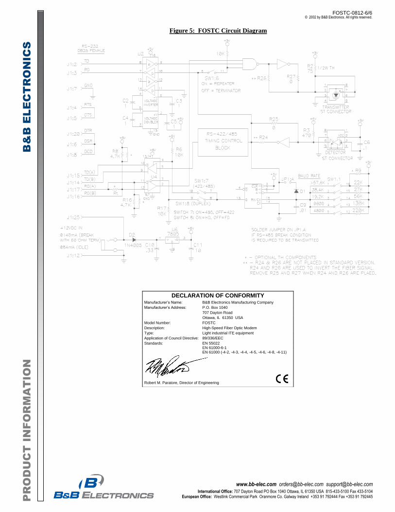
Figure 5: FOSTC Circuit Diagram
DECLARATION OF CONFORMITY Manufacturer’s Name: B&B Electronics Manufacturing Company
Manufacturer’s Address: P.O. Box 1040
707 Dayton Road
Ottawa, IL 61350 USA
Model Number: FOSTC
Description: High-Speed Fiber Optic Modem
Type: Light industrial ITE equipment
Application of Council Directive: 89/336/EEC
Standards: EN 55022 EN 61000-6-1 EN 61000 (-4-2, -4-3, -4-4, -4-5, -4-6, -4-8, -4-11)
Robert M. Paratore, Director of Engineering
1 w w w. m o x a . c o m i n f o @ m o x a . c o m
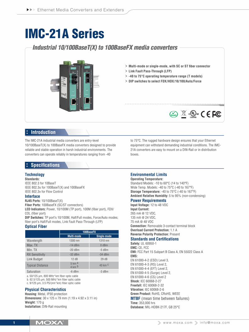
Ethernet Media Converters and Extenders
Industrial 10/100BaseT(X) to 100BaseFX media converters
The IMC-21A industrial media converters are entry-level 10/100BaseT(X) to 100BaseFX media converters designed to provide reliable and stable operation in harsh industrial environments. The converters can operate reliably in temperatures ranging from -40
Introduction
Specifications
to 75°C. The rugged hardware design ensures that your Ethernet equipment can withstand demanding industrial conditions. The IMC-21A converters are easy to mount on a DIN-Rail or in distribution boxes.
IMC-21A Series
› Multi-mode or single-mode, with SC or ST fiber connector
› Link Fault Pass-Through (LFP)
› -40 to 75°C operating temperature range (T models)
› DIP switches to select FDX/HDX/10/100/Auto/Force
TechnologyStandards: IEEE 802.3 for 10BaseT IEEE 802.3u for 100BaseT(X) and 100BaseFX IEEE 802.3x for Flow ControlInterfaceRJ45 Ports: 10/100BaseT(X)Fiber Ports: 100BaseFX (SC/ST connectors)LED Indicators: Power, 10/100M (TP port), 100M (fiber port), FDX/COL (fiber port)DIP Switches: TP port’s 10/100M, Half/Full modes, Force/Auto modes; fiber port’s Half/Full modes, Link Fault Pass-Through (LFP)Optical Fiber
100BaseFXMulti-mode Single-mode
Wavelength 1300 nm 1310 nm
Max. TX -14 dBm 0 dBm
Min. TX -20 dBm -5 dBm
RX Sensitivity -32 dBm -34 dBm
Link Budget 12 dB 29 dB
Typical Distance 5 km a4 km b 40 km c
Saturation -6 dBm -3 dBm
a. 50/125 μm, 800 MHz*km fiber optic cableb. 62.5/125 μm, 500 MHz*km fiber optic cablec. 9/125 μm, 3.5 PS/(nm*km) fiber optic cable
Physical CharacteristicsHousing: Metal, IP30 protectionDimensions: 30 x 125 x 79 mm (1.19 x 4.92 x 3.11 in)Weight: 170 gInstallation: DIN-Rail mounting
Environmental LimitsOperating Temperature: Standard Models: -10 to 60°C (14 to 140°F) Wide Temp. Models: -40 to 75°C (-40 to 167°F)Storage Temperature: -40 to 75°C (-40 to 167°F)Ambient Relative Humidity: 5 to 95% (non-condensing)Power RequirementsInput Voltage: 12 to 48 VDCInput Current: 265 mA @ 12 VDC, 135 mA @ 24 VDC, 75 mA @ 48 VDCConnection: Removable 3-contact terminal blockOverload Current Protection: 1.1 AReverse Polarity Protection: PresentStandards and CertificationsSafety: UL 60950-1EMC: CE, FCCEMI: FCC Part 15 Subpart B Class A, EN 55022 Class AEMS: EN 61000-4-2 (ESD) Level 3, EN 61000-4-3 (RS) Level 2, EN 61000-4-4 (EFT) Level 2, EN 61000-4-5 (Surge) Level 2, EN 61000-4-6 (CS) Level 2Shock: IEC 60068-2-27Freefall: IEC 60068-2-32Vibration: IEC 60068-2-6Green Product: RoHS, CRoHS, WEEEMTBF (mean time between failures)Time: 353,000 hrsDatabase: MIL-HDBK-217F, GB 25°C

2 w w w. m o x a . c o m i n f o @ m o x a . c o m
Ethernet Media Converters and Extenders
DimensionsUnit: mm (inch)
Rear ViewFront ViewSide View Bottom ViewTop View
Ordering Information
Available ModelsIMC-21A-M-SC: Industrial 10/100BaseT(X) to 100BaseFX media converter, multi mode, SC connector, -10 to 60°C operating temperatureIMC-21A-M-ST: Industrial 10/100BaseT(X) to 100BaseFX media converter, multi mode, ST connector, -10 to 60°C operating temperatureIMC-21A-S-SC: Industrial 10/100BaseT(X) to 100BaseFX media converter, single mode, SC connector, -10 to 60°C operating temperatureIMC-21A-M-SC-T: Industrial 10/100BaseT(X) to 100BaseFX media converter, multi mode, SC connector, -40 to 75°C operating temperatureIMC-21A-M-ST-T: Industrial 10/100BaseT(X) to 100BaseFX media converter, multi mode, ST connector, -40 to 75°C operating temperatureIMC-21A-S-SC-T: Industrial 10/100BaseT(X) to 100BaseFX media converter, single mode, SC connector, -40 to 75°C operating temperatureOptional Accessories (can be purchased separately)SC to ST Connectors: See Appendix A
Package Checklist• 1 IMC-21A media converter• Quick installation guide (printed)• Warranty card
WarrantyWarranty Period: 5 yearsDetails: See www.moxa.com/warranty
78.8 (3.10)18
(0.71)30
(1.19)
30 (1.19)
18(0.71)
M3
M3
33.2 (1.31)48.4 (1.91)
105 (4.13)
115 (4.53)10 (0.39)
70 (2.76)
V+
V-

3
Ethernet Media Converters and Extenders
© Moxa Inc. All Rights Reserved. Updated Mar. 28, 2014. Specifications subject to change without notice. Please visit our website for the most up-to-date product information.
ADP-SCm-STf-SSC male to ST female duplex adaptor for single-mode fiber
SpecificationsSingle-mode: 9/125 μmFerrules and Sleeves: Zirconia CeramicBody Color: BlueInsertion Loss: 0.5/1.1 (TYP/MAX)SC-side Connector: SC maleST-side Connector: ST female
ADP-SCm-STf-MSC male to ST female duplex adaptor for multi-mode fiber
SpecificationsMulti-mode: 62.5/125 μmFerrules and Sleeves: Zirconia CeramicBody Color: GrayInsertion Loss: 0.1/0.3 (TYP/MAX)SC-side Connector: SC maleST-side Connector: ST female
SC male to ST female duplex adaptors
These SC male to ST female duplex adaptors are provided as an optional accessory to give users of Moxa industrial Ethernet switches more fiber optic connection options. Simply plug the adaptors directly into the SC connector of any Moxa industrial Ethernet switch to convert the original SC connector into an ST connector. This allows you to use an ST connector with any MOXA industrial Ethernet switch, but without the need for an extra patchcord.
Fiber AccessoriesFiber Optic Adaptors

15 Revision 10
Attachment 4 – MV-90 Supported Meters
Vendor Devices TIM TypeProbe Support
Decode Support
American Innovations EMM 330 EMM ElectricAmetek EXJ register w/ JEM1 EXJ Electric YesAmetek JEM10 JM10 Electric YesAmetek JEM10 for Saudi Arabia J10D ElectricAmetek JEM2 with ASCII protocol JE2A Electric YesAmetek JEM2 with Binary protocol JE2B Electric YesAmetek JEMSTAR and Ci20 meter JMST Electric Yes YesAmetek JEMStar II JST2 Electric Yes YesAmetek JR1 JR1 ElectricAmetek JR1 w/ RTS -CTS Flow Control (NIPCO) JR1F ElectricAMPY (Email Metering) A-11L Meter A11L Electric YesAMPY (Email Metering) EM3300 Meter EM33 Electric Yes NoAMPY (Email Metering) Email Model A11 Meter EA11 Electric No NoAMPY (Email Metering) Email P1 Meter EMP1 Electric Yes YesAMPY (Email Metering) Email P1 Single Phase Meter EMAL Electric No NoAMPY (Email Metering) Q3, Q4 Meter EMQ4 Electric Yes YesAptech 403 load control firmware, E-ICT WebRTU ATC4 Electric YesAptech 804 recorder (PSI Sentry 100 clones) ATC1 Electric YesAptech 804 test mode firmware ATC3 Electric YesAptech 804 timed relay control ATC2 Electric YesAustin International Sentry 200 Sentry 300 EG PSI2 ElectricAustin International Vision 20 Meter VS20 Electric Yes YesBristol Babcock Total Flow BBTF GasCEWE Prometer 2243 CEWE Electric Yes YesCEWE Prometer R and W CPM2 Electric Yes YesDaniels Solarflow Plus 2470, 2480 SOLF Gas YesDataWatt Datawatt D15 D15 ElectricDataWatt Datawatt D17 DWAT Electric YesDataWatt MidiElcor ELCR GasDomestic Automation LINC LINC Electric YesDresser ROOTS Micro PTZ+ Log Meter MPTZ Gas No NoDresser ROOTS MicroCorrector PTZ2 GasEagle Research PAT2, PAT4, AE2000, AE5000, AE6000, XARTU, MPPlus AE Gas YesED&A HPC Datalogger HPC Electric NoEDMI MK10 (Atlas Meter) EDMX Electric Yes YesEDMI MK2 System 2000-01xx Energy Meter and MK3 System 2000-04xx Energy
Meter EDM Electric Yes YesEDMI MK6 System 2000 (Genius Energy Meter) EDM6 Electric Yes YesElectro Industries EIG Shark 270/250 electric meter SK27 Electric Yes YesElectro Industries Futura EIF ElectricElectro Industries Nexus 1250 and 1270 series meters NEXS/NXSP Electric YesElectro Industries Nexus 1252/1262, 1272, 1450 and 1500 Series Meters NEX2 Electric Yes YesElectro Industries Shark 200 SHK2 Electric No YesElgama Elektronika Lithuania EPQS EG21 Electric Yes YesElgama Elektronika Lithuania EPQS EG31 Electric Yes YesElspec Blackbox G4410, G4420 and G4430 ELG4 Electric No NoElster A3 Alpha, A1800 IEC meter, A3 WIC (probe) A3, A3P Electric Yes YesElster A3 WIC -- MV-90 xi Remote only A3IP Electric No YesElster Alpha meter (A1), EMF-2460 ALPH Electric Yes YesElster Alpha PowerPlus Meter (A2) ALPP Electric Yes YesElster EMF registers in 25xx & 26xx families EMF Electric Yes YesElster IEC Alpha Meter ALPI Electric YesElster REX Universal Meter - WIC Remote Only REXW Electric No YesElster REX Universal WIC Electric Meter REXP Electric Probe Only YesElster Germany A140, A120 A140 Electric YesElster Germany AEM500, A1350, A1500, A2500, and A(S)220 A500 Electric YesElster Germany AS1440 AS14 Electric No YesElster UK Alpha Vision meter (A1700) VISI Electric Yes YesElster UK AS230 A230 Electric Yes YesElster UK Elster A1120 and the A1140 Meters VI40 Electric Yes YesElster UK OPUS Family of Outstations OPUS Electric YesElster UK PPM Polyphase Programmable Meter GECP Electric YesElster UK PPM Polyphase Programmable Meter Issue2 GEC2 Electric YesElster/Itron A3 w/ 2G ICS Module A32G Electric No YesElster/Itron A3 with ICS module A3I Electric No Yes
MV-90 xi & MVLT xiDevices Supported List 05-Sep-2019
Page 1
Vendor Devices TIM TypeProbe Support
Decode Support
EMH - Elektrizitätszähler GmbH & Co KG LZQJ-XC meters dlms/ COSEM protocol LZQ Electric Yes YesEMH - Elektrizitätszähler GmbH & Co KG LZQJ-XC meters VDEW w 62056-021 protocol LZQ2 Electric Yes YesEMON (MeterSmart) 8 channel I-MON and 3 channel PRO-MON EMON ElectricEnergy Intellect Energy Intellect VM Series Meter VM Electric Yes YesEnergy Intellect TM, TMA TML Electric YesEnermet MT30E, MT40, E700, E200 and E600 ENMT Electric Yes YesEquimeter EC3000 Autocorrector/NexCorr ACOR Gas YesEquimeter Electrocorrector P & T EQM Gas YesFisher (Emerson Process Management) FloBoss107 F107 Gas No NoFisher (Emerson Process Management) ROC 300 series, FloBoss 407 and 500 series FROC Gas NoFlonidan UNIFLO 1200 FUNI Gas No YesGalvanic Applied Sciences EVC, EPR, ER, and IDR devices GAL Gas No NoGE DR87, DR87/1, DR87/2 DR87 Electric YesGE GE TMx and TMRx meters, L&G DCx meters (Tx8x, Tx9x) TMR Electric Probe Only YesGE I210 I210 Electric Yes YesGE kV (a.k.a. kV96) meter KV Electric Yes YesGE kV2, kV2c, kV2c+, kV2ce, kV2cs, SM300 KV2 Electric Yes YesGE Phase 3 (KRC-901, KTC-901, KM-901), EV and ES Meter platforms PH3 Electric Yes YesGE/Itron I210 w/ 2G ICS module I22G Electric No YesGE/Itron I210 with ICS module I21I Electric No YesGE/Itron KV2c with ICS module KV2I Electric No YesInstromet 999 and 555 Corrector I999 GasIntellimeter Meter Data Collection System WebService MDCS Electric No NoIskraemeco MT372/MT375 M372 Electric Yes YesIskraemeco MT420/ME420 M420 Electric YesIskraemeco MT85x, MT830, MT 860. MT831 M851 Electric YesIskraemeco MT880 & MT38x MT88 Electric Yes YesIskraemeco POREG2 ISK2 Electric YesIskraemeco POREG4 ISK4 Electric YesItron 200 Series (MT200 & MTR200) and Centron M200 Electric Yes YesItron CENTRON II CEN2 Electric Yes YesItron Centron Image CENT Electric Yes YesItron CEntron Image w/ 2G ICS module CNTI Electric No YesItron Datastar Recorder, L&G DG100's SANG Electric YesItron EM211 Meter EM21 Electric Probe Only YesItron Fulcrum FULC Electric Yes YesItron Indigo+ International INDI Electric YesItron Indigo+ Meter INDP Electric Yes YesItron MT100/STD101 M100 Electric Yes YesItron OpenWay CENTRON Cellular Meter - MV-90 xi remote only CENI Electric No YesItron OpenWay CENTRON, CENTRON Bridge, CENTRON II Cellular (probe) OWC Electric Yes YesItron PXA-5 /R PXAR Electric Yes YesItron Q1000 Q1K Electric Yes YesItron Quantum QNTM Electric Yes YesItron Quantum w/ QDIF Board QDIF Electric YesItron Sentinel STLP Electric Yes YesItron Sentinel w/ 2G ICS module STLI Electric No YesItron SEVC-D SEVC Gas YesItron SL7000, ACE6000, ACE7000 & ACE8000 SL7K Electric Yes YesItron Spectra A12E recorder SPEC Electric YesItron SQ400 SQ4 Electric YesItron TIM Itron/Actaris CORUS gas volume converter (MID) CORS Gas Yes YesItron Vectron VTRN Electric Yes YesKamstrup UNIGAS and UNILOG devices KUNI Gas No YesKenda Medo Outstation device MED ElectricKenda Meteor Outstation device MTR ElectricKIGG KM3T, KM3D TIM_KM3P Electric Yes YesLandis+Gyr Clone of PSI Sentry 100 LNG1 Electric YesLandis+Gyr Clone of PSI Sentry 100 with timed relay LNG2 Electric YesLandis+Gyr CTR101 & 102 registers CTR ElectricLandis+Gyr DXR DXR Electric Yes YesLandis+Gyr E650 S4X S4X Electric Probe Only YesLandis+Gyr EKM 647 and ZMB T647 EKM Electric Probe Only NoLandis+Gyr EM5400 meter EM54 Electric Yes YesLandis+Gyr Focus AX and RX ANSI meter FOCS Electric Yes YesLandis+Gyr RXR S3, AXR & RXR S4, ZMC, SSM-4, Altimus RXR Electric Yes YesLandis+Gyr S4E ANSI Meter S4E Electric Yes YesLandis+Gyr Sentry 100 PSI1 Electric YesLandis+Gyr Sentry 100 w/ load control firmware PSI4 Electric Yes
Page 2
Vendor Devices TIM TypeProbe Support
Decode Support
Landis+Gyr Sentry 200 PSI2 Electric YesLandis+Gyr Sentry 200 w/ test mode firmware PSI3 Electric YesLandis+Gyr Sentry 200/EXP & QUAD4 & alpha cust id EXPA ElectricLandis+Gyr Sentry 200/EXP recorder, Quad 4+, MAXsys 2410, 2510, and Elite EXP Electric Yes YesLandis+Gyr U1200, S1200 LGUA Electric Probe Only YesLandis+Gyr Zug 7ED62 (L+G Download Restrictions apply to SCTM devices) 7E62 Electric YesLandis+Gyr Zug EMT - 21xx & FCM3 (L+G Download Restrictions apply to SCTM devices) FCM Electric YesLandis+Gyr Zug FAF -11/12/21.2/22 (L+G Download Restrictions apply to SCTM devices) FAF Electric YesLandis+Gyr Zug FAG Meter (L+G Download Restrictions apply to SCTM devices) FAG Electric YesLandis+Gyr Zug FBC meter (L+G Download Restrictions apply to SCTM devices) FBC Electric YesLandis+Gyr Zug FCL /1 (L+G Download Restrictions apply to SCTM devices) FCL Electric YesLandis+Gyr Zug FCR meter (L+G Download Restrictions apply to SCTM devices) FCR Electric YesLandis+Gyr Zug METCOM3 Modem (L+G Download Restrictions apply to SCTM devices) MET3 ElectricLandis+Gyr Zug ZMB/EKM through L&G METCOM2 Modem (L+G Download Restrictions
apply to SCTM devices) MET2 ElectricLandis+Gyr Zug ZxD, SxA (E650/S650 Series 3), ZxQ, ZxG Meters DLMS/ COSEM device ZMD Electric Yes YesLG Idustrial Systems LGRW34 Meter LGIS, LGS2 Electric Yes NoMercury EC-AT, MINI-AT, MINI-MAX, MINI-MAX-AT, MPA and ER MERB Gas Yes YesMetretek Commercial Pulse Accumulator CPA GasMetretek SIP, IMU, and IMU2 SIP GasMetretek SMOD (for SMOD versions before '93) MTEK Gas YesMetscan/Itron CID 30 MCID GasMetscan/Itron CMD2000 MCMD GasMetscan/Itron RMD 4.0LP MRMD GasMiM (Malaysian Intelligence Meters) Smart Anti Tamper meter MIM Electric Yes YesMisa Miestro-3 (dlms) MIE3 Electric Yes YesMisa Miestro-CT MIES Electric Yes YesMitsubishi MX2 MX2 Electric Yes YesNilsen EMS2600e, 26FRC NL26 Electric YesPRI CALMU3 LINK LINK Electric YesPRI CALMU3, CALMU3+, Sprint, and Premier meters CMU3 Electric Yes YesPRI Premier meters supporting PACT,PAKNET,LBP,and PACT+ protocols CMUX Electric Yes YesQuadlogic Quadlogic Series 5 Transmeters, MiniClosets and Transponders QLS5 ElectricReynolds 323 LVC, XVC Volume Corrector RLVC GasReynolds In-line 841, 881r INLI Gas YesReynolds Recor 843 using Meter number for ID RECM Gas YesReynolds Recor 843 using serial number for ID RECR Gas YesReynolds Reynolds RVC /HVC Series Volume Correctors RRVC Gas No NoRobinton/ Aptech LPR LPR Electric YesSATEC BFM 136/036 B136 Electric No YesSATEC EM133 E133 Electric Yes YesSATEC EM920 EM92 Electric Yes YesSATEC PM172E SATC Electric No YesSATEC PM174/PM175/PM180 P174 Electric YesSchneider Electric (Power Measurements/Square-D)
ION 7300,7330,7350,7400,7500,7550,7600,7650,7700,8000 series, 9000 series, PM8000 series ION Electric Yes Yes
Schweitzer Engineering Labs (SEL) SEL-734 meter using the Modbus protocol S734 Electric YesSchweitzer Engineering Labs (SEL) SEL-734 meter using the SEL ASCII protocol 734A Electric NoSchweitzer Engineering Labs (SEL) SEL-735 meter using the SEL ASCII protocol 735A Electric YesScientific Columbus Scientific Columbus JEM-II (ASCII protocol) JE2W Electric No NoSensus Sensus iCON APEX IAPX Electric Yes YesSiemens UK CM32 Outstation CM32 Electric No NoSiemens UK S4S register S4S Electric YesSiemens/Dietrich MBUS MBUS ElectricSiris 50G Gas Recorder S50G Gas No NoSmartNet Mk2 PIM and PIM3 SMNT Electric Yes YesSquare D (Schneider Electric) CM2350 Circuit Monitor SQD ElectricStrike Technologies ENERMAX meter EMX ElectricStrike Technologies ENERMAX+ EMXP Electric Yes YesTeldata/ First Point AC4, DC4, TDS-4M, TDS-2 TLDT GasTelecontrols Optimodem OPM Electric YesTransdata EMS-65, EMS-80, EMS-96, EMS-99, MARK V, SSR6000 Recorder EMS Electric Yes YesTrilliant Networks/ Nertec Design TL402 Telereader TL4 Gas No NoWestinghouse EWR with Bubble Memory EWR1 ElectricWestinghouse SPRITE recorder SPRI Electric YesZaptronix Model ZAP03BE IMS ElectricZIV 5CT series 5CTX Electric Yes Yes
Page 3
16 Revision 10
Attachment 5 – Draft Metering, Telemetry, and Curtailment Requirements Letter

[Developer Person In Charge Last Name] 1 [Date]
[Date] [Developer Person In Charge Name] [Developer Person in Charge Title] [Developer] [Developer Person In Charge Mailing Address] RE: North Carolina Electric Membership Corporation (NCEMC) Metering, Telemetry,
and Curtailment Requirements for ______________________ Project Dear [Person In Charge Name]: This letter is intended to supplement the ______________ Power Purchase Agreement (PPA) executed between the buyer and [Developer Holding Company] to outline NCEMC’s requirements for metering, telemetry, and curtailment. References below to the Developer refer either to [Developer] or [Developer Holding Company] or both, depending upon how Developer] and [Developer Holding Company] have allocated responsibilities. Material Installation for Metering and Real-time Data [Restatement of requirements and any special project requirements] Billing NCEMC estimates the cost for materials and labor related to fulfill its requirements above will be $_,000. NCEMC will bill the Developer for the actual cost of the labor and materials necessary to fulfill the above requirements by sending the final bill:
[Developer Billing Contact] [Developer] [Developer Billing Contact Address] [Developer Billing Contact E-mail Address] [Developer Billing Contact Phone Number(s)]
Developer agrees to reimburse NCEMC by remitting payment of the invoice in accordance to the terms outlined on the invoice.

[Developer Person In Charge Last Name] 2 [Date]
Installation NCEMC’s contact for the installation of the communications equipment:
[NCEMC Installer] North Carolina Electric Membership Corporation 3400 Sumner Boulevard Raleigh, NC 27616 [NCEMC Installer E-mail Address] [NCEMC Installer Phone Number(s)]
To ensure accurate configuration of the meter and real-time data into our SCADA the Developer will need to provide NCEMC with the information in the Metering and Real-Time Data Specifications document. Operational Issues Upon commissioning of the project during the PPA term, should NCEMC need to contact the Developer regarding but not limited to operational issues with equipment and wiring used to communicate to the Meter, the following is the Developer’s contact:
[Developer Operational Contact] [Developer] [Developer Operational Contact Address] [Developer Operational Contact E-mail Address] [Developer Operational Contact Phone Number(s)] [Developer Operational Backup Contact] [Developer] [Developer Operational Backup Contact Address] [Developer Operational Backup Contact E-mail Address] [Developer Operational Backup Contact Phone Number(s)]
Developer agrees to make a good faith effort to resolve operational issues within three (3) business days. Should the Developer determine that additional time is needed, Developer shall contact NCEMC’s billing department contact below to describe the nature of the problem and provide an estimate of when the issue will be resolved:
[NCEMC Billing Analyst] North Carolina Electric Membership Corporation 3400 Sumner Boulevard Raleigh, NC 27616 [NCEMC Billing Analyst E-mail Address] [NCEMC Billing Analyst Phone Number(s)]

[Developer Person In Charge Last Name] 4 [Date]
Timeline Receiving permission to operate (PTO) is the final step under the Interconnection Agreement with the Cooperative but is not the same as fulfillment of obligations under the PPA. The process for the purposes beginning payment under the PPA is as follows: [Restatement of requirements and any special project requirements for COD] If you have any questions, please feel free to contact me at (XXX) XXX-XXXX. If these requirements are acceptable please acknowledge by signing and returning a copy of this letter to my attention. Sincerely, [NCEMC Staff] [NCEMC Staff Title] Attachments: Communications Diagram.pdf Communications Cabinet.pdf Fiber Converter Specifications.pdf Metering and Real-Time Data Specifications.pdf cc: Agreed to by:
Name: _______________________________________
Signature: _______________________________________
Title: _______________________________________
Company: _______________________________________
Date: _______________________________________ Project: ______________________________ Project

17 Revision 10
Attachment 6 – Metering and Real-Time Data Specifications

1
_____________ Project Metering and Real-Time Data Specifications
NCEMC uses a master DNP address of 1 which cannot be changed. To ensure accurate configuration of the meter and real-time data into our SCADA the following information in Sections 1-3 are needed from the Developer. The meter shall be installed as a load meter for purposes of CT and PT wiring (positive flow is when the project is generating and negative flow is station service when not generating).
Section 1 - Billing Meter Manufacturer and Model
Meter Identification (MID) Using the acSELerator Quicket software navigate to > General > Identifier and Scaling > MID
Meter Serial Number
Meter Wiring Method (Form 5,9 or 36) Verify that the meter is wired as a Load Meter
CT Ratio Using the acSELerator Quicket software navigate to > General > Identifier and Scaling > CTR
PT Ratio Using the acSELerator Quicket software navigate to > General > Identifier and Scaling > PTR
Is CT and PT Ratio set in the Meter Yes ☐ No ☐
Full Scale Value
Watt Volt Amp
Meter Multiplier
Pulse Multiplier
Meter Constant
Meter Password (Level 1 and Level 2) Level 1: Level 2:
NCEMC requires the meter password to be changed from the default. We suggest following previous NIST standards for password complexity. • Maximum of 8 characters (limited by firmware/software) • Upper and lower case letters and numbers • At least one special characters like $!# etc
Verify that Meter does not follow DST and set to Eastern Standard Time
Yes ☐ No ☐
To program the meter time and DST: a) Time
i. Front Panel: Navigate to Set/Show > Date/Time > ii. Remote: Using the acSELerator QuickSet software from the top menu: click Tools > HMI > HMI > open the HMI and connect to the meter.
Select ‘control window’ and under the ‘Target, IRIG, Date, Time’ enter the current date and time. Click ‘Set’ and send the information to the meter.
iii. Using the meter terminal and using the TIM command. You will have to be in Level 2 authorization to complete this command (e.g. =>> TIM HH:MM:SS)
b) DST i. Using the acSELerator Quicket software navigate to > Daylight Savings Time > Verify that the ‘Enable Daylight Savings Time Settings’ box is
not checked.
2
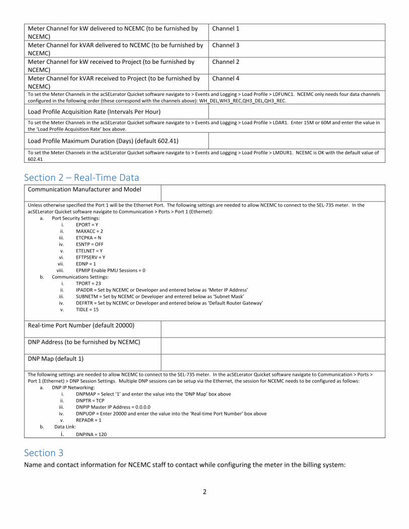
Meter Channel for kW delivered to NCEMC (to be furnished by NCEMC)
Channel 1
Meter Channel for kVAR delivered to NCEMC (to be furnished by NCEMC)
Channel 3
Meter Channel for kW received to Project (to be furnished by NCEMC)
Channel 2
Meter Channel for kVAR received to Project (to be furnished by NCEMC)
Channel 4
To set the Meter Channels in the acSELerator Quicket software navigate to > Events and Logging > Load Profile > LDFUNC1. NCEMC only needs four data channels configured in the following order (these correspond with the channels above): WH_DEL,WH3_REC,QH3_DEL,QH3_REC.
Load Profile Acquisition Rate (Intervals Per Hour)
To set the Meter Channels in the acSELerator Quicket software navigate to > Events and Logging > Load Profile > LDAR1. Enter 15M or 60M and enter the value in the ‘Load Profile Acquisition Rate’ box above.
Load Profile Maximum Duration (Days) (default 602.41)
To set the Meter Channels in the acSELerator Quicket software navigate to > Events and Logging > Load Profile > LMDUR1. NCEMC is OK with the default value of 602.41
Section 2 – Real-Time Data Communication Manufacturer and Model
Unless otherwise specified the Port 1 will be the Ethernet Port. The following settings are needed to allow NCEMC to connect to the SEL-735 meter. In the acSELerator Quicket software navigate to Communication > Ports > Port 1 (Ethernet):
a. Port Security Settings: i. EPORT = Y
ii. MAXACC = 2 iii. ETCPKA = N iv. ESNTP = OFF v. ETELNET = Y vi. EFTPSERV = Y
vii. EDNP = 1 viii. EPMIP Enable PMU Sessions = 0
b. Communications Settings: i. TPORT = 23
ii. IPADDR = Set by NCEMC or Developer and entered below as ‘Meter IP Address’ iii. SUBNETM = Set by NCEMC or Developer and entered below as ‘Subnet Mask’ iv. DEFRTR = Set by NCEMC or Developer and entered below as ‘Default Router Gateway’ v. TIDLE = 15
Real-time Port Number (default 20000)
DNP Address (to be furnished by NCEMC)
DNP Map (default 1)
The following settings are needed to allow NCEMC to connect to the SEL-735 meter. In the acSELerator Quicket software navigate to Communication > Ports > Port 1 (Ethernet) > DNP Session Settings. Multiple DNP sessions can be setup via the Ethernet, the session for NCEMC needs to be configured as follows:
a. DNP IP Networking: i. DNPMAP = Select ‘1’ and enter the value into the ‘DNP Map’ box above
ii. DNPTR = TCP iii. DNPIP Master IP Address = 0.0.0.0 iv. DNPUDP = Enter 20000 and enter the value into the ‘Real-time Port Number’ box above v. REPADR = 1
b. Data Link: i. DNPINA = 120
Section 3 Name and contact information for NCEMC staff to contact while configuring the meter in the billing system:

3
Name and contact information for NCEMC staff to contact while configuring the meter in the SCADA system:
Meter IP Address: Subnet Mask: Default Router Gateway:
Section 4 NCEMC Staff member notes relevant to this project: