membranes made with zeolite and zif-8, and their ... application of zeolite membranes for separation...
TRANSCRIPT
Instructions for use
Title Membranes Made with Zeolite and ZIF-8, and Their Applications to Water Separation from Organic/Water Mixtures
Author(s) 張, 雅琪
Issue Date 2016-03-24
DOI 10.14943/doctoral.k12337
Doc URL http://hdl.handle.net/2115/61933
Type theses (doctoral)
File Information Yaqi_Zhang.pdf
Hokkaido University Collection of Scholarly and Academic Papers : HUSCAP

Membranes made with zeolite and ZIF-8, and their applications to
water separation from organic/water mixtures
ゼオライト膜及び ZIF-8 膜の合成と有機物水混合溶液分離への応用
北海道大学大学院 総合化学院
総合化学専攻 プロセス工学講座
Yaqi Zhang
1
Table of Contents
Chapter 1 Introduction
1.1. Development of porous materials and porous materials based membranes 5
1.1.1. Development of porous materials 5
1.1.2. Development of porous materials based membrane 6
1.2. Zeolite molecular sieve 8
1.2.1. Representative structures of zeolites 9
1.2.2. The application of the zeolite 10
1.3. Zeolite membrane 11
1.3.1. Membrane and Membrane process 11
1.3.2. Zeolite membrane 13
1.3.3. Zeolite Membrane synthesis 13
1.3.4. Zeolite membrane characterization 14
1.3.5. The application of zeolite membranes for separation 15
1.4. Pervaporation 18
1.4.1. Pervaporation process 18
1.4.2. Pervaporation mechanism in zeolite membrane 19
1.4.2.1. Adsorption 20
1.4.2.2. Diffusion 20
1.4.3. The advantage and application of pervaporation 21
1.5. Zeolitic imidazolate frameworks (ZIFs) 22
1.5.1. Synthesis of ZIF crystals 24
1.5.1.1. ZIFs synthesis with solvent 24
1.5.1.2. ZIFs synthesis without solvent 25
1.5.2. Application of ZIF materials 25
1.5.2.1. Separation 26
1.5.2.2. Catalyst 26
1.5.2.3. Sensing and drug delivery 27
1.6. Preparation methods of ZIFs based membranes 28
1.6.1. In situ preparation method 28
2
1.6.2. Second growth preparation method 29
1.6.3. Counter diffusion preparation method 29
1.7. Research objective 30
References 32
Chapter 2 Mordenite nanocrystal-layered membrane preparation 39
2.1. Introduction 39
2.2. Experimental 40
2.2.1. Nanometer size Mordenite crystals synthesis 40
2.2.2. Preparation of mordenite nanocrystal-layered membranes 40
2.2.3. Analysis methods 41
2.2.4. Pervaporation trials 41
2.3. Results and Discussion 42
2.3.1. Mordenite nanocrystal-layered membrane preparation 42
2.3.2. Performance of mordenite nanocrystal-layered membranes in the
pervaporation experiment 43
2.3.3. Effect of nanocrystal layer thickness on membrane preparation 45
2.3.4. The acid-stability of the mordenite membrane 47
2.4. Conclusions 47
References 47
Chapter 3 Optimization of Mordenite nanocrystal-layered membrane
for dehydration by pervaporation 50
3.1. Introduction 50
3.2. Experimental 50
3.2.1. Preparation of mordenite nanocrystal-layered membranes 50
3.2.2. Analysis methods 51
3.2.3. Pervaporation trials 51
3.3. Results and Discussion 53
3.3.1. Effect of hydrothermal temperature on membrane preparation 53
3.3.2. Effect of organic polarity in feed on water and organic solvent permeation 55
3.3.3. Effects of pre-aging and heating rate for synthesis of the protection
layer on performance of mordenite nanocrystal-layered membranes 55
3.4. Conclusions 61

3
References 62
Chapter 4 MTW nanocrystal-layered membrane preparation 63
4.1. Introduction 63
4.2. Experimental 64
4.2.1. Preparation of MTW zeolite powders 64
4.2.2. Preparation of MTW nanocrystal-layered membranes 64
4.2.3. Pervaporation trials 65
4.3. Results and Discussion 67
4.3.1. MTW nanocrystals synthesis with different Si/Al ratios 67
4.3.2. MTW zeolite nanocrystals membrane synthesis with different OSDAs 68
4.3.3. Effects of the mother liquid concentration of hydrothermal synthesis
on MTW zeolite nanocrystal-layered membrane preparation 70
4.3.4. The acid-stability of the MTW zeolite nanocrystal-layered membranes 73
4.4. Conclusions 75
References 75
Chapter 5 Optimization of MTW zeolite for dehydration by pervaporation 77
5.1. Introduction 77
5.2. Experimental 78
5.2.1. Preparation of MTW nanocrystal-layered membranes 78
5.2.2. Pervaporation trials 79
5.3. Results and Discussion 80
5.3.1. Effect of crystal size in the protection layer on separation properties 80
5.3.2. Effects of the Si/Al ratio on the membrane performance 82
5.3.3. Effect of the nanocrystal layer thickness on membrane
permeation properties 84
5.4. Conclusions 86
References 86
Chapter 6 Preparation of nanocrystal-layered ZIF-8 membrane and
application for separation 88
6.1. Introduction 88
4
6.2. Experimental 88
6.2.1. Synthesis of ZIF-8 membranes 88
6.2.2. Analysis method 89
6.2.3. Pervaporation trials 89
6.3. Results and Discussion 91
6.3.1. Synthesis nanometer size 91
6.3.2. ZIF-8 membrane preparation by second growth method 94
6.3.3. Optimization of ZIF-8 membrane preparation 95
6.3.4. The density of the nanocrystal layer 96
6.3.5. Separation performance of ZIF-8 membrane 97
6.4. Conclusions 98
References 98
Summary 100
Outlook 103
Acknowledements 106
Study Achievements 107
Chapter 1
Introduction
5
Chapter 1
Introduction
1.1. Development of porous materials and porous ma1terials based
membranes
1.1.1. Development of porous materials
A porous material is a material containing pores. The atoms, ions and molecules
which composed in the porous material distribute at the surface and throughout the bulk
of the material. The types and performances of the porous materials are decided by their
porosity, the size, volume and distribution of the porous space and atomic molecular
structure.
Porous materials can be grouped into three classes based on their pore diameter
(φ): microporous, φ<2.0 nm; Mesoporous, 2.0<φ<50 nm; and macroporous, φ> 50nm
[1].
Porous materials attracted wide attention for application of adsorbents, catalysts,
molecular sieves and ion exchangers due to their particular characteristic such as high
surface area, homogeneous pore size. Among all of the porous materials, zeolite is most
studied because of the uniform pore size and well-ordered structure. The uniform pore
size of zeolite can efficiently separate molecules based on the size or shap differences,
namely, selectively separate a small molecule from a bigger one. On the other hand, the
hydrophobicity and hydrophility of the zeolite which decided by the atoms composed in
zeolite is important [2]. The zeolite comprising pure silica can absorb organic molecules
from water, whereas zeolite comprising aluminosilicate can absorb water from organic
solvents.
The applications of zeolite with microporous were limited in the small size
molecules adsorption and separation due to the basic unit of TO4 (SiO4 and AlO4),
which not suitable for the catalysis or adsorption of big organic and biological
molecules [3, 4]. ExxonMobil discovered mesoporous zeolite called M41S in the early
1990s [5], opened new appraches to synthesize catalysts for reaction of relative large
molecules. Mesoporous silicates such as MCM-41 and SBA-15, are porous silicates
with huge surface areas (normally>1000 m2/g), large pore sizes (2 nm < size < 20 nm)
Chapter 1
Introduction
6
and ordered arrays of cylindrical mesopores with very regular pore morphology.
Recently, a new family of microporous material named metal-organic frameworks
(MOFs) has been developed rapidly [6, 7]. In MOFs, the metal ions are connected by
the organic molecules and the frameworks are flexible. MOFs can be obtained by
different synthesis methods, moreover, by adjusting the size and functional groups of
the organic linkers, the surface area and the hydrophilicity or hydrophobility of MOF
structures can be controlled. Hence many researchers invest their attention into MOFs
development in the fields of adsorption, catalysis, storage, separation.
1.1.2. Development of porous materials based membrane
Membranes are widely divided into two parts: polymeric membranes and inorganic
membranes. The polymeric membranes have been well developed because the simple
synthesis method but limited in application since the vulnerability characters. Compared
with the polymeric membranes, inorganic membranes have lots of merits: high pressure
resistance; low activation energy; easy to cleaning.
Inorganic membranes generally include 2 primary categories according to the
structure: pore and dense inorganic membrane. Applications of dense inorganic
membranes are majorly used for low molecular weight gases separation. Porous
inorganic membranes possess more merits than other kinds of membranes which
playing a predominance role in commercial membrane market. Four types of inorganic
materials attracted widest attentions: metallic membrane, ceramic membrane, carbon
membranes and zeolitic membranes [8].
Dense inorganic membranes are usually used for hydrogen separation from
gaseous mixtures. The main synthesis method of metallic membrane is by sintering of
metal powders. The dominant material is palladium (Pd) and its alloys, which is highly
soluble and permeable for hydrogen. But the surface of the metal membranes is easily
be poisoned by a carbon-containing source which development is limited.
Ceramic membranes are synthesis by the combine of a metal with anion in the
form of oxide, carbide or nitride. This kind of membrane is chemically stable in high
temperature environment. Therefores, application is major in food, Pharmacy,
bioindustry.
Carbon membranes can be used for gas separation according size sieving. Because
of the uniform porous strcture in the carbon membrane, the membranes can separation
the small size molecule with big size molecule with a high separation factor. Even
differences bewteen two molecules is very small, the separation performance is very
Chapter 1
Introduction
7
good according to the strictly separation by the solid pores in carbon membranes.
Zeolites are composed by Si-Al-O units and possess the micro-size uniform pores
in the crystalline frameworks. The applications of zeolite membranes are mainly in
separation and act as supplymentary to distillation tower or reaction actor. But there are
still some problems when using zeolite membrane to separate small size molecule,
expecially gas mixture separation. During the zeolite membrane preparation, the
non-zeolite pores or defect points are unavoidable among the zeolite crystals. Therefore,
gas fluxes through zeolite membrane are low compared to other inorganic membranes.
Moreover, the zeolite membranes are usually prepared by using template or surfactant to
help zeolite crystal formation. After the synthesis procedure, the membranes need to
calcinate in a high temperature to remove the template. In the high temperature, zeolite
crystal will shink, but the support which made by different materials go on to expansion,
which made membrane broken.
Recently, a new class of materials, MOFs structure are studied and developed.
MOFs structures contain single metal atoms connected with elongated organic
molecules as ligand. MOFs can be made with millions of different combinations of
metal atoms, molecules and structure. Zeolite imidazolate frameworks (ZIFs) are a
subclass of MOFs. The membranes prepared by using ZIFs materials are interesting for
gas storage and molecular separation [9-10].
Metallic membrane, ceramic membrane, carbon membranes and zeolitic
membranes possess the same metrits such as metallic membrane, ceramic membrane,
carbon membranes and zeolitic membranes. However in the past, the application of
inorganic membranes is mainly focus on porous ceramic membranes [11]. Nowadays all
kinds of application have been found and examples of important applications are [12]:
Separation of H2 from coal-derived gas.
Separation of CO2 from natural gas and coal plant flue gas.
Separation of O2 from air for use in efficient combustion, and (petro-) chemical
applications.
The applications of membrane are classified according to their connected pore size.
Dense and micro-porous membranes are applied for gas and liquids separation but can
be permeable for single molecules. Zeolite MFI membrane could use for p/o-xylene
separation [13] and Zeolite A membranes have been commercialized for the removal of
water from organic solution [14] selective transport in dense and micro-porous materials
occurs by a diffusion mechanism.
Meso-porous membrane can be used for selective permeate of ions and small
molecules in liquids by nano-filtration [15]. Supported meso-porous r-alumina

Chapter 1
Introduction
8
membranes have been used for 235
U isotope enrichment. Gas phase transport in
meso-porous membrane occurs by a Knudsen mechanism but liquids transport is
generally by viscous flow.
Macro-porous membranes are commercially available for water filtration
applications. These structures are sometimes used as support for gas separation
membranes. Both gas and liquid phase transport in macro-porous membrane occurs by
viscous flow.
1.2. Zeolite molecular sieve
Zeolites are derived from natural volcanic minerals with unique performances,
especially when the volcanic ash diffused in ancient alkaline water areas, the salts media
altered and rebuilt the ash into different zeolite materials [16].
Zeolites are 3D microporous crystals which contain Al, Si and O in the regular
frameworks [17]. The corresponding crystallographic structure is formed by tetrahedras
of (AlO4) and (SiO4). Figure 1.1 shows the typical tetrahedral structures. They are the
basic building blocks of zeolites. Since the network of SiO4 tetrahedral is neutral and
AlO4 tetrahedron in the framework takes a negative charge, zeolite frameworks need to
combine with charge compensating cations (Na+, K
+ or NH
4+) to maintain electrical
neutrality.
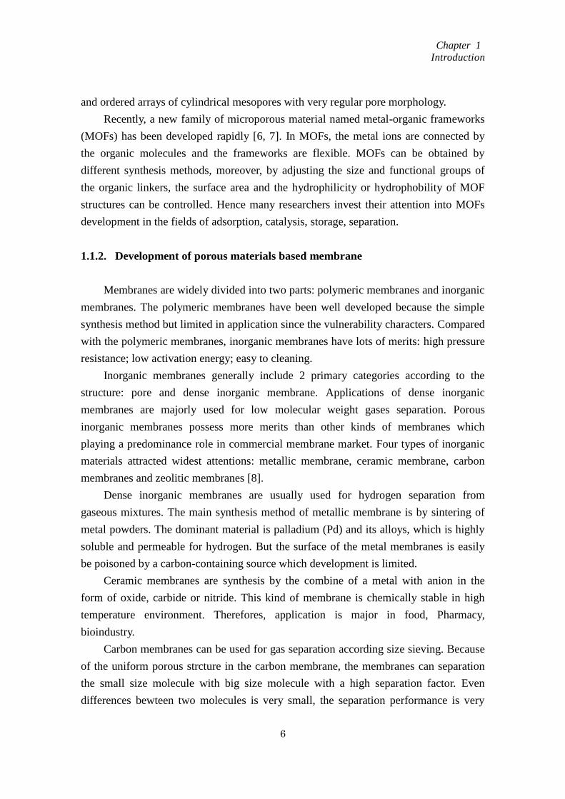
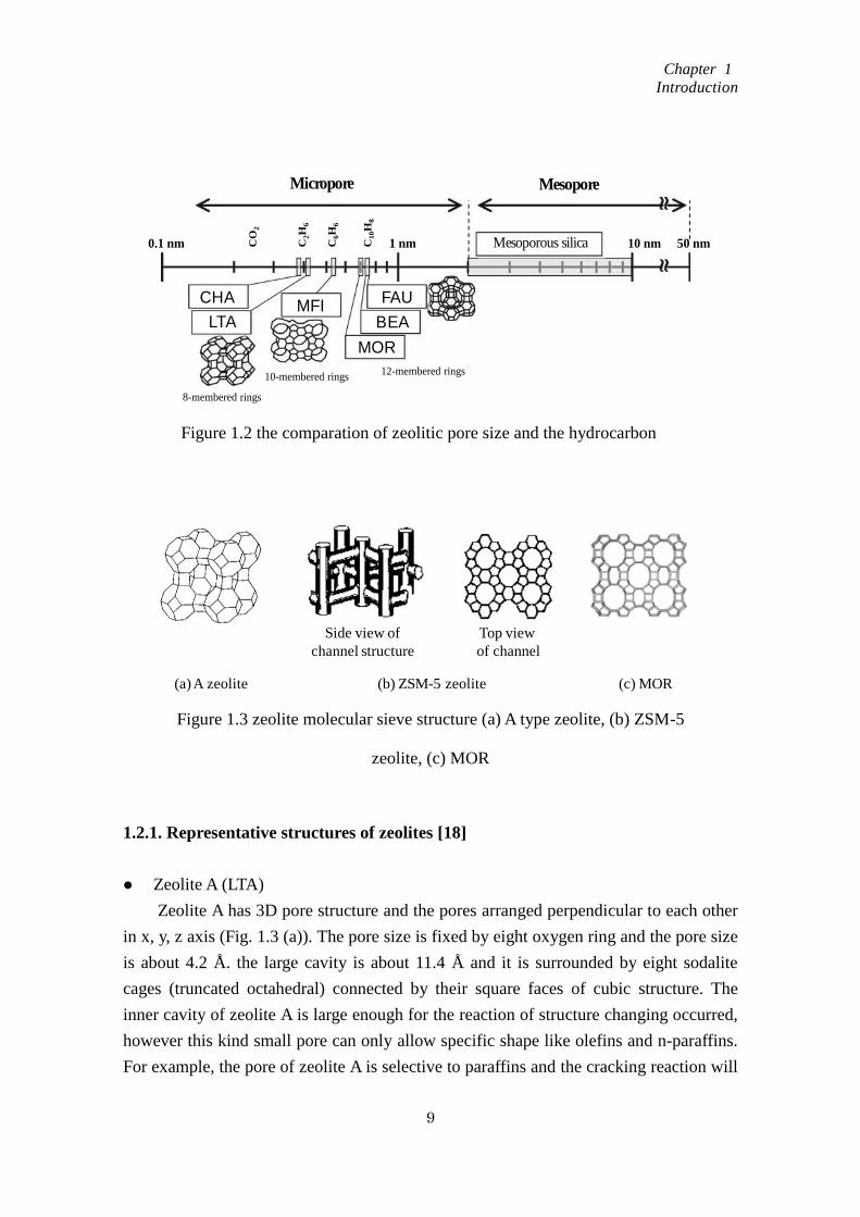
The zeolite framework includes channels, channel intersections and cages, which
are agree with the dimensions range of most molecules. According to pore size, most
zeolites can be divided into three species (Fig. 1.2): small pore zeolites of 8 membrane
ring apertures, e.g. zeolite A; medium pore zeolites with 10 membrane ring apertures,
e.g. zeolite ZSM-5 and large pore zeolites with 12 membrane ring apertures, 6.0-8.0 Å
e.g. zeolite MOR.
Figure 1.1 Tetrahedron-Basic building units of zeolites
Al δ- Si Si
OO O
H δ+O
O
O
O
T
T=Si or Al
Chapter 1
Introduction
9
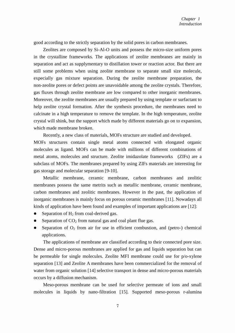
1.2.1. Representative structures of zeolites [18]
Zeolite A (LTA)
Zeolite A has 3D pore structure and the pores arranged perpendicular to each other
in x, y, z axis (Fig. 1.3 (a)). The pore size is fixed by eight oxygen ring and the pore size
is about 4.2 Å. the large cavity is about 11.4 Å and it is surrounded by eight sodalite
cages (truncated octahedral) connected by their square faces of cubic structure. The
inner cavity of zeolite A is large enough for the reaction of structure changing occurred,
however this kind small pore can only allow specific shape like olefins and n-paraffins.
For example, the pore of zeolite A is selective to paraffins and the cracking reaction will
Figure 1.2 the comparation of zeolitic pore size and the hydrocarbon
0.1 nm
8-membered rings
CHA
LTAMFI
FAU
BEA
MOR
10-membered rings12-membered rings
Mesoporous silica1 nm 10 nm 50 nm
Micropore Mesopore
ゼオライトの細孔径
CO
2
C2H
6
C6H
6
C1
0H
8
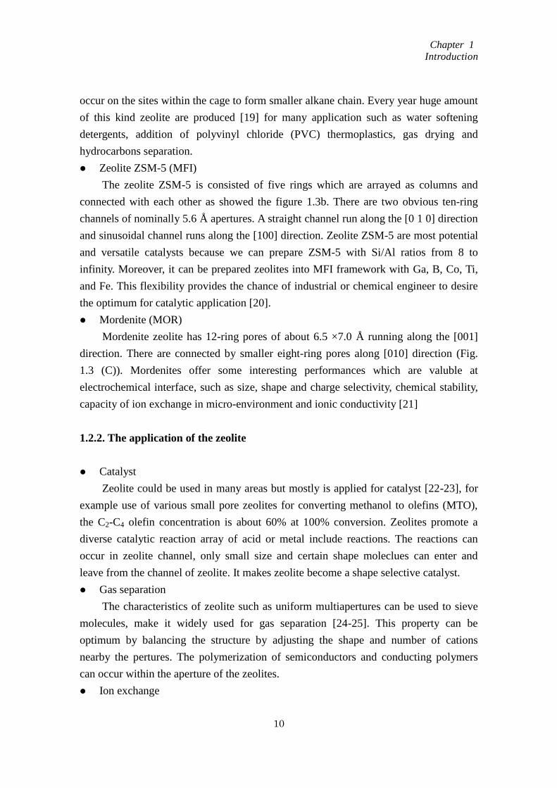
Figure 1.3 zeolite molecular sieve structure (a) A type zeolite, (b) ZSM-5
zeolite, (c) MOR
(a) A zeolite (c) MOR(b) ZSM-5 zeolite
Top view
of channel
Side view of
channel structure
Chapter 1
Introduction
10
occur on the sites within the cage to form smaller alkane chain. Every year huge amount
of this kind zeolite are produced [19] for many application such as water softening
detergents, addition of polyvinyl chloride (PVC) thermoplastics, gas drying and
hydrocarbons separation.
Zeolite ZSM-5 (MFI)
The zeolite ZSM-5 is consisted of five rings which are arrayed as columns and
connected with each other as showed the figure 1.3b. There are two obvious ten-ring
channels of nominally 5.6 Å apertures. A straight channel run along the [0 1 0] direction
and sinusoidal channel runs along the [100] direction. Zeolite ZSM-5 are most potential
and versatile catalysts because we can prepare ZSM-5 with Si/Al ratios from 8 to
infinity. Moreover, it can be prepared zeolites into MFI framework with Ga, B, Co, Ti,
and Fe. This flexibility provides the chance of industrial or chemical engineer to desire
the optimum for catalytic application [20].
Mordenite (MOR)
Mordenite zeolite has 12-ring pores of about 6.5 ×7.0 Å running along the [001]
direction. There are connected by smaller eight-ring pores along [010] direction (Fig.
1.3 (C)). Mordenites offer some interesting performances which are valuble at
electrochemical interface, such as size, shape and charge selectivity, chemical stability,
capacity of ion exchange in micro-environment and ionic conductivity [21]
1.2.2. The application of the zeolite
Catalyst
Zeolite could be used in many areas but mostly is applied for catalyst [22-23], for
example use of various small pore zeolites for converting methanol to olefins (MTO),
the C2-C4 olefin concentration is about 60% at 100% conversion. Zeolites promote a
diverse catalytic reaction array of acid or metal include reactions. The reactions can
occur in zeolite channel, only small size and certain shape moleclues can enter and
leave from the channel of zeolite. It makes zeolite become a shape selective catalyst.
Gas separation
The characteristics of zeolite such as uniform multiapertures can be used to sieve
molecules, make it widely used for gas separation [24-25]. This property can be
optimum by balancing the structure by adjusting the shape and number of cations
nearby the pertures. The polymerization of semiconductors and conducting polymers
can occur within the aperture of the zeolites.
Ion exchange

Chapter 1
Introduction
11
Zeolite acted as ion exchange, is maimly applicated in toothpaste, water softening,
soaps and detergents fields because of the hydrated cations within the zeolite pores can
exchange with other cations when in water solutions.
1.3. Zeolite membrane
1.3.1. Membrane and Membrane process
Membrane can be used for two phase`s separation; selective separation is the main
function of a membrane and membrane process. Membranes can be classified into two
parts: biofilm and prepared membranes. The biofilm like liposomes and vesicles are
now applied in pharmaceutical industry. Prepared membranes can be subdivided into
organic and inorganic membranes. In accordance with specific condition, the membrane
can be prepared differently in morphology, thickness, homogeneous and heterogeneous.
By changing the opration condition such as pressure, concentration or a temperature, the
membrane prosess can be transformed from active to passive..
The properties and characterization of the membrane decide membranes`
application. The structural of membrane materials, the pore size of the membrane
materials and even the distribution of the pore in the membrane affect the membrane
characterization and the application of the membranes
Membrane separation means using permeable membrane to transport of substances
between two fractions. Because the operation which carried in the membrane separation
process without heating, therefore the separation using membrane is less energy than
conventional thermal separation process.
According to the separation system, the membrane separation process can be
divided into three types: microfiltration separation, ultrafiltration and reverse osmosis
separation [26].
When the diameter of particles is smaller than 100 nm and it is act as permeate
component, the high flux could be obtained only with low hydrodynamic resistance and
small driving forces. This kind of membrane process is called micro size particle
filtration.
Ultrafiltration can be used to separate the macro size molecules. Compared with
the microfiltration, the increased in permeate resisitance of bigger size particles need
larger driving force to meet the separation requirement.
When the separation system is the small molecular weight and the molecule size of
the two components is nearly the same, the high dense membrane is needed and during
Chapter 1
Introduction
12
the separation process, a high hydrodynamic resistance will exist and this process can
be defined as reverse osmosis.
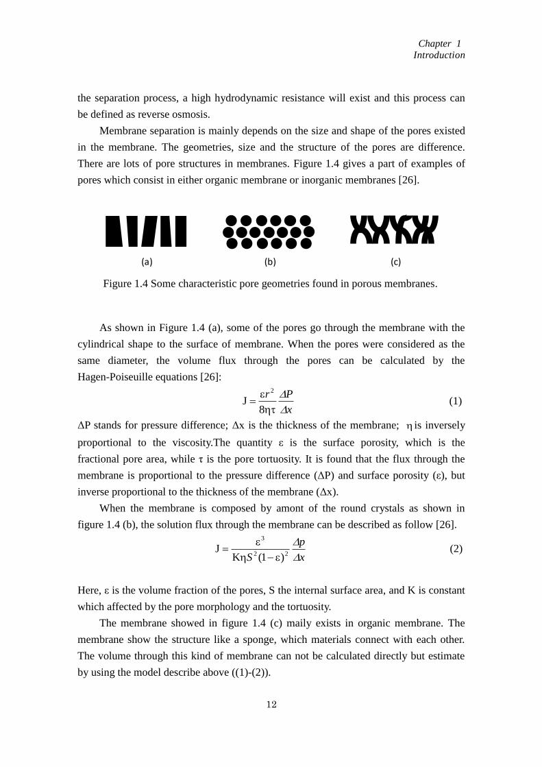
Membrane separation is mainly depends on the size and shape of the pores existed
in the membrane. The geometries, size and the structure of the pores are difference.
There are lots of pore structures in membranes. Figure 1.4 gives a part of examples of
pores which consist in either organic membrane or inorganic membranes [26].
As shown in Figure 1.4 (a), some of the pores go through the membrane with the
cylindrical shape to the surface of membrane. When the pores were considered as the
same diameter, the volume flux through the pores can be calculated by the
Hagen-Poiseuille equations [26]:
x
Pr
8J
2
(1)
ΔP stands for pressure difference; Δx is the thickness of the membrane; is inversely
proportional to the viscosity.The quantity ε is the surface porosity, which is the
fractional pore area, while τ is the pore tortuosity. It is found that the flux through the
membrane is proportional to the pressure difference (ΔP) and surface porosity (ε), but
inverse proportional to the thickness of the membrane (Δx).
When the membrane is composed by amont of the round crystals as shown in
figure 1.4 (b), the solution flux through the membrane can be described as follow [26].
x
p
S
22
3
)1(KJ
(2)
Here, ε is the volume fraction of the pores, S the internal surface area, and K is constant
which affected by the pore morphology and the tortuosity.
The membrane showed in figure 1.4 (c) maily exists in organic membrane. The
membrane show the structure like a sponge, which materials connect with each other.
The volume through this kind of membrane can not be calculated directly but estimate
by using the model describe above ((1)-(2)).
Figure 1.4 Some characteristic pore geometries found in porous membranes.
(a) (b) (c)
Chapter 1
Introduction
13
1.3.2. Zeolite membrane
Zeolites are crystalline microporous aluminasilicates which built up by a three
dimensional network of SiO4 and AlO4 retrathedra [27]. Zeolites have been used for as
toothpaste, adsorbent and catalysts. However, the most fundamental application by
zeolite is molecular sieving. The zeolite membrane separation mainly based on the
molecule size and shape selective separation. The molecule with a kinetic diameter too
large to pass through the zeolite internal adsorption surface will be effectively sieved.
Table 1.1 shows some properties of zeolites [28, 29]. Zeolite LTA is a very hydrophilic
zeolite because of a high amount of aluminium contains. The pore size is dependent on
the type of the cation and Ca2+
, Na+ and K
+ gives 5A, 4A and 3A, respectively. On the
other hand silicalite-1 is a very hydrophobic zeolite since without aluminium contain.
Specific separation can be operated when use the zeolite as a material for membrane
synthesis [30-35].
1.3.3. Zeolite Membrane synthesis
Typically, a zeolite membrane is prepared by hydrothermal synthesis under a high
temperature or pressure in a traditional autoclave. For membrane synthesis, the silica
source and aluminum source are mixed together and add in to water alkaline solution.
Some time the surfactants or templates such as structure directing agents are also used
to help crystal formation, and after the membrane synthesis, the template can be deleted
by calcination methods. The pH of the mother liquids, the ratio of silica by alumina and
the ratio of metal ion and silica are the important factors affect membrane preparation.
There are all kinds of zeolite membrane synthesis methods and they were been
conclude as follow:
In situ hydrothermal synthesis methods
“In situ hydrothermal synthesis” means synthesize a membrane only in one step.
During the hydrothermal synthesis, the alumina filter which acting as membrane
support is immersed in the mother solution, the nucleation on the surface of alumina
filter is requied. The crystal nucleus can grow into the zeolite crystals at a high
temperature and high pressure condition [36, 37].
Ex situ hydrothermal synthesis or second growth methods
The method which using the seed to synthesis membrane was first appear in 1993
[38], and follow the patent was submitted in 1994 [39]. This method includes two
synthesis steps. The first step is formation of the first layer of the membrane on the
Chapter 1
Introduction
14
surface of the membrane support by adsorbing the same zeolite as seed crystals. These
first layer seed crystals will further growth under hydrothermal synthesis condition in
the second stage. Since it is easy for the neclei get growth than the neclei formation,
therefore, the crystal growth take place from the existed seed and the nucleation from
the mother liquid decreased. There are some merits of the method about ex situ
hydrothermal synthesis methods likes: firstly, the purity of crystallization is increased
and in some extent to prevent the formation of the zeolite crystal into the support pores
[40]. Secondly, the second growth method can keep the nuclei at the same growth rate
as well as the crystal growth directions. In generally, the membrane prepared by second
growth method usually showed the c-orientation [41, 42]. However the b-orientation
membrane was also successfully prepared by Lai et al. [43], and the membranes they
prepared shown high separation performance [44, 45].
Other synthesis methods
Microwave-assisted crystallization provides an efficient method for preparing the
zeolite membrane in short times [46]. The zeolite crystallization process was carried out
by using microwaves for heating the autoclaves. There were all kinds of zeolite have
been successfully synthesis by using this method [47-50].
1.3.4. Zeolite membrane characterization
Some of the methods can be used to analysis the zeolite characterization such as:
scanning electron microscopy (SEM), X-ray diffraction (XRD), X-ray Fluorescence
Analysis (XRF), energy dispersive X-ray spectroscopy (EDS).
SEM can be used to observe membrane morphology and the thickness of the
membrane. The membrane quality and layer uniformity can also be checked by
observing the crystal size, shape and the connection between the crystals.
XRD can measure the zeolite crystallinity. During the membrane preparation
process, some zeolite powder also formed in the mother liquid and become deposit.
Since these crystals show similar to the membranes, they can used to make XRD
analysis to determine the membrane`s crystallinity purity.
EDS is used to check zeolite composition and usually with help of XRF. In zeolite
membrane, the alumina contains ratio in the membrane is important factor affect
membrane performance, and this alumina ratio can be detect using EDS analysis. Some
reasearchers also use EDS to check the mix area of the membrane and membrane
support [51, 52].
The property of the membrane is usually checked by the separation experiments.
Chapter 1
Introduction
15
For usually, membrane separation is used for gas mixtures or liquid mixtures separation.
Gas separation mainly depends on the size sieving. For an ideal membrane, small size
molecule can go through the pore of the membrane, but big size molecule is left on the
feed side. The pressure acts as driving force for gas separation. But some materials`
frameworks are flexible which can be permeated by bigger molecules.
Compared with sigle gas permeation, some mixtures permeate are different. The
reason include two aspects: the partial pressure is different and there is competitive
adsorption among the gas mixtures in feed side. N-C4H10/i-C4H10 could be separated by
using 10-membrane ring (MR) zeolite membrane [53]. Small pore, such as 8 MR zeolite
membranes can be characterized by separation of light gas, like H2/CH4 [54], CO2/CH4
[55] or H2/N2 [56].
Separation by pervaporation usually refers to liquid mixture separation. Different
with gas separation, liquid separation is not only depends on molecule size sieving but
also hydrophilic and hydrophobic ability of molecules. During the pervaporation, small
size molecules which possess high polarity will adsorb on the surface of the membrane
and go through the membrane, at last get vaporization at permeate side. The driving
force for liquid mixture separation is partical concentration which refered by using
vacuum or carried gas at permeate side. The section 1.4 will give further discussion.
1.3.5. The application of zeolite membranes for separation [57]
Gas separation
The gas separation is mainly conducted by polymeric membranes. However, in the
separation process of refining, petrochemical, and nature gas industries, zeolite
membranes still have large opportunities since they are more robust to support high
partial pressure.
Zeolite membranes for gas separations are mainly carried out on the laboratory
scale. MFI zeolite membranes were widely studies because of their pores sizes (0.55
nm) are suitable for gas separation of many industrial mixtures.
Table 1.2 summarizes some results concerning gas separation.
Alcohol dehydration
A mixture of two or more liquids whose proportions cannot be altered by simple
distillation is an azeotrope. Azeotropic separation usually refers to the specific
techniques and pervaporation by using zeolite membranes is one of the choices.

Chapter 1
Introduction
16
A-type zeolite membrane is most commonly employed for separation water from
organic mixtures, because they are highly alumina contents and has a small pore, which
is little larger than water molecular but smaller than most of organic moleculars. Many
researchers have attempted to synthesize the A-type membrane and using them for
organic dehydration by pervaporation method. Table 1.3 shows the result of the
experiments. Usually the water flux through the membrane is affected by the
concentration of water in the feed side and pervaporation temperature. because water
flux through the membrane depends on the driving force which separation system refer.
However, the temperature has little effect on the separation factor of the membranes.
The Si/Al ratio in A type zeolite is low. Therefore, A type zeolite displays high
hydrophilicity which can be used for dehydration of alcohols. But the generally the
fluxes and separation factor is lower than A-type zeolite because their Si/Al ratio is
lower showed lower hydrophilicity.
Table 1.2 Gas separation results with zeolite membranes
Table 1.3 Pervaporation performance of zeolite NaA in alcohol dehydration

Chapter 1
Introduction
17
Except A-type zeolite, zeolite X, Y, ZSM-5, MOR and T also been used in the
dehydration of alcohols. But the generally the fluxes and separation factor is lower than
A-type zeolite because their Si/Al ratio is lower showed lower hydrophilicity.
Acid solution dehydration
The separation water from the esterification reaction for equilibrium, and the acid
solution dehydration required an acid resistant hydrophilic membrane. However,
hydrophilic zeolite is not stable in acid solution, since the alumina-oxygen bond is
broken easily in acid solution. The zeolite T, MOR, and ZSM-5 were invested for
water/acid mixture separation, MOR and zolite T show the high water permeability.
Both of MOR and T zeolite possess 12 membrane ring which providing alternate
pathways for H2O but organic molecular could not permeate.
High slica contents membrane silicalite-1 membrane can also used for water/acetic
acid mixtures separation. The membranes need some post treatment before using for
separation. Our laboratory has been focus on this study for a long time. It is founded
that the (-OH) group which on the surface of the zeolite membrane help for zeolite
membrane separation and not destroyed by acid solution. The channel for water
separation is not only include zeolite pore in the zeolite frameworks, but also the
zeolitic-pores among the zeolite crystals.
Organic separation
Separation of organic molecules from water required using hydrophpbic
membranes. Among those membranes, silicalite-1, ZSM-5, and β type zeolite were
mostly studied. Compare with the hydrophilic zeolite membrane, hydrophobic
membranes possess low permeability and separation ability. This is because organic
molecular is larger than water molecular and easily diffuse through the membrane.
Separation is only depend on the hydrophobility zeolite preferentially adsorb organic
molecular. Non-zeolitic pores and structure defects decrease the membrane separation
ability.
Bowen` group [66] studied the separation ability of Ge-ZSM-5 membrane by
separation organic compounds from organic/water mixtures. The result shows that the
separation ability and flux are proportion to the organic component` fugacity in the
mixture.
Organic/Organic separation
Methy-tert-butyl ether (MTBE) can be used as an additive in gasoline, however as
a potential human carcinogen, the separation MTBE from the mixture and safely
discharge attracted much interest in the industries. The separation of MEOH from
MTBE can be conducted by using zeolite silicalite-1 [67] and X, Y type zeolite
Chapter 1
Introduction
18
membranes. Zeolite Y and X showed good results in the separation process. NaY zeolite
membranes were prepared by a research group and are used to separation the
methanol/MTBE solution, it was found that different with other kinds of membrane, the
separation factor decreased when increase the permeate molecule concentration
(methanol molecule).
1.4. Pervaporation
In chemical industry and chemical processes, a separation is one of most important
unit operation, which is mainly carried out by distillation. In high purity separation by
distillation, the number of trays as well as the reflux ratio increase. Moreover, the
azeotropic distillation such as water/ethanol, 3rd component of benzene need to be
added in the distillation system, which is complex process with large energy
consumption. It is important to build a new separation process composed of a
distillation tower and other separation method. After separation by a distillation at a
certain level, further purification is carried out by the new separation method, by which
enable us to reduce energy consumption and to design a simple separation process. One
method is prevaporation.
1.4.1. Pervaporation process
Pervaporation is a process method for separation of mixture of liquids by selective
sorption and diffusion of a component through the membrane. Different from other
separation process, there is a phase change during the pervaporation process.
Binning et al. [69] described the pervaporation process by the solution-diffusion
mechanism. The pervaporation process can be divided into three steps according to the
model, adsorption, diffusion and evaporation. In the mixture solution, the membrane
adsorbs the components and the adsorbed components diffuse across the membrane
under a chemical potential gradient and get evaporation at the downside of the
membrane.
The adsorption is affected by the organic molecule polarities of the solution and the
size, shape and molecular weight of the solute. The thermodynamic properties are the
driving force during the whole process.
There is not selection during the desorption process. Therefore, the organic
molecules diffuse in the final step of transport and get evaporation from the downside of
the membrane with only small transport thermodynamics activities to be separated.
Chapter 1
Introduction
19
1.4.2. Pervaporation mechanism in zeolite membrane
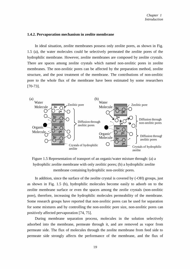
In ideal situation, zeolite membranes possess only zeolite pores, as shown in Fig.
1.5 (a), the water molecules could be selectively permeated the zeolite pores of the
hydrophilic membrane. However, zeolite membranes are composed by zeolite crystals.
There are spaces among zeolite crystals which named non-zeolitic pores in zeolite
membranes. The non-zeolitic pores can be affected by the preparation method, zeolite
structure, and the post treatment of the membrane. The contributions of non-zeolitic
pore to the whole flux of the membrane have been estimated by some researchers
[70-73].
In addition, since the surface of the zeolite crystal is covered by (-OH) groups, just
as shown in Fig. 1.5 (b), hydrophilic molecules become easily to adsorb on to the
zeolite membrane surface or even the spaces among the zeolie crystals (non-zeolitic
pore), therefore, increasing the hydrophilic molecules permeability of the membrane.
Some research groups have reported that non-zeolitic pores can be used for separation
for some mixtures and by controlling the non-zeolitic pore size, non-zeolitic pores can
positively affected pervaporation [74, 75].
During membrane separation process, molecules in the solution selectively
adsorbed into the membrane, permeate through it, and are removed as vapor from
permeate side. The flux of molecules through the zeolite membrane from feed side to
permeate side strongly affects the performance of the membrane, and the flux of
Figure 1.5 Representation of transport of an organic/water mixture through: (a) a
hydrophilic zeolite membrane with only zeolitic pores; (b) a hydrophilic zeolite
membrane containing hydrophilic non-zeolitic pores.
Zeolitic pore
Crystals of hydrophilic zeolite
Diffusion throughnon-zeolitic pores
OrganicMolecule Diffusion through
zeolitic pores
Water
Molecule
OH
OH
OH
OH
OH
OH
OH
OH
Diffusion throughzeolitic pores
Water
Molecule
Organic
Molecule
Crystals of hydrophilic zeolite
OH
OH
OH
OH
OH
OH
OH
OH
(a) (b)
Zeolitic pore
Chapter 1
Introduction
20
molecules through the membrane can be expressed as follow when adsorption of
molecules do follows Langmuir isotherm and effect of counter diffusion could be
ignored [76].
)q(qδ
(0)εDρJ pi,fi,
s
vi,s
i (1)
here, ρs, ε, Dsi,v(0), δ, qi,f, and qi,p are the zeolite membrane density, porosity, the
intracrystalline surface diffusivity, thickness of membrane, quantities of component i on
the feed side and the permeate side, respectively.
1.4.2.1. Adsorption
Adsorption is usually a heat release process. In zeolite membrane, the affinity of
organic molecules and water molecules are decided by the hydrophilic and hydrophobic
ability of the zeolite. Usually, the Si/Al ratio affects the hydrophilicity and
hydrophobicity characters of zeolite, and the Si/Al ratio of the zeolite structure could be
change in a wide range.
For example, Silicalite-1 is the most hydrophobic zeolite since the Si/Al ratio in
silicalite-1 structure equal to infinity, and silicalite-1 could be used to separate the
organic molecules from water. Howerer, zeolite A can be used for organic solution
dehydration because of the hydrophilicity of zeolite A (Si/Al=1).
The hydrophilicity and hydrophobicity of the materials is difficult to description. A
hydrophobicity index (HI) is defined as follow [77], which helping to make
measurement. (qorganic: organic amount adsorbed by a solid; qwater: water amount
adsorbed by a solid)
water
organicHI
q
q (2)
1.4.2.2. Diffusion
The molecules which adsorbed on the surface of membrane can diffuse along the
zeolite pore or non-zeolitic pore, and reach to the downside of the zeolite membrane.
During the diffusion process, the concentration gradient of adsorbed molecules is
considered to be the driving force. The molecule diffusion in zeolite membrane is in the
range of solution-diffusion, molecular sieving, surface diffusion, Knudsen diffusion.
Chapter 1
Introduction
21
When the diameter of permeate molecule is bigger than the diameter of the zeolite pore,
usually, the diffusivity follows an Arrhenius-type equation [78]:
)RT
Eexp(DD d
0 (3)
1.4.3. The advantage and application of pervaporation
By combination with distillation and other rectification processes, pervaporation
has many potential applications and the separation process become simplicity, efficiency
and favorable economics. The advantages of pervaporation can be concluded as follows:
a. The new separation process which combining the distillation and pervaporation is less
cost and low energy demand.
b. The pervaporation can be used in the azeotropes separation.
c. Pervaporation is a green separation technology which freedom from environmental
pollution.
d. Pervaporation can be applied in a wide range according to the membrane properties.
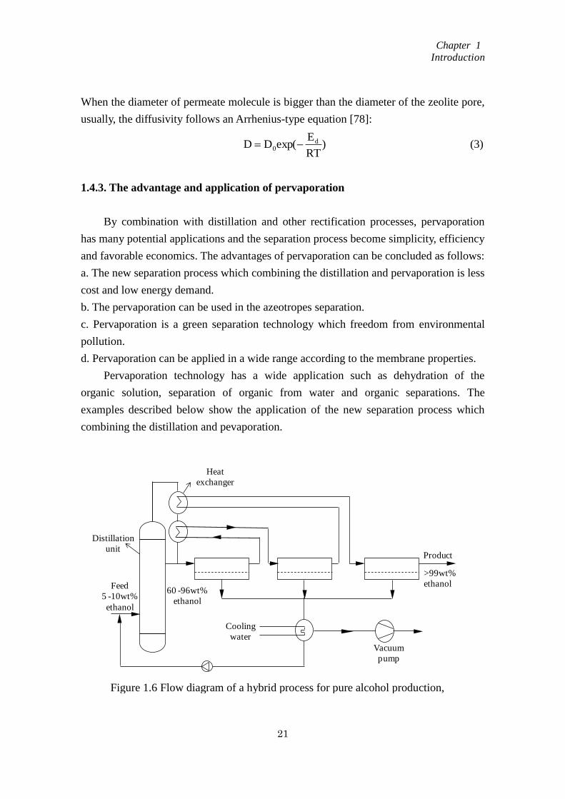
Pervaporation technology has a wide application such as dehydration of the
organic solution, separation of organic from water and organic separations. The
examples described below show the application of the new separation process which
combining the distillation and pevaporation.
Figure 1.6 Flow diagram of a hybrid process for pure alcohol production,
combining distillation with pervaporation.
Product
>99wt%
ethanol
Cooling
water
Vacuum
pump
Heat
exchanger
Distillation
unit
Feed
5 -10wt%
ethanol
60 -96wt%
ethanol
Chapter 1
Introduction
22
Pervaporation technologies are usually used for dehydration of ethanol and
iso-propanol. As show in Figure 1.6, the pervaporation technology and ditllation process
are combined together to separate water from water/ethanol mixtures. The distillation
process can remove bulk of the water and followed by the pervaporation process to
reach 99.8wt% ethanol. By combining the distillation and pervaporation the hybrid
system is less energy consumption. There is only phase change during the pervaporation
need energy consumption. And the retentate steam from the distillation uint can be
reused to offer the energy. In order to enhance the efficiency, the membrane separator
can be divided in small section and connected in series [79].
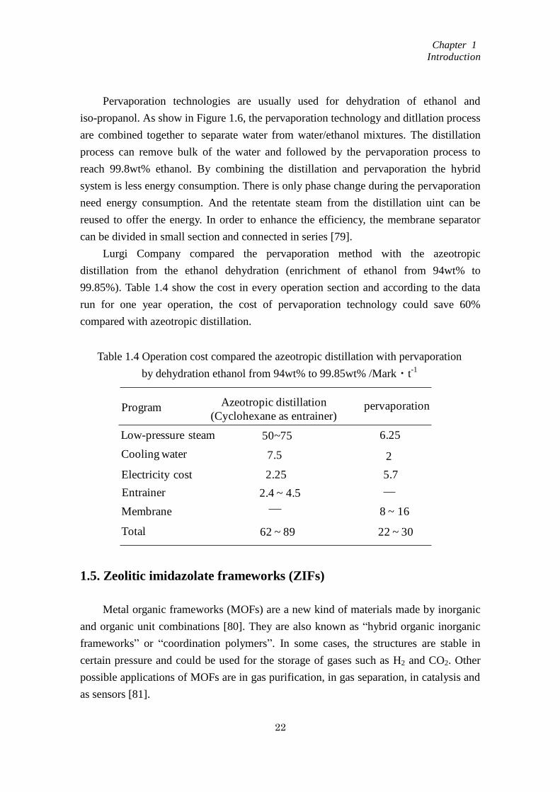
Lurgi Company compared the pervaporation method with the azeotropic
distillation from the ethanol dehydration (enrichment of ethanol from 94wt% to
99.85%). Table 1.4 show the cost in every operation section and according to the data
run for one year operation, the cost of pervaporation technology could save 60%
compared with azeotropic distillation.
1.5. Zeolitic imidazolate frameworks (ZIFs)
Metal organic frameworks (MOFs) are a new kind of materials made by inorganic
and organic unit combinations [80]. They are also known as “hybrid organic inorganic
frameworks” or “coordination polymers”. In some cases, the structures are stable in
certain pressure and could be used for the storage of gases such as H2 and CO2. Other
possible applications of MOFs are in gas purification, in gas separation, in catalysis and
as sensors [81].
Table 1.4 Operation cost compared the azeotropic distillation with pervaporation
by dehydration ethanol from 94wt% to 99.85wt% /Mark・t-1
Program Azeotropic distillation
(Cyclohexane as entrainer)pervaporation
Low-pressure steam
Cooling water
Electricity cost
Entrainer
Membrane
Total
50~75
7.5
2.25
2.4 ~ 4.5
62 ~ 89
6.25
2
5.7
8 ~ 16
22 ~ 30
Chapter 1
Introduction
23
MOFs are made by two parts: inorganic part – a metal ion and organic unit (a
linker) [81]. The combination of inorganic part and organic unit dictates the structure
and hence properties of the MOF. For example, the metal’s coordination preference
influences the morphorlogy of the apertures by determinating the ligand number by
connection with the metals and the connection angle. In MOFs, the framework is
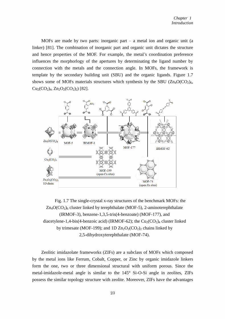
template by the secondary building unit (SBU) and the organic ligands. Figure 1.7
shows some of MOFs materials structures which synthesis by the SBU (Zn4O(CO2)6,
Cu2(CO2)4, Zn2O2(CO2)2) [82].
Zeolitic imidazolate frameworks (ZIFs) are a subclass of MOFs which composed
by the metal ions like Ferrum, Cobalt, Copper, or Zinc by organic imidazole linkers
form the one, two or three dimensional structural with uniform porous. Since the
metal-imidazole-metal angle is similar to the 145° Si-O-Si angle in zeolites, ZIFs
possess the similar topology structure with zeolite. Moreover, ZIFs have the advantages
Fig. 1.7 The single-crystal x-ray structures of the benchmark MOFs: the
Zn4O(CO2)6 cluster linked by terephthalate (MOF-5), 2-aminoterephthalate
(IRMOF-3), benzene-1,3,5-tris(4-benzoate) (MOF-177), and
diacetylene-1,4-bis(4-benzoic acid) (IRMOF-62); the Cu2(CO2)4 cluster linked
by trimesate (MOF-199); and 1D Zn2O2(CO2)2 chains linked by
2,5-dihydroxyterephthalate (MOF-74).
Chapter 1
Introduction
24
of both zeolites and MOFs, such as large surface areas, high crystallinities and
exceptional thermal and chemical stabilities. ZIFs hold great promise in many
application areas including catalysis, separation and sensing [83-85].
1.5.1. Synthesis of ZIF crystals
ZIFs have been rapidly developed and lots of new type ZIFs were synthesis and
named in the past 5 years, traditional method such as hydrothermal synthesis in water or
organic solvents, respectively. The synthesis temperatures range from room temperature
up to 200 °C and reaction time from hours to days. So far, there are two methods have
been developed to synthesis of the ZIF crystals, which ZIFs synthesis with solvent and
ZIFs synthesis without solvent.
1.5.1.1. ZIFs synthesis with solvent
Solvothermal synthesis.
ZIFs, which are synthesis with the organic solvents called solvothermal synthesis.
ZIF-1 to ZIF-12, the twelve kinds of ZIF crystals were firstly prepared by using organic
solvent systems such as N, N-dimethylformamide (DMF), N, N-diethylformamide
(DEF) and N-methylpyrrolidine (NMP) [86]. Other kind of ZIF materials like ZIF-60 to
ZIF-77 [87], ZIF-78 to ZIF-82 [88], ZIF-90 [89] and ZIF-100 [90] were successfully
prepared by using DMF/DEF/NMP as reaction medium solvents. Recently, some
deprotonating agents were added to facilitate the ZIF materials formation, including
some organic amines such as pyridine and triethylamine (TEA). ZIF-78 crystals were
prepared with assistance of TEA [91], while ZIF-90 was prepared with adding of
pyridine to DMF at room temperature [92].
Methanol also can be used as the reaction medium to form ZIFs materials [93].
ZIF-8 crystals can be obtained by using methanol as the reaction medium [94, 95],
moreover, the crystal size and morphology can be controlled by some methods. The
nanosized and hexagonally shaped ZIF-8 crystals can be obtained when using poly
(diallyldimethylammonium chloride) as a stabilizer in methanol [96]. The micron-sized
crystals can be obtained by using modulating ligands such as sodium
formate/1-methylimidazole and n-butylamine in methanol solution [97]. Other alcohols
such as ethanol [98] and isopropyl alcohol [99] were also successfully used as organic
solvents in ZIFs synthesis.
Hydrothermal synthesis
Chapter 1
Introduction
25
The organic solvents are expensive, flammable and not environmentally, recently,
water was used for ZIFs formation [100]. However, the stoichiometric molar ratio of
zinc ions and MIm is high and the large amount usage of MIm was wasted. By adding
the deprotonation agents, the purity ZIFs could be prepared in a low ration of zinc ions
and MIm. Gross et al. [101] prepared ZIF-8 and ZIF-67 in an aqueous system with
addition of TEA at room temperature and the molar ratio of Zn2+
: MIm = 1: 4.
Some surfactants were used to control the ZIFs crystal size and morphology, such
as polyvinylpyrrolidone (PVP). The micron sized ZIF-90 crystals could be obtained in a
water solution by using PVP as surfactant and it was considered that PVP can prevent
the aggregation of crystal seeds to control the morphology and size of the crystals [102].
Moreover, ammonium hydroxide can be used for ZIF-8 formation, the particle sizes and
the structures of ZIF-8 crystals could be easily controlled by change the ammonia
concentration in the synthesis solution [103].
1.5.1.2. ZIFs synthesis without solvent
There are still some problems in the ZIFs formation such as the excessively use
of imidazole sources and the collection of products ZIF-8 needed massive solvent
washing. For this reason, ZIFs formation without usage of solvent has been developed.
Shi et al. [104] obtained ZIF-8 and ZIF-67 by a steam-assisted conversion method.
During the formation process, the solid phase containing metal salts and excess ligands
were placed in a small Teflon cup where surrounded by water vapor at 120 °C for 24h.
Moreover, Zhang et al. [105] have successfully prepared ZIF-8 from the solvent-free
reaction by simply mixing of ZnO and MIm with a molar ratio of 1 : 2, the mixture was
heated at 180 °C for 12 h. Beobibe et al. [106] have also prepared ZIFs by a solvent-free
method, in which ZIFs were formed by the acid-base reaction between
ZnO/CoO/Co(OH)2 and imidazolic ligands at a temperature from 100 °C to 160 °C in a
closed vessel and the high yield of product about 97% were obtained by adding small
amount of structure directing agents.
1.5.2. Application of ZIF materials
ZIFs possess the high porosity, controllable structures and high stable ability even
at a high temperature environment. The application of ZIF materials looks to be
promising. Both ZIF crystals and ZIF membranes have been developed as adsorbents
and catalysts. And even contribute to the fields of sensing and drug delivery.
Chapter 1
Introduction
26
1.5.2.1. Separation
Because of the uniform mutiaperture and superficial area, ZIF materials hold great
potential in gas separation. Both ZIF crystals and ZIF membranes have been widely
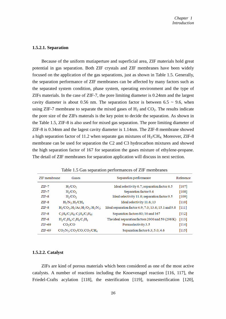
focused on the application of the gas separations, just as shown in Table 1.5. Generally,
the separation performance of ZIF membranes can be affected by many factors such as
the separated system condition, phase system, operating environment and the type of
ZIFs materials. In the case of ZIF-7, the pore limiting diameter is 0.24nm and the largest
cavity diameter is about 0.56 nm. The separation factor is between 6.5 ~ 9.6, when
using ZIF-7 membrane to separate the mixed gases of H2 and CO2. The results indicate
the pore size of the ZIFs materals is the key point to decide the separation. As shown in
the Table 1.5, ZIF-8 is also used for mixed gas separation. The pore limiting diameter of
ZIF-8 is 0.34nm and the lagest cavity diameter is 1.14nm. The ZIF-8 membrane showed
a high separation factor of 11.2 when separate gas mixtures of H2/CH4. Moreover, ZIF-8
membrane can be used for separation the C2 and C3 hydrocarbon mixtures and showed
the high separation factor of 167 for separation the gases mixture of ethylene-propane.
The detail of ZIF membranes for separation application will discuss in next section.
1.5.2.2. Catalyst
ZIFs are kind of porous materials which been considered as one of the most active
catalysts. A number of reactions including the Knoevenagel reaction [116, 117], the
Friedel-Crafts acylation [118], the esterification [119], transesterification [120],
Table 1.5 Gas separation performances of ZIF membranes
Chapter 1
Introduction
27
oxidation [121] alcoholysis [122], and the hydrogen production [123, 124], can be
actively catalyzed by ZIFs.
ZIF-8 can effectively catalyze for the Friedel-Crafts acylation reaction, the anisole
and benzoyl chloride proceeded well by using ZIF-8 and the high product yield was
obtained [118]. Furthermore, ZIF-8 can be used for monoglycerides by esterification of
oleic acid with glycerol. Compared with the reaction without using calalyst (the
conversion is about 10%), the oleic acid conversion is above 50% by using ZIF-8 as a
catalyst. Moreover, ZIF-8 crystals can be easily recovered by filtration methods and can
be reused without losing lots of the activities [119]. Oxidation can also been catalyzed
by ZIFs, for examples, ZIF-9 exhibited catalytic activity for the oxidation of tetralin
[121] and small aromatic molecules such as vanilly alcohol, syringol, and cinnamyl
alcohol [122]. ZIF-9 can also catalyze for the hydrogen production in NaBH4 hydrolysis
reaction. ZIF-9 showed high catalytic activity and thermal stability, the porous structure
of ZIF-9 offer a good support point for Co element. The ZIF-10 and ZIF-8 also act as a
expective materials for calalyze reactions [123].
Moreover, due to the similar characteristic with zeolite materials such as large
surface area and multipoles, some of ZIFs can be used as supports for the incorporation
of various metals to form catalysts [125, 126].
1.5.2.3. Sensing and drug delivery
The high thermal and chemical stabilities of ZIF marterials enable ZIFs to be used
as sensors and even drug deliveries.
ZIFs as the matrix for constructing integrated dehydrogenase electrochemical
biosensors for in vivo measurement of neurochemicals are prepared successfully [127].
In that study, ZIFs act as a matrix for coimmobilizing electrocatalysts and
dehydrogenases onto the electrode surface. Different ZIFs materials were choiced for
the experiment, including ZIF-7, ZIF-8, ZIF-70 which a series of goup marterials with
different pore sizes, channels and functional groups [127]. Based on the luminescence
intensity, ZIF-8 nano-size crystals can be used as a sensing platform for
fluorescence-enhanced detection of nucleic acids [128]. Moreover, caffeine can be
inserted into the ZIF-8 cages [129]. ZIF-8 materials keep stable even in high
temperature, therefore, by combining the caffeine molecules into ZIF-8 cages, the ZIF-8
can control the release of caffeine and provide thermal protection during the high
temperature process.
Chapter 1
Introduction
28
1.6. Preparation methods of ZIF based membranes
ZIF materials possess promising future and can be applied in many areas. ZIF
based membranes using for separation is one of the most attractive applications. So far,
various synthesis methods for ZIF membranes have been studied. Generally, the
synthesis method can be classified into: in situ preparation, secondary growth
preparation and the counter-diffusion preparation.
1.6.1. In situ preparation method
ZIF membrane can be synthesis through one-step solvothermal or hydrothermal
synthesis on the disks or some porous structural support. This kind of method also acted
as a traditional method for zeolite membrane preparation.
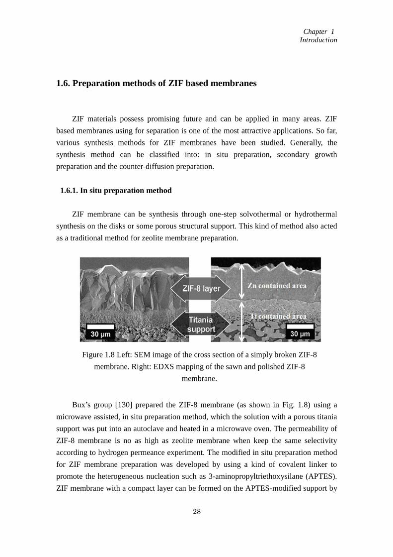
Bux’s group [130] prepared the ZIF-8 membrane (as shown in Fig. 1.8) using a
microwave assisted, in situ preparation method, which the solution with a porous titania
support was put into an autoclave and heated in a microwave oven. The permeability of
ZIF-8 membrane is no as high as zeolite membrane when keep the same selectivity
according to hydrogen permeance experiment. The modified in situ preparation method
for ZIF membrane preparation was developed by using a kind of covalent linker to
promote the heterogeneous nucleation such as 3-aminopropyltriethoxysilane (APTES).
ZIF membrane with a compact layer can be formed on the APTES-modified support by
Figure 1.8 Left: SEM image of the cross section of a simply broken ZIF-8
membrane. Right: EDXS mapping of the sawn and polished ZIF-8
membrane.
Chapter 1
Introduction
29
solvothermal synthesis method such as ZIF-22, ZIF-95 [131-134]. This method makes a
big improvement of membrane quality.
1.6.2. Second growth preparation method
The membrane prepared by second growth method usually realized through two
parts: (1) depositing the crystal seeds by thermal seeding, dip-coating or rubbing; (2)
put the support with the crystal seed layer into the autoclave to go on solvothermal
synthesis or hydrothermal synthesis for the second ZIF membrane layer. The membrane
prepared by this method has the same crystal orientation and the membrane thickness
and grain boundary structure could be controlled by this method.
ZIF-8 membrane was successfully prepared by a second growth method in Carreon
research group [135]. The alumina support was at first seeded with ZIF-8 crystals by
rubbing, then the support with the first layer of the ZIF-8 seed crystals was go on to
hydrothermal synthesis for the second layer formation. In secondary growth methods,
seeding step is very important which decided the membrane quality. The technology to
increase the connection between ZIF crystals and the support is important. Therefore,
many seeding approaches such as reactive seeding [136, 137], pre-coating [138, 139],
and microwave-assisted seeding [140] have been explored.
1.6.3. Counter diffusion preparation method
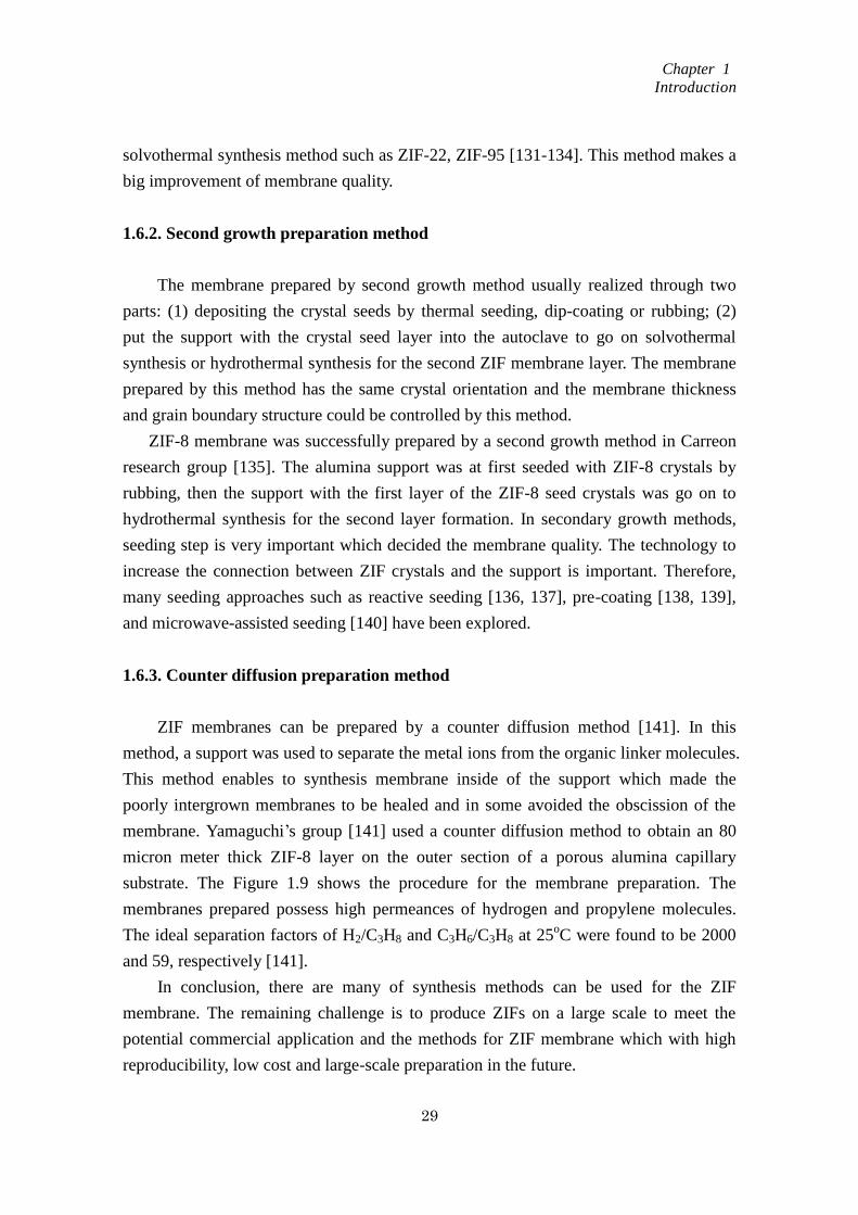
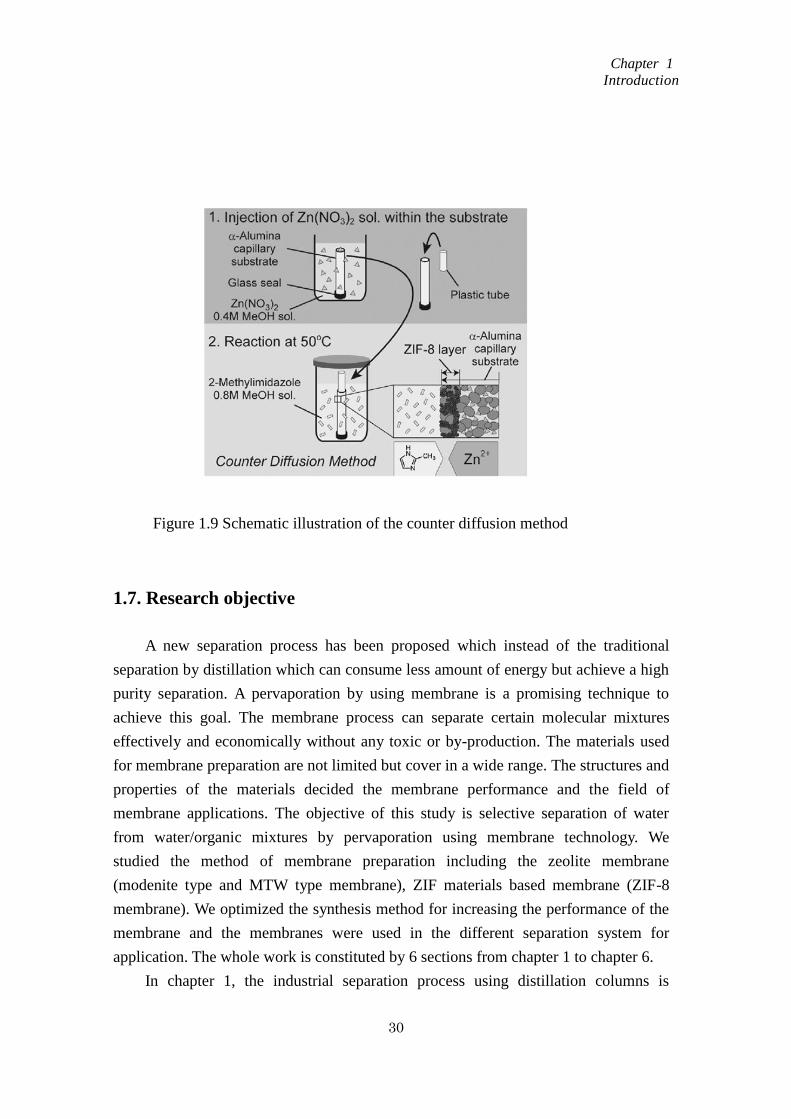
ZIF membranes can be prepared by a counter diffusion method [141]. In this
method, a support was used to separate the metal ions from the organic linker molecules.
This method enables to synthesis membrane inside of the support which made the
poorly intergrown membranes to be healed and in some avoided the obscission of the
membrane. Yamaguchi’s group [141] used a counter diffusion method to obtain an 80
micron meter thick ZIF-8 layer on the outer section of a porous alumina capillary
substrate. The Figure 1.9 shows the procedure for the membrane preparation. The
membranes prepared possess high permeances of hydrogen and propylene molecules.
The ideal separation factors of H2/C3H8 and C3H6/C3H8 at 25oC were found to be 2000
and 59, respectively [141].
In conclusion, there are many of synthesis methods can be used for the ZIF
membrane. The remaining challenge is to produce ZIFs on a large scale to meet the
potential commercial application and the methods for ZIF membrane which with high
reproducibility, low cost and large-scale preparation in the future.
Chapter 1
Introduction
30
1.7. Research objective
A new separation process has been proposed which instead of the traditional
separation by distillation which can consume less amount of energy but achieve a high
purity separation. A pervaporation by using membrane is a promising technique to
achieve this goal. The membrane process can separate certain molecular mixtures
effectively and economically without any toxic or by-production. The materials used
for membrane preparation are not limited but cover in a wide range. The structures and
properties of the materials decided the membrane performance and the field of
membrane applications. The objective of this study is selective separation of water
from water/organic mixtures by pervaporation using membrane technology. We
studied the method of membrane preparation including the zeolite membrane
(modenite type and MTW type membrane), ZIF materials based membrane (ZIF-8
membrane). We optimized the synthesis method for increasing the performance of the
membrane and the membranes were used in the different separation system for
application. The whole work is constituted by 6 sections from chapter 1 to chapter 6.
In chapter 1, the industrial separation process using distillation columns is
Figure 1.9 Schematic illustration of the counter diffusion method
Chapter 1
Introduction
31
intriduced, and its problems are extracted. Furehtmore, the nature of zeolites is
overviewed, and the expection of zeolite membranes is described for a new separation
process.
In chapter 2 and 3, the methods of preparation, optimization of the Mordenite
membranes and application were discussed, respectively. In chapter 2, Mordenite
nanocrystal-layered membranes consisting of a mordenite nanocrystal layer and
protection layer were successfully prepared. The effect of nanocrystal layer thickness
was discussed to determine the appropriate condition for membrane preparation. The
basic conditions were detected in order to use the membrane for pervaporation. The
membrane acid stability was examined by separation of water from acetic acid/water
solution. In chapter 3, four types of water/organic solvent solutions were prepared for
pervaporation experiments using the mordenite nanocrystal-layered membranes to
detect the effect of the polarity of the organic solvent in the feed solution on the
permeance of water through the mordenite nanocrystal-layered membrane. The
mechanism of the mordenite type zeolite membrane was studied and using for
directing the membrane preparation. In order to prepare the membrane with high
separation ability and permeability, the effects of synthesis conditions on the
membranes performance, such as hydrothermal temperature, pre-aging time for the
mother liquid which using for hydrothermal synthesis and heating rate during the
hydrothermal synthesis were discussed. Moreover, the obtained mordenite membranes
were applied to the separation of water from water/organic solutions (organic solvents:
ethanol, acetone, 2-propanol, or acetic acid) using a pervaporation method.
In chapter 4 and chapter 5, a new type high-silica material with a unidimensional
12-membered ring channel were used to prepare the membrane. At first, the MTW
nanocrystals synthesis with different Si/Al ratios and different kinds of the organic
structure directing agent (OSDA) were discussed to dicide the seed crystals for
membrane preparation. A MTW-type zeolite nanocrystal-layered membrane composed
of nanocrystal and protection layers were successfully prepared by a secondary growth
method under hydrothermal conditions. The acidic proof ability of MTW membrane
was detected by separation of water from acetic acid/water solution. Since the MTW
can be synthesized in a wide range of Si/Al and the crystals morphology can be
controlled by using different kind of the OSDA molecules, in chapter 5, the effects of
crystal morphology, Si/Al ratio and thickness of MTW zeolite membrane on
water/2-propanol separation by pervaporation were discussed, respectively. In order to
get better understanding of the membrane preparation and separation, the mechanisms
of the MTW type zeolite membrane were discussed in the chapter. The function of the
Chapter 1
Introduction
32
protection layer and the nanocrystal layer in the membrane separation is studied,
respectively.
In capter 6, zeolitic imidazolate frameworks (ZIFs) as metal-organic frameworks
(MOF) were focused. ZIFs possess the advantages of both zeolites and MOFs,
namely molecular sieving effect, hydrophilic and hydrophobic properties.
Therefores, the nanocrystals and the membranes of ZIF-8 as a model ZIFs were
prepared. In order to understand the properties of ZIF-8 materials, the gas adsorption
isotherms of ZIF-8 crystals were measured in advance. The permeance performance
of single component (water, ethanol, butanol, benzene, hexane) through ZIF-8
membrane was found to follow the adsorption properties obtained through the gas
adsorption experiment using ZIF-8 crystals.
Reference
[1] K.S.W. Sing, D.H. Everett, W.R.A. Haul, L. Moscou, J. Pierotti, J. Ruquerol, T.
Siemieniewska, pure appl. Chem. 57 (1985) 603
[2] M.E. Davis, Nature 417(2002)813
[3] C.T. Kresge, M.E. Leonowicz, W.J. Roth, J.C. Vartuli, J. S. Beck, Nature 359 (1992)
710
[4] F. Schuth, W. Schmidt, Adv. Mater, 14 (2002) 629
[5] C.T. Kresge, M.E. Leonowicz, W.J. Roth, J.C. Vartuli, J.S. Nature 359 (1992) 710
[6] R. Matsuda, R. Kitaura, S. Kitagawa, Y. Kubota, R. V. Belosludov, T. C. Kobayashi,
H. Sakamoto, T. Chiba, M. Takata, Y. Kawazoe, Y. Mita, Nature 436 (2005) 238
[7] J. S. Seo, D. Whang, H. Lee, S. I. Jun, J. Oh, Y. Jin, K. Kim, Nature 404 (2000) 982
[8] Introduction to membrane
http://www.separationprocesses.com/Membrane/MT_Chp07a.htm
[9] R. Banerjee, A. Phan, B. Wang, C. Knobler, H. Furukawa, M O’Keeffe, O.M. Yaghi,
Science 319 (2008) 939
[10] X.L. Dong, K. Huang, S.N. Liu, R.F. Ren, W.Q. Jin, Y.S. LIN, J. Mater, Chem. 22
(2012) 19222
[11] P. HsiehH, Inorganic membranes. AIChE Sym. Ser., New York 84 (1988) 1
[12] H. Verweij, Inorganic membranes, Chem. Eng. 1(2012)156
[13] T. Gallego-Lizon, E. Edwards, G. Lobiundo, L.F. dos Santos, J. Membr. Sci. 197
(2002) 309

Chapter 1
Introduction
33
[14] Y.S. Lin, I. Kumakiri, B.N. Nair, H. Alsyouri, Sep. Purify. Methods 31(2002) 229
[15] L. Cot, A. Ayral, J. Durand, C. Guizard, N. Hovnanian, A. Julbe, A. Larbot, Solid
State Sci. 2 (2000) 313
[16] V. Faraon, R.M. Ion, Mater. Mech. 5 (8) 2010
[17] J.A. Schwarz, C.I. Contescu, K. Putyera, Dekker Encyclopedia of Nanoscience and
Nanotechnology 2(2004)1157
[18] Website: http://www.personal.utulsa.edu/~geoffrey-price/zeolite/index.html
[19] T. Maesen, B. Marcus, Studies in surface science and catalysis 137(2001)1
[20] K. Tanabe, WF Holderich. Appl Catal A Gen 181 (1999) 399
[21] M. Arvand, S. Sohrabnezhad, M.F. Mousavi, M. Shamsipur, M.A. Zanjanchi,
Analytica Chimica Acta 491(2, 8) (2003)193
[22] W. Wang, Y. Jiang, M. Hunger, Catal. Today 113 (2006) 102
[23] J. Kim, M. Choi, R. Ryoo, J. Catal. 269 (2010) 219
[24] K. Kusakabe, T. Kuroda, A. Murata, S. Morooka, Ind. & Eng. Chem. Res. 36
(1997) 649
[25] T. Tomita, K. Nakayama, H. Sakai, Micropor. Mesopor. Mater. 68 (2004) 71
[26] M. Marcel, Basic principles of membrane technology, 1997, p224
[27] D.W. Breck, Zeolite Molecular Sieves: Structure, Chemistry and use, John Wiley &
Sons, 1974
[28] W.M. Meier, D.H. Olson, Atlas of zeolite structure types, 3rd
edition, Butterworth
Heineman 1992
[29] D.M. Ruthven, Chem. Eng. Progr. 84 (1988) 42
[30] M. Matsukata, E. Kikuchi, Chem. Soc. Jp. 70 (10) (1997) 2341
[31] J. Coronas, J. Santamaría, Sep Purif method 28 (1999) 127
[32] J. Caro, M. Noack, P. Kölsch, R. Schäfer, Micropor. Mesopor. Mater. 38 (2000) 3
[33] S. Nair, M. Tsapatsis, Synthesis and properties of zeolitic membranes. In: S. M.
Auerbach, K.A. Carrado, P.K. Dutta (Eds.) Handbook of Zeolite Science and
Technology. New York: Marcel Dekker, 2003; 867-919
[34] J. Coronas, J. Santamaría, Topics Catal. 29(1-2) (2004) 29
[35] J. Coronas, J. Santamaría, Chem. Eng. Sci. 59 (2004) 4879
[36] J.D.F. Ramsay, S. Kallus, in: N.K. Kanellopoulos (ED.), membrane science and
technology series, Amsterdam 6 (2000) 373
[37] S. Komarneni, H. Katsuki, S. Furuta, Novel honeycomb structure: a microporous
ZSM-5 and macroporous mullite composite, J. Mater. Chem. 8 (1998) 2327
[38] K. Horii, K. Tanaky, K. Kita, K. Okamoto, in: proc. 26th
Autumn Meeting of Soc.
Chem. Eng., Japan, 1994, P.99
Chapter 1
Introduction
34
[39] W.F. Lai, H.W. Deckman, J.A. mcHenry, J.P. Verdujin, US patent 5.871.650, filed
on July 8, 1994
[40] J. Hedlund, J. Sterte, M. Anthonis, A.J. Bons, B. Carstensen, N. Corcoran, D. Cox,
H. Deckman, W.D. Gijinst, P.P de Moor, F. Lai, J. McHenry, W. Mortier, J. Reinoso, J.
Peters, Micropor. Mesopor. Mater. 52 (2002) 179
[41] M.C. Lovallo, M. Tsapatsis, AIChE J 42 (11) (1996) 3020
[42] G. Xomeritakis, S. Nair, M. Tsapatsis, transport properties of alumina-supported
MFI membranes made by secondary (seeded) growth. Micropor. Mesopor. Mater. 38
(2000) 61
[43] Z.P. Lai, G. Bonilla, I. Díaz, J.G. Nery , K. Sujaoti, M.A. Amat, E. KOkkoli, O.
Terassaki, R.W. Thompson, M. Tsapatsis, D.G. Vlachos, Science 300 (2003) 456
[44] J.S. Lee, K. Ha, Y.J. LEE, K.B. Yoon, Adv. Mater. 17 (2005) 837
[45] K. Ha, Y.J. Lee, K.B. Yoon, Adv. Mater. 12 (2000) 1114
[46] C.S. Cundy, Collect. Czech. Chem. Commun. 63 (1998) 1699
[47] P. Chu, F.G. Dwyer, V.J. Clarke, EP 358 (1990) 827
[48] A. Arafat, J.C. Jansen, A.R. Ebaid. H. van Bekkum, Zeolites 13 (1993) 162
[49] I. Girnus, K. Hoffmann, F. Marlow, J. Caro, G. Döring, Micropor. Mater. 2 (1994)
537
[50] I. Girnus, M.M. Pohl, J. Richter-Mendau, J. Caro, Zeolite 15 (1995) 33
[51] J.C. Poshusta, V.A. Tuan, E.A. Page, R.D. Noble, J.L. Falconer, AIChE J. 46
(2000) 779
[52] J. Coronas, J.L. Falconer, R.D. Noble, AIChE J. 43 (1997) 1797
[53] W.J.W. Bakker, F. Kapteijn, J. Poppe, J.A. Moulijn, J. Membr. Sci. 117 (1996) 57
[54] J.C. Poshusta, R.D. Noble, J.L. Falconer, J. Membr. Sci. 186 (2001) 25
[55] K. Aoki, K. Kusakabe, S. Morooka, J. Membr. Sci. 141 (1998) 197
[56] S.G. Li, J.L. Falconer, R.D. Noble, J. Membr. Sci. 241(2004)121
[57] A.K. Pabby, S.S.H. Rizvi, A.M. Sastre, Handbook of Membrane Separations, 2009
[58] S.G. Li, J.L. Falconer, R.D. Noble, J. Membr. Sci. 241 (2004) 121
[59] Y. Hasegawa, K. Watanabe, K. Kusakabe, S. Morooka, J. Membr. Sci. 208(1-2)
(2002) 415
[60] Z.P. Lai, G. Bonilla, I. Díaz, J.G. Nery, K. Sujaoti, M.A. Amat, E. Kokkoli, O.
Terasaki, R.W. Thompson, M.Tsapatsis, D.G. Vlachos, Sci. 300(2003)456
[61] J.H. Dong, Y.S. Lin, M.Z.C. Hu, R.A. Peascoe, E.A. Payzant, Micropor. Mesopor.
Mater. 34 (3) (2000) 241
[62] H.B. Wang, X.L. Dong, Y.S. Lin, J. Membr. Sci. 450(2014)425
[63] S. Shirazian, S.N. Ashrafizadeh, J. Indus. Eng. Chem., Accepted at 2014
Chapter 1
Introduction
35
[64] S. Basak, D. Kundu, M.K. Naskar, Cera. Inter. 40 (8B) (2014) 12923
[65] M. Kondo, M. Komori, H. Kita, K. Okamoto, J. Membr. Sci. 133 (1997) 133
[66] T.C. Bowen, S. Li, R.D. Noble, J.L. Falconer, J. Membr. Sci. 225 (2005) 165
[67] T. Sano, M. Hasegawa, Y. Kawakami, H. Yanagishita, J. Membr. Sci. 107 (1995)
193
[68] H. Kita, K, Fuchida, T. Horita, H. Asamura, K. Okamoto, Sep. Purif. Technol. 25
(2001) 261
[69] D.W. Breck, Zeolite Molecular Sieves : Structure, Chemistry and use, John Wiley
& Sons, 1974
[70] T. Tsuru, Y. Takata, H. Kondo, F. Hirano, T. Yoshioka, M. Asaeda, Sep. Purif. Tech.
32 (2003) 23
[71] J.M. van de Graaf, F. Kapteijn, J.A. Moulijn, Chem. Eng. Sci. 54 (1999) 1081
[72] T.E. Clark, H.W. Deckman, D.M. Cox, R.R. Chance, J. Membr. Sci. 230 (2004) 91
[73] F. Jareman, J. Hedlund, D. Creaser, J. Sterte, J. Membr. Sci. 236 (2004) 81
[74] K. Okamoto, H. Kita, K. Horii, K. Tanaka, M. Kondo, Ind. Eng. Chem. Res. 40
(2001) 163
[75] M. Nomura, T. Yamaguchi, S. Nakao, J. Membr. Sci. 187 (2001) 203
[76] D. Shah, K. Kissick, A. Ghorpade, R. Hannah, D. Bhattacharyya, J. Membr.
Sci.179 (2000) 185
[77] A.A. Giaya, R.W. Thompson, R. Denkewicz, Micropor, Mesopor. Mater. 40 (2000)
205
[78] T.C. Bowen, R.D. Noble, J.L. Falconer, J. Membr. Sci. 245 (2004) 1
[79] M. Mulder, Basic Principles of Membrane Technology, 2003
[80] P.K. Pahwa, G.K. Pahwa, Hydrogen economy, P164
[81] Website: http://en.wikipedia.org/wiki/Metal-organic_framework
[82] D. Britt, H. Furukawa, B. Wang, T.G. Glover, D.M. Yaghi, PNAS 106 (2009) 20637
[83] S.A. Moggach, T.D. Bennett, A.K. Cheetham, Angew. Chem. 121 (2009) 7221
[84] D. Fairen-Jimenez, S. A. Moggach, M.T. Wharmby, P.A. Wright, S. Parsons, T.
Düren, J. Am. Chem. Soc. 133(2011) 8900
[85] F. Wang, Y.X. Tan, H. Yang, H.X. Zhang, Y. Kang, J. Zhang, Chem. Commun. 47
(2011) 5828
[86] K.S. Park, Z. Ni, A.P. Côté, J.Y. Choi, R. Huang, F.J. Uribe-Romo, H.K. Chae, M.
O'Keeffe, O.M. Yaghi, Proc. Natl. Acad. Sci. U. S. A.103 (2006) 10186
[87] R. Banerjee, A. Phan, B. Wang, C. Knobler, H. Furukawa, M. O'Keeffe, O. M.
Yaghi, Science 319 (2008) 939
[88] R. Banerjee, H. Furukawa, D. Britt, C. Knobler, M. O'Keeffe, O. M. Yaghi, J. Am.

Chapter 1
Introduction
36
Chem. Soc. 131 (2009) 3875
[89] W. Morris, C. J. Doonan, H. Furukawa, R. Banerjee, O. M. Yaghi, J. Am. Chem.
Soc. 130 (2008) 12626
[90] H. Hayashi, A. P. Cote, H. Furukawa, M. O'Keeffe, O. M. Yaghi, Nat. Mater. 6
(2007) 501
[91] Y. Ban, Y. Li, X. Liu, Y. Peng, W. Yang, Micropor. Mesopor. Mater. 173(2013) 29
[92] T. Yang, T.S. Chung, J. Mater. Chem. A 1 (2013) 6081
[93] X.C. Huang, Y.Y. Lin, J.P. Zhang, X.M. Chen, Angew. Chem., Int. Ed. 45 (2006)
1557
[94] J.P. Zhang, A.X. Zhu, R.B. Lin, X.L. Qi, X.M. Chen, Adv. Mater. 23 (2011) 1268
[95] A.X. Zhu, R.B. Lin, X.L. Qi, Y. Liu, Y.Y. Lin, J.P. Zhang, X.M. Chen,
Micropor.Mesopor. Mater. 157 (2012) 42
[96] S.K. Nune, P.K. Thallapally, A. Dohnalkova, C. Wang, J. Liu, G. J. Exarhos, Chem.
Commun.46 (2010) 4878
[97] J. Cravillon, R. Nayuk, S. Springer, A. Feldhoff, K. Huber, M. Wiebcke, Chem.
Mater. 23 (2011) 2130
[98] M. He, J.F. Yao, L.X. Li, K. Wang, F.Y. Chen, H.T. Wang, Chem Plus Chem 78
(2013) 1222
[99] T.D. Bennett, P.J. Saines, D.A. Keen, J.C. Tan, A.K. Cheetham, Chem. Eur. J.19
(2013) 7049
[100] Y. Pan, Y. Liu, G. Zeng, L. Zhao, Z. Lai, Chem. Commun. 47 (2011) 2071
[101] A.F. Gross, E. Sherman, J.J. Vajo, Dalton Trans. 41 (2012) 5458
[102] F.K. Shieh, S.C. Wang, S.Y. Leo, K.C.W. Wu, Chem. Eur. J. 19 (2013) 11139
[103] M. He, J. Yao, Q. Liu, K. Wang, F. Chen, H. Wang, Micropor. Mesopor. Mater.
184 (2014) 55
[104] Q. Shi, Z. Chen, Z. Song, J. Li, J. Dong, Angew. Chem. Int. Ed. 50 (2011) 672
[105] J.B. Lin, R.B. Lin, X.N. Cheng, J.P. Zhang, X.M. Chen, Chem. Commun. 47
(2011) 9185
[106] M. Lanchas, D. Vallejo-Sanchez, G. Beobide, O. Castillo, A.T. Aguayo, A. Luque,
P. Roman, Chem. Commun. 48(2012) 9930
[107] Y.S. Li, F.Y. Liang, H. Bux, A. Feldhoff, W.S. Yang, J. Caro, Angew. Chem., Int.
Ed. 49 (2010) 548
[108] V.M. Aceituno Melgar, H.T. Kwon, J. Kim, J. Membr. Sci. 459 (2014) 190
[109] X. Dong, K. Huang, S. Liu, R. Ren, W. Jin, Y. S. Lin, J. Mater. Chem. 22 (2012)
19222
[110] M.C. McCarthy, V. Varela-Guerrero, G.V. Barnett, H.K. Jeong, Langmuir 26
Chapter 1
Introduction
37
(2010) 14636
[111] L. Ge, A. Du, M. Hou, V. Rudolph, Z. Zhu, RSC Adv. 2 (2012) 11793
[112] Y. Pan, Z. Lai, Chem. Commun. 47 (2011) 10275
[113] N. Hara, M. Yoshimune, H. Negishi, K. Haraya, S. Hara, T. Yamaguchi, J. Membr.
Sci.450 (2014) 215
[114] Y. Liu, E. Hu, E. A. Khan, Z. Lai, J. Membr. Sci. 353 (2010) 36
[115] Y. Liu, G. Zeng, Y. Pan, Z. Lai, J. Membr. Sci. 379 (2011) 46
[116] U.P.N. Tran, K.K.A. Le, N. T. S. Phan, ACS Catal. 1 (2011) 120
[117] L.T L. Nguyen, K.K.A. Le, H.X. Truong, N.T.S. Phan, Catal. Sci. Technol. 2
(2012) 521
[118] L.T.L. Nguyen, K.K.A. Le, N.T.S. Phan, Chin. J. Catal. 33 (2012) 688
[119] L.H. Wee, S.R. Bajpe, N. Janssens, I. Hermans, Chem. Commun. 46 (2010) 8186
[120] M. Savonnet, S.Aguado, U. Ravon, D.B. Bachi, V. Lecocq, N. Bats, C. Pinel, D.
Farrusseng, Green Chem. 11 (2009) 1729
[121] F.X. Llabrés i Xamena, O. Casanova, R. Galiasso Tailleur, H. Garcia, A. Corma, J.
Catal. 255 (2008) 220
[122] L.H. Wee, C. Wiktor, S. Turner, W. Vanderlinden, N. Janssens, S.R. Bajpe, J. Am.
Chem. Soc. 134 (2012) 10911
[123] S.B. Kalidindi, D. Esken, R.A. Fischer, Chem. Eur. J. 17 (2011) 6594
[124] Q. Li, H. Kim, Fuel Process. Technol. 100 (2012) 43
[125] H.L. Jiang, B. Liu, T. Akita, M. Haruta, H. Sakurai, Q. Xu, J. Am. Chem. Soc. 131
(2009) 11302
[126] P. Wang, J. Zhao, X. Li, Y. Yang, Q. Yang, C. Li, Chem. Commun. 49 (2013) 3330
[127] W. Ma, Q. Jiang, P. Yu, L. Yang, L. Mao, Anal. Chem. 85 (2013) 7550
[128] S. Liu, L. Wang, J. Tian, Y. Luo, G. Chang, A.M. Asiri, A.O. Al-Youbi, X. Sun,
ChemPlusChem 77 (2012) 23
[129] N. Liédana, A. Galve, C. Rubio, C. Téllez, J. Coronas, ACS Appl. Mater.
Interfaces 4 (2012) 5016
[130] H. Bux, F. Liang, Y. Li, J. Cravillon, M. Wiebcke, J.R. Caro, J. Am. Chem. Soc.
131 (2009) 16000
[131] A. Huang, H. Bux, F. Steinbach, J. Caro, Angew. Chem., Int. Ed. 49 (2010) 4958
[132] A. Huang, W. Dou, J. Caro, J. Am. Chem. Soc. 132 (2010) 15562
[133] A. Huang, J. Caro, Angew. Chem., Int. Ed. 50 (2011) 4979
[134] A. Huang, Y. Chen, N. Wang, Z. Hu, J. Jiang, J. Caro, Chem. Commun. 48 (2012)
10981
[135] S.R. Venna, M.A. Carreon, J. Am. Chem. Soc. 132 (2009) 76
Chapter 1
Introduction
38
[136] X. Dong, Y.S. Lin, Chem. Commun. 49 (2013) 1196
[137] X. Dong, K. Huang, S. Liu, R. Ren, W. Jin, Y.S. Lin, J. Mater. Chem. 22 (2012)
19222
[138] Y.S. Li, F.Y. Liang, H. Bux, A. Feldhoff, W.S. Yang, J. Caro, Angew. Chem., Int.
Ed. 49 (2010) 548
[139] Y. Li, F. Liang, H. Bux, W. Yang, J. Caro, J. Membr. Sci. 354 (2010) 48
[140] H. T. Kwon, H.-K. Jeong, Chem. Commun. 49 (2013) 3854
[141] N. Hara, M. Yoshimune, H. Negishi, K. Haraya, S. Hara, T. Yamaguchi, J. Membr.
Sci.450 (2014) 215
Chapter 2
Mordenite nanocrystal-layered membrane preparation
39
Chapter 2
Mordenite nanocrystal-layered membrane preparation
2.1. Introduction
In chemical processes, liquid mixtures are usually separated by distillation, which
utilizes the vapor-liquid equilibrium difference. Purification of chemicals derived from
biomass, such as ethanol, acetic acid, and acetone [1], requires a distillation column
with a large number of plates and a high reflux ratio, plus a complex process for
purification of azeotropes, which consumes a large amount of energy. Thus, a new
high-purity, low-energy consumption separation process is needed. A pervaporation
technique is a promising technique to achieve this goal.
Pervaporation using zeolite membranes has been studied because of the greater
chemical and hydrothermal stability of the zeolite membranes compared to polymer
membranes [2, 3]. Permeability of water through several types of zeolite membranes,
e.g., zeolite A [4-6], ZSM-5 [7-11], mordenite [12-14], and others [15-17], from a
water/organic solution has been investigated. Water molecules in the solution adsorb
into the membrane, permeate through it, and are removed as vapor. Therefore, the
hydrophilic properties of the membrane, e.g., Si/Al ratio of zeolites, are important
because water separation depends on selective adsorption to the hydrophilic sites of the
membrane [18]. However, for zeolites containing Al2O3, dealumination proceeds in
acidic solutions, decreasing the separation factor due to generation of defects with
long-term use.
In these zeolite membranes, because mordenite possesses resistance to acidic
solutions [19], a mordenite membrane is a promising candidate as the separation
membrane for acidic solutions [12, 13]. The high concentration of Al within the
framework of the mordenite structure allows the mordenite membrane to separate water
from water-acetic acid mixtures due to its high hydrophilicity.
The main objective of the present study was to prepare a mordenite membrane and
investigation of its ability to separate water from water/organic solutions by
pervaporation. We have previously reported the preparation of a silicalite-1 membrane
composed of silicalite-1 protection layer, silicalite-1 nanocrystal layer and porous
alumina filter [20, 21], in which the application of nano-sized silicalite-1 crystal as a

Chapter 2
Mordenite nanocrystal-layered membrane preparation
40
seed crystal was effective in improving the membrane performance. Compared with the
dense membrane prepared by in situ hydrothermal synthesis methods, the water flux of
the layer membrane prepared using the nanocrystals with a diameter of 60 nm was
approximately 100 times high. In the present study, nano-sized mordenite crystals [22]
were used as the seeds.
2.2. Experimental
2.2.1. Nanometer size Mordenite crystals synthesis
Mordenite nanocrystals (Si/Al=12.5) approximately 120 nm in size were prepared
via hydrothermal synthesis in a water-surfactant-oil solution. An aqueous solution
containing Si and Al was prepared by hydrolysis of tetraethylorthosilicate (Si source,
Wako Chemicals) and aluminum isopropoxide (Al source, Wako Chemicals) with a
dilute aq. tetraethyl-ammonium-hydroxide (TEA-OH) solution (Wako Chemicals) at
room temperature. Polyoxyethylene-(15)-oleyl ether (O-15, Nikko Chemicals) and
cyclohexane were employed as a surfactant and organic solvent, respectively.
2.2.2. Preparation of mordenite nanocrystal-layered membranes
A cylindrical alumina ceramic filter (NGK insulators, LTD.) was used as a
membrane support. The inner and outer diameters and the length of the filter were 6 mm,
11 mm, and 50 mm, respectively. This filter was constructed in two porous regions; the
pore diameter of the inner region was about 2-3 μm (rough region), and the outer region
was dense and its pore diameter was 0.1μm. The filter was immersed in a 0.1 N
hydrochloride solution for 6 h, and washed in distilled water. The mordenite
nanocrystals were dispersed ultrasonically in an alkaline (approximately pH 12)
aqueous solution at a concentration between 0.58 and 14.5 g·m-3. The dispersed
nanocrystals were layered on the outer surface of cylindrical alumina ceramic filters
using a filtration method under low-pressure vacuum on the permeate side. The
thickness of the nanocrystal layer is from 0.8 to 20 μm. To protect the nanocrystal layer
against mechanical shock, a protection layer with micrometer-sized mordenite was
formed hydrothermally (secondary growth) on the nanocrystal layer without organic
structure directing agents (OSDA). Aqueous solutions (mother liquid) containing Si and
Al sources prepared by of tetraethylorthosilicate and aluminum isopropoxide were used
to form the protection layer and the molar composition were:
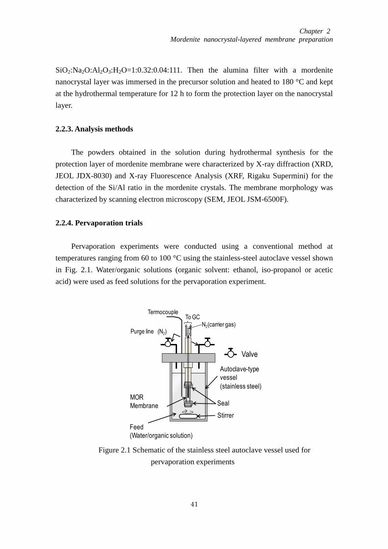
Chapter 2
Mordenite nanocrystal-layered membrane preparation
41
SiO2:Na2O:Al2O3:H2O=1:0.32:0.04:111. Then the alumina filter with a mordenite
nanocrystal layer was immersed in the precursor solution and heated to 180 °C and kept
at the hydrothermal temperature for 12 h to form the protection layer on the nanocrystal
layer.
2.2.3. Analysis methods
The powders obtained in the solution during hydrothermal synthesis for the
protection layer of mordenite membrane were characterized by X-ray diffraction (XRD,
JEOL JDX-8030) and X-ray Fluorescence Analysis (XRF, Rigaku Supermini) for the
detection of the Si/Al ratio in the mordenite crystals. The membrane morphology was
characterized by scanning electron microscopy (SEM, JEOL JSM-6500F).
2.2.4. Pervaporation trials
Pervaporation experiments were conducted using a conventional method at
temperatures ranging from 60 to 100 °C using the stainless-steel autoclave vessel shown
in Fig. 2.1. Water/organic solutions (organic solvent: ethanol, iso-propanol or acetic
acid) were used as feed solutions for the pervaporation experiment.
Figure 2.1 Schematic of the stainless steel autoclave vessel used for
pervaporation experiments
N2(carrier gas)
Feed
(Water/organic solution)
MOR
Membrane
Termocouple
Autoclave-type
vessel
(stainless steel)
Purge line (N2)
Valve
Seal
To GC
Stirrer
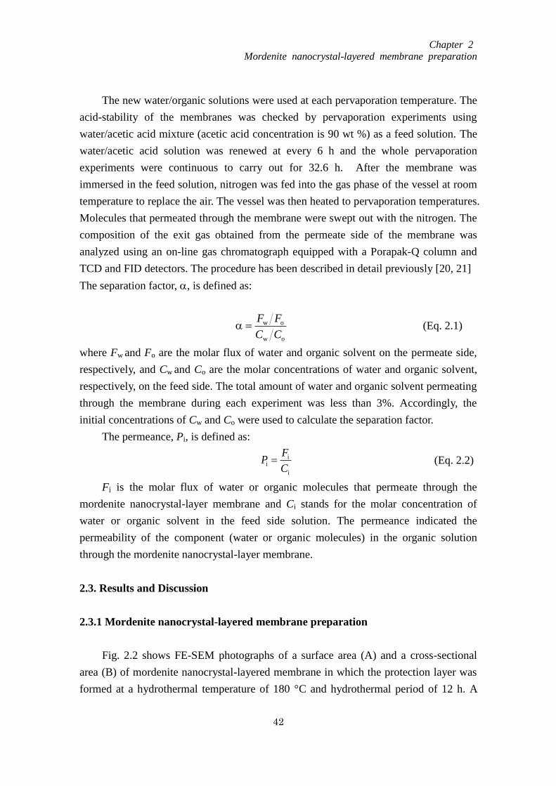
Chapter 2
Mordenite nanocrystal-layered membrane preparation
42
The new water/organic solutions were used at each pervaporation temperature. The
acid-stability of the membranes was checked by pervaporation experiments using
water/acetic acid mixture (acetic acid concentration is 90 wt %) as a feed solution. The
water/acetic acid solution was renewed at every 6 h and the whole pervaporation
experiments were continuous to carry out for 32.6 h. After the membrane was
immersed in the feed solution, nitrogen was fed into the gas phase of the vessel at room
temperature to replace the air. The vessel was then heated to pervaporation temperatures.
Molecules that permeated through the membrane were swept out with the nitrogen. The
composition of the exit gas obtained from the permeate side of the membrane was
analyzed using an on-line gas chromatograph equipped with a Porapak-Q column and
TCD and FID detectors. The procedure has been described in detail previously [20, 21]
The separation factor, , is defined as:
ow
ow
CC
FF (Eq. 2.1)
where Fw and Fo are the molar flux of water and organic solvent on the permeate side,
respectively, and Cw and Co are the molar concentrations of water and organic solvent,
respectively, on the feed side. The total amount of water and organic solvent permeating
through the membrane during each experiment was less than 3%. Accordingly, the
initial concentrations of Cw and Co were used to calculate the separation factor.
The permeance, Pi, is defined as:
i
ii
C
FP (Eq. 2.2)
Fi is the molar flux of water or organic molecules that permeate through the
mordenite nanocrystal-layer membrane and Ci stands for the molar concentration of
water or organic solvent in the feed side solution. The permeance indicated the
permeability of the component (water or organic molecules) in the organic solution
through the mordenite nanocrystal-layer membrane.
2.3. Results and Discussion
2.3.1 Mordenite nanocrystal-layered membrane preparation
Fig. 2.2 shows FE-SEM photographs of a surface area (A) and a cross-sectional
area (B) of mordenite nanocrystal-layered membrane in which the protection layer was
formed at a hydrothermal temperature of 180 °C and hydrothermal period of 12 h. A
Chapter 2
Mordenite nanocrystal-layered membrane preparation
43
protection layer with micrometer-sized crystals was formed on the nanocrystal layer
with a thickness of about 5μm. The crystal size in the protection layer was much larger
than that in the nanocrystal layer, indicating that secondary growth of mordenite
nanocrystals occurred during formation of the protection layer.
The Fig. 2.2 (c) shows the magnified areas between the nanocrystal layer and the
protection layer of the membrane. From the photograph, the crystals consisted in the
protection layer of the membrane were grew from the nanocrystal consisted in the first
layer and the place between the nanocrystal layer and the protection layer of the
membrane is the most compact area.
In order to prepare the membrane with separation ability, the membrane
preparation conditions such as the thickness of the membranes, the hydrothermal
synthesis time were discussed, respectively.
2.3.2. Performance of mordenite nanocrystal-layered membranes in the
pervaporation experiment
Figure 2.2 FE-SEM photographs of mordenite nanocrystal-layered membranes (A)
top view, (B) cross-sectional area, and (C) magnified view of the indicated area.
Nanocrystal layer
3μm×10,000
A
C
Protection layer
Nanocrystal layer
Alumina filter
A
C
B
Protection layer
Alumina filter
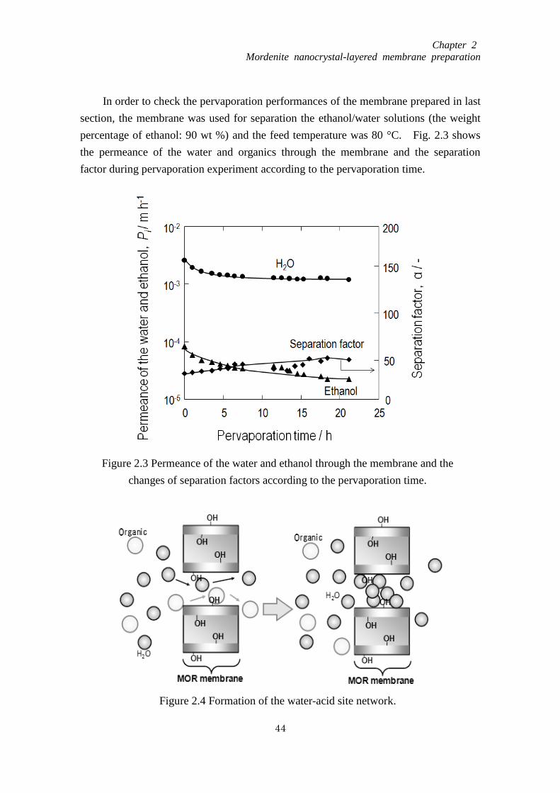
Chapter 2
Mordenite nanocrystal-layered membrane preparation
44
In order to check the pervaporation performances of the membrane prepared in last
section, the membrane was used for separation the ethanol/water solutions (the weight
percentage of ethanol: 90 wt %) and the feed temperature was 80 °C. Fig. 2.3 shows
the permeance of the water and organics through the membrane and the separation
factor during pervaporation experiment according to the pervaporation time.
Figure 2.3 Permeance of the water and ethanol through the membrane and the
changes of separation factors according to the pervaporation time.
Figure 2.4 Formation of the water-acid site network.
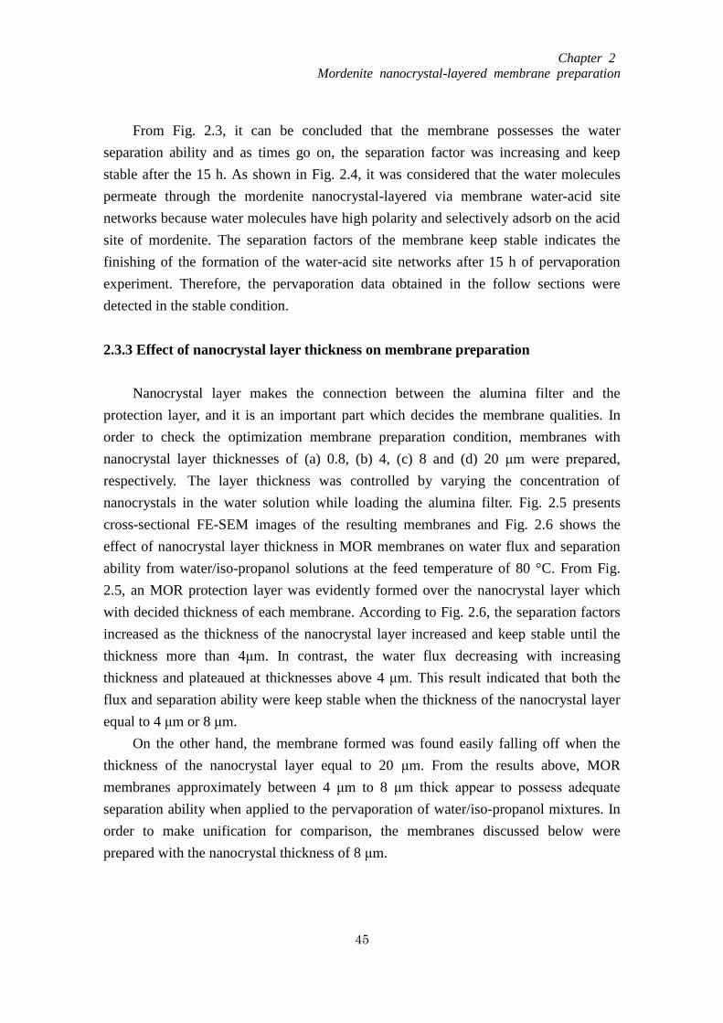
Chapter 2
Mordenite nanocrystal-layered membrane preparation
45
From Fig. 2.3, it can be concluded that the membrane possesses the water
separation ability and as times go on, the separation factor was increasing and keep
stable after the 15 h. As shown in Fig. 2.4, it was considered that the water molecules
permeate through the mordenite nanocrystal-layered via membrane water-acid site
networks because water molecules have high polarity and selectively adsorb on the acid
site of mordenite. The separation factors of the membrane keep stable indicates the
finishing of the formation of the water-acid site networks after 15 h of pervaporation
experiment. Therefore, the pervaporation data obtained in the follow sections were
detected in the stable condition.
2.3.3 Effect of nanocrystal layer thickness on membrane preparation
Nanocrystal layer makes the connection between the alumina filter and the
protection layer, and it is an important part which decides the membrane qualities. In
order to check the optimization membrane preparation condition, membranes with
nanocrystal layer thicknesses of (a) 0.8, (b) 4, (c) 8 and (d) 20 μm were prepared,
respectively. The layer thickness was controlled by varying the concentration of
nanocrystals in the water solution while loading the alumina filter. Fig. 2.5 presents
cross-sectional FE-SEM images of the resulting membranes and Fig. 2.6 shows the
effect of nanocrystal layer thickness in MOR membranes on water flux and separation
ability from water/iso-propanol solutions at the feed temperature of 80 °C. From Fig.
2.5, an MOR protection layer was evidently formed over the nanocrystal layer which
with decided thickness of each membrane. According to Fig. 2.6, the separation factors
increased as the thickness of the nanocrystal layer increased and keep stable until the
thickness more than 4μm. In contrast, the water flux decreasing with increasing
thickness and plateaued at thicknesses above 4 μm. This result indicated that both the
flux and separation ability were keep stable when the thickness of the nanocrystal layer
equal to 4 μm or 8 μm.
On the other hand, the membrane formed was found easily falling off when the
thickness of the nanocrystal layer equal to 20 μm. From the results above, MOR
membranes approximately between 4 μm to 8 μm thick appear to possess adequate
separation ability when applied to the pervaporation of water/iso-propanol mixtures. In
order to make unification for comparison, the membranes discussed below were
prepared with the nanocrystal thickness of 8 μm.
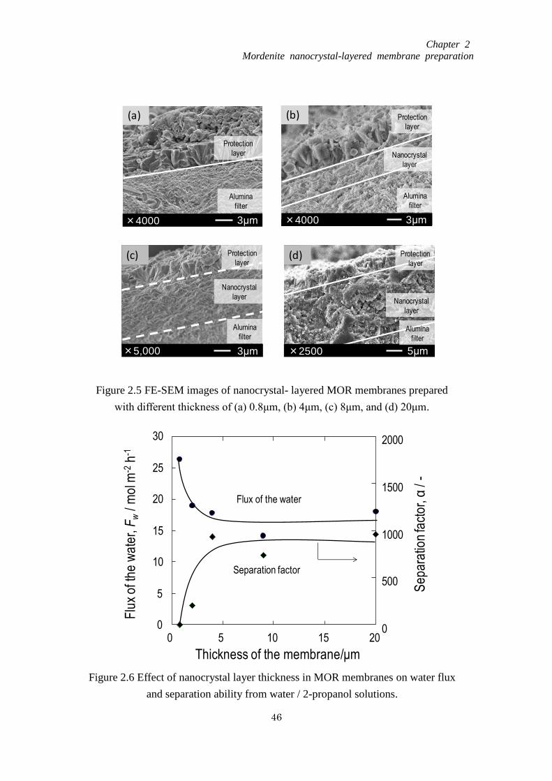
Chapter 2
Mordenite nanocrystal-layered membrane preparation
46
Figure 2.5 FE-SEM images of nanocrystal- layered MOR membranes prepared
with different thickness of (a) 0.8μm, (b) 4μm, (c) 8μm, and (d) 20μm.
3μm×4000
Alumina
filter
Protection
layer
3μm×4000
Protection
layer
Nanocrystal
layer
Alumina
filter
5μm×2500
Alumina
filter
Nanocrystal
layer
Protection
layer
(a) (b)
(d)
3μm×5,000
Protection
layer
Nanocrystal
layer
Alumina
filter
(c)
Figure 2.6 Effect of nanocrystal layer thickness in MOR membranes on water flux
and separation ability from water / 2-propanol solutions.
0
5
10
15
20
25
30
0 5 10 15 20
Thickness of the membrane/μm
Flu
x of
the
wa
ter,
Fw
/ mol
m-2
h-1
0
500
1000
1500
2000
Sep
arat
ion
fact
or, α
/ -
Separation factor
Flux of the water
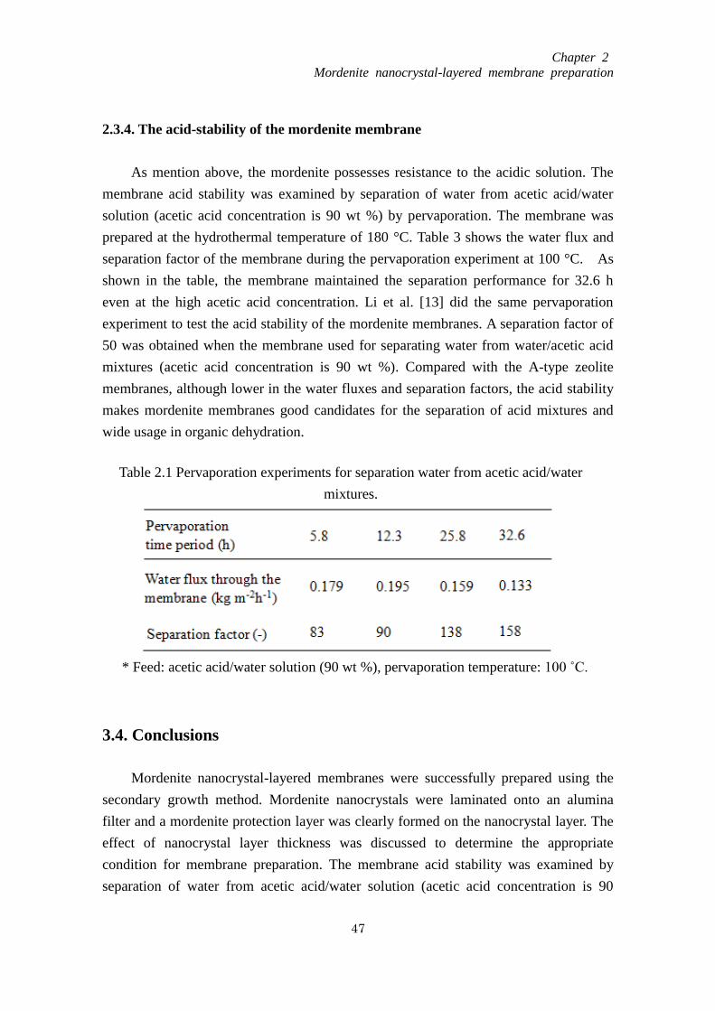
Chapter 2
Mordenite nanocrystal-layered membrane preparation
47
2.3.4. The acid-stability of the mordenite membrane
As mention above, the mordenite possesses resistance to the acidic solution. The
membrane acid stability was examined by separation of water from acetic acid/water
solution (acetic acid concentration is 90 wt %) by pervaporation. The membrane was
prepared at the hydrothermal temperature of 180 °C. Table 3 shows the water flux and
separation factor of the membrane during the pervaporation experiment at 100 °C. As
shown in the table, the membrane maintained the separation performance for 32.6 h
even at the high acetic acid concentration. Li et al. [13] did the same pervaporation
experiment to test the acid stability of the mordenite membranes. A separation factor of
50 was obtained when the membrane used for separating water from water/acetic acid
mixtures (acetic acid concentration is 90 wt %). Compared with the A-type zeolite
membranes, although lower in the water fluxes and separation factors, the acid stability
makes mordenite membranes good candidates for the separation of acid mixtures and
wide usage in organic dehydration.
3.4. Conclusions
Mordenite nanocrystal-layered membranes were successfully prepared using the
secondary growth method. Mordenite nanocrystals were laminated onto an alumina
filter and a mordenite protection layer was clearly formed on the nanocrystal layer. The
effect of nanocrystal layer thickness was discussed to determine the appropriate
condition for membrane preparation. The membrane acid stability was examined by
separation of water from acetic acid/water solution (acetic acid concentration is 90
Table 2.1 Pervaporation experiments for separation water from acetic acid/water
mixtures.
* Feed: acetic acid/water solution (90 wt %), pervaporation temperature: 100 ˚C.
Chapter 2
Mordenite nanocrystal-layered membrane preparation
48
wt %) by pervaporation.
References
[1] S. Funai, T. Tago, T. Masuda, Catal. Today 164 (2011) 443
[2] R.W. Baker, Membrane Technology and Applications, Chapter 9 Pervaporation,
McGraw-Hill, 2000
[3] F. Mizukami, Study in Surface Science and Catalysis 125 (1999) 1
[4] H. Kita, K. Horii, Y. Ohtoshi, K. Tanaka, K. Okamoto, J. Mater. Sci. Lett. 14 (1995)
206
[5] M. Kondo, M. Komori, H. Kita, K. Okamoto, J. Membr. Sci. 133 (1997) 133
[6] K. Okamoto, H. Kita, K. Horii, K. Tanaka, M. Kondo, Ind. & Eng. Chem. Res. 40
(2001) 163
[7] T. Sano, M. Hasegawa, Y. Kawakami, H. Yanagishita, J. Membr. Sci. 107 (1995) 193
[8] G. Li, E. Kikuchi, M. Matsukata, Micropor. Mesopor. Mater. 62 (2003) 211
[9] M. Noack, P. Kolsch, J. Caro, M. Schneider, P. Toussaint, I. Sieber, Micropor.
Mesopor. Mater. 35 (2000) 253
[10] T. Sano, H. Yanagishita, Y. Kiyozumi, F. Mizukami, K. Haraya, J. Membr. Sci. 95
(1994) 221
[11] T. Masuda, S. Otani, T. Tsuji, M. Kitamura, S.R. Mukai, Sep. Purif. Technol. 32
(2003) 181
[12] X. Lin, E. Kikuchi, M. Matsukata, Chem. Comm. 11 (2000) 957
[13] G. Li, E. Kikuchi, M. Matsukata, Sep. Purif. Technol. 32 (2003) 199
[14] A. Navajas, R. Mallada, C. Téllez, J. Coronas, M. Menéndez, J. Santamaría, J.
Membr. Sci.270 (2006) 32
[15] Y. Cui, H. Kita, K. Okamoto, J. Membr. Sci. 236 (2004) 17
[16] T. Nagase, Y. Kiyozumi, Y. Hasegawa, T. Inoue, T. Ikeda, F. Mizukami, Chem. Lett.
36 (2007) 594
[17] Y. Kiyozumi, Y. Nemoto, T. Nishide, T. Nagase, Y. Hasegawa, F. Mizukami,
Micropor. Mesopor. Mater. 116 (2008) 485
[18] J. Čejka, J. van Bekkum, A. Corma, F. Schuth, Characterization and Application,
Elsevier, 2007
[19] K. Sato, K. Sugimoto, T. Kyotani, N. Shimotsuma, T. Kurata, J. Membr. Sci. 385
(2011) 20
[20] T. Tago, Y. Nakasaka, A. Kayoda, T. Masuda, Sep. Purif. Technol. 58 (2007) 7
Chapter 2
Mordenite nanocrystal-layered membrane preparation
49
[21] T. Tago, Y. Nakasaka, A. Kayoda, T. Masuda, Micropor. Mesopor. Mater. 115
(2008) 176
[22] T. Tago, D. Aoki, K. Iwakai, T. Masuda, Topics in Catal. 52 (2009) 865

Chapter 3
Optimization of Mordenite Nanocrystal-layerer
Membrane for Dehydration by Pervaporation
50
Chapter 3
Optimization of Mordenite Nanocrystal-layered Membrane for
Dehydration by Pervaporation
3.1. Introduction
Compared with polymer membrane, there are lots of merits of zeolite membrane
such as the stability in the high temperature and acid solution.
There are various methods to improve the performance of zeolite membranes such
as use the new method for membrane preparation, the use of the new supports [1],
improving the synthesis condition for membrane formation [2], decrease the thickness
of the membrane [3], the control of the size or orientation of the crystals of the
membranes.
A pre-aging treatment, which is defined as the mixing of reagents before onset of
heating to crystallization temperature, can control the morphology and size of the
zeolite crystals [4]. Chen et al. [5] reported morphology control of the zeolite crystal by
a pre-aging treatment during preparation of a silicalite membrane.
The Mordenite nanocrystal-layered membranes consisting of a mordenite
nanocrystal layer and protection layer were successfully prepared in last section. The
main objective of the present study was to discuss the separation mechanism of the
zeolite membrane and improve the performance of the zeolite membrane such as
membrane permeability and separation ability. It is considered the pre-aging
temperature of the mother liquid and the heating rate for formation of the protection
layer affected the secondary growth process that formed the protection layer, leading to
different morphologies and sizes of the crystals in the protection layer. Water flux
increased with decreasing crystal size in the protection layer because the number of
non-zeolitic pores among the mordenite crystal increased as the crystal size decreased.
3.2. Experimental
3.2.1. Preparation of mordenite nanocrystal-layered membranes
Chapter 3
Optimization of Mordenite Nanocrystal-layerer
Membrane for Dehydration by Pervaporation
51
Mordenite nanocrystals (Si/Al=12.5) approximately 120 nm in size were prepared
by the same method refer in chapter 2 (2.2.1. Nanometer size Mordenite crystal
synthesis).
A cylindrical alumina ceramic filter (NGK insulators, LTD.) was used as a
membrane support. The inner and outer diameters and the length of the filter were 6 mm,
11 mm, and 50 mm, respectively. This filter was constructed in two porous regions; the
pore diameter of the inner region was about 2-3 μm (rough region), and the outer region
was dense and its pore diameter was 0.1μm. The filter was immersed in a 0.1 N
hydrochloride solution for 6 h, and washed in distilled water. The mordenite
nanocrystals were dispersed ultrasonically in an alkaline (approximately pH 12)
aqueous solution at a concentration of 5.8 g·m-3
. The dispersed nanocrystals were
layered on the outer surface of cylindrical alumina ceramic filters using a filtration
method under low-pressure vacuum on the permeate side. The thickness of the
nanocrystal layer is about 8μm. To protect the nanocrystal layer against mechanical
shock, a protection layer with micrometer-sized mordenite was formed hydrothermally
(secondary growth) on the nanocrystal layer without organic structure directing agents
(OSDA). An aqueous solution (mother liquid) containing Si and Al sources prepared by
of tetraethylorthosilicate and aluminum isopropoxide was used to form the protection
layer and the molar composition was: SiO2:Na2O:Al2O3:H2O=1:0.32:0.04:111. The
aqueous solution was stirred at room temperature, 60 °C and 80 °C for 24 h, as
pre-aging treatment. Then the alumina filter with a mordenite nanocrystal layer was
immersed in the precursor solution and heated to 150-200 °C with heating rate of
4.2-8.3 °C/h and kept at the hydrothermal temperature for 0-12 h to form the protection
layer on the nanocrystal layer.
3.2.2. Analysis methods
The powders obtained in the solution during hydrothermal synthesis for the
protection layer of mordenite membrane were characterized by X-ray diffraction (XRD,
JEOL JDX-8030) and X-ray Fluorescence Analysis (XRF, Rigaku Supermini) for the
detection of the Si/Al ratio in the mordenite crystals. The membrane morphology and
composition (Si/Al ratio) were characterized by scanning electron microscopy (SEM,
JEOL JSM-6500F) and energy dispersive X-ray spectroscopy (EDS, JEOL
JSM-6510LA), respectively.
3.2.3. Pervaporation trials
Chapter 3
Optimization of Mordenite Nanocrystal-layerer
Membrane for Dehydration by Pervaporation
52
Pervaporation experiments were conducted using a conventional method at
temperatures ranging from 60 to 100 °C using the stainless-steel autoclave vessel shown
in Fig. 1. Water/organic solutions (organic solvent: ethanol, iso-propanol, acetone, or
acetic acid) were used as feed solutions for the pervaporation experiment.
Concentrations of the water/organic solutions and dielectric constants of organic
solvents used are listed in Table 1. The new water/organic solutions were used at each
pervaporation temperature. After the membrane was immersed in the feed solution,
nitrogen was fed into the gas phase of the vessel at room temperature to replace the air.
The vessel was then heated to pervaporation temperatures. Molecules that permeated
through the membrane were swept out with the nitrogen. The composition of the exit
gas obtained from the permeate side of the membrane was analyzed using an on-line gas
chromatograph equipped with a Porapak-Q column and TCD and FID detectors. The
procedure has been described in detail previously [9, 10].
The separation factor, α, is defined as:
ow
ow
CC
FF (1)
Table 3.1 Apparent activation energy of the water flux through a mordenite
nanocrystal-layered membrane from a water/organic solvent solution and the
dielectric constant of the organic solvents.
*Apparent activation energies of water flux through the membranes from water
(without organic solvent)
** The dielectric constant at 20 ºC
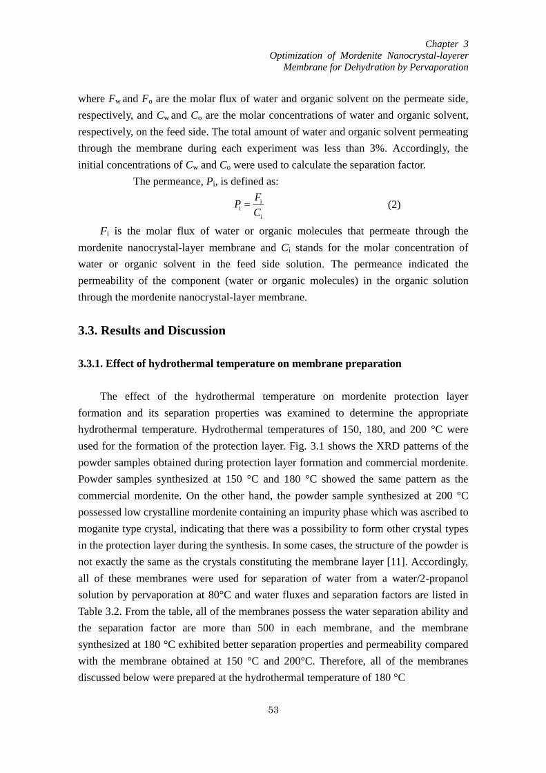
Chapter 3
Optimization of Mordenite Nanocrystal-layerer
Membrane for Dehydration by Pervaporation
53
where Fw and Fo are the molar flux of water and organic solvent on the permeate side,
respectively, and Cw and Co are the molar concentrations of water and organic solvent,
respectively, on the feed side. The total amount of water and organic solvent permeating
through the membrane during each experiment was less than 3%. Accordingly, the
initial concentrations of Cw and Co were used to calculate the separation factor.
The permeance, Pi, is defined as:
i
ii
C
FP (2)
Fi is the molar flux of water or organic molecules that permeate through the
mordenite nanocrystal-layer membrane and Ci stands for the molar concentration of
water or organic solvent in the feed side solution. The permeance indicated the
permeability of the component (water or organic molecules) in the organic solution
through the mordenite nanocrystal-layer membrane.
3.3. Results and Discussion
3.3.1. Effect of hydrothermal temperature on membrane preparation
The effect of the hydrothermal temperature on mordenite protection layer
formation and its separation properties was examined to determine the appropriate
hydrothermal temperature. Hydrothermal temperatures of 150, 180, and 200 °C were
used for the formation of the protection layer. Fig. 3.1 shows the XRD patterns of the
powder samples obtained during protection layer formation and commercial mordenite.
Powder samples synthesized at 150 °C and 180 °C showed the same pattern as the
commercial mordenite. On the other hand, the powder sample synthesized at 200 °C
possessed low crystalline mordenite containing an impurity phase which was ascribed to
moganite type crystal, indicating that there was a possibility to form other crystal types
in the protection layer during the synthesis. In some cases, the structure of the powder is
not exactly the same as the crystals constituting the membrane layer [11]. Accordingly,
all of these membranes were used for separation of water from a water/2-propanol
solution by pervaporation at 80°C and water fluxes and separation factors are listed in
Table 3.2. From the table, all of the membranes possess the water separation ability and
the separation factor are more than 500 in each membrane, and the membrane
synthesized at 180 °C exhibited better separation properties and permeability compared
with the membrane obtained at 150 °C and 200°C. Therefore, all of the membranes
discussed below were prepared at the hydrothermal temperature of 180 °C
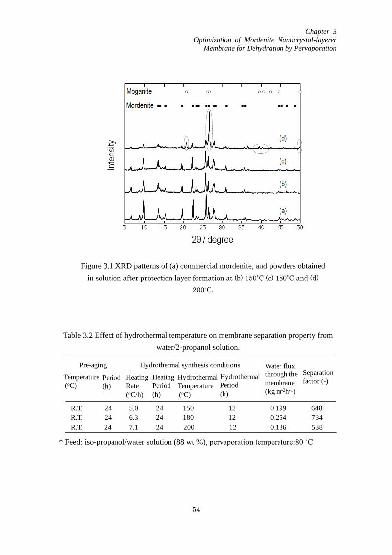
Chapter 3
Optimization of Mordenite Nanocrystal-layerer
Membrane for Dehydration by Pervaporation
54
Figure 3.1 XRD patterns of (a) commercial mordenite, and powders obtained
in solution after protection layer formation at (b) 150˚C (c) 180˚C and (d)
200˚C.
Table 3.2 Effect of hydrothermal temperature on membrane separation property from
water/2-propanol solution.
* Feed: iso-propanol/water solution (88 wt %), pervaporation temperature:80 ˚C
Water flux
through the
membrane
(kg m-2h-1)
Separation
factor (-)Hydrothermal
Temperature
(oC)
150
180
200
0.199 648
0.254
0.186
734
538
Pre-aging
Heating
Rate
(oC/h)
Hydrothermal synthesis conditions
Heating
Period
(h)
Temperature
(oC)Period
(h)
24
24
24
24
24
24
R.T.
R.T.
R.T.
5.0
6.3
7.1
Hydrothermal
Period
(h)
12
12
12
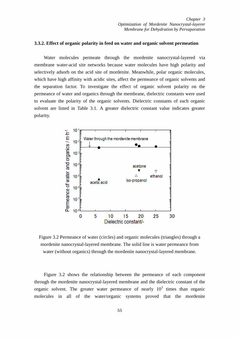
Chapter 3
Optimization of Mordenite Nanocrystal-layerer
Membrane for Dehydration by Pervaporation
55
3.3.2. Effect of organic polarity in feed on water and organic solvent permeation
Water molecules permeate through the mordenite nanocrystal-layered via
membrane water-acid site networks because water molecules have high polarity and
selectively adsorb on the acid site of mordenite. Meanwhile, polar organic molecules,
which have high affinity with acidic sites, affect the permeance of organic solvents and
the separation factor. To investigate the effect of organic solvent polarity on the
permeance of water and organics through the membrane, dielectric constants were used
to evaluate the polarity of the organic solvents. Dielectric constants of each organic
solvent are listed in Table 3.1. A greater dielectric constant value indicates greater
polarity.
Figure 3.2 shows the relationship between the permeance of each component
through the mordenite nanocrystal-layered membrane and the dielectric constant of the
organic solvent. The greater water permeance of nearly 103 times than organic
molecules in all of the water/organic systems proved that the mordenite
Figure 3.2 Permeance of water (circles) and organic molecules (triangles) through a
mordenite nanocrystal-layered membrane. The solid line is water permeance from
water (without organics) through the mordenite nanocrystal-layered membrane.
Chapter 3
Optimization of Mordenite Nanocrystal-layerer
Membrane for Dehydration by Pervaporation
56
nanocrystal-layered membrane possess high water separation ability from the mixtures.
Since the high Al element existed in mordenite zeolite structure generated high
hydrophilicity, water molecules have higher affinity to the mordenite surface compared
with organic molecules. Moreover, water permeance from a water/organic solution
through a membrane was identical regardless of the organic solvent in the feed, and
exhibited nearly the same value as the permeance of water through a membrane from a
pure water solution (i.e., without organic solvent), indicating that the dominant
mechanism of the permeation of water is the same regardless of coexisting organic
molecules.
Table 3.1 shows the apparent activation energies of water flux through the
membranes from the water/organic solutions. The apparent activation energies of water
flux through the membranes from pure water (without an organic solvent) are also
showed for comparison. The apparent activation energies of water flux through the
mordenite nanocrystal-layered membrane were similar regardless of the organic solvent
in the feed and were close to the apparent activation energy of water flux through the
membrane from a pure water feed. The apparent activation energy of water flux through
the hydrophilic silicalite-1 nanocrystal-layered membrane from water/acetone solution
(acetone concentration is 90 wt %) [9, 10] was 35 kJ/mol and the value was similar to
that of the mordenite nanocrystal-layered membrane. In the hydrophilic silicalite-1
nanocrystal-layered membrane, water-silanol networks that formed on non-zeolitic pore
spaces among the crystals acted as the main channel for water permeation, and the
interface between the nanocrystal layer and protection layer was important for the
separation because this area became the densest area in the membrane [10]. Since the
mordenite membrane was prepared by the same procedure as the silicalite-1 membrane
[10], it was considered that there were some non-zeolitic pores among the crystals.
During the pervaporation to separate water from water/organic mixtures, water
molecules were adsorbed on the surfaces of zeolitic and non-zeolitic pores. As
compared with silanol groups on the surface of silicalite-1 crystal, the affinity of water
molecules to the surface of mordenite crystal was much higher due to the strong ionic
sites. However, since the mordenite membrane showed almost the same activation
energy as the slilicalite-1 membrane, the non-zeolitic pores among the crystals, on
which the water adsorption layer was formed, were the important channel for water
permeation. The water molecules can diffuse through the non-zeolitic pore surrounded
by the water adsorption layer, and consequently the size of non-zeolitic pores mainly
affects the separation properties.

Chapter 3
Optimization of Mordenite Nanocrystal-layerer
Membrane for Dehydration by Pervaporation
57
3.3.3 Effects of pre-aging and heating rate for synthesis of the protection layer on
performance of mordenite nanocrystal-layered membranes
Ideally, the zeolite membranes must be continuous with good cross-linking
between crystals and free of pinholes and cracks to get high selectivities. However, most
of the synthesis procedures render membranes with some intercrystalline gaps and
defects [12, 13]. The amount of these crystals and their sizes play an important role in
the overall quality of the membranes [14]. It is suggested that the non-zeolitic pores
have size distributions and the pores smaller than the zeolite pores may also affect flux
and selectivity [15]. Moreover, some studies showed that the non-zeolitic pores are
selective for some mixtures and pervaporation separations even positively affected by
non-zeolitic pores [16].
In order to investigate the effect of the non-zeolitic pores on membranes quality,
mordenite nanocrystal-layered membranes at conditions of hydrothermal period of 0, 12
and 24 h were prepared. Table 3.3 shows the results of membrane performance of water
flux and separation factor as a function of hydrothermal period. In the case of M1,
though prepared without hydrothermal period, the membrane exhibited the separation
ability. Moreover, the separation factor of membranes (M1, M2, and M3) increased with
increasing the hydrothermal period, implying that non-zeolitic pores were exist among
the crystals and that the size of the non-zeolitic pore decreased to the appropriate size
for water separation. On the other hand, the long hydrothermal period led to the
excessive secondary growth of zeolite, thereby resulting in the decrease in water flux.
Such an appropriate pore space was expected to be formed around the interface between
the nanocrystal and protection layers [10].
The morphology and crystal size around the interface formed by hydrothermal
synthesis are the important factors affecting the membrane permeability and separation
ability. There are two parameters by which to modify the crystal growth during the
secondary growth; the pre-aging treatment of the mother liquid and the heating rate to
the hydrothermal temperature. To achieve high flux of water and high separation ability,
the effects of pre-aging temperature and the heating rate on the crystal morphology and
membrane performance were examined. The pre-aging temperatures of room
temperature, 60 °C, and 80 °C with a pre-aging time of 24 h were tested for protection
layer formation. After the autoclave temperature reached 180 °C, hydrothermal
treatment to form the protection layer (secondary growth) was stopped. Table 3.3 shows
the experimental conditions used for protection layer formation and the separation
properties of the membranes using a water/iso-propanol solution. Compared with
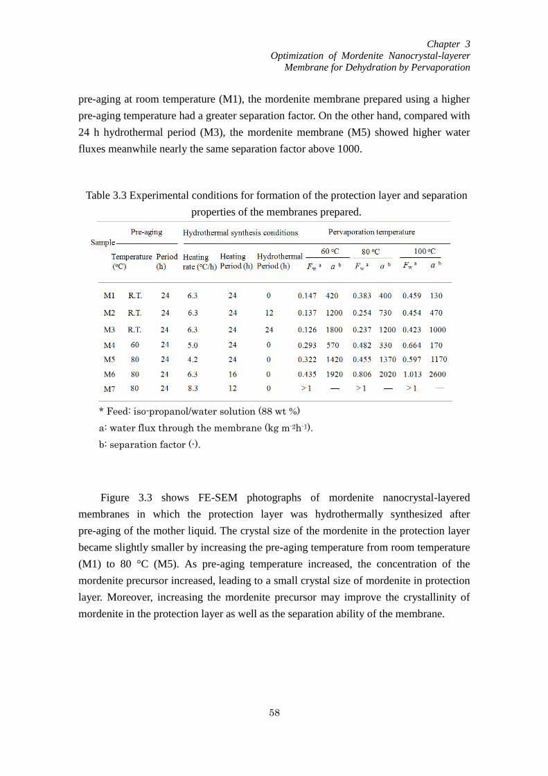
Chapter 3
Optimization of Mordenite Nanocrystal-layerer
Membrane for Dehydration by Pervaporation
58
pre-aging at room temperature (M1), the mordenite membrane prepared using a higher
pre-aging temperature had a greater separation factor. On the other hand, compared with
24 h hydrothermal period (M3), the mordenite membrane (M5) showed higher water
fluxes meanwhile nearly the same separation factor above 1000.
Figure 3.3 shows FE-SEM photographs of mordenite nanocrystal-layered
membranes in which the protection layer was hydrothermally synthesized after
pre-aging of the mother liquid. The crystal size of the mordenite in the protection layer
became slightly smaller by increasing the pre-aging temperature from room temperature
(M1) to 80 °C (M5). As pre-aging temperature increased, the concentration of the
mordenite precursor increased, leading to a small crystal size of mordenite in protection
layer. Moreover, increasing the mordenite precursor may improve the crystallinity of
mordenite in the protection layer as well as the separation ability of the membrane.
Table 3.3 Experimental conditions for formation of the protection layer and separation
properties of the membranes prepared.
* Feed: iso-propanol/water solution (88 wt %)
a: water flux through the membrane (kg m-2h-1).
b: separation factor (-).
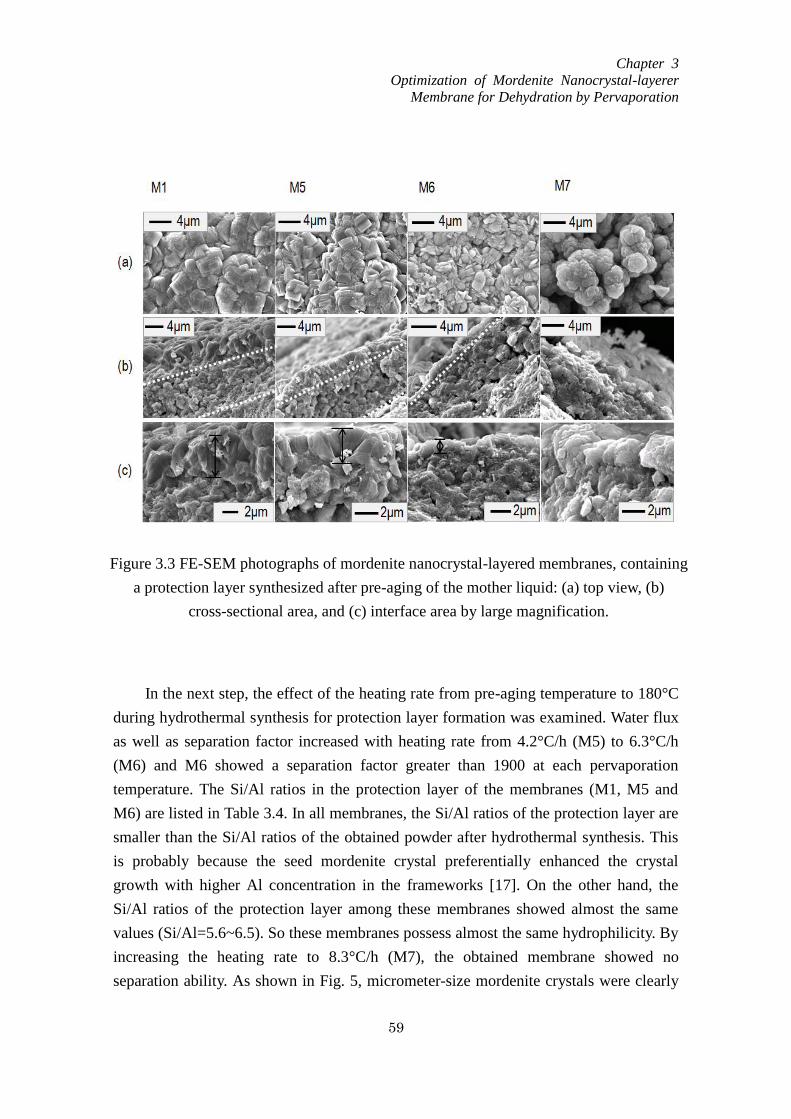
Chapter 3
Optimization of Mordenite Nanocrystal-layerer
Membrane for Dehydration by Pervaporation
59
In the next step, the effect of the heating rate from pre-aging temperature to 180°C
during hydrothermal synthesis for protection layer formation was examined. Water flux
as well as separation factor increased with heating rate from 4.2°C/h (M5) to 6.3°C/h
(M6) and M6 showed a separation factor greater than 1900 at each pervaporation
temperature. The Si/Al ratios in the protection layer of the membranes (M1, M5 and
M6) are listed in Table 3.4. In all membranes, the Si/Al ratios of the protection layer are
smaller than the Si/Al ratios of the obtained powder after hydrothermal synthesis. This
is probably because the seed mordenite crystal preferentially enhanced the crystal
growth with higher Al concentration in the frameworks [17]. On the other hand, the
Si/Al ratios of the protection layer among these membranes showed almost the same
values (Si/Al=5.6~6.5). So these membranes possess almost the same hydrophilicity. By
increasing the heating rate to 8.3°C/h (M7), the obtained membrane showed no
separation ability. As shown in Fig. 5, micrometer-size mordenite crystals were clearly
Figure 3.3 FE-SEM photographs of mordenite nanocrystal-layered membranes, containing
a protection layer synthesized after pre-aging of the mother liquid: (a) top view, (b)
cross-sectional area, and (c) interface area by large magnification.
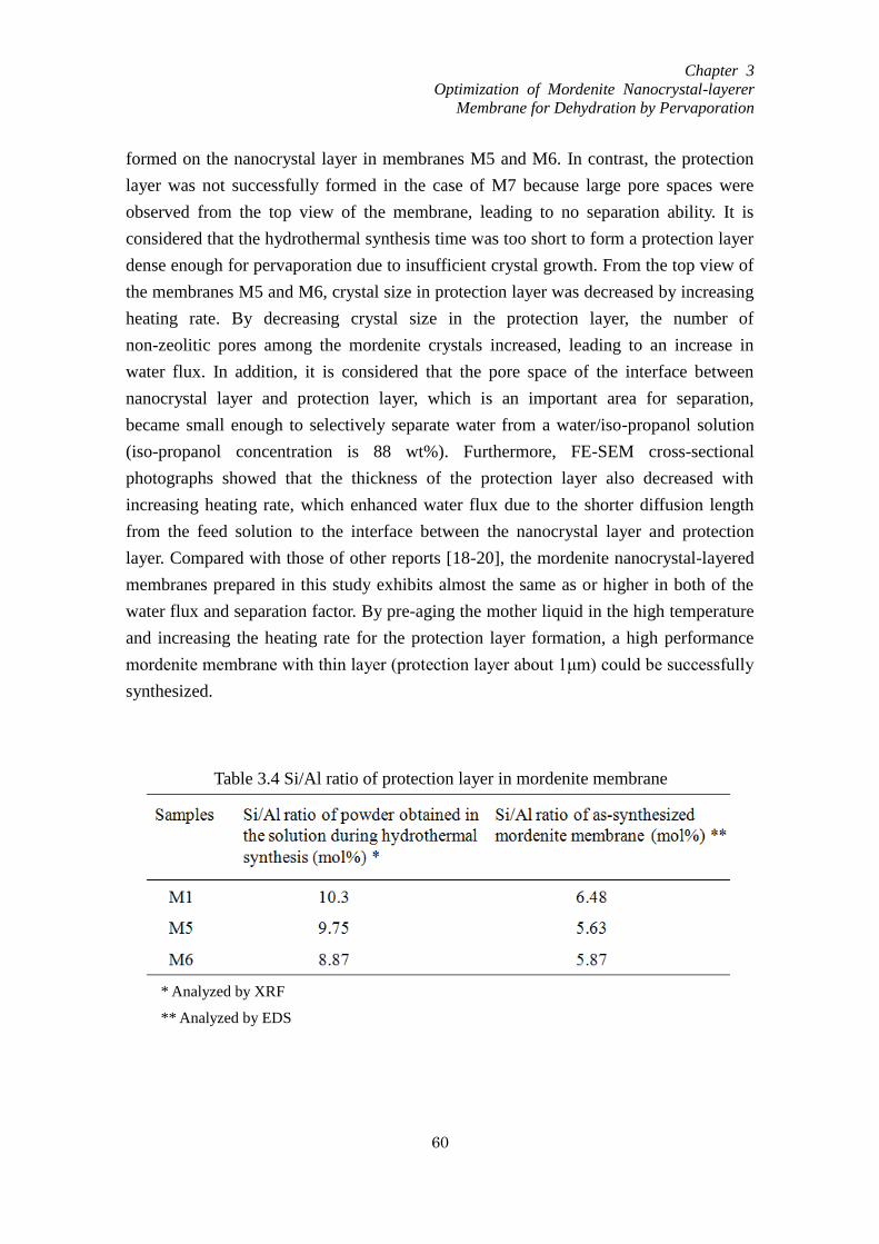
Chapter 3
Optimization of Mordenite Nanocrystal-layerer
Membrane for Dehydration by Pervaporation
60
formed on the nanocrystal layer in membranes M5 and M6. In contrast, the protection
layer was not successfully formed in the case of M7 because large pore spaces were
observed from the top view of the membrane, leading to no separation ability. It is
considered that the hydrothermal synthesis time was too short to form a protection layer
dense enough for pervaporation due to insufficient crystal growth. From the top view of
the membranes M5 and M6, crystal size in protection layer was decreased by increasing
heating rate. By decreasing crystal size in the protection layer, the number of
non-zeolitic pores among the mordenite crystals increased, leading to an increase in
water flux. In addition, it is considered that the pore space of the interface between
nanocrystal layer and protection layer, which is an important area for separation,
became small enough to selectively separate water from a water/iso-propanol solution
(iso-propanol concentration is 88 wt%). Furthermore, FE-SEM cross-sectional
photographs showed that the thickness of the protection layer also decreased with
increasing heating rate, which enhanced water flux due to the shorter diffusion length
from the feed solution to the interface between the nanocrystal layer and protection
layer. Compared with those of other reports [18-20], the mordenite nanocrystal-layered
membranes prepared in this study exhibits almost the same as or higher in both of the
water flux and separation factor. By pre-aging the mother liquid in the high temperature
and increasing the heating rate for the protection layer formation, a high performance
mordenite membrane with thin layer (protection layer about 1μm) could be successfully
synthesized.
Table 3.4 Si/Al ratio of protection layer in mordenite membrane
* Analyzed by XRF
** Analyzed by EDS
Chapter 3
Optimization of Mordenite Nanocrystal-layerer
Membrane for Dehydration by Pervaporation
61
3.4. Conclusions
Mordenite nanocrystal-layered membranes were successfully prepared using the
secondary growth method. Mordenite nanocrystals were laminated onto an alumina
filter and a mordenite protection layer was clearly formed on the nanocrystal layer. Four
types of water/organic solvent solutions were prepared for pervaporation experiments
using the mordenite nanocrystal-layered membranes. Permeance of water through the
mordenite nanocrystal-layered membrane was similar regardless of the polarity of the
organic solvent in the feed solutions however the permeances of the organic molecules
depended on their polarities. The mechanisms of water permeation through the
mordenite nanocrystal-layered membranes can be considered as the adsorbed water
layer formed on both of the zeolitic pores and non-zeolitic pores among crystals for
water permeation. The appropriate pore space was formed around the interface between
the nanocrystal and protection layer which was expected to be the main separation area
of the membranes. Formation of small size mordenite crystals in the protection layer
enhanced the separation ability as well as permeability of the mordenite
nanocrystal-layered membranes.
Chapter 3
Optimization of Mordenite Nanocrystal-layerer
Membrane for Dehydration by Pervaporation
62
References
[1] J.J. Jafar, P.M. Budd, Micropor. Mesopor. Mater. 12 (1997) 305
[2] S. Li, V.A. Tuan, J.L. Falconer, R.D. Noble, Micropor. Mesopor. Mater. 53 (2002) 59
[3] Z.P. Lai, G. Bonilla, I. Diaz, J.G. Nery, K. Sujaoti, M.A. Amat, E. Kokkoli, O.
Terasaki, R.W. Thompson, M.Tsapatsis, D.G. Vlachos, Science 300 (2002) 456
[4]Q. Li, B. Mihailova, D. Creaser, J. Sterte, Micropor. Mesopor, Mater. 43 (2001) 51
[5] H. Chen, C. Song, W, Yang, Micropor. Mesopor, Mater. 102 (2007) 250
[6] M.M. Nia, H. Amiri, J. Chem. Thermodynamics 57 (2013) 68
[7] G. Åkerlöf, J. Amer. Chem. Soc. 54 (11) (1932) 4125
[8] C.G. Malmberg, A.A. Maryott, Journal of Research of the National Bureau of
Standards 56 (1) (1956) 2641
[9] T. Tago, Y. Nakasaka, A. Kayoda, T. Masuda, Sep. Purif. Technol. 58 (2007) 7
[10] T. Tago, Y. Nakasaka, A. Kayoda, T. Masuda, Micropor. Mesopor, Mater. 115
(2008) 176
[11] X. Li, H. Kita, H. Zhu, Z. Zhang, K. Tanaka, J. Membr. Sci. 339 (2009) 224
[12] A.K. Pabby, S.S.H. Rizvi, A.M. Sastre, Handbook of Membrane Separations, 2008,
P289
[13] M. Nomura, T. Yamaguchi, S. Nakao, J. Membr. Sci. 187 (2001) 203
[14] T.C. Bowen, R.D. Noble, J.L. Falconer, J. Membr. Sci. 245 (2004) 15
[15] T.C. Bowen, H. Kalipcilar, J.L. Falconer, R.D. Noble, J. Membr. Sci.215 (2003)
235
[16] K. Okamoto, H. Kita, K. Horii, K. Tanaka, M. Konodo, Ind. Eng.Chem.Res. 40
(2001) 163
[17] M. Noack, P. Kölsch, V. Seefeld, P. Toussaint, G. Georgi, J. Caro, Miropor.
Mesopor. Mater. 79 (2005) 329
[18] Y.F. Zhang, Z.Q. Xu, Q.L. Chen, J.Membr. Sci. 210 (2002) 361
[19] G. Li, E. Kikuchi, M. Matsukata, Micropor. Mesopor. Mater. 62 (2003) 211
[20] X. Lin, E. Kikuchi, M. Matsukata, Chem. Comm.11 (2000) 957
Chapter 4
MTW Nanocrystal-layered Membrane Preparation
63
Chapter 4
MTW nanocrystal-layered membrane preparation
4.1. Introduction
Zeolites are among the most important porous materials used in industrial
operations and have been widely applied as catalysts and adsorbents [1-5]. The use of
zeolite membranes for separations has attracted considerable attention due to the
inherent high thermal and chemical stability of these substances compared with
polymeric materials. To date, membranes made using zeolites with the framework codes
LTA [6, 7], FAU [8, 9], MOR [10, 11], BEA [12,13] and MFI [14, 15] have been studied
and based on the different characteristics such as pore size and hydrophilic/hydrophobic
ability, these different type membranes can be widely used for gas or liquid separation
and zeolite-membrane reactors [16, 17]. In addition, the Mitsui Engineering and
Shipbuilding Co. has demonstrated the separation of aqueous solutions by pervaporation
using zeolite membranes [18].
MTW-type zeolite is a high-silica material with a unidimensional 12-membered
ring channel system [19], in which the Si/Al ratio can be controlled over a wide range of
values. This zeolite has been successfully prepared using conventional hydrothermal
synthesis [20-22], and it has been shown that the crystal size obtained can be varied by
using different organic structure directing agents (OSDAs) due to the resulting
differences in the nucleation and crystallization rates [23, 24]. Applications of MTW
zeolite to structure-sensitive catalytic reactions have been developed recently [25, 26],
but there have been only a few reports concerning the use of MTW zeolite in separation
membranes.
The main objective of the present work was to prepare an MTW nanocrystal layered
membrane and apply it to the selective separation of water from a water/2-propanol
solution by pervaporation. Previously, we succeeded in preparing hydrophilic MFI and
MOR zeolite nanocrystal layered membranes consisting of a zeolite nanocrystal layer
and a protection layer for the removal of water from water/organic solutions [27-29].
The application of nano-sized MTW crystal as a seed crystal was effective in improving
the membrane performance. The water flux of the layer membrane prepared using the
nanocrystals was approximately 100 times high compared with the dense membrane
Chapter 4
MTW Nanocrystal-layered Membrane Preparation
64
prepared by in situ hydrothermal synthesis methods [30]. The protection layer is growth
from the seed layer (nanocrystal layer) during the hydrothermal synthesis. It was found
that the interface between the nanocrystal and protection layer is the densest area in the
membrane which was considered to be the main separation region of the membrane
[27-29]. The zeolite nanocrystal in this study, the same preparation method reported
previously was applied to make the MTW zeolite membrane.
4.2. Experimental
4.2.1. Preparation of MTW zeolite powders
MTW nanocrystals approximately 50 nm in size were obtained via hydrothermal
synthesis with tetraethylammonium bromide (TEABr, Wako Chemicals) as the OSDA.
An aqueous solution containing sodium aluminate (Wako Chemicals), TEABr and
sodium hydroxide (Wako Chemicals) was prepared and stirred at room temperature for
3 h. Subsequently, LUDOX HS-40 colloidal silica (Si source, Aldrich Chemicals) was
added followed by further stirring at room temperature for 3 h to ensure a
homogeneous mixture. The composition ratio of the resulting mixture was
20Na2O:120TEABr:200SiO2:xAl2O3:11110H2O, where x = 1 to 2. The mixture was
transferred to a Teflon-sealed stainless steel bottle and this container was heated to
150 °C and held at this temperature for 6 days with stirring. The product was washed
thoroughly three times each with deionized water and 2-propanol and then dried
overnight at 110 °C. The OSDA was removed by calcination in air at 550
°C for 12 h.
The morphology, composition (Si/Al ratio) and crystallinity of the resulting zeolite were
assessed by field emission scanning electron microscopy (FE-SEM; JEOL JSM-6500F),
energy dispersive X-ray spectroscopy (EDS, JEOL JSM-6510LA) and X-ray diffraction
(XRD; JEOL JDX-8020), respectively. The porous and Brunauer-Emmett-Teller (BET)
surface areas of the zeolite were determined from N2 adsorption isotherms
(BELSORP-mini).
4.2.2. Preparation of MTW nanocrystal-layered membranes
The MTW nanocrystals were subsequently ultrasonically dispersed in a sodium
hydroxide aqueous solution (approximately pH 12) at concentrations of 3.5 to 6.5 g·m-3
.
The dispersed nanocrystals were layered on the outer surfaces of cylindrical alumina
ceramic filters (NGK insulators) via a filtration method driven by the application of a
Chapter 4
MTW Nanocrystal-layered Membrane Preparation
65
vacuum to the permeate side. The inner and outer diameters and the length of the filters
were 6, 11 and 50 mm, respectively. Each filter consisted of two porous regions; an
inner region with a pore diameter of approximately 2-3 μm (the rough region) and a
dense outer region with a pore diameter of 0.1 μm. Each filter was immersed in 0.1 M
HCl for 6 h and then washed in distilled water prior to preparation of the membranes.
The thickness of the MTW nanocrystal layer on the ceramic filter could be controlled by
changing the concentration of nanocrystals in the sodium hydroxide aqueous solution.
Finally, to protect the nanocrystal layer against mechanical shock, a protection layer was
hydrothermally formed on the nanocrystal layer using either TEABr or
methyltriethylammonium chloride (MTEACl, Tokyo Chemical Industry) as the OSDA.
The composition of the synthesis mixture when using TEABr as the OSDA was
20Na2O:100TEABr:500SiO2:xAl2O3:11110H2O, where x = 1.25 to 5, while the
composition with MTEACl was 20Na2O:60TEABr:300SiO2:5Al2O3:11110H2O. The
aqueous solution containing the MTW nanocrystal-layered membrane was heated to
150 °C for 6 days to form a protection layer on the nanocrystal layer. The zeolite
membrane thus prepared was washed with distilled water and then dried in air.
4.2.3. Pervaporation trials
Pervaporation trials were carried out using a conventional method at temperatures
ranging from 60 to 100 °C in a stainless steel autoclave shown in Fig. 4.1, with
water/2-propanol (2-propanol concentration is 88 wt %) as the feed solution. The
acid-stability of the membranes was checked by pervaporation experiments using
water/acetic acid mixture (acetic acid concentration is 90 wt %) as a feed solution. The
water/acetic acid solution was renewed at every 6 h and the whole pervaporation
experiments were continuous to carry out for 18 h. After the membrane was immersed
in this solution, the air in the autoclave was replaced with room temperature nitrogen
and the vessel was heated to the desired pervaporation temperature. Molecules
permeating through the membrane were swept out with a flow of nitrogen that was
continuously fed to the permeate side of the membrane. The composition of the exit gas
from the permeate side was analyzed using an on-line gas chromatograph equipped with
a molecular sieve 5Å column and TCD and FID detectors.

Chapter 4
MTW Nanocrystal-layered Membrane Preparation
66
The separation factor, , was defined as
where Fw and Fi are the molar flux of water and 2-propanol on the permeate side,
respectively, and Cw and Ci are the molar concentrations of water and 2-propanol on the
feed side, respectively.
The membrane separation ability and water flux are tested to become stable after
the pervaporation test carried out for 5 h in the same temperature. Therefore, all of the
pervaporation data were detected in the membrane stable condition (after 5 h
pervaporation experiment in the same temperature). The duration of the every test was 8
h and after each pervaporation test, the membranes were at first washed with water and
then dry in air for 12 h. The total amount of water and organic solvent permeating
through the membrane during each experiment was less than 3 wt%. Accordingly, the
initial concentrations were used to calculate the separation factor.
iw
iw
CC
FF
Figure 4.1 Schematic of the stainless steel autoclave vessel used
for pervaporation experiments
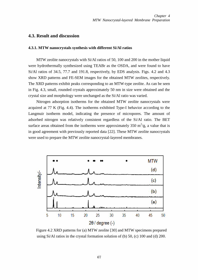
Chapter 4
MTW Nanocrystal-layered Membrane Preparation
67
4.3. Result and discussion
4.3.1. MTW nanocrystals synthesis with different Si/Al ratios
MTW zeolite nanocrystals with Si/Al ratios of 50, 100 and 200 in the mother liquid
were hydrothermally synthesized using TEABr as the OSDA, and were found to have
Si/Al ratios of 34.5, 77.7 and 191.8, respectively, by EDS analysis. Figs. 4.2 and 4.3
show XRD patterns and FE-SEM images for the obtained MTW zeolites, respectively.
The XRD patterns exhibit peaks corresponding to an MTW-type zeolite. As can be seen
in Fig. 4.3, small, rounded crystals approximately 50 nm in size were obtained and the
crystal size and morphology were unchanged as the Si/Al ratio was varied.
Nitrogen adsorption isotherms for the obtained MTW zeolite nanocrystals were
acquired at 77 K (Fig. 4.4). The isotherms exhibited Type-I behavior according to the
Langmuir isotherm model, indicating the presence of micropores. The amount of
adsorbed nitrogen was relatively consistent regardless of the Si/Al ratio. The BET
surface areas obtained from the isotherms were approximately 350 m2/g, a value that is
in good agreement with previously reported data [22]. These MTW zeolite nanocrystals
were used to prepare the MTW zeolite nanocrystal-layered membranes.
Figure 4.2 XRD patterns for (a) MTW zeolite [30] and MTW specimens prepared
using Si/Al ratios in the crystal formation solution of (b) 50, (c) 100 and (d) 200.
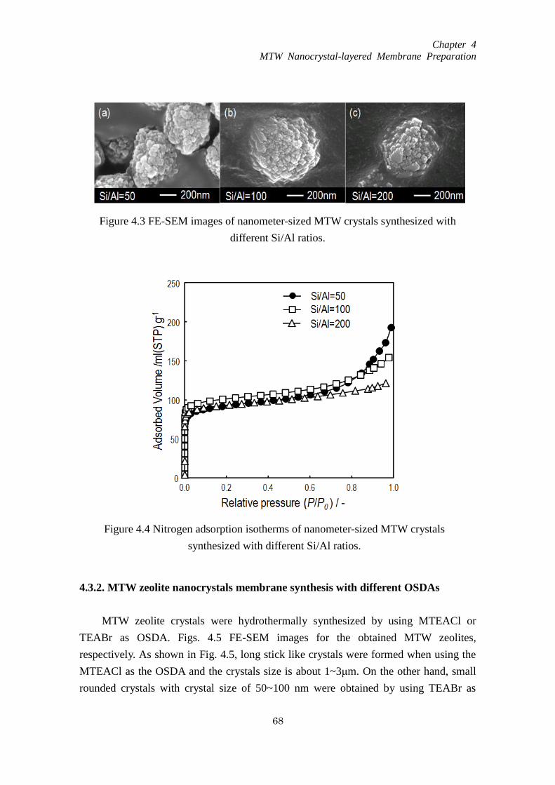
Chapter 4
MTW Nanocrystal-layered Membrane Preparation
68
4.3.2. MTW zeolite nanocrystals membrane synthesis with different OSDAs
MTW zeolite crystals were hydrothermally synthesized by using MTEACl or
TEABr as OSDA. Figs. 4.5 FE-SEM images for the obtained MTW zeolites,
respectively. As shown in Fig. 4.5, long stick like crystals were formed when using the
MTEACl as the OSDA and the crystals size is about 1~3μm. On the other hand, small
rounded crystals with crystal size of 50~100 nm were obtained by using TEABr as
Figure 4.4 Nitrogen adsorption isotherms of nanometer-sized MTW crystals
synthesized with different Si/Al ratios.
Figure 4.3 FE-SEM images of nanometer-sized MTW crystals synthesized with
different Si/Al ratios.

Chapter 4
MTW Nanocrystal-layered Membrane Preparation
69
OSDA.
After the MTW-type zeolite nanocrystals (Si/Al ratio= 34.5) were piled up on the
aluminum ceramic filters, protection layers were hydrothermally formed on the MTW
nanocrystal layer using different OSDAs, respectively (MTEACl and TEABr). The
Si/Al ratio in the mother liquid used to prepare protection layer of both membrane
samples for these trials was 50. Fig. 4.6 presents SEM photographs of cross-sections
((a) and (b)) and an overhead view (c) of the resulting membranes. An MTW
nanocrystal layer with a thickness of approximately 17 µm can be clearly observed on
the filter in each membrane and it is evident that a protection layer was formed on the
nanocrystal layer. Differences in the crystal morphology of the protection layers are
also clear. In the membrane prepared using MTEACl as the OSDA, the protection layer
is composed of micrometer-sized column-shaped crystals (approximately 2 μm in size),
and the Si/Al ratio in these crystals was found to be 49.1 by EDS. In contrast, the use of
TEABr as the OSDA formed aggregated MTW nanocrystals with a Si/Al ratio of 43.5
as the protection layer. These variations in the crystal morphology of the protection
layer are ascribed to the difference in the secondary growth rate of the MTW zeolite
depending on the type of OSDA [23, 24].
Figure 4.5 FE-SEM images of MTW crystals synthesized with different OSDAs.
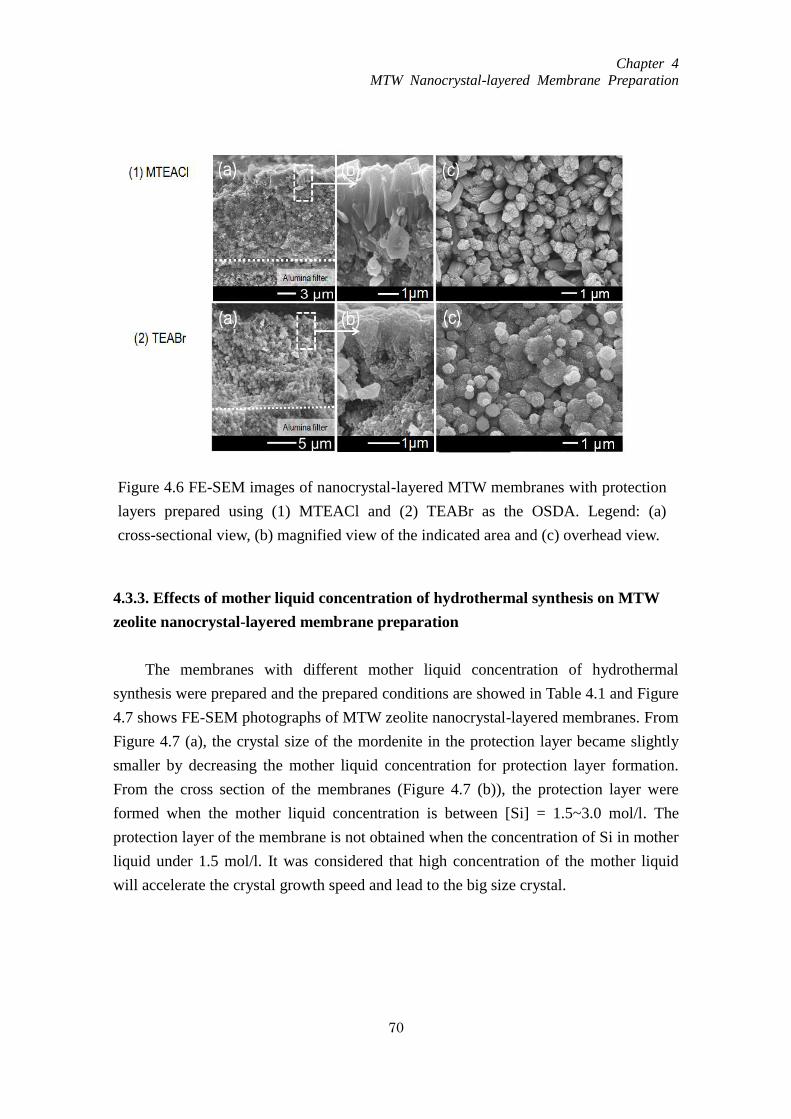
Chapter 4
MTW Nanocrystal-layered Membrane Preparation
70
4.3.3. Effects of mother liquid concentration of hydrothermal synthesis on MTW
zeolite nanocrystal-layered membrane preparation
The membranes with different mother liquid concentration of hydrothermal
synthesis were prepared and the prepared conditions are showed in Table 4.1 and Figure
4.7 shows FE-SEM photographs of MTW zeolite nanocrystal-layered membranes. From
Figure 4.7 (a), the crystal size of the mordenite in the protection layer became slightly
smaller by decreasing the mother liquid concentration for protection layer formation.
From the cross section of the membranes (Figure 4.7 (b)), the protection layer were
formed when the mother liquid concentration is between [Si] = 1.5~3.0 mol/l. The
protection layer of the membrane is not obtained when the concentration of Si in mother
liquid under 1.5 mol/l. It was considered that high concentration of the mother liquid
will accelerate the crystal growth speed and lead to the big size crystal.
Figure 4.6 FE-SEM images of nanocrystal-layered MTW membranes with protection
layers prepared using (1) MTEACl and (2) TEABr as the OSDA. Legend: (a)
cross-sectional view, (b) magnified view of the indicated area and (c) overhead view.

Chapter 4
MTW Nanocrystal-layered Membrane Preparation
71
Table 4.1 Composition of the mother liquid for MTW membrane protection
layer formation
(a)
(b)
Figure 4.7 FE-SEM images of nanocrystal-layered MTW membranes with
protection layers formation by using different mother liquid concentration. (a)
Overhead view (b) cross-sectional view.
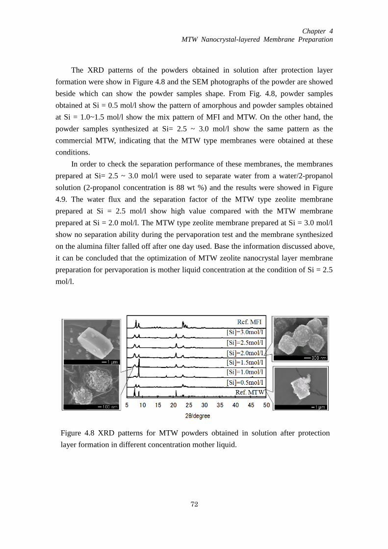
Chapter 4
MTW Nanocrystal-layered Membrane Preparation
72
The XRD patterns of the powders obtained in solution after protection layer
formation were show in Figure 4.8 and the SEM photographs of the powder are showed
beside which can show the powder samples shape. From Fig. 4.8, powder samples
obtained at Si = 0.5 mol/l show the pattern of amorphous and powder samples obtained
at Si = 1.0~1.5 mol/l show the mix pattern of MFI and MTW. On the other hand, the
powder samples synthesized at Si= 2.5 ~ 3.0 mol/l show the same pattern as the
commercial MTW, indicating that the MTW type membranes were obtained at these
conditions.
In order to check the separation performance of these membranes, the membranes
prepared at Si= 2.5 ~ 3.0 mol/l were used to separate water from a water/2-propanol
solution (2-propanol concentration is 88 wt %) and the results were showed in Figure
4.9. The water flux and the separation factor of the MTW type zeolite membrane
prepared at Si = 2.5 mol/l show high value compared with the MTW membrane
prepared at Si = 2.0 mol/l. The MTW type zeolite membrane prepared at Si = 3.0 mol/l
show no separation ability during the pervaporation test and the membrane synthesized
on the alumina filter falled off after one day used. Base the information discussed above,
it can be concluded that the optimization of MTW zeolite nanocrystal layer membrane
preparation for pervaporation is mother liquid concentration at the condition of Si = 2.5
mol/l.
Figure 4.8 XRD patterns for MTW powders obtained in solution after protection
layer formation in different concentration mother liquid.
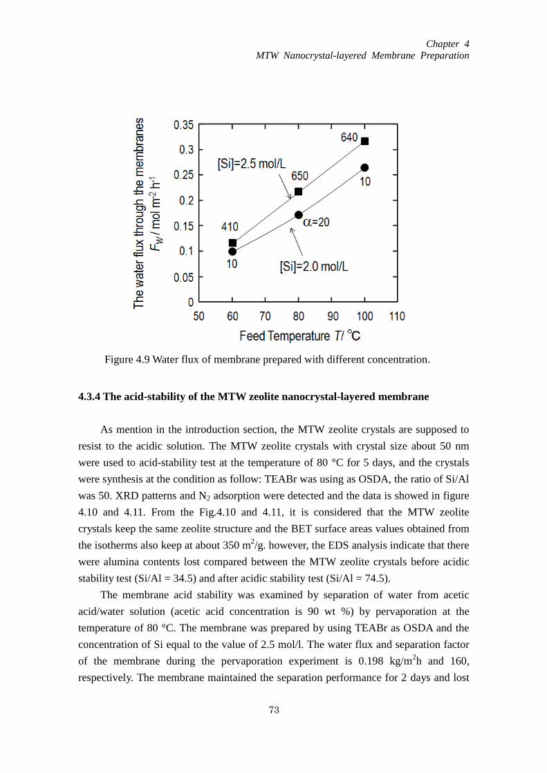
Chapter 4
MTW Nanocrystal-layered Membrane Preparation
73
4.3.4 The acid-stability of the MTW zeolite nanocrystal-layered membrane
As mention in the introduction section, the MTW zeolite crystals are supposed to
resist to the acidic solution. The MTW zeolite crystals with crystal size about 50 nm
were used to acid-stability test at the temperature of 80 °C for 5 days, and the crystals
were synthesis at the condition as follow: TEABr was using as OSDA, the ratio of Si/Al
was 50. XRD patterns and N2 adsorption were detected and the data is showed in figure
4.10 and 4.11. From the Fig.4.10 and 4.11, it is considered that the MTW zeolite
crystals keep the same zeolite structure and the BET surface areas values obtained from
the isotherms also keep at about 350 m2/g. however, the EDS analysis indicate that there
were alumina contents lost compared between the MTW zeolite crystals before acidic
stability test (Si/Al = 34.5) and after acidic stability test (Si/Al = 74.5).
The membrane acid stability was examined by separation of water from acetic
acid/water solution (acetic acid concentration is 90 wt %) by pervaporation at the
temperature of 80 °C. The membrane was prepared by using TEABr as OSDA and the
concentration of Si equal to the value of 2.5 mol/l. The water flux and separation factor
of the membrane during the pervaporation experiment is 0.198 kg/m2h and 160,
respectively. The membrane maintained the separation performance for 2 days and lost
Figure 4.9 Water flux of membrane prepared with different concentration.
mother liquid.

Chapter 4
MTW Nanocrystal-layered Membrane Preparation
74
the separation ability and the FE-SEM photographs of MTW nanocrystal-layered
membrane before and after acetic acid /water pervaporation experiment are showed in
Figure 4.12. From the figure, after 2 days acid stability test, some crystals of the MTW
membrane were dissolved but the surface is not broken. Although the acidic stability
test only assisted for 2 days, MTW type zeolite membranes are considered to be a good
candidate for the separation of acid mixtures and wide usage in organic dehydration as a
new kind of zeolite material.
Figure 4.10 XRD patterns for (a) MTW zeolite crystal before acid stability test
(b) MTW zeolite crystal after acid stability test.
Figure 4.11 Nitrogen adsorption isotherms of MTW crystals before and after
acidic stability test.

Chapter 4
MTW Nanocrystal-layered Membrane Preparation
75
4.4. Conclusions
MTW nanocrystal-layered membranes were successfully prepared using the
secondary growth method. MTW nanocrystals were laminated onto an alumina filter
and a MTW protection layer was clearly formed on the nanocrystal layer. The effect of
nanocrystal layer thickness was discussed to determine the appropriate condition for
membrane preparation. The membrane acid stability was examined by separation of
water from acetic acid/water solution (acetic acid concentration is 90 wt %) by
pervaporation.
Referrence
[1] C. Marcilly, J. Sci. 216 (2003) 47
[2] T. F. Degnan Jr, J. Cat. 216 (2003) 32
[3] V.N. Shetti, J. Kim, R. Srivastava, M. Choi, R. Ryoo, J. Cat. 254 (2008) 296
[4] K. Suzuki, Y. Aoyagi, N. Katada, M. Choi, R. Ryoo, M. Niwa, Cat. Today132 (2008)
38
[5] J.A. Rabo, M.W. Schoonover, Applied Catalysis A: General 222 (2001) 261
[6] F.J. Varela-Gandía, A. Berenguer-Murcia, D. Lozano-Castelló, D. Cazorla-Amorós,
J. Membr. Sci. 351(2010)123
[7] J. Caro, D. Albrecht, M. Noack, Sep. Purif. Technol. 66(2009)143
[8] I. Kumakiri, K. Hashimoto, Y. Nakagawa, Y. Inoue, Y. Kanehiro, K. Tanaka, H. Kita,
Catal. Today 236A (2014) 86
Figure 4.12 FE-SEM photographs of MTW nanocrystal-layered membrane surface
areas ((a) before acetic acid /water pervaporation experiment, (b) after acetic acid
/water pervaporation experiment).
Chapter 4
MTW Nanocrystal-layered Membrane Preparation
76
[9] N. Yamanaka, M. Itakura, Y. Kiyozumi, Y. Ide, M. Sadakane, T. Sano,
Micropor.Mesopor.Mater. 158 (1) (2012) 141
[10] A.M. Avila, Z. Yu, S. Fazli, J.A. Sawada, S.M. Kuznicki, Micropor. Mesopor.
Mater.190 (2014) 301.
[11] G. Li, E. Kikuchi, M. Matsukata, Sep. Purif. Technol. 32 (2003) 199
[12] P.S. Barcia, A. Ferreira, J. Gascon, S. Aguado, J.A.C. Silva, A.E. Rodrigues, F.
Kapteijn, Micropor. Mesopor. Mater. 128 (2010) 194
[13] S.M. Kumbar, T. Selvam, C. Gellermann, W. Storch, T. Ballweg, J. Breu, G. Sextl,
J. Membr. Sci. 347 (2010) 132
[14] J.B. Lee, H.H. Funke, R.D. Noble, J.L. Falconer, J. Membr. Sci.321(2) (2008) 309
[15] T. Lee, J. Choi, M. Tsapatsis, J. Membr. Sci.436 (1) (2013) 79
[16] M.O. Daramola, E.F. Aransiola, T.V. Ojumu, Materials 5 (2012) 2101
[17] S.J. Kim, S. Yang, G.K. Reddy, P. Smirniotis, J. Dong, Energy fuels 23(8) (2013)
4471
[18] Y. Morigami, M. Kondo, J. Abe, H. Kita, and K. Okamoto, Sep. Purif. Technol. 25
(2001) 251
[19] R.B. LaPierre, A.C. Rohrman Jr., J.L. Schlenker, J.D. Wood, M.K. Rubin, W.J.
Rohrbaugh, Zeolites 5 (1985) 346.
[20] M.A. Camblor, L.A. Villaescusa, M.J. Díaz-Cabaňas, Topics in Catal. 9 (1999) 59.
[21] R. Szostak, Handbook of Molecular Sieves, Van Nostrand, Reinhold, New York,
1992, p.532
[22] A. Bhaumik, M.K. Dongare, R. kumar, Micropor. Mater. 173 (1995) 5.
[23] A.V. Toktarev, K.G. Ione, Stu.Sur. Sci.Catal.105 (1997) 333
[24] S. Ritsch, N. Ohnishi, T. Ohsuna, K. Hiraga, O. Terasaki, Y. Kubota, Y. Sugi, Chem.
Mater.10 (1998) 3958.
[25] L. Dimitrov, M. Mihaylov, K. Hadjiivanov, V. Mavrodinova, Micropor.Mesopor.
Mater. 143 (2011) 291
[26] B. Gil, L. Mokrzycki, B. Sulikowski, Z. Olejniczak, S. Walas, Cat. Today
152(2010)24
[27] Y. Zhang, Y. Nakasaka, T. Tago, A. Hirata, Y. Sato, T. Masuda, Micropor. Mesopor.
Mater. 207 (2015) 39
[28] T. Tago, Y. Nakasaka, A. Kayoda, T. Masuda, Sep. Purif. Technol. 58 (2007) 7
[29] T. Tago, Y. Nakasaka, A. Kayoda, T. Masuda, Micropor. Mesopor. Mater. 115
(2008) 176
[30] T. Tago, D. Aoki, K. Iwakai, T. Masuda, Topics in Catal.52 (2009) 865
Chapter 5
Optimization of MTW Nanocrystal-layered
Membrane for Dehydration by Pervaporation
77
Chapter 5
Optimization of MTW nanocrystal-layer membrane for dehydration
by pervaporation
5.1. Introduction
During the membrane separation process, molecules in the solution are selectively
adsorbed into the membrane, permeate through it, and exit as vapor from the permeate
side. The flux of molecules through the zeolite membrane from the feed side to the
permeate side greatly affects the performance of the membrane. This flux can be
expressed as in Eq. (1), assuming that the adsorption of molecules proceeds in
accordance with a Langmuir isotherm and the effects of counter diffusion can be
ignored [1].
)( pi,fi,si,
i qqD
J
(1)
Here, , , , Di,s, qi,f and qi,p are the density, porosity and thickness of the zeolite
membrane, and the surface diffusivity and quantities of component i on the feed and
permeate sides, respectively.
According to this equation, the membrane permeability will vary with the membrane
thickness and surface diffusivity. The thickness is readily controlled by changing the
synthesis conditions used to produce the membrane, such as the amount of seed crystals
on the support filter, the Si concentration and the hydrothermal temperature. In addition,
varying the crystal size/morphology and the Si/Al ratio of the zeolite will cause the
surface diffusivity to change. There have been some reports regarding improvements in
membrane performance by controlling the crystal morphology of MOR and MFI zeolite
membranes during the secondary growth process [2-4]. In the case of MTW zeolite, the
crystal size and morphology depend on the OSDA employed. Moreover, the
hydrophilic/hydrophobic properties of an MTW zeolite membrane can be modified by
varying the aluminum content in the zeolite lattice so as to allow for the dehydration of
organic solvents [5]. Accordingly, there is the possibility of controlling the crystal
size/morphology and Si/Al ratio of MTW zeolite membranes to improve separation
properties.
The main objective of the present work is to optimization the preparation condition of
Chapter 5
Optimization of MTW Nanocrystal-layered
Membrane for Dehydration by Pervaporation
78
MTW nanocrystal layered membrane to improve the performance of the membrane and
apply it to the selective separation of water from a water/2-propanol solution by
pervaporation. Previously, we succeeded in preparing hydrophilic MFI and MOR zeolite
nanocrystal layered membranes consisting of a zeolite nanocrystal layer and a
protection layer for the removal of water from water/organic solutions [4, 6, 7]. The
application of nano-sized MTW crystal as a seed crystal was effective in improving the
membrane performance. The water flux of the layer membrane prepared using the
nanocrystals was approximately 100 times high compared with the dense membrane
prepared by in situ hydrothermal synthesis methods [2]. The protection layer is growth
from the seed layer (nanocrystal layer) during the hydrothermal synthesis. It was found
that the interface between the nanocrystal and protection layer is the densest area in the
membrane which was considered to be the main separation region of the membrane [7].
The zeolite nanocrystal in this study, the same preparation method reported previously
was applied to make the MTW zeolite membrane. As noted above, the crystal
size/morphology, Si/Al ratio and thickness of the zeolite membrane can all affect the
membrane performance, and so the effects of these parameters on the flux of water and
on the separation factor were investigated.
5.2. Experimental
5.2.1. Preparation of MTW zeolite powders and membranes
MTW nanocrystals approximately 50 nm in size were obtained via hydrothermal
synthesis with tetraethylammonium bromide (TEABr, Wako Chemicals) as the OSDA.
An aqueous solution containing sodium aluminate (Wako Chemicals), TEABr and
sodium hydroxide (Wako Chemicals) was prepared and stirred at room temperature for
3 h. Subsequently, LUDOX HS-40 colloidal silica (Si source, Aldrich Chemicals) was
added followed by further stirring at room temperature for 3 h to ensure a
homogeneous mixture. The composition ratio of the resulting mixture was
20Na2O:120TEABr:200SiO2:xAl2O3:11110H2O, where x = 1 to 2. The mixture was
transferred to a Teflon-sealed stainless steel bottle and this container was heated to
150 °C and held at this temperature for 6 days with stirring. The product was washed
thoroughly three times each with deionized water and 2-propanol and then dried
overnight at 110 °C. The OSDA was removed by calcination in air at 550
°C for 12 h.
The morphology, composition (Si/Al ratio) and crystallinity of the resulting zeolite were
assessed by field emission scanning electron microscopy (FE-SEM; JEOL JSM-6500F),

Chapter 5
Optimization of MTW Nanocrystal-layered
Membrane for Dehydration by Pervaporation
79
energy dispersive X-ray spectroscopy (EDS, JEOL JSM-6510LA) and X-ray diffraction
(XRD; JEOL JDX-8020), respectively. The porous and Brunauer-Emmett-Teller (BET)
surface areas of the zeolite were determined from N2 adsorption isotherms
(BELSORP-mini).
The MTW nanocrystals were subsequently ultrasonically dispersed in a sodium
hydroxide aqueous solution (approximately pH 12) at concentrations of 3.5 to 6.5 g·m-3
.
The dispersed nanocrystals were layered on the outer surfaces of cylindrical alumina
ceramic filters (NGK insulators) via a filtration method driven by the application of a
vacuum to the permeate side. The inner and outer diameters and the length of the filters
were 6, 11 and 50 mm, respectively. Each filter consisted of two porous regions; an
inner region with a pore diameter of approximately 2-3 μm (the rough region) and a
dense outer region with a pore diameter of 0.1 μm. Each filter was immersed in 0.1 M
HCl for 6 h and then washed in distilled water prior to preparation of the membranes.
The thickness of the MTW nanocrystal layer on the ceramic filter could be controlled by
changing the concentration of nanocrystals in the sodium hydroxide aqueous solution.
Finally, to protect the nanocrystal layer against mechanical shock, a protection layer was
hydrothermally formed on the nanocrystal layer using either TEABr or
methyltriethylammonium chloride (MTEACl, Tokyo Chemical Industry) as the OSDA.
The composition of the synthesis mixture when using TEABr as the OSDA was
20Na2O:100TEABr:500SiO2:xAl2O3:11110H2O, where x = 1.25 to 5, while the
composition with MTEACl was 20Na2O:60TEABr:300SiO2:5Al2O3:11110H2O. The
aqueous solution containing the MTW nanocrystal-layered membrane was heated to
150 °C for 6 days to form a protection layer on the nanocrystal layer. The zeolite
membrane thus prepared was washed with distilled water and then dried in air. Further
details of this process have been provided previously [6, 7].
5.2.2. Pervaporation trials
Pervaporation trials were carried out using a conventional method at temperatures
ranging from 60 to 100 °C in a stainless steel autoclave, with water/2-propanol
(2-propanol concentration is 88 wt%) as the feed solution. After the membrane was
immersed in this solution, the air in the autoclave was replaced with room temperature
nitrogen and the vessel was heated to the desired pervaporation temperature. Molecules
permeating through the membrane were swept out with a flow of nitrogen that was
continuously fed to the permeate side of the membrane. The composition of the exit gas
from the permeate side was analyzed using an on-line gas chromatograph equipped with
Chapter 5
Optimization of MTW Nanocrystal-layered
Membrane for Dehydration by Pervaporation
80
a molecular sieve 5Å column and TCD and FID detectors. Details of this procedure
have been described in previous reports [6, 7].
The separation factor, , was defined as
where Fw and Fi are the molar flux of water and 2-propanol on the permeate side,
respectively, and Cw and Ci are the molar concentrations of water and 2-propanol on the
feed side, respectively.
The membrane separation ability and water flux are tested to become stable after
the pervaporation test carried out for 5 h in the same temperature. Therefore, all of the
pervaporation data were detected in the membrane stable condition (after 5 h
pervaporation experiment in the same temperature). The duration of the every test was 8
h and after each pervaporation test, the membrane was at first washed by water and then
dried in air for 12 h. The total amount of water and organic solvent permeating through
the membrane during each experiment was less than 3 wt%. Accordingly, the initial
concentrations were used to calculate the separation factor.
5.3. Results and discussion
5.3.1. Effect of crystal size in the protection layer on separation properties
In our previous study of the hydrophilic silicalite-1 nanocrystal-layered membrane
and mordernite membrane, the water-silanol networks that formed on non-zeolitic pore
spaces among the crystals acted as one of the main channel for water permeation, and
the interface between the nanocrystal layer and protection layer was important for the
separation because this area became the densest area in the membrane [4, 6]. The
morphology and crystal size around the interface formed by hydrothermal synthesis are
the important factors affecting the membrane permeability and separation ability.
Therefore, the effects of the crystal size and morphology of the protection layer on
the water separation from water/2-propanol solutions were examined by pervaporation.
The membranes were prepared by the same method as show in the last chapter (chapter
4, result and discussion 4.3.2) and the resulting water flux and separation factor data
obtain in the pervaporation test are summarized in Fig. 5.1. The layered membrane with
nanocrystals in the protection layer (prepared using TEABr) exhibited a much higher
separation factor and a water flux more than four times that of the membrane with
iw
iw
CC
FF
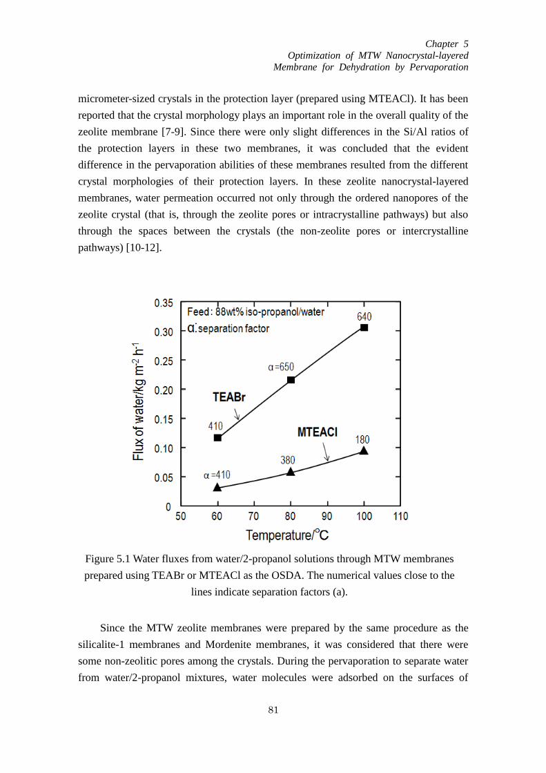
Chapter 5
Optimization of MTW Nanocrystal-layered
Membrane for Dehydration by Pervaporation
81
micrometer-sized crystals in the protection layer (prepared using MTEACl). It has been
reported that the crystal morphology plays an important role in the overall quality of the
zeolite membrane [7-9]. Since there were only slight differences in the Si/Al ratios of
the protection layers in these two membranes, it was concluded that the evident
difference in the pervaporation abilities of these membranes resulted from the different
crystal morphologies of their protection layers. In these zeolite nanocrystal-layered
membranes, water permeation occurred not only through the ordered nanopores of the
zeolite crystal (that is, through the zeolite pores or intracrystalline pathways) but also
through the spaces between the crystals (the non-zeolite pores or intercrystalline
pathways) [10-12].
Since the MTW zeolite membranes were prepared by the same procedure as the
silicalite-1 membranes and Mordenite membranes, it was considered that there were
some non-zeolitic pores among the crystals. During the pervaporation to separate water
from water/2-propanol mixtures, water molecules were adsorbed on the surfaces of
Figure 5.1 Water fluxes from water/2-propanol solutions through MTW membranes
prepared using TEABr or MTEACl as the OSDA. The numerical values close to the
lines indicate separation factors (a).

Chapter 5
Optimization of MTW Nanocrystal-layered
Membrane for Dehydration by Pervaporation
82
zeolitic and non-zeolitic pores, on which the water adsorption layer was formed, were
the important channel for water permeation. The water molecules can diffuse through
the non-zeolitic pore surrounded by the water adsorption layer, and consequently the
size of non-zeolitic pores mainly affects the separation properties. The MTW membrane
prepared using TEABr would possess a larger number of intercrystalline pores among
the crystals, the pore size of which was appropriate for water selective permeation,
compared with the membrane prepared using MTEACl. The larger number of pores and
the smaller crystal size increased the water permeation rate through the intercrystalline
and intracrystalline pathways within the membrane, respectively. Accordingly, the
nanocrystal-layered membrane with a nano-crystalline protection layer prepared using
TEABr exhibited higher water flux and enhanced separation ability compared with the
membrane prepared using MTEACl.
5.3.2. Effects of the Si/Al ratio on the membrane performance
In a zeolite membrane, its hydrophilicity/hydrophobicity, which depends on the
Si/Al ratio, affects the adsorbed quantity and diffusivity of molecules permeating
through the membrane [13]. These MTW nanocrystal-layered membranes were
composed of a nanocrystal layer and a protection layer, and so the Si/Al ratio of the
MTW zeolite in both layers was expected to affect the membrane properties.
Accordingly, MTW zeolite membranes with different Si/Al ratios in the nanocrystal and
protection layers were prepared, and the effects of the ratio on the separation ability (as
assessed by the water flux and separation factor) were examined. The membrane
synthesis conditions and the Si/Al ratios in the nanocrystal and protection layers are
listed in Table 5.1, along with the pervaporation results.
The pervaporation results for specimens M1, M2 and M3 show that the water flux
varied with the Si/Al ratio in the protection layer, which was controlled by changing the
Si/Al ratio of the mother liquid. With increasing aluminum content in the protection
layer (while holding the Si/Al ratio in the nanocrystal layer at 34.5), the water flux was
increased, and maintaining a high separation factor. Moreover, all of the membrane (M1,
M2 and M3) show the highest separation ability at pervaporation temperature of 80 °C,
and show the decreasing trend to 100 °C. This is because when the pervaporation
temperature reach up to the boiling point of water, the water adsorption layer formed on
the outside of the non-zeolitic pore will become unstable or broken and the non-zeolitic
pores without the water adsorption layer will lose the selectivity leading to decrease in
membrane separation ability.
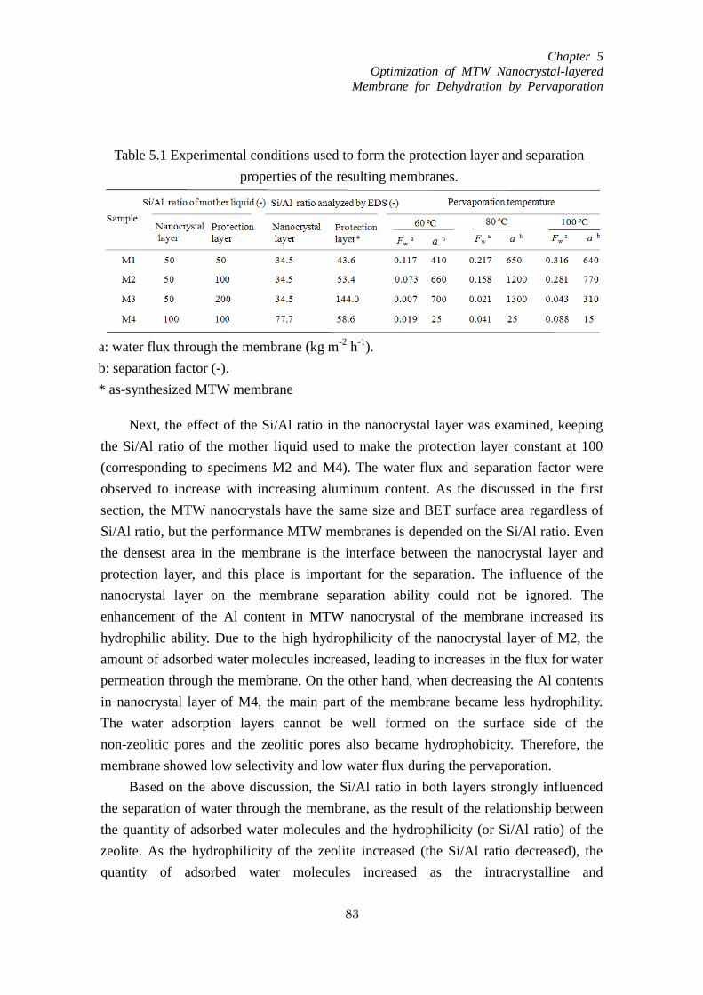
Chapter 5
Optimization of MTW Nanocrystal-layered
Membrane for Dehydration by Pervaporation
83
Next, the effect of the Si/Al ratio in the nanocrystal layer was examined, keeping
the Si/Al ratio of the mother liquid used to make the protection layer constant at 100
(corresponding to specimens M2 and M4). The water flux and separation factor were
observed to increase with increasing aluminum content. As the discussed in the first
section, the MTW nanocrystals have the same size and BET surface area regardless of
Si/Al ratio, but the performance MTW membranes is depended on the Si/Al ratio. Even
the densest area in the membrane is the interface between the nanocrystal layer and
protection layer, and this place is important for the separation. The influence of the
nanocrystal layer on the membrane separation ability could not be ignored. The
enhancement of the Al content in MTW nanocrystal of the membrane increased its
hydrophilic ability. Due to the high hydrophilicity of the nanocrystal layer of M2, the
amount of adsorbed water molecules increased, leading to increases in the flux for water
permeation through the membrane. On the other hand, when decreasing the Al contents
in nanocrystal layer of M4, the main part of the membrane became less hydrophility.
The water adsorption layers cannot be well formed on the surface side of the
non-zeolitic pores and the zeolitic pores also became hydrophobicity. Therefore, the
membrane showed low selectivity and low water flux during the pervaporation.
Based on the above discussion, the Si/Al ratio in both layers strongly influenced
the separation of water through the membrane, as the result of the relationship between
the quantity of adsorbed water molecules and the hydrophilicity (or Si/Al ratio) of the
zeolite. As the hydrophilicity of the zeolite increased (the Si/Al ratio decreased), the
quantity of adsorbed water molecules increased as the intracrystalline and
Table 5.1 Experimental conditions used to form the protection layer and separation
properties of the resulting membranes.
a: water flux through the membrane (kg m-2
h-1
).
b: separation factor (-).
* as-synthesized MTW membrane

Chapter 5
Optimization of MTW Nanocrystal-layered
Membrane for Dehydration by Pervaporation
84
intercrystalline pores within the membrane were filled with water molecules, leading to
the enhanced separation properties. Moreover, since the crystal morphology of the
protection layer and the Si/Al ratios in the protection and nanocrystal layers affected the
separation properties, both layers played important roles in water separation from
water/2-propanol mixtures by pervaporation.
5.3.3. Effect of the nanocrystal layer thickness on membrane permeation
properties
Those membranes with high fluxes and good separation abilities were deemed to
have regions suitable for separation. As discussed above, the results indicated that
separation in the membranes prepared using TEABr as the OSDA for the protection
layer occurred both in the area close to the outer surface (the protection layer) and in the
MTW nanocrystal layer. In order to prepare membranes with suitable separation areas,
the effect of the nanocrystal layer thickness on the separation properties of the
membranes were also investigated. In these trials, the layer thickness was controlled by
varying the concentration of nanocrystals in a sodium hydroxide aqueous solution while
loading the alumina filter. The second growth of the protection layer is mainly happened
on the surface of the nanocrystal layer since it directly connected with the mother liquid
during the hydrothermal synthesis. Therefore, the effect of the nanocrystal layer
thickness on the growth of the protection layer is considered to be small or can be
ignored. In this manner, membranes with nanocrystal layer thicknesses of 7.5, 10, 12
and 17 μm were prepared, maintain the Si/Al ratio in the nanocrystals and in the mother
liquid employed to make the protection layer at 50. Fig. 5.2 presents cross-sectional
FE-SEM images of the resulting membranes. An MTW zeolite layer consisting of dense
nanometer-sized crystals was evidently formed over the outer surface of each membrane.
Fig. 5.3 shows the effects of the nanocrystal layer thickness on the water flux through
the layered membranes and on the separation factor (α). This figure demonstrates that
the water flux increased as the thickness of the nanocrystal layer decreased. In contrast,
the separation factor increased with increasing thickness and plateaued at values as high
as approximately 1200 at thicknesses above 12 μm. This result indicated that both the
flux and separation ability were dependent on the amount of nanocrystals loaded on the
alumina filter. Thus it is considered that membrane regions that supported the selective
permeation of water were formed during the second growth process. During the
pervaporation to separate water from water/2-propanol mixtures, water molecules were
adsorbed on the ion-exchange sites of zeolitic and non-zeolitic pores in the MTW
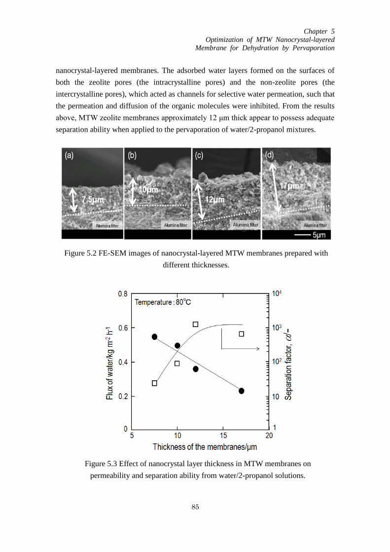
Chapter 5
Optimization of MTW Nanocrystal-layered
Membrane for Dehydration by Pervaporation
85
nanocrystal-layered membranes. The adsorbed water layers formed on the surfaces of
both the zeolite pores (the intracrystalline pores) and the non-zeolite pores (the
intercrystalline pores), which acted as channels for selective water permeation, such that
the permeation and diffusion of the organic molecules were inhibited. From the results
above, MTW zeolite membranes approximately 12 μm thick appear to possess adequate
separation ability when applied to the pervaporation of water/2-propanol mixtures.
Figure 5.2 FE-SEM images of nanocrystal-layered MTW membranes prepared with
different thicknesses.
Figure 5.3 Effect of nanocrystal layer thickness in MTW membranes on
permeability and separation ability from water/2-propanol solutions.
Chapter 5
Optimization of MTW Nanocrystal-layered
Membrane for Dehydration by Pervaporation
86
5.4. Conclusions
MTW-type zeolite membranes composed of a nanocrystal layer and a protection
layer were successfully prepared by a secondary growth method and pervaporation trials
involving the separation of water from water/2-propanol solutions were conducted to
evaluate their performance. The crystal size of the MTW zeolite in the protection layer
could be controlled by using different OSDA molecules (TEABr and MTEACl). The
MTW membranes prepared using TEABr showed dense layers composed of
nanometer-sized crystals and also exhibited higher water flux values as well as
enhanced separation factors compared to the membranes prepared using MTEACl. The
Al content in both the protection and nanocrystal layers was found to affect the
performance of the membranes, such that MTW membranes with high aluminum
contents showed elevated water fluxes. Moreover, the membrane flux was determined to
depend on the thickness of the membrane, such that the water flux increased with
decreasing thickness. It is believed that both the protection and nanocrystal layers are
important factors in determining the membrane performance, and that comparatively
thin membranes with high Al contents will provide the highest water flux values during
the separation of water from water/2-propanol mixtures.
Reference
[1] D. Shah, K. Kissick, A. Ghorpade, R. Hannah, and D. Bhattacharyya, J. Membr. Sci.
179 (2000) 185
[2] M. Matsukata, K. Sawamura, T. Shirai, M. Takada, Y. Sekine, E. Kikuchi, J. Membr.
Sci.316 (2008) 27
[3] G. Li, E. Kikuchi, M. Matsukata, Micropor. Mesopor. Mater. 62 (2003) 218
[4] Y. Zhang, Y. Nakasaka, T. Tago, A. Hirata, Y. Sato, T. Masuda, Micropor. Mesopor.
Mater. 207 (2015) 39
[5] J. Coronas, J. Santamaria, Sep. Purif. Methods 28 (1999) 127
[6] T. Tago, Y. Nakasaka, A. Kayoda, T. Masuda, Sep. Purif. Technol.58 (2007) 7
[7] T. Tago, Y. Nakasaka, A. Kayoda, T. Masuda, Micropor. Mesopor. Mater. 115 (2008)
176
[8] J.B. Lee, H.H. Funke, R.D. Noble, J.L. Falconer, J. Membr. Sci.321(2) (2008) 309
[9] T.C. Bowen, R.D. Noble, J.L. Falconer, J. Membr. Sci. 245 (2004) 15
[10] M. Nomura, T. Yamaguchi, S. Naka, J. Membr. Sci. 187 (2001) 203

Chapter 5
Optimization of MTW Nanocrystal-layered
Membrane for Dehydration by Pervaporation
87
[11] A.K. Pabby, S.S.H.Rizvi, A. M. Sastre, Handbook of Membrane Separations, 2008,
P289
[12] T.C. Bowen, H. Kalipcilar, J.L. Falconer, R.D. Noble, J. Membr. Sci. 215 (2003)
235
[13] M. Noack, P. Kölsch, V. Seefeld, P. Toussaint, G. Georgi, J. caro, Micropor.
Mesopor. Mater.79 (2005) 329

Chapter 6
ZIF-8 Membrane Preparation
88
Chapter 6
ZIF-8 membrane preparation
6.1. Introduction
Zeolitic imidazolate frameworks (ZIFs) are a subclass of MOFs which are
composed of tetrahedrally-coordinated transition metal ions (e.g. Fe, Co, Cu, Zn)
connected by organic imidazole linkers. Since the metal-imidazole-metal angle is
similar to the 145° Si-O-Si angle in zeolites, ZIFs take on zeolite-like topologies.
Moreover, ZIFs possess the advantages of both zeolites and MOFs, such as large surface
areas, high crystallinities and exceptional thermal and chemical stabilities. ZIFs hold
great promise in many application areas including catalysis, separation and sensing
[1-3].
ZIF materials possess promising future and can be applied in many areas. ZIF
based membranes using for separation is one of the most attractive applications and
different kinds of ZIFs membrane have been developed for different kind separation
processes [4-10]. So far, various synthesis methods for ZIF membranes have been
explored. Generally, the preparation method can be classified into three categories: in
situ preparation [11], secondary growth preparation [12] and the counter-diffusion
preparation [13].
The remaining challenge is to produce ZIFs on a large scale to meet the potential
commercial application and the methods for ZIFs membrane which with high
reproducibility, scalability and cost-effectiveness in the future. The present work
focuses on the synthesis, characterization, and the performance of ZIF-8
nanocrystal-layer membrane by selective separation of organic from water/organci
mixtures. We have also studied the permeance of organic molecules through ZIF-8
membrane and application for the separation organic/water solution by pervaporation.
6.2. Experimental
6.2.1. Synthesis of ZIF-8 membranes
ZIF-8 was synthesized by mixing 2-methylimidazole (Hmim, Sigma-Aldrich) with
Chapter 6
ZIF-8 Membrane Preparation
89
Zn nitrate hexahydrate (Zn(NO3)2•6H2O, Sigma-Aldrich) in the presence of the
nonionic surfactant in the water solution. A water solution containing
polyoxyethylene-(15)-oleylether (O-15, Nikko Chemicals), and 2-methylimidazole
(Sigma-Aldrich) stirred until the surfactant dissolved. After that, zinc nitrate water
solutions were then added into the Hmim solution and kept stirring for 24 h at room
temperature. The Zn+: Hmim: surfactant: water molar ratio of the solution was 1: 40:
0.01: 2210.
A cylindrical alumina ceramic filter (NGK insulators, LTD.) was used as a
membrane support. The inner and outer diameters and the length of the filter were 6 mm,
11 mm, and 50 mm, respectively. This filter was constructed in two porous regions; the
pore diameter of the inner region was about 2-3 μm (rough region), and the outer region
was dense and its pore diameter was 0.1μm. The filter was immersed in a 0.1 N
hydrochloride solution for 6 h, and washed in distilled water. The ZIF-8 nanocrystals
were dispersed ultrasonically in an ethanol solution at a concentration of 2-13 g·m-3
.
The dispersed nanocrystals were layered on the outer surface of cylindrical alumina
ceramic filters using a filtration method under low-pressure vacuum on the permeate
side. The thickness of the nanocrystal layer is about 4-22 μm. To protect the nanocrystal
layer against mechanical shock, a protection layer with micrometer-sized ZIF-8 was
formed hydrothermally (secondary growth) on the nanocrystal layer without surfactant
(O-15). An aqueous solution (mother liquid) containing Zn+ and Hmim sources prepared
by of Zn(NO3)2•6H2O and 2-methylimidazole was used to form the protection layer and
the molar composition was: Zn+: Hmim: surfactant: water molar ratio of the solution
was 1: 70: 4420x, where x equal to 2 to 4.
Then the alumina filter with a ZIF-8 nanocrystal layer was immersed in the
precursor solution and kept at the room temperature for 24 h to form the protection layer
on the nanocrystal layer.
6.2.2. Analysis method
The powders obtained in the solution during hydrothermal synthesis for the
protection layer of ZIF-8 membrane were characterized by X-ray diffraction (XRD,
JEOL JDX-8030), thermogravimetry analysis (TGA) and nitrogen adsorption and
desorption experiment. The membrane morphology was characterized by scanning
electron microscopy (SEM, JEOL JSM-6500F).
6.2.3. Pervaporation trials
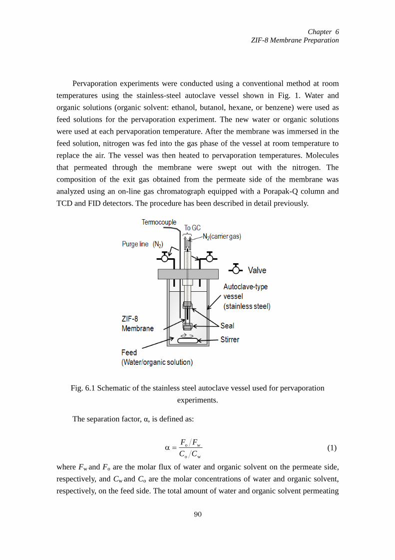
Chapter 6
ZIF-8 Membrane Preparation
90
Pervaporation experiments were conducted using a conventional method at room
temperatures using the stainless-steel autoclave vessel shown in Fig. 1. Water and
organic solutions (organic solvent: ethanol, butanol, hexane, or benzene) were used as
feed solutions for the pervaporation experiment. The new water or organic solutions
were used at each pervaporation temperature. After the membrane was immersed in the
feed solution, nitrogen was fed into the gas phase of the vessel at room temperature to
replace the air. The vessel was then heated to pervaporation temperatures. Molecules
that permeated through the membrane were swept out with the nitrogen. The
composition of the exit gas obtained from the permeate side of the membrane was
analyzed using an on-line gas chromatograph equipped with a Porapak-Q column and
TCD and FID detectors. The procedure has been described in detail previously.
The separation factor, α, is defined as:
wo
o
CC
FF w (1)
where Fw and Fo are the molar flux of water and organic solvent on the permeate side,
respectively, and Cw and Co are the molar concentrations of water and organic solvent,
respectively, on the feed side. The total amount of water and organic solvent permeating
Fig. 6.1 Schematic of the stainless steel autoclave vessel used for pervaporation
experiments.
Chapter 6
ZIF-8 Membrane Preparation
91
through the membrane during each experiment was less than 3%. Accordingly, the
initial concentrations of Cw and Co were used to calculate the separation factor.
The permeance, Pi, is defined as:
i
ii
C
FP (2)
Fi is the molar flux of water or organic molecules that permeate through the
mordenite nanocrystal-layer membrane and Ci stands for the molar concentration of
water or organic solvent in the feed side solution. The permeance indicated the
permeability of the component (water or organic molecules) in the organic solution
through the ZIF-8 nanocrystal-layer membrane.
6.3. Results and discussion
6.3.1. Synthesis of ZIF-8 crystals
ZIF-8 crystals were synthesized at room temperature using O-15 as surfactant.
Figure 6.2 shows XRD patterns of white powders obtained, which showed patterns
corresponding to ZIF-8. Figure 6.3 shows FE-SEM photographs of obtained ZIF-8
crystals. Round shape small crystals with size of approximately 50 nm were formed.
Nitrogen adsorption isotherms of the obtained ZIF-8 were measured at 77 K (Fig.
6.4). The isotherms exhibited Type-I behavior according Langmuir isotherm model,
which reflects the presence of micropore. Brunauer-Emmett-Teller (BET) surface area
obtained from the isotherms were about 1770 m2/g which value is in good agreement
with those of previously reported data [14]. Figure 6.5 shows gas adsorption result,
where water, ethanol, butanol, n-hexane and benzene were used. From the figure, the
ZIf-8 shows an only very low uptake of water, and the vapour-phase adsorption
isotherms of ethanol and butanol show an S-shaped profiles. On the other hand, benzene
and n-hexane exhibited Type-I behavior according Langmuir isotherm model.
These ZIF-8 nanocrystals thus obtained were used for ZIF-8 membrane
preparation.
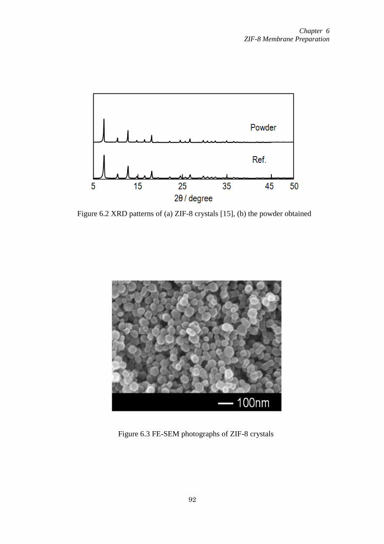
Chapter 6
ZIF-8 Membrane Preparation
92
Figure 6.2 XRD patterns of (a) ZIF-8 crystals [15], (b) the powder obtained
Figure 6.3 FE-SEM photographs of ZIF-8 crystals
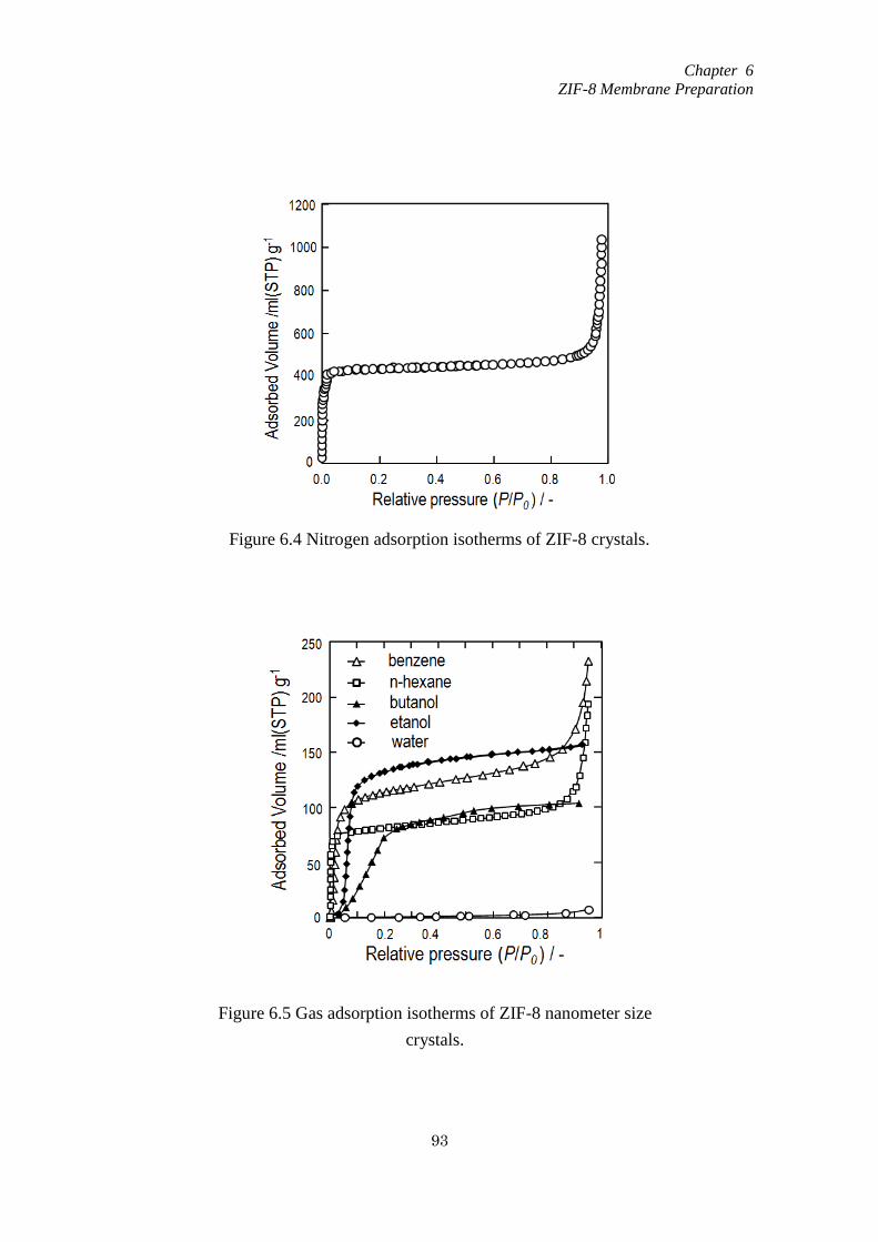
Chapter 6
ZIF-8 Membrane Preparation
93
Figure 6.4 Nitrogen adsorption isotherms of ZIF-8 crystals.
Figure 6.5 Gas adsorption isotherms of ZIF-8 nanometer size
crystals.

Chapter 6
ZIF-8 Membrane Preparation
94
6.3.2 ZIF-8 membrane prepared by second growth method
After the ZIF-8 nanocrystals were piled up on the aluminum ceramic filter,
protection layer of the membranes were synthesized at room temperature. In order to
prepare the membranes with appropriate separation areas, the effect of the nanocrystals
layer thickness onto the separation properties of the membranes were investigated. The
thickness was controlled by changing the concentrations of nanocrystals in the ethanol
solution piling up on the alumina filter.
ZIF-8 membranes with nanocrystal layer thickness of 4.1, 5.6, 16.8 and 22μm were
prepared. Figure 6.6 shows FE-SEM photographs of the cross sectional area of the
membranes. A ZIF-8 membranes consists of dense micro meter sized crystals have been
formed on the top of the outer surface of membrane when the nanocrystal layer equal to
5.6, 16.8 and 22μm, respectively and the thickness of the protection layer is nearly the
same.
Figure 6.6 FE-SEM photographs of ZIF-8 membranes prepared with different
thickness (a) cross section area, (b) protection layer by large magnification, and (c)
top view.
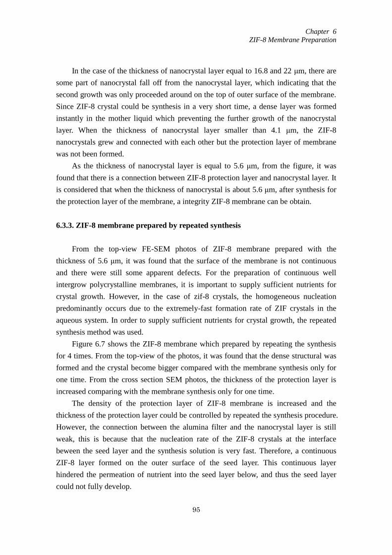
Chapter 6
ZIF-8 Membrane Preparation
95
In the case of the thickness of nanocrystal layer equal to 16.8 and 22 μm, there are
some part of nanocrystal fall off from the nanocrystal layer, which indicating that the
second growth was only proceeded around on the top of outer surface of the membrane.
Since ZIF-8 crystal could be synthesis in a very short time, a dense layer was formed
instantly in the mother liquid which preventing the further growth of the nanocrystal
layer. When the thickness of nanocrystal layer smaller than 4.1 μm, the ZIF-8
nanocrystals grew and connected with each other but the protection layer of membrane
was not been formed.
As the thickness of nanocrystal layer is equal to 5.6 μm, from the figure, it was
found that there is a connection between ZIF-8 protection layer and nanocrystal layer. It
is considered that when the thickness of nanocrystal is about 5.6 μm, after synthesis for
the protection layer of the membrane, a integrity ZIF-8 membrane can be obtain.
6.3.3. ZIF-8 membrane prepared by repeated synthesis
From the top-view FE-SEM photos of ZIF-8 membrane prepared with the
thickness of 5.6 μm, it was found that the surface of the membrane is not continuous
and there were still some apparent defects. For the preparation of continuous well
intergrow polycrystalline membranes, it is important to supply sufficient nutrients for
crystal growth. However, in the case of zif-8 crystals, the homogeneous nucleation
predominantly occurs due to the extremely-fast formation rate of ZIF crystals in the
aqueous system. In order to supply sufficient nutrients for crystal growth, the repeated
synthesis method was used.
Figure 6.7 shows the ZIF-8 membrane which prepared by repeating the synthesis
for 4 times. From the top-view of the photos, it was found that the dense structural was
formed and the crystal become bigger compared with the membrane synthesis only for
one time. From the cross section SEM photos, the thickness of the protection layer is
increased comparing with the membrane synthesis only for one time.
The density of the protection layer of ZIF-8 membrane is increased and the
thickness of the protection layer could be controlled by repeated the synthesis procedure.
However, the connection between the alumina filter and the nanocrystal layer is still
weak, this is because that the nucleation rate of the ZIF-8 crystals at the interface
beween the seed layer and the synthesis solution is very fast. Therefore, a continuous
ZIF-8 layer formed on the outer surface of the seed layer. This continuous layer
hindered the permeation of nutrient into the seed layer below, and thus the seed layer
could not fully develop.

Chapter 6
ZIF-8 Membrane Preparation
96
6.3.4. The density of the nanocrystal layer
A counter diffusion method is using the supports physically separate the metal ions
from the ligand molecules. This method enables the synthesis membranes to be healed
readily which made the poorly inter-grown membranes to be healed.
In order to increase the density of the nanocrystal layer and strengthen the
connection between the nanocrystal layer and alumina filter. The counter diffusion
method is carried out. After pile up the nanocrystals on the surface of the alumina filter,
the counter diffusion method is conducted, and then the hydrothermal synthesis for the
protection layer of the ZIF-8 membrane. Figure 6.8 shows the ZIF-8 membrane
prepared with the counter diffusion method to modify the density of the nanocrystal
layer. From the SEM photoes (cross section), the protection layer was formed on the
nanocrystal layer and the connection between the nanocrysal layer and alumina filter is
closely, the boundary could not be distinguished clearly.
Figure 6.7 FE-SEM photographs of ZIF-8 membranes prepared by repeated
synthesis. (a) cross section area, (b) top view.
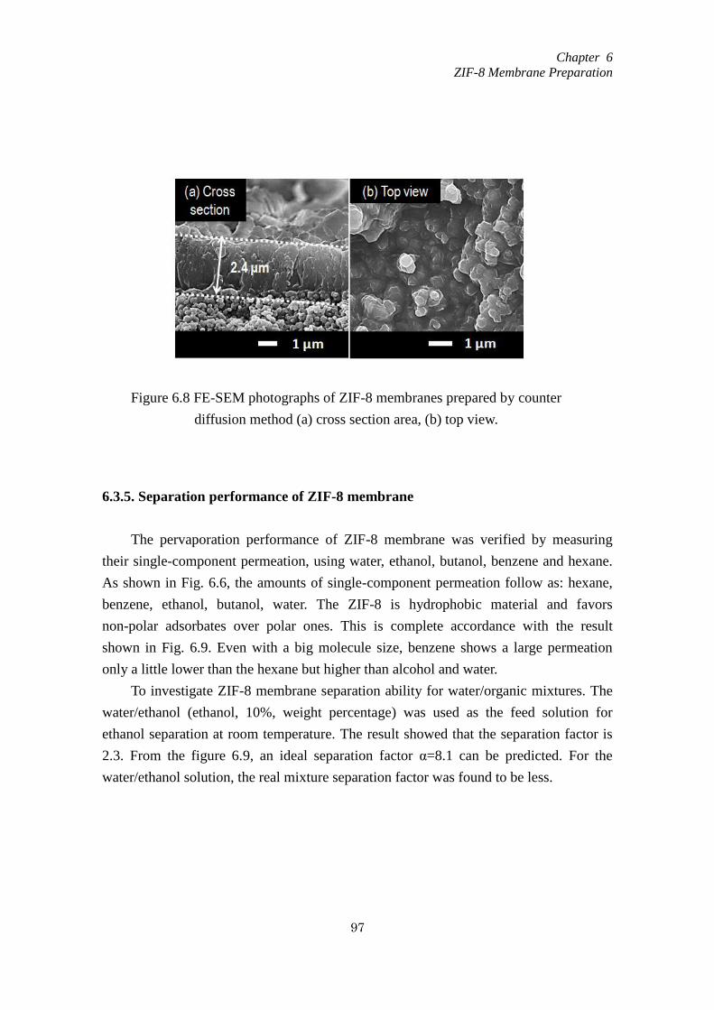
Chapter 6
ZIF-8 Membrane Preparation
97
6.3.5. Separation performance of ZIF-8 membrane
The pervaporation performance of ZIF-8 membrane was verified by measuring
their single-component permeation, using water, ethanol, butanol, benzene and hexane.
As shown in Fig. 6.6, the amounts of single-component permeation follow as: hexane,
benzene, ethanol, butanol, water. The ZIF-8 is hydrophobic material and favors
non-polar adsorbates over polar ones. This is complete accordance with the result
shown in Fig. 6.9. Even with a big molecule size, benzene shows a large permeation
only a little lower than the hexane but higher than alcohol and water.
To investigate ZIF-8 membrane separation ability for water/organic mixtures. The
water/ethanol (ethanol, 10%, weight percentage) was used as the feed solution for
ethanol separation at room temperature. The result showed that the separation factor is
2.3. From the figure 6.9, an ideal separation factor α=8.1 can be predicted. For the
water/ethanol solution, the real mixture separation factor was found to be less.
Figure 6.8 FE-SEM photographs of ZIF-8 membranes prepared by counter
diffusion method (a) cross section area, (b) top view.
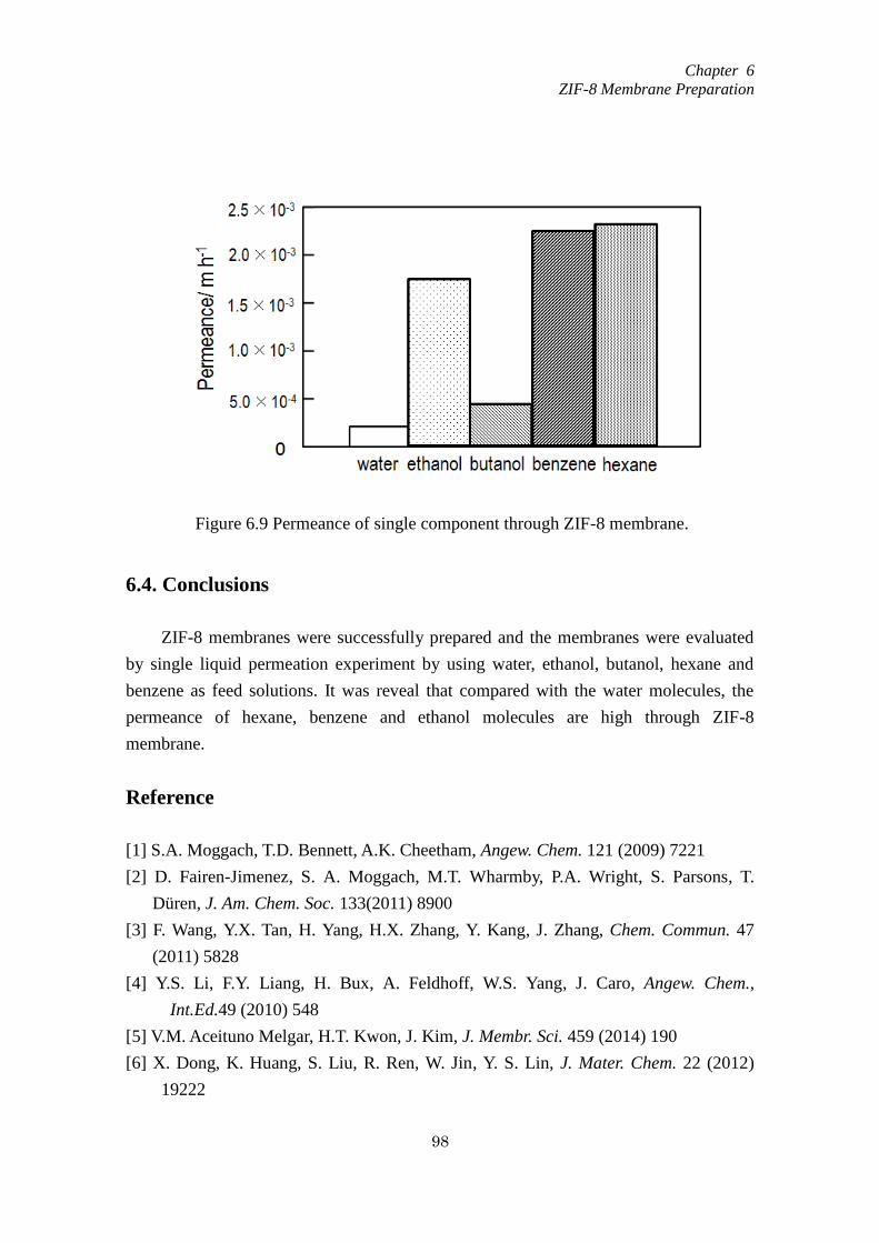
Chapter 6
ZIF-8 Membrane Preparation
98
6.4. Conclusions
ZIF-8 membranes were successfully prepared and the membranes were evaluated
by single liquid permeation experiment by using water, ethanol, butanol, hexane and
benzene as feed solutions. It was reveal that compared with the water molecules, the
permeance of hexane, benzene and ethanol molecules are high through ZIF-8
membrane.
Reference
[1] S.A. Moggach, T.D. Bennett, A.K. Cheetham, Angew. Chem. 121 (2009) 7221
[2] D. Fairen-Jimenez, S. A. Moggach, M.T. Wharmby, P.A. Wright, S. Parsons, T.
Düren, J. Am. Chem. Soc. 133(2011) 8900
[3] F. Wang, Y.X. Tan, H. Yang, H.X. Zhang, Y. Kang, J. Zhang, Chem. Commun. 47
(2011) 5828
[4] Y.S. Li, F.Y. Liang, H. Bux, A. Feldhoff, W.S. Yang, J. Caro, Angew. Chem.,
Int.Ed.49 (2010) 548
[5] V.M. Aceituno Melgar, H.T. Kwon, J. Kim, J. Membr. Sci. 459 (2014) 190
[6] X. Dong, K. Huang, S. Liu, R. Ren, W. Jin, Y. S. Lin, J. Mater. Chem. 22 (2012)
19222
Figure 6.9 Permeance of single component through ZIF-8 membrane.
Chapter 6
ZIF-8 Membrane Preparation
99
[7] M.C. McCarthy, V. Varela-Guerrero, G.V. Barnett, H.K. Jeong, Langmuir 26 (2010)
14636
[8] L. Ge, A. Du, M. Hou, V. Rudolph, Z. Zhu, RSC Adv. 2(2012) 11793
[9] Y. Pan, Z. Lai, Chem. Commun. 47 (2011) 10275
[10] N. Hara, M. Yoshimune, H. Negishi, K. Haraya, S. Hara, T. Yamaguchi, J. Membr.
Sci. 450 (2014) 215
[11] H. Bux, F. Liang, Y. Li, J. Cravillon, M. Wiebcke, J.R. Caro, J. Am. Chem. Soc. 131
(2009) 16000
[12] S.R. Venna, M.A. Carreon, J. Am. Chem. Soc. 132 (2009) 76
[13] N. Hara, M. Yoshimune, H. Negishi, K. Haraya, S. Hara, T. Yamaguchi, J. Membr.
Sci. 450 (2014) 215
[14] T. Xing, Y. Lou, Q. Bao, J. Chen, CrystEngComm 16 (2014) 8994
[15] Y. Pan, Y. Liu, G. Zeng, L. Zhao, Z. Lai, Chem. Commun. 47 (2011) 2071

Summary
100
Summary
In chemical processes, liquid mixtures are usually separated by distillation, which
utilizes the vapor-liquid equilibrium difference. Purification of chemicals derived from
biomass, such as ethanol, acetic acid, and acetone, requires a distillation column with a
large number of plates and a high reflux ratio, plus a complex process for purification of
azeotropes, which consumes a large amount of energy. Thus, a new high-purity,
low-energy consumption separation process is needed. A pervaporation is a promising
technique to achieve this goal and the pervaopration technique by using membrane is
proposed.
The membrane process can separate certain molecular mixtures effectively and
economically without any toxic or by-production. The materials used for membrane
preparation are not limited but cover in a wide range. The structures and properties of
the materials decided the membrane performance and the field of membrane
applications. This research is focus on developing the new kinds of the membranes with
different structure zeolite crystals and ZIFs crystals. The mordenite and MTW type
zeolite which the Si/Al ratio can be controlled over a wide range of values were used for
synthesis of the membrane. Moreover, ZIFs possess the advantages of both zeolites and
MOFs, such as large surface areas, high crystallinities and exceptional thermal and
chemical stabilities were also selected to synthesis of the membrane. The membrane
preparation method and optimization of the membrane preparation for separation of
water from water/organic mixtures by pervaporation were discussed in the works.
Summary of each chapter explain as follows.
In chapter 1, the different kind of porous materials and the development of porous
materials based membrane were introduced. The zeolite molecular sieve and the
representative structure of zeolites, such as zeolite A, zeolite ZSM-5 and Mordenite
were presented. The application of the zeolite crystal especially the zeolite used for
separation is referred to get a better understanding of the zeolite crystal. The basic
knowledge of the zeolite membrane preparation method, the zeolite membrane
characterization and the application of the zeolite membranes for separation were
introduced. The pervaporation technique and the pervaporation mechanism in zeolite
membrane were explained in order to study the membrane separation mechanism.
In chapter 2 and 3, the methods of preparation, optimization of the Mordenite
Summary
101
membranes and application were discussed, respectively. In chapter 2, Mordenite
nanocrystal-layered membranes consisting of a mordenite nanocrystal layer and
protection layer were successfully prepared. Four types of water/organic solvent
solutions were prepared for pervaporation experiments using the mordenite
nanocrystal-layered membranes. Permeance of water through the mordenite
nanocrystal-layered membrane was similar regardless of the polarity of the organic
solvent in the feed solutions however the permeances of the organic molecules
depended on their polarities. The mechanisms of water permeation through the
mordenite nanocrystal-layered membranes can be considered as the adsorbed water
layer formed on both of the zeolitic pores and non-zeolitic pores among crystals for
water permeation. The appropriate pore space was formed around the interface between
the nanocrystal and protection layer which was expected to be the main separation area
of the membranes. Formation of small size mordenite crystals in the protection layer
enhanced the separation ability as well as permeability of the mordenite
nanocrystal-layered membranes.
In chapter 4 and chapter 5, a new type high-silica material with a unidimensional
12-membered ring channel were used to prepare the membrane. A MTW-type zeolite
nanocrystal-layered membrane composed of nanocrystal and protection layers were
successfully prepared by a secondary growth method under hydrothermal conditions.
The crystal size of the MTW zeolite in the protection layer could be controlled by using
different OSDA molecules (TEABr and MTEACl). The MTW membranes prepared
using TEABr showed dense layers composed of nanometer-sized crystals and also
exhibited higher water flux values as well as enhanced separation factors compared to
the membranes prepared using MTEACl. The Al content in both the protection and
nanocrystal layers was found to affect the performance of the membranes, such that
MTW membranes with high aluminum contents showed elevated water fluxes.
Moreover, the membrane flux was determined to depend on the thickness of the
membrane, such that the water flux increased with decreasing thickness. It is believed
that both the protection and nanocrystal layers are important factors in determining the
membrane performance, and that comparatively thin membranes with high Al contents
will provide the highest water flux values during the separation of water from
water/2-propanol mixtures.
In chapter 6, the synthesis method of ZIF-8 crystals and ZIF-8 membranes were
discussed, respectively. The ZIF-8 membranes were evaluated by single liquid
permeation experiment by using water, ethanol, butanol, hexane and benzene as feed
solutions. It was reveal that compared with the water molecules, the permeance of
Summary
102
hexane, benzene and ethanol molecules are high through ZIF-8 membrane.
In conclution, the new type hydrophilic membranes have been prepared
successfully, and applied to selective water separation from organic/water mixtures.
Moreover, the separation mechanisms in the zeolite membranes have been clarified
from their permeation performance. The results from this work are considered to be
useful for developing a new membrane technology in the separation process.

Outlook
103
Outlook
Zeolite membrane
Compared with the organic membrane, some special characteristic is existed in the
inorganic membrane. In pervaporation, the separation mechanism can be explanation as
adsorption-diffusion process. In the case of zeolite membranes which are composed by
zeolite crystals, the diffusion process is different than the dense polymeric membranes.
Firstly, the permeation in zeolite membrane is not only through the intracrystalline
pathways (zeolite pores), but also through the spaces between the zeolite crystals.
Secondly, the selective separation by zeolite membrane is not only according to the
molecule size but also according to the hydrophilic/hydrophobic ability of the molecules.
The siloxane group existed in the zeolite crystals can adsorb the water molecules to
form a water network which helping the separation.
The special characteristics which zeolite membranes possess decided the
separation process carried by zeolite membrane is complicate and difficult. Compared
with the removing organic compounds from water, zeolite membrane is supposed
successful in dehydrating organic compounds because of the silanol groups existed
between the zeolite crystals.
The separation ability of the zeolite membrane can be affected by many factors
such as the hydrophilic/hydrophobic ability of zeolite crystals (the ratio of Si/Al), the
morphology of the zeolite crystals, and the density of the membrane.
It is a challenge topic to build the separation model of the zeolite membrane. Some
researchers using the dusty gas model and the M-S equation to modified the chemical
potential with the permeation flux. In this model, some conditions were supposed as
follow: there is no counter diffusion, the adsorption species follows Langmuir isotherm,
single-file diffusion of molecules can through the pores and presence of trace amount of
solvent species inside the pores. The flux through the membrane can be described as
equation (1).
)( pi,fi,si,
i qqD
J
(1)
Here, , , , Di,s, qi,f and qi,p are the density, porosity and thickness of the zeolite
membrane, and the surface diffusivity and quantities of component i on the feed and

Outlook
104
permeate sides, respectively.
According to this equation, the membrane permeability will vary with the
membrane thickness and surface diffusivity. The thin membrane with high surface
diffusivity will lead to the high permeability.
The model above is base on the ideal condition by admit lots of factor which
affecting the membrane separation process. In fact, the effect of supporter also cannot
be ignored. A more accurate model is needed to access the membrane performance.
There is still lots of places could make improvement in membrane technique and in
order to enlarge the industrialization of the zeolite membrane. The following areas have
potential to make improvements:
Optimize the membrane preparation method to prepare thin membrane to
enlarge the membrane permeability.
Improvement the membrane reproducibility and investigate the simple
synthesis method and less expensive synthesis route.
Improve the modeling and make simulation of transport through the zeolite
membrane. Not only limited in binary system but also develop the
investigation on pervaporation using multicomponent.
Zeolite membranes are vulnerable to fouling. The method to clean membrane
should been studied. The useful life period of zeolite membrane is short. In
order to get industrialization, the method to extent the membrane useful life
period is important.
Membrane reactor
Membrane technique can be used not only in separation process, but also be
coupled to a chemical reaction. By shift the chemical equilibrium to make the reaction
to the final with consuming less energy. The membrane reactor can remove certain
production to shift the reaction to the right side and enhance the conversion rate or
productivity. Moreover, by combine the reaction process and separation process together,
the system become simple and compact. Usually, by using catalyst, the kinetics of the
chemical reactions can be enhanced. In the case of membrane reactor, the catalyst can
be combined with the membrane system and there are many kinds of design of the
catalytic membrane reactors (CMR). The design of the CMR showed in Fig. (a) is the
most simple system. The advantage of this design is the membrane preparation and the
catalyst synthesis is separated. The catalyst can be change easily if the catalyst is
poisoned. The design of the CMR showed in Fig. (b) and (c), either of them is suitable
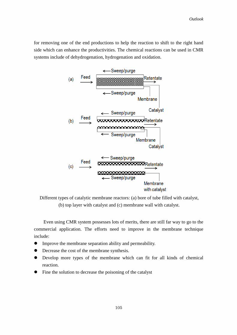
Outlook
105
for removing one of the end productions to help the reaction to shift to the right hand
side which can enhance the productivities. The chemical reactions can be used in CMR
systems include of dehydrogenation, hydrogenation and oxidation.
Even using CMR system possesses lots of merits, there are still far way to go to the
commercial application. The efforts need to improve in the membrane technique
include:
Improve the membrane separation ability and permeability.
Decrease the cost of the membrane synthesis.
Develop more types of the membrane which can fit for all kinds of chemical
reaction.
Fine the solution to decrease the poisoning of the catalyst
Different types of catalytic membrane reactors: (a) bore of tube filled with catalyst,
(b) top layer with catalyst and (c) membrane wall with catalyst.
Acknowledgement
106
Acknowledgements
The research for this thesis was carried out at the Chemical System Engineering
Laboratory, Organics Process Engineering Department, Hokkaido University.
I gratefully acknowledge my supervisors Prof. Takao Masuda, Prof. Teruoki Tago
and Assistant Prof. Yuta Nakasaka for providing me with the opportunity to undertake
PhD Studenties. I highly appreciate their patience and support throughout the research
process, conferences, and publications.
Special thanks go to Hisaki Kondoh for his assistance in both study and daily lives
as foreign student in Japan. I also thank Taichi Taniguchi and Gaku Watanabe for their
guidance at the different area of research. I also wish to thank membrane group
members such as Yuki Satoh, Aya Hirata, Miho Haswgawa and Jihye Choi for their help
and cheerful discussions. I am also grateful to all my colleagues in Chemical System
Engineering Laboratory for their support and friendships.
My warmest thanks go to my family in China and friends for their support and
encouragement to finish my study in Japan.
Study Achievements
107
Study Achievements
Original papers
1. Yaqi Zhang, Yuta Nakasaka, Teruoki Tago, Aya Hirata, Yuki Sato, Takao Masuda:
“Preparation and Optimization of Mordenite Nanocrystal-Layered Membrane for
Dehydration by Pervaporation” Microporous and Mesoporous Materials, Vol. 207,
2015, pp. 39-45
2. Yaqi Zhang, Aya Hirata, Yuta Nakasaka, Teruoki Tago, Taichi Taniguchi, Takao
Masuda: “Effects of crystal morphology, Si/Al ratio and thickness of MTW zeolite
membrane on water/2-propanol separation by pervaporation” Microporous and
Mesoporous Materials, Vol. 222, 2016, pp. 178-184
Conferences
3. ○Yaqi Zhang, Aya Hirata, Yuta Nakasaka, Teruoki Tago, Taichi Taniguchi, Takao
Masuda: “Selective Separation of Water from Water/Organic Mixtures by
Pervaporation using MTW type zeolite membrane” XIth European Congress on
Catalysis, France, September, 2013
4. ○Yaqi Zhang, Yuta Nakasaka, Teruoki Tago, Aya Hirata, Yuki Sato, Takao Masuda:
“Optimization of MOR zeolite membrane preparation for separation of water from
water/organic mixtures by pervaporation” The 6th Asia-Pacific Congress on
Catalysis (APCAT-6), Taiwan, October, 2013
5. ○Yaqi Zhang, Aya Hirata, Yuta Nakasaka, Teruoki Tago, Taichi Taniguchi, Takao
Masuda: “Preparation of MTW type zeolite Membrane for high purification of
organic solution production by pervaporation” The 26th International Symposium
on Chemical Engineering, Korea, December, 2013
6. ○Yaqi Zhang, Yuta Nakasaka, Teruoki Tago, Aya Hirata, Yuki Sato, Takao Masuda:
“Optimization of MOR zeolite membrane preparation for separation of water from
water/organic mixtures by pervaporation” The 4th CSE Summer School Post
ISHHC-16 CRC International Symposium, Japan, August, 2013
7. ○Yaqi Zhang, Aya Hirata, Yuta Nakasaka, Teruoki Tago, Taichi Taniguchi, Takao
Masuda: “Preparation of MTW type zeolite membrane for the dehydration of the
organic solution by pervaporation” The Seventhe Tokyo Cnference on Advanced
Study Achievements
108
Catalytic Science and Technology (TOCAT7), Japan, June, 2014
8. ○Yaqi Zhang, Aya Hirata, Yuta Nakasaka, Teruoki Tago, Takao Masuda: “High
purification of organic solution by pervaporation with MTW type zeolite
membrane” The 3rd Frontier Chemistry Center International Symposium, Japan,
June, 2014
9. ○Yaqi Zhang, Miho Hasegawa, Yuta Nakasaka, Canan Gucuyener, Teruoki Tago,
Jorge Gascon, Freek Kaoteijn, Takao Masuda: “Stnthesis of size-controlled ZIF-8
nanocrystals by addition of nonionic surfactant in water solution”International
Symposium on Zeolite and Microporous Crystals 2015 (ZMPC2015), Japan, July,
2015.
10. ○Yaqi Zhang,平田彩,中坂佑太,多湖輝興,増田隆夫: “含水有機溶液からの高選択的
脱水を可能とするモルデナイトナノクリスタル積層膜の開発” 第 29 回ゼオライト研究
発表会,2013年 7月,北海道
11. ○Yaqi Zhang,中坂佑太,多湖輝興,佐藤由貴,平田彩,増田隆夫: “含水有機溶液からの
高選択的脱水を可能とするモルデナイトナノクリスタル積層膜の開発” 第 29 回ゼオ
ライト研究発表会,2013 年 12 月,宮城
12. ○Yaqi Zhang,平田彩,中坂佑太,多湖輝興,増田隆夫: “MTW型ゼオライト膜によ
水/有機物質共沸混合液からの選択脱水” 化学系学協会北海道支部 2014 年冬季研究
発表会,2014 年 1月,北海道
13. ○Yaqi Zhang,平田彩,中坂佑太,多湖輝興,増田隆夫: “水/2-プロパノール共沸混合
液からの選択脱水を達成する MTW 型ゼオライト膜の開発” 2014 化学工学会第 79 年
会, 2014 年 3月,岐阜
14. 平田彩,Yaqi Zhang,中坂佑太,多湖輝興,増田隆夫: “MTW 型ゼオライト膜による水/2-
プロパノール共沸混合液からの選択脱水” 第 53 回オーロラセミナー,2013 年 7 月,旭
川
15. 平田彩,Yaqi Zhang,中坂佑太,多湖輝興,増田隆夫: “MTW型ゼオライト膜を用いた浸
透気化分離法による水/2-プロパノール共沸混合液からの選択脱水” 化学工学会第45
回秋季大会,2013年9月,岡山
16. 平田彩,Yaqi Zhang,中坂佑太,多湖輝興,増田隆夫:“MTW 型ゼオライト膜による水/
有機物質共沸混合液からの選択脱水” 化学系学協会北海道支部 2014 年冬季研究発表会,
2014年1月,北海道