lta zeolite membranes: current progress and challenges in
TRANSCRIPT

RSC Advances
REVIEW
Ope
n A
cces
s A
rtic
le. P
ublis
hed
on 0
7 Ju
ne 2
017.
Dow
nloa
ded
on 2
/13/
2022
4:4
6:19
PM
. T
his
artic
le is
lice
nsed
und
er a
Cre
ativ
e C
omm
ons
Attr
ibut
ion
3.0
Unp
orte
d L
icen
ce.
View Article OnlineView Journal | View Issue
LTA zeolite mem
Cite this: RSC Adv., 2017, 7, 29520
Received 22nd March 2017Accepted 19th May 2017
DOI: 10.1039/c7ra03341a
rsc.li/rsc-advances
aDepartment of Chemical Engineering, Fac
Teknologi Bandung, Jl. Ganesha 10, Bandu
che.itb.ac.idbResearch Center for Nanosciences and Nano
Jl. Ganesha 10, Bandung – 40132, Indonesi
IbeTndinRsIia
levels, with a career spanning mointerests include membrane prepaand membrane fouling.
29520 | RSC Adv., 2017, 7, 29520–2953
branes: current progress andchallenges in pervaporation
I. G. Wenten, *ab P. T. Dharmawijaya, b P. T. P. Aryanti, c R. R. Mukti bd
and Khoiruddin a
Linde Type A (LTA) zeolite-based membranes have demonstrated excellent selectivity in pervaporation due
to their unique structural framework and interaction with water. The development of LTA zeolite
membranes for commercial application is limited by some parameters, particularly the complexity of the
membrane preparation required to produce reproducible defect-free membranes and the high costs
required for the membrane materials. In addition, the high content of Al in the zeolite framework makes
the LTA zeolite membrane unsuitable for acidic conditions. A number of modification techniques have
been proposed to produce a thin, defect-free, and high permselectivity LTA zeolite membrane with high
reproducibility. Two major approaches are generally used to produce defect-free zeolite membranes, i.e.
modifying either the seeding step or the synthesis process. Since the self-supported zeolite membrane
has low mechanical stability, the LTA zeolite membrane is usually synthesized on an inorganic support to
give better properties. Zeolite membrane costs can be reduced by several methods such as replacing the
support, manufacturing a higher flux zeolite membrane, and fabricating a polymer–zeolite membrane.
One should consider, however, that changing the support can dramatically influence and even reverse
the obtained separation behavior. Despite various techniques used to prepare dense LTA zeolite
membranes, a facile mass production technique with a highly reproducible result remains a significant
challenge. To present a clear background for LTA zeolite and its performances in pervaporation, this
paper includes a brief discussion on the recent trends related to LTA zeolite membranes. Some topics
are discussed, including the features inherent to LTA zeolite, the transport phenomena in zeolite
structures, preparation methods of LTA zeolite membranes, and the challenges associated with
ulty of Industrial Technology, Institut
ng – 40132, Indonesia. E-mail: igw@
technology, Institut Teknologi Bandung,
a
cDepartment of Chemical Engineering, Jenderal Achmad Yani University, Jl. Terusan
Jendral Sudirman, PO Box 148 Cimahi, Jawa Barat, IndonesiadDivision of Inorganic and Physical Chemistry, Faculty of Mathematics and Natural
Sciences, Institut Teknologi Bandung, Jl. Ganesha 10, Bandung – 40132, Indonesia
Gede Wenten received hisachelor's degree in chemicalngineering from Instituteknologi Bandung (ITB) Indo-esia and his MSc and PhDegrees from DTU Denmark. Hes a professor of chemical engi-eering and a member of theesearch Center for Nano-ciences and Nanotechnology,TB. He has extensive experiencen membrane technology, botht industrial and academicre than 20 years. His researchration, membrane applications,
Putu Teguh Dharmawijayareceived his bachelor's degree inchemical engineering fromInstitut Teknologi Bandung(ITB) in 2015. Aerwards, heworked as a research assistantat the Research Center forNanosciences and Nanotech-nology, ITB, under the supervi-sion of Professor Wenten from2015–2016. He is currentlystudying for an MSc in AdvancedChemical Engineering as Indo-
nesia Endowment Fund for Education Awardee at Imperial CollegeLondon.
9 This journal is © The Royal Society of Chemistry 2017

PPf(sm2SnfMie
versitas Jenderal Achmad Yani (Uher current research interests inclmodication.
Rdv2PpUtwhsmm
been an assistant Professor at Insnesia. His research interests involmesoporous, and hierarchically pthe development of characteriztechniques.
This journal is © The Royal Society of C
Review RSC Advances
Ope
n A
cces
s A
rtic
le. P
ublis
hed
on 0
7 Ju
ne 2
017.
Dow
nloa
ded
on 2
/13/
2022
4:4
6:19
PM
. T
his
artic
le is
lice
nsed
und
er a
Cre
ativ
e C
omm
ons
Attr
ibut
ion
3.0
Unp
orte
d L
icen
ce.
View Article Online
preparation. Furthermore, critical issues related to LTA zeolite membranes in pervaporation will be
discussed to develop the topic further.
Introduction
Membrane technology has shown an excellent performance inseparation processes.1–9 Membranes have lower energy andoperational costs and are more scalable than conventionalseparation processes.10–12 They have developed rapidly duringthe last 40 years. During those years, many modications havebeen developed in respect to process conguration and/ormembrane materials.13–23
Pervaporation is a membrane-based separation processwherein the membrane acts as a selective barrier between a feed(liquid phase) and a permeate (vapor phase). The desiredcomponents in the feed pass through the membrane byvaporization. A vacuum is maintained on the permeate side toallow the permeating components to vaporize. Separation by
utu Teta P. Aryanti received herhD in Chemical Engineeringrom Institut Teknologi BandungIndonesia) in 2016 under theupervision of Prof. Wenten. Heraster's degree was received in002 from Institut Teknologiepuluh Nopember (ITS), Indo-esia, and her bachelor's degreerom Institut Teknologi Nasionalalang (ITNMalang), Indonesia,
n 1997. She joined the chemicalngineering department at Uni-NJANI), Indonesia, in 2016 andude membrane preparation and
ino R. Mukti received his PhDegree from Technische Uni-ersitat Munchen (Germany) in007 under the supervision ofrof. J. A. Lercher. He carried outostdoctoral research at Theniversity of Tokyo, (Japan) inhe group of Prof. T. Okubo,orking on the development ofierarchical zeolite and under-tanding the crystallizationechanisms of novel crystalorphologies. Since 2011, he hastitut Teknologi Bandung, Indo-ve the synthesis of microporous,orous crystalline materials andation based on spectroscopy
hemistry 2017
pervaporation is almost independent of the vapor–liquid equi-librium, because the transport depends on the sorption andmobility of the components in the membrane.24 Pervaporationis mainly used for the separation of water from organic liquidsdue to the azeotropic limitations of some mixtures duringconventional distillation processes. Different types ofmembrane materials have been used for pervaporation, such aspolymeric, ceramic, and composite membranes.25
Zeolite has been considered as a promising pervaporationmembrane material due to its uniform and well-dened poresize, high porosity, and ability to operate under extremeconditions.26 As the most frequently produced zeolite type, LTAzeolite is a prominent candidate.27 Due to their high hydro-philicity, LTA zeolite membranes have shown excellent perfor-mances in separations related to polar molecules. In addition,their tunable pores make them sufficiently exible for use inmolecular sieving separation.28
LTA membranes were the rst zeolite membranes to be usedin commercial scale applications.29 In 1999, the rst industrialfacility for ethanol dehydration using NaA zeolite membraneswas established by Mitsui Engineering and Shipbuilding Co.,Japan for solvent dehydrations such as ethanol, IPA, andmethanol.30 In 2011, another ve plants for ethanol dehydration(30 000; 60 000; 80 000; 100 000; and 200 000 L per day) wereconstructed by the German consortium GFT MembraneSystems GmbH Homburg/Saar, which were equipped with four-channel-alumina tubes coated with LTA zeolite membrane (onthe inner wall of the alumina tube).27 Currently, there are over100 industrial facilities based on LTA zeolite membranes.31
There are many reviews discussing zeolite membranes andtheir features.25,29,32–35 Some reviews even focused on specicapplications of zeolite membranes, such as fuel cells,36 gasseparation,12 membrane reactors,37 and some emerging appli-cations.38,39 However, to the best of our knowledge, there is noreview that specically discusses LTA zeolite membranes,although they have many unique features and were the rstcommercially available zeolite membranes. This paper willdiscuss general research trends related to LTA zeolite
Khoiruddin received his bache-lor's degree from UniversitasDiponegoro, Indonesia, and hismaster's degree from InstitutTeknologi Bandung (ITB), Indo-nesia, in chemical engineering.He is currently a PhD student atchemical engineering, ITB,advised by Professor Wenten. Hisresearch focuses on the prepara-tion, characterization, modica-tion, and application ofheterogeneous ion-exchangemembranes.
RSC Adv., 2017, 7, 29520–29539 | 29521

RSC Advances Review
Ope
n A
cces
s A
rtic
le. P
ublis
hed
on 0
7 Ju
ne 2
017.
Dow
nloa
ded
on 2
/13/
2022
4:4
6:19
PM
. T
his
artic
le is
lice
nsed
und
er a
Cre
ativ
e C
omm
ons
Attr
ibut
ion
3.0
Unp
orte
d L
icen
ce.
View Article Online
membranes, including their application in pervaporation,industrial use, preparation, and future potential. Specialattention will be given to the fabrication of LTA zeolitemembranes in order to broaden their use on an industrial scale.
Principles and practice of zeolitemembranes in pervaporation
Pervaporation is a membrane-based process in which a liquid-phase stream is placed in contact with a dense membrane onthe feed side and where permeate is removed as vapor byapplying a vacuum on the permeate side.40 The overall resultsare a vapour permeate and a liquid retentate. Pervaporation canbe classied as vacuum pervaporation and sweep gas pervapo-ration, according to the process used to establish a partialpressure difference41 (Fig. 1). Mostly, vacuum pervaporation isused.
Pervaporation is used to separate a liquidmixture containingtwo or more miscible components that have azeotropic or close-boiling point characteristics. The features of pervaporation arelow temperature and pressure, ability to separate an azeotropicmixture with low energy consumption, without entrainer orcontamination, and independence from vapor–liquid equilib-rium.42 With these advantages, pervaporation can be used asa potential alternative to distillation. The potential applicationsof pervaporation include: (1) dehydration of organic-aqueousmixtures, (2) removal of the organic fraction from an organic-aqueous mixture, and (3) separation of organic–organicmixtures.43,44 Today, pervaporation is widely used in the
Fig. 1 Schematic of pervaporation process. (A) Type of pervaporationand (B) mechanism of pervaporation process.
29522 | RSC Adv., 2017, 7, 29520–29539
dehydration of organic-aqueous mixtures. Furthermore, perva-poration can be a breakthrough technology in organophilicseparation, pervaporation membrane reactors, and bioethanolupgrading.45
Pervaporation is considered to be one of the most useful andpromising methods in the dehydration of organic solvents (e.g.,alcohols, ethers, acids, and ketones) since it has the capabilityto separate a solution beyond the azeotropic limit. The superi-ority of pervaporation is mainly due to its separation principle,which is not based on differences in volatilities, as encounteredin the distillation process, but on solution–diffusion (oradsorption–diffusion in zeolite-based membranes). Traditionaldistillation can only be used to recover pure solvents with theuse of entrainers. Subsequently, an additional separation step isneeded.46 Moreover, products obtained using entrainers cannotbe used for several applications. Pervaporation is also moreenergy efficient compared with distillation. Azeotropic distilla-tion requires 3305 kJ kg�1 ethanol, while pervaporation onlyrequires 423 kJ kg�1 for ethanol dehydration from 95% to99.5%.47
Separation by pervaporation comprises several stepsincluding sorption of components into a membrane phase,permeation or diffusion of components in the membranephase, and evaporation of components on the permeate side. Inparticular, this can be achieved due to the different affinitiesand different diffusion rates of components in the membrane.48
The mechanism is generally explained by using the solution–diffusion model.
Permeate ux and selectivity are the two most importantparameters that are usually used for evaluating pervaporationperformance. The ux and selectivity of the pervaporationprocess have been explained by Shao and Huang49 using solu-tion–diffusion theory as follows. When the liquid feed mixturemakes contact with the membrane, a thermodynamic equilib-rium is reached at the membrane–solution interface. Theconcentrations of a component in the feed solution (Ci,feed) andmembrane (Ci,m) are expressed by:
K ¼ Ci;m
Ci;feed
(1)
where K is the equilibrium coefficient of a component betweenthe membrane and feed interfaces. Pervaporation usesconcentration difference as the driving force.40 In this regard,the ux of a component (Ji) can be expressed using Fick's rstlaw:49
Ji ¼ �D dCi;m
dd(2)
where D is the diffusion coefficient of the component in themembrane and d is a variable of position. Eqn (2) can be rear-ranged by introducing K, thus the ux is expressed as:49
Ji ¼ DKDC
d¼ DK
dDC (3)
This journal is © The Royal Society of Chemistry 2017

Review RSC Advances
Ope
n A
cces
s A
rtic
le. P
ublis
hed
on 0
7 Ju
ne 2
017.
Dow
nloa
ded
on 2
/13/
2022
4:4
6:19
PM
. T
his
artic
le is
lice
nsed
und
er a
Cre
ativ
e C
omm
ons
Attr
ibut
ion
3.0
Unp
orte
d L
icen
ce.
View Article Online
In eqn (3), if the concentration difference is taken as thedriving force, then the permeability of the component (Pi) in themembrane phase is dened as:
P ¼ DK (4)
Meanwhile, the selectivity of the membrane is dened as:
ai;j ¼ Pi
Pj
¼ DiKi
DjKj
(5)
which is known as an ideal separation factor. The separationfactor may also be dened as:
ai;j ¼Yi
�Yj
Xi
�Xj
(6)
where Y and X are the fractions of the component in thepermeate and feed, respectively.
In pervaporation, the separation factor depends on themembrane material, the components in the feed, and alsooperating parameters such as feed temperature and composi-tion as well as permeate pressure.48 To obtain both high ux andselectivity, a suitable membrane should be used. Two strategieswere proposed by Jiang et al.50 to develop a suitable syntheticmembrane for pervaporation. The rst strategy is designingamembrane with desired physicochemical properties, while thesecond is macromolecular engineering of a membrane struc-ture with the desired morphology, which is ultrathin and defect-free. Besides the performance, e.g. ux and selectivity, themembrane characteristics also determine the applicability ofthe pervaporation process. A hydrophilic membrane can beused for permeating water from a water–organic mixture, whilea hydrophobic membrane is used for permeating organiccompounds from the mixture.
The development of zeolite membranes has gained increasinginterest due to their unique properties, such as well-dened poresizes and superior mechanical, thermal, and chemical propertiescompared to polymeric membranes.51–53 With these properties,zeolite membranes are suitable for use in various potential appli-cations, e.g. selective reaction membranes, catalytic membranereactors, gas separation membranes, and pervaporation.53–55 Thehydrophilic nature of zeolite makes it suitable for pervaporationprocesses, especially for solvent dehydration or water removalfrom organic/water mixtures. Zeolite membranes contain twomain types of pores that are involved in pervaporation: zeolitepores and non-zeolite pores. The former are known as intra-crystalline pores while the latter are intercrystalline pores. Thesenames describe the pathways that molecules will follow duringpervaporation. An intracrystalline pathway occurs within onesingle crystal of zeolite, while an intercrystalline pathway existswithin a small channel formed by two adjacent zeolite crystals.56
During pervaporation, both types of pores inuence thetransport process across the membrane with their own mech-anisms.26 Nevertheless, adsorption–diffusion is the primarytransport mechanism and prevails in both zeolite and non-zeolite pores. However, for non-zeolite pores, there are alsoseveral mechanisms that may prevail, such as viscous ow and
This journal is © The Royal Society of Chemistry 2017
Knudsen diffusion. This is true especially when the size of thepermeate is much larger than that of the zeolite pores.29
The adsorption process during pervaporation with a zeolitemembrane is a physical phenomenon. The extent of interactionbetween the adsorbate and adsorbent is proportional to theenergy released during adsorption. Hence, a molecule thatreleases more energy during adsorption will have a strongeradsorption tendency than a molecule with lower adsorptionenergy. This also indicates that adsorption energy is differentfrom one molecule to another and is dependent on severalfactors, such as molecular weight, dipole moment, and molec-ular branching.29 Hence, there will be molecules that have lowand high surface coverages on a zeolite membrane. Comparedto other molecules, the heat of adsorption of water is unusuallyhigh (25–30 kcal mol�1) on zeolite.57 This heat of adsorption isgreatly inuenced by electrostatic forces because zeolites havean ionic structure and water is a polar molecule.47 Moreover, fora specic case where molecules have low surface coverage,surface coverage is inversely proportional to temperature sincea higher temperature will promote desorption. Under theseconditions, surface coverage during adsorption can bedescribed by the equation below.29
qfexp
��DHads
RT
�(7)
Aside from temperature, the surface coverage can also beaffected by the hydrophilicity of the zeolite. Water will havea higher tendency to be adsorbed on a hydrophilic zeolite whileorganic molecules exhibit higher adsorption on hydrophobiczeolite. In this respect, water is preferentially adsorbed ontoa hydrophilic zeolite surface compared with organic molecules.Moreover, this property is observed with both zeolite and non-zeolite pores in zeolite membranes.58 Hence, in the presenceof a sufficient amount of water vapor, permeation of othercomponents in the feed mixture can be signicantly reduceddue to the coverage of the pore surface by water molecules.However, this condition will not occur in the absence of watermolecules, resulting in permeation transport that is governedby non-zeolite pores.
Accompanying adsorption, diffusion occurs because of thegradient in the chemical potential. For zeolite pores, the pre-vailing diffusion is congurational diffusion.29 In this respect,there are several parameters that inuence the diffusion: porediameter, molecular kinetic diameter, temperature, degree ofcoverage, and the presence of other components in the case ofmulticomponent diffusion.29
Using the adsorption–diffusion model as a basis, transportthrough a zeolite membrane can be modeled using theMaxwell–Stefan approach as developed by Pera-Titus and co-workers.56,59 The basic equation for the Maxwell–Stefan modelfor zeolite was given previously by Krishna and Wesselingh:25,60
�Vmi ¼ RTXn
j¼1
qj
�ui � uj
�Ds
ij
þ RTqnþ1
ðui � unþ1ÞDs
i;nþ1
(8)
in which i ¼ 1, 2, ., n.
RSC Adv., 2017, 7, 29520–29539 | 29523

RSC Advances Review
Ope
n A
cces
s A
rtic
le. P
ublis
hed
on 0
7 Ju
ne 2
017.
Dow
nloa
ded
on 2
/13/
2022
4:4
6:19
PM
. T
his
artic
le is
lice
nsed
und
er a
Cre
ativ
e C
omm
ons
Attr
ibut
ion
3.0
Unp
orte
d L
icen
ce.
View Article Online
This is the basic equation used in many transport modelsproposed for permeation across zeolite membranes.56,59–62 Thisequation describes a process where an adsorbed moleculediffuses within a micropore where surface forces are dominant.The molecule will jump from one adsorption site to anotherdriven by the surface chemical potential gradient (le-hand sideof eqn (8)). Both terms on the right-hand side are related tofriction occurring within the micropore. The rst term on theright-hand side reects friction between components i and j,while the second term denotes the friction experienced by anadsorbed molecule (molecule i) from the vacancy site. Theabove equation can then be simplied to the equation below.
� qi
RTVmi ¼
Xn
j¼1
qjNsi � qiN
sj
rp3qsatDsij
þ Nsi
rp3qsatDsij
(9)
in which i ¼ 1, 2, ., n and j s 1.Further simplication of the equation can be made by
ignoring the rst term on the right-hand side (friction occurringbetween molecules). However, this condition only prevails ifthere is only one molecule that passes through the membrane;thus, there will be no friction between the molecule and itscounterparts. In solvent dehydration using an LTA zeolitemembrane, this condition exists when water vapor is the onlymolecule that is transported across the membrane. However,when there is competition to reach a vacant site of the LTAzeolite membrane, this term can no longer be neglected sincemore than one molecule is transported. And, as can be pre-dicted, this is the case where a feed mixture contains water anda polar organic solvent, since both of these will compete foradsorption on the LTA zeolite surface.62
The Maxwell–Stefan eqn (9) above can be simplied to eqn(10). Eqn (10) denotes the linear relationship between the waterux and partial pressure and has been conventionally used byresearchers to model pervaporation transport.62
Jw ¼ Kw
�awP
sw � ywPp
�(10)
Recently, a specic transport mechanism in commerciallyavailable LTA zeolite membranes has been developed usinga zeolite–non-zeolite pore approach.63 This model assumes thatthe LTA zeolite membrane has zeolite pores and very narrowand ne non-zeolite pores and that the membrane surface isdominated by zeolite pores. Furthermore, this model alsoassumes that zeolite crystals within the membrane structure arerandomly arranged. This means that a parallel ow approach,where both zeolite and non-zeolite pores stand side by side andcontribute evenly to permeate transport, can no longer be used.
During dehydration, permeation is begun by adsorption ofwater molecules into zeolite pores. At the beginning, the non-zeolite pores are not involved in water uptake due to thenegligible available area of non-zeolite pores compared withzeolite pores and also because these pores contain condensatethat hinders water molecules from passing through. Aerwards,water molecules will move from zeolite pores to non-zeolitepores, where capillary condensation occurs due to the smallradius of the non-zeolite pores. This condensation
29524 | RSC Adv., 2017, 7, 29520–29539
phenomenon is responsible for lling up non-zeolite pores withwater, resulting in inhibition of water uptake by non-zeolitepores from the feed side. Finally, upon the application ofa vacuum at the permeate side, the condensate will evaporateand be transported through the support layer in which Knudsendiffusion governs the process.
Mass transfer within intercrystalline defects will be differentfrom that within intracrystalline defects. Mass transfer acrossthe membrane through intercrystalline defects is expected tooccur by three main mechanisms: (1) Knudsen diffusion, (2)pressure-driven viscous ux, and (3) surface diffusion ofadsorbed molecules by skating along the pore walls.61 However,viscous ux and Knudsen diffusion usually dominate thetransfer mechanism because of large intercrystalline defectpores. Eqn (11) describes an intercrystalline ux that accountsfor both viscous ux (rst term on the right-hand of the equa-tion) and Knudsen ux (second term on the right-hand of theequation).59 For practical purposes, empirical eqn (12) has beenderived from eqn (11) to infer the intercrystalline porosity giventhe water/ethanol selectivity of a target zeolite LTA membrane,and this was proven to t the experimental data for separationfactors up to 1000.59
Ninter ¼ 1
lZA
"DL
RT
�Po � PC
L
�þXNi¼1
DKn;i
RT
�PC
v;i � Pv;i
�#(11)
3inter ¼ exp�ð0:83� 0:08Þln�aw=E
�� ð10:5� 0:3Þ (12)
Fabrication of LTA zeolite membranes
Various types of zeolite membranes have been prepared andreported in the literature, such as LTA, FAU, MOR, FER, MEL,and AFI.33 Differences in the aluminium to silica ratios give thezeolite membranes unique structures and pore sizes. Zeolitecan be dened as hydrated; the crystalline structure of tectoa-luminosilicate is constructed from TO4 (T ¼ tetrahedral atoms)with an oxygen atom that is shared between two adjacenttetrahedral atoms.64 In addition, zeolite also contains a cationin its structure to balance its negatively charged aluminosilicateframework. The cations can come from either alkali metals oralkaline-earth metals.64 Thus, the chemical composition ofa zeolite can be represented as:
Ay/mm + [(SiO2)x(AlO2–)y]zH2O
where A is a cation with charge m and (x + y) represents thenumber of tetrahedrons per crystallographic unit cell.65 For LTAzeolite, a common cation is Na+ with Si/Al ¼ 1; hence, it hasa general formula of [Na12(Al12Si12O48)$27H2O].
LTA zeolite exhibits typical single-crystal cubic shapes withsmooth surfaces and angular edges.66 It usually has sizes ofa few mm depending on the synthesis conditions. Usually, LTAzeolite is prepared in the Na+ form and the structure showsa three-dimensional pore network that resembles a sodalitecage, a building block similar to that of FAU and EMT zeolite.5–65
The tetrahedra are linked to form cages connected by pore
This journal is © The Royal Society of Chemistry 2017

Review RSC Advances
Ope
n A
cces
s A
rtic
le. P
ublis
hed
on 0
7 Ju
ne 2
017.
Dow
nloa
ded
on 2
/13/
2022
4:4
6:19
PM
. T
his
artic
le is
lice
nsed
und
er a
Cre
ativ
e C
omm
ons
Attr
ibut
ion
3.0
Unp
orte
d L
icen
ce.
View Article Online
openings of dened sizes. This connection results in threedifferent cages: d4r, sodalite cage (b-cage), and LTA cage (a-cage). The negative charge on the lattice is neutralized by thepositive charges of cations located within the material's pores.In the basic zeolites, these are usually univalent and bivalentmetals or a combination of these. The metal cations may bereplaced by acidic protons via ion-exchange to ammonium andsubsequent calcination.67 Metal cation replacement will modifythe pore opening from 0.4 nm in the normal Na form to 5 nm or3 nm by ion exchange with aqueous solutions of calcium orpotassium salts, respectively.29,68,69 The typical morphology ofzeolite LTA membrane is shown in Fig. 2.
The pore diameter of LTA zeolite is dened by an eight-membered oxygen ring with diameters between 0.23 and0.42 nm.70 This size is close to that of a water molecule, whichhas a molecular diameter of about 0.275 nm.71 The LTA zeoliteform has eight sodium ions located inside a-cages and four ionslocated in b-cages. LTA zeolite has a void volume fraction of0.47, with an Si/Al ratio of 1.0. This high aluminum contentmakes it hydrophilic. Aluminum is trivalent so it requirescations to balance its charge when it is in the zeolite frameworkin place of Si. The localized electrostatic poles between thenegatively charged framework and positively charged cationsstrongly attract highly polar molecules, resulting in a hydro-philic structure.29
Although the physical and chemical properties of zeoliteslargely depend on their structures, the morphology and sizedistributions of zeolite crystals also have a signicant effect ontheir properties and applications.73 In general, LTA zeolites areextremely hydrophilic with a crystal pore size close to the size ofa water molecule. Thus, LTA zeolite membranes are widelystudied as pervaporative membranes for the dehydration ofalcohol or other solvents.74
Fig. 2 Typical morphology of LTA zeolite crystal monolayer (magni-fication �1200). Reprinted with permission from A. Kulak, Y. J. Lee, Y.S. Park and K. B. Yoon, Orientation-Controlled Monolayer Assembly ofZeolite Crystals on Glass and Mica by Covalent Linkage of Surface--Bound Epoxide and Amine Groups, Angew. Chem., 2000, 112, 980–983. Copyright (2000) John Wiley and Sons.72
This journal is © The Royal Society of Chemistry 2017
Primary growth method
Generally, LTA zeolite membranes are prepared by hydro-thermal synthesis onto a porous support. Based on the growthof LTA crystals, the techniques can be classied as primary orsecondary growth methods (Fig. 3). In primary growth,a support is coated with synthesis solution and undergoesdirect hydrothermal synthesis. Meanwhile, in secondarygrowth, a support is seeded using zeolite crystals prior tohydrothermal synthesis. Several zeolite membranes, theirpreparation methods, and pervaporation performances are lis-ted in Tables 1 and 2.
The preparation of LTA zeolite membranes using primarygrowth methods has been reported in the literature. Severaltechniques have been developed for hydrothermal synthesis,such as batch, continuous, or semi-continuous mode. Basaket al. reported the synthesis of an LTA zeolite membrane on theinner wall of a porous alumina support by a low temperature (65�C) primary crystallization method in batch mode.75 Thesupport is dipped in synthesis solution and heated for a giventime. The support is then placed in a new synthesis solution inan inverted position and heated for the same time. The resultsof the study showed that the crystallization time affects thethickness of the membrane, with thicknesses of 10, 20, and 30mm for growth times of 6 h, 12 h, and 24 h, respectively. Theyfound that the membrane with the fewest defects was obtainedaer 12 h (6 h + 6 h) crystallization time. With a higher crys-tallization time, defects were generated because the zeoliteformed a thicker layer.
Aguado et al. reported the preparation of LTA zeolitemembranes on macroporous a-alumina supports that had beenpreviously modied.76 Prior to hydrothermal synthesis, thesupport was coated with three types of organic modier, i.e.poly(diallyldimethylammonium chloride) or PDDA, poly-ethylene glycol (PEG), and glucose. The support was immersedin organic solution and calcinated (400 �C for 3 h). This calci-nation is required to remove the sacricial organic phase. Themodied support is then placed in an autoclave containingsolution. During the hydrothermal synthesis, the autoclave isrotated (60 rpm) to prevent the incorporation of suspendedcrystals into the LTA zeolite layer. They found that the modierimproves the continuity of the LTA layer and the crystal
Fig. 3 Schematic of LTA zeolite membrane preparation methods.
RSC Adv., 2017, 7, 29520–29539 | 29525

Tab
le1
LTAze
olitemembranespreparedbyprimarygrowth
methodsan
dtheirperform
ance
sin
solventdehyd
rationa
No.
Supp
ortmaterial
Hyd
rothermal
synthesis
Zeolite
thickn
ess
(mm)
Pervap
oration
Ref.
Reactor
T(�C);time(h)
Al 2O3:S
iO2:N
a 2O:H
2O
Feed
mixture
T(�C)
Sepa
ration
factor
Flux
(kgm
�2h�1)
1.a-Aluminatube
Batch
60;2
41:5
:50:1
000
2EtO
H/water
(90%
)75
5086
3.94
772.
a-Aluminatube
Batch
;AC;A
+MH
A:5
0;7;
MH:
90;2
5min
1:5
:50:1
000
5EtO
H/water
(90%
)70
>1000
00.64
80
3.a-Aluminatube
Batch
;MH
+CH
MH:2
5min,
CH:9
0;4h
1:5
:50:1
000
10IPA/water
(95%
)70
>1000
01.44
81
4.a-Aluminatube
Con
tinuo
usow
80;8
12:5
3:5
03:1
000
05
IPA/water
(65%
)90
4117
795.
a-Aluminatube
Vacuu
m-assisted;A
C90
1:5
:50:1
000
14IPA/water
(95%
)70
5289
1.12
746.
a-Aluminatube
Batch
;AC;two-cycles
65;6
+6
1:5
:6:1
000
20EtO
H/water
(90%
)75
42�1
757.
UV-irradiatedrutile/
stainless
steel(at)
Batch
80;4
1:4
.4:4
1.9:8
33.3
3.4
EtO
H/water
(95%
)45
5400
00.86
78
8.Ceram
esh(zirconia
sheeton
Ni/Cralloymesh)
Batch
50–90;
2–48
1:5
:55.12
:104
.66
NA
EtO
H/water
(90%
)70
8500
0.82
105
aAC–au
toclave;
A+MH
–ag
ingan
dmicrowaveheating;
CH
–convention
alheating;
EtO
H–ethan
ol;IPA
–isop
ropy
lalcohol;N
A–not
available.
29526 | RSC Adv., 2017, 7, 29520–29539
RSC Advances Review
Ope
n A
cces
s A
rtic
le. P
ublis
hed
on 0
7 Ju
ne 2
017.
Dow
nloa
ded
on 2
/13/
2022
4:4
6:19
PM
. T
his
artic
le is
lice
nsed
und
er a
Cre
ativ
e C
omm
ons
Attr
ibut
ion
3.0
Unp
orte
d L
icen
ce.
View Article Online
intergrowth. The positive support provided by the PDDA layer isexpected to improve the adhesion between zeolite particles andthe support. This proposed method provides advantages suchas simple pretreatment, elimination of pre-seeding steps, andbetter layer formation.
The formation of a continuous and defect-free zeolite layeron a coarse macroporous support is quite challenging. Li et al.77
used a linker, 3-aminopropyltriethoxysilane (APTES) function-alized Al2O3, to improve the link between the zeolite layer andthe macroporous support. The use of a linker was aimed atproviding heterogeneous sites for zeolite crystals on the supportsurface. First, a larger size of APTES-Al2O3 (1–1.5 mm) wasdeposited on the surface of the support. A smaller size (0.4 mm)was deposited later. The modied support (coated) thenunderwent hydrothermal synthesis for 24 h at 60 �C. By usingthis linker, a thin (2 mm) and compact LTA zeolite layer wasformed. This strategy is potentially useful for the preparation ofa thin and defect-free zeolite layer on a macroporous support.
To obtain a better interaction between the synthesis solutionand the support, Van den Berg et al. used UV irradiation tomodify a titania/stainless steel support before hydrothermalsynthesis.78 They found that UV-irradiated titania/stainless steelhas higher hydrophilicity. Consequently, the interactionbetween the synthesis gel and the support was improved andthe number of nuclei on the support was increased. Thus,a high-quality membrane was produced. The membrane hasa selectivity of up to 54 000 and a ux of 0.86 kg (m2 h)�1 whentested for pervaporation of an ethanol/water mixture. However,the membrane was sensitive to defect formation.
Reactant depletion occurs during the hydrothermalsynthesis, which could reduce nucleation and crystal growthduring this phase. To solve this problem, Aguado et al. intro-duced a continuous synthesis system.79 In continuous ow, thesynthesis solution is continuously recirculated through theinner wall of an asymmetric alumina tubular support. Thesupport was placed in an autoclave for in situ hydrothermalsynthesis (crystallization). A laminar ow is ensured witha Reynolds number of 1–55 for ow rates of 0.10–5.00 mLmin�1. This ow regime is expected to produce a homogeneousdeposition of synthesis solution. The advantages of this methodare that depletion of nutrients in the synthesis solution can beavoided, the composition of the reactants can be effectivelycontrolled, and scale-up of the procedure is more feasible.Huang et al. investigated a vacuum-assisted technique for thehydrothermal synthesis process.74 Their results showed that thenegative effect of the gravitational force during solution coatingcan be reduced by a vacuum-assisted technique. This positivelyimpacts the formation of the zeolite layer on the support. Theentire surface of the support is coated by the zeolite particles;thus, a homogeneous layer is formed. Furthermore, the rate ofcoating can be decreased due to continuous transportation ofthe crystal from the suspension. In addition, the homogeneouslayer facilitates the formation of a dense, defect-free, anduniform LTA zeolite membrane.
Generally, hydrothermal synthesis is conducted in an auto-clave and uses conventional heating. Li et al. reported a prepa-ration method called “in situ aging—microwave synthesis” for
This journal is © The Royal Society of Chemistry 2017
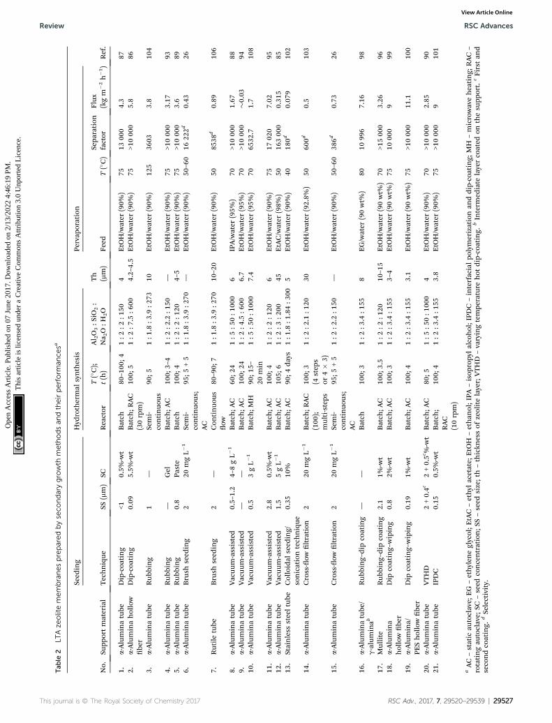
Tab
le2
LTAze
olitemembranespreparedbyseco
ndarygrowth
methodsan
dtheirperform
ance
sa
No.
Supp
ortmaterial
Seed
ing
Hyd
rothermal
synthesis
Th
(mm)
Pervap
oration
Ref.
Technique
SS(mm)
SCReactor
T(�C);
t(h)
Al 2O3:S
iO2:
Na 2O:H
2O
Feed
T(�C)
Sepa
ration
factor
Flux
(kgm
�2h�1)
1.a-Aluminatube
Dip-coa
ting
<10.5%
-wt
Batch
80–100
;41:2
:2:1
504
EtO
H/water
(90%
)75
1300
04.3
872.
a-Aluminahollow
be
rDip-coa
ting
0.09
5.5%
-wt
Batch
;RAC
(30rpm)
100;
51:2
:7.5
:600
4.2–4.5
EtO
H/water
(90%
)75
>1000
05.8
86
3.a-Aluminatube
Rub
bing
1—
Semi-
continuo
us90
;51:1
.8:3
.9:2
7310
EtO
H/water
(90%
)12
536
033.8
104
4.a-Aluminatube
Rub
bing
—Gel
Batch
;AC
100;
3–4
1:2
:2.2
:150
—EtO
H/water
(90%
)75
>1000
03.17
935.
a-Aluminatube
Rub
bing
0.8
Paste
Batch
100;
41:2
:2:1
204–5
EtO
H/water
(90%
)75
>1000
03.6
896.
a-Aluminatube
Brush
seed
ing
220
mgL�
1Semi-
continuo
us;
AC
95;5
+5
1:1
.8:3
.9:2
70—
EtO
H/water
(90%
)50
–60
1622
2d0.43
26
7.Rutile
tube
Brush
seed
ing
2—
Con
tinuo
usow
80–90;
71:1
.8:3
.9:2
7010
–20
EtO
H/water
(90%
)50
8538
d0.89
106
8.a-Aluminatube
Vacuum
-assisted
0.5–1.2
4–8gL�
1Batch
;AC
60;2
41:5
:50:1
000
6IPA/water
(95%
)70
>1000
01.67
889.
a-Aluminatube
Vacuu
m-assisted
——
Batch
;AC
100;
241:2
:4.5
:600
6.7
EtO
H/water
(95%
)70
>1000
0�0
.03
9410
.a-Aluminatube
Vacuum
-assisted
0.5
3gL�
1Batch
;MH
90;1
5–20
min
1:5
:50:1
000
7.4
EtO
H/water
(95%
)70
6532
.71.7
108
11.
a-Aluminatube
Vacuu
m-assisted
2.8
0.5%
-wt
Batch
;AC
100;
41:2
:2:1
206
EtO
H/water
(90%
)75
1702
07.02
9512
.a-Aluminatube
Vacuum
-assisted
1.5
5gL�
1Batch
;AC
105;
61:2
:3:2
0045
EtAC/water
(98%
)50
16300
00.31
585
13.
Stainless
steeltube
Colloidal
seed
ing/
sonicationtech
nique
0.35
10%
Batch
;AC
90;4
days
1:1
.8:1
.84:3
005
EtO
H/water
(90%
)40
180d
0.07
910
2
14.
a-Aluminatube
Cross-ow
ltration
220
mgL�
1Batch
;RAC
(100
);multi-steps
100;
3(4
step
sor
4�
3)
1:2
:2.1
:120
30EtO
H/water
(92.8%
)50
600d
0.5
103
15.
a-Aluminatube
Cross-ow
ltration
220
mgL�
1Semi-
continuo
us;
AC
95;5
+5
1:2
:2.2
:150
—EtO
H/water
(90%
)50
–60
386d
0.73
26
16.
a-Aluminatube
/g-aluminab
Rub
bing–dipcoating
——
Batch
100;
31:2
:3.4
:155
8EG/water
(90wt%
)80
1099
67.16
98
17.
Mullite
Rub
bing–dip
coating
2.1
1%-wt
Batch
;AC
100;
3.5
1:2
:2:1
2010
–15
EtO
H/water
(90wt%
)70
>1500
03.26
9618
.a-Alumina
hollowbe
rDip
coating–wiping
0.8
2%-wt
Batch
;AC
100;
31:2
:3.4
:155
3–4
EtO
H/water
(90wt%
)75
1000
09
99
19.
a-Alumina/
PEShollowbe
rDip
coating–wiping
0.19
1%-wt
Batch
;AC
100;
41:2
:3.4
:155
3.1
EtO
H/water
(90wt%
)75
>1000
011
.110
0
20.
a-Aluminatube
VTHD
2+0.4c
2+0.5c%-wt
Batch
;AC
80;5
1:5
:50:1
000
4EtO
H/water
(90%
)70
>1000
02.85
9021
.a-Aluminatube
IPDC
0.15
0.5%
-wt
Batch
;RAC
(10rpm)
100;
41:2
:3.4
:155
3.8
EtO
H/water
(90%
)75
>1000
09
101
aAC–static
autoclave;
EG
–ethylen
eglycol;EtAC–ethyl
acetate;
EtO
H–ethan
ol;IPA
–isop
ropy
lalcohol;IPD
C–interfacialpo
lymerizationan
ddip-coating;
MH
–microwaveheating;
RAC–
rotatingau
toclave;
SC–seed
concentration;S
S–seed
size;th
–thickn
essof
zeolitelayer;VTHD
–varyingtempe
rature
hot
dip-coating.
bInterm
ediate
layercoated
onthesu
pport.
cFirstan
dsecondcoating.
dSelectivity.
This journal is © The Royal Society of Chemistry 2017 RSC Adv., 2017, 7, 29520–29539 | 29527
Review RSC Advances
Ope
n A
cces
s A
rtic
le. P
ublis
hed
on 0
7 Ju
ne 2
017.
Dow
nloa
ded
on 2
/13/
2022
4:4
6:19
PM
. T
his
artic
le is
lice
nsed
und
er a
Cre
ativ
e C
omm
ons
Attr
ibut
ion
3.0
Unp
orte
d L
icen
ce.
View Article Online
RSC Advances Review
Ope
n A
cces
s A
rtic
le. P
ublis
hed
on 0
7 Ju
ne 2
017.
Dow
nloa
ded
on 2
/13/
2022
4:4
6:19
PM
. T
his
artic
le is
lice
nsed
und
er a
Cre
ativ
e C
omm
ons
Attr
ibut
ion
3.0
Unp
orte
d L
icen
ce.
View Article Online
the preparation of an LTA zeolite membrane on an a-aluminasupport.80 Basically, this method is similar to the primarygrowth method. Before crystallization or thermal synthesisusing microwave heating, the support containing the precursoris aged using conventional heating, which is known as in situaging. The aim of this in situ aging was to adjust the synthesismixture and form germ nuclei. Meanwhile, microwave heatingis used for nucleation and crystal growth on the support. Theresults of this study indicated that in situ aging is necessary forprimary growth using microwave heating. A high-quality LTAzeolite membrane was successfully prepared by this method.Microwave heating could increase the crystallization rate andproduce ne crystals.
Huang and Yang investigated the effect of heating duringhydrothermal synthesis on a zeolite structure and the perfor-mance of the zeolite membrane.81 They compared conventional,microwave, and combined microwave/conventional heating inthe preparation of an LTA zeolite membrane using a porous a-Al2O3 tube as the support. They found that uniform and smallzeolite particles (2–3 mm) were formed when using only micro-wave heating (90 �C; 25 min). However, the membrane or zeolitelayer was not continuous. When the membrane was preparedusing only conventional heating (90 �C; 4 h), other types ofcrystals were formed and the crystal size was not uniform. Inaddition, the growth of the zeolite crystals was less ordered,while the surface of the membrane was very rough and loose.The membrane prepared by combining microwave heating andconventional heating had a better structure with uniform andcompact LTA zeolite crystals. The zeolite layer was continuouswith no intercrystalline gaps, highly intergrown, and verysmooth. Microwave heating produces abundant nuclei, whichleads to the formation of a uniform, pure, and dense zeolitemembrane in the conventional heating process. The resultsshowed that the separation factors (awater/isopropanol) of themembranes were as follows: combined heating (10 000) >conventional heating (171) > microwave heating (28.5). Mean-while, the uxes of the membranes (in kg m�2 h�1) were asfollows: microwave (3.2) > conventional (1.6) > combined heat-ing (1.4).
An interesting synthesis strategy has been developed byHuang and Caro for the preparation of LTA zeolite membranes.In the strategy, linkers were used to functionalize the supportbefore hydrothermal synthesis.82–84 For example, a positivelycharged polymer, poly(diallyldimethylammonium chloride),was used as a covalent linker for the preparation of an LTAzeolite membrane on an a-Al2O3 support.82 Functionalization ofthe support was conducted via an adsorption process (at 60 �Cfor 24 h). Aer adsorption, the support underwent a hydro-thermal synthesis process. The results showed that an orientedand uniform layer of LTA zeolite could be produced. In thiscase, the cationic layer facilitated homogeneous migration ofLTA zeolite particles during the hydrothermal synthesis due toelectrostatic interaction between the cationic polymer andzeolite particles. In another study, diisocyanates were used ascovalent linkers to modify porous and non-porous supportssuch as an asymmetric porous a-Al2O3 disk, a non-porous glassplate, and non-porous stainless steel.83 Urethane bonds were
29528 | RSC Adv., 2017, 7, 29520–29539
formed on the supports as the products of reaction betweenisocyanate groups and surface hydroxyls. Like the cationicpolymer in the previous study, the covalent linker helped toanchor the zeolite particles on the support surface duringhydrothermal synthesis. A uniform and defect-free LTA zeolitemembrane could thus be prepared. Covalent bonding was alsoachieved by treatment with 3-chloropropyltrimethoxysilane(CPTMS),84 which was deposited on the supports (0.2 mM in 10mL toluene at 100 �C for 1 h, under argon). The modiedsupports were then used for preparation of the LTA zeolite layer.As in previous studies, the prepared LTA zeolite membrane wasthin, dense, and defect-free. This strategy is potentially suitablefor the preparation of defect-free LTA zeolite membraneswithout seeding.
Secondary growth method
The primary growth method is simpler than the secondarygrowth method because seeding is unnecessary. However,random crystallization resulting in an inhomogeneous layer isthe main drawback, which has made this method less popular.The secondary growth method is considered as the most effec-tive method for the preparation of defect-free zeolitemembrane. Numerous studies have been reported on thepreparation of LTA zeolite membranes using this method. Inthe secondary growth method, zeolite crystals are seeded on thesupport prior to hydrothermal synthesis. The properties of thecrystal seeds, such as crystal size, thickness, density, andcontinuity of the seed layer, are crucial parameters that affectthe separation properties of as-synthesized LTA zeolitemembranes.76 The support should be homogeneously coveredwith a seed layer to achieve a homogeneous, continuous, anddefect-free zeolite membrane. Various seeding techniques havebeen used in the preparation of zeolite membrane, includingdip-coating, rubbing, cross-ow ltration of a suspension, andcombined techniques. In hydrothermal synthesis, the seeds actas nuclei that provide sites for zeolite growth. In a seededsupport, crystal nucleation and growth are separated; thus,membrane formation can be effectively controlled.74,85 Seedingprovides some advantages; for example, the crystallization timecan be reduced, crystal growth is ensured on the support ratherthan in the solution, and transformation of nuclei into othertypes of crystal is avoided.74,85
LTA zeolite membranes are usually synthesized on the inneror outer wall of a tubular support (Fig. 2). Synthesis of a zeolitelayer on the inner wall of the support is attractive because thelayer can be protected from mechanical damage.86
Dip-coating is a simple seeding technique where a support isdipped into a seed suspension before the hydrothermalsynthesis process.58,87 The main drawback of dip-coating is thatthe seed cannot closely attach to the support surface and thecolloidal suspension easily dribbles when the support is with-drawn.88 Therefore, it is difficult to obtain a uniform andcontinuous seeding layer. This reduced the reproducibility ofthe dip-coating technique.89
Li and co-workers used a varying temperature hot dip-coating seeding technique (VTHD) for the synthesis of an LTA
This journal is © The Royal Society of Chemistry 2017

Review RSC Advances
Ope
n A
cces
s A
rtic
le. P
ublis
hed
on 0
7 Ju
ne 2
017.
Dow
nloa
ded
on 2
/13/
2022
4:4
6:19
PM
. T
his
artic
le is
lice
nsed
und
er a
Cre
ativ
e C
omm
ons
Attr
ibut
ion
3.0
Unp
orte
d L
icen
ce.
View Article Online
zeolite membrane on a coarse macroporous support.90 VTHDcomprises three steps, i.e. (1) seeds are dip-coated on thesupport at a higher temperature; (2) the seeded support isrubbed carefully to remove excess seeds that are loosely packedon the surface; and (3) the support is dip-coated in a seedsuspension at a lower temperature. VTHD is reported as a ex-ible and effective method for controlling the seed concentra-tion, seeding temperature, and seed size. This method makes itpossible to prepare a dense, thin, and defect-free LTA zeolitemembrane on a coarse macroporous support by using seedswith different sizes. Larger seeds were used as ller to reducethe pore size of the support while smaller seeds were used asnuclei. This method showed relatively high reproducibility(70%). This technique has also been used to prepare MFI91 andT zeolite membranes.92
In rub-coating, zeolite crystals or seeds are directly coated ona support surface by rubbing the seeds. Basak et al. used pol-y(ethyleneimine) or PEI to modify an a-alumina support prior toseeding. Seeds are rubbed onto the inner wall of the modiedsupport using a glass rod.75 The seed support is then placed ordipped in synthesis solution and heated at 65 �C for differentcrystallization times (i.e. 6 h, 12 h, and 24 h). The total crys-tallization time comprises two crystallization steps. The rst isused for crystallization where the support is in a top-side downposition, while the second is used for an inverted position. Theresults showed that the PEI coating yielded a good qualitymembrane with a lower crystallization time (6 h). The PEIcoating increased the thickness of the membrane layer. As thecrystallization time was longer, the membrane was thicker. Thethicker layer is more prone to defect formation due to increasedstrain. However, the crystal is easily washed down when thecoated support is immersed in the synthesis solution.88
Wang et al. prepared an LTA zeolite membrane by usinga rub-coating method for seeding a paste containing zeoliteseeds.89 They also used a binding agent derived from seedparticles in a hydrogel form to ll the large holes and producea smooth seeded surface. This method can also prevent seedparticles from intruding into the pores of the support. Deposi-tion of seed paste is potentially useful for seeding a support withlarge pore sizes. Therefore, a cheap, symmetric, and defect-freeLTA zeolite membrane can be prepared on a support with largepores. Ma et al. used a wetting–rubbing method to coat an a-alumina support with a seed hydrogel.93 The hydrogel hasa similar composition to the synthesis solution (secondarygrowth). The hydrogel easily formed a uniform coating. LTAmembranes with separation factors of up to 10 000 can besynthesized.
Vacuum-assisted seeding has been reported by severalresearchers to improve the deposition of seeds on a support. AnLTA zeolite membrane was prepared by Huang et al. usinga vacuum-assisted ltration process for seeding.88 A support isimmersed in a suspension containing seeds and is connected toa vacuum pump. During vacuum ltration, water ows throughthe support pores and the zeolite crystals are transported andcoated on the support surface. This technique can be used tocoat the support surface with a smooth and uniform layer ofzeolite seeds. Aer seeding, the coated support underwent
This journal is © The Royal Society of Chemistry 2017
hydrothermal synthesis. It was reported that under theoptimum conditions (seed size: 500–1200 nm; seed concentra-tion: 4–8 g L�1; vacuum pressure: 0.010–0.025 MPa; coatingtime: 45–180 s), a high-quality LTA zeolite membrane wassuccessfully formed. The membrane showed a separation factorof >10 000 and a ux of 1.67 kg m�2 h�1 in the pervaporation ofisopropanol/water (95% at 70 �C). Cho et al. prepared an LTAzeolite membrane using vacuum-assisted ltration for seedingwith zeolite nanoseeds.94 Membranes with narrow non-zeoliticpores were produced. However, an insignicant water ux inthe zeolitic pores was observed. In vacuum-assisted seeding, thethickness of the seed layer is tunable depending on the seedsuspension concentration, coating time, and vacuum degree.95
Moheb Shahrestani et al. synthesized an LTA zeolite membranefor pervaporation of an acetate/water mixture by a vacuum-assisted technique for seeding micron-sized zeolite powder.85
They reported that by aging the synthesis gel at room temper-ature for 48 h prior to hydrothermal treatment, a high purityLTA zeolite can be effectively synthesized. Prolonging the agingtime produced smaller particles and an impure zeolite phase. Inaddition, the suspension residence time (seeding time) andconcentration were shown to have a signicant effect on theformation of the seed layer. The most stable and uniform layerwas obtained with 90 s and 5 g L�1 seeding time and seedconcentration, respectively. Despite its ability to preparea smooth zeolite layer, the vacuum-assisted seeding techniqueneeds auxiliary equipment; thus, it is inconvenient to operate inlarge-scale production.96
Beside the above-mentioned techniques, several combinedtechniques have been introduced for seeding.97 These were usedto solve the problems associated with simpler techniques suchas dip-coating and rubbing. Dip-coating requires a support witha very smooth and uniform surface to avoid defect formation.However, commercial supports contain pin-holes and dents.With rubbing, it is difficult to achieve a uniform coverage ofseeds on the support surface. Liu et al. studied the inuence ofseeding techniques on the preparation of an LTA zeolitemembrane on a tubular mullite support.96 Three seeding tech-niques, i.e. dip-coating, rubbing, and combined rubbing anddip-coating, were used to coat mullite with LTA seeds (2.1 mm).They found that the dip-coating technique produced well-distributed seeds on a at area of the support surface butpoor coverage on dents and pinholes. On the other hand,rubbing introduced seeds into the dents and pinholes but gaveinhomogeneous coverage on the at area. Meanwhile, thecombined seeding technique could provide a better seed layercompared to the two separate techniques. A uniform distribu-tion of seed could thus be formed.
An LTA zeolite membrane was prepared by Jafari et al. ona modied a-alumina macroporous support using a rubbing–dip coating seeding technique.98 Zeolite nanoseeds wereprepared using an organic structure-directing agent, tetrame-thylammonium hydroxide (TMAOH), in a hydrothermal treat-ment. Prior to seeding, an a-alumina support was modied withg-alumina. The g-alumina with denser pores was used as anintermediate layer. The g-alumina layers were coated by dip-coating of a-alumina supports in boehmite sols. Due to its
RSC Adv., 2017, 7, 29520–29539 | 29529

RSC Advances Review
Ope
n A
cces
s A
rtic
le. P
ublis
hed
on 0
7 Ju
ne 2
017.
Dow
nloa
ded
on 2
/13/
2022
4:4
6:19
PM
. T
his
artic
le is
lice
nsed
und
er a
Cre
ativ
e C
omm
ons
Attr
ibut
ion
3.0
Unp
orte
d L
icen
ce.
View Article Online
denser pores, this intermediate layer could avoid penetration ofnanoseeds; thus, a smooth and thin zeolite layer could be ob-tained. A combined rubbing and dip-coating technique wasused for seeding. In this technique, the seeds were rubbed onthe support surface. Aerwards, the support was dipped intoa seed suspension. The results of the study indicated that anultra-thin layer of LTA zeolite could be synthesized. The thick-ness of the zeolite layer was less than 8 mm. The zeolitemembrane was then tested for pervaporation of an ethyleneglycol/water mixture. The LTA membrane showed an excellentseparation factor (10 996) with a relatively high permeation ux(7.16 kg m�2 h�1).
Wang et al. used a dip coating–wiping technique for thepreparation of an LTA zeolite membrane.99 Aer a support isdipped into the LTA zeolite suspension, it is wiped. In wiping,two ngers of one hand in a Latex glove held the support next tothe joint of the support and the Teon while anther handrotated and pulled the Teon tube through the two ngerstowards the end of the support. They reported that a high-quality LTA zeolite membrane was synthesized. Wiping resul-ted in a much smaller amount of seeds on the support, buta dense membrane was produced. The LTA zeolite membraneexhibited an excellent separation performance (>10 000), indi-cating that the amount of seeds is not the critical factor forpreparing a high-quality membrane. A dip coating–wipingtechnique was also used by Shao et al. for the preparation of anLTA zeolite membrane on asymmetric Al2O3 home-made hollowbers with different macrostructures.100 LTA zeolite membraneswith different thicknesses were made by varying the crystalli-zation time and the number of synthesis cycles. The studyindicated that the pervaporation ux was proportional to theporosity of the support. They also recommended developingand improving the support properties to obtain a high-performance zeolite membrane with good mechanicalstrength. A dip coating–wiping technique was also reported byYan et al., using ball-milled microcrystal seeds.66
Cao et al. introduced a novel seeding technique combininginterfacial polymerization (IP) and a dip-coating technique forseeding.101 This technique was used to coat nanocrystals (150nm) onto a micrometer-sized a-Al2O3 hollow ber support. Inthis technique, the seed suspension dissolved in piperazinewith a monomer concentration of 1 � 10�2 g mL�1 was used asan aqueous phase and a solution of trimesoyl chloride in n-hexane at 1.5 � 10�3 g mL�1 was the organic phase. First, thesupport was dipped into an aqueous phase solution. The coatedsupport was then dried at room temperature (for 0–10 minutes).Aerwards, it was dipped into the organic phase to producea polyamide (PA) phase. The PA produced by IP acts asa medium to freeze and x the seed crystals in a suitable posi-tion. The coated support was dipped in the seed suspension. Avery thin seed layer with good quality and adhesion was ach-ieved through two cycles of dip-coating without drying betweencycles. The prepared membrane exhibited an average separa-tion factor of >10 000 and a ux of �9.0 kg (m2 h)�1 in thepervaporation of ethanol/water (90% at 75 �C).
Holmes et al.102 used a new technique known as colloidalseeding/sonication to prepare a zeolite membrane on
29530 | RSC Adv., 2017, 7, 29520–29539
a stainless steel tube support (pore size: 0.5 mm). Before seeding,the stainless steel was washed with toluene and acetone toremove oil and grease. It was then immersed in a suspension ofnanocrystalline zeolite (in an ultrasonic bath). Then, it wassonicated for 6 hours at �70 �C. The seeded support was driedand used in hydrothermal synthesis. Sonication facilitated theanchoring of the nanocrystals (about 350 nm) on the support.The membrane prepared using this procedure has a relativelythin zeolite layer (5 mm). The performance of the membrane isshown in Table 2.
Dip coating, rubbing, and vacuum-assisted seeding aretypically effective for seeding the outer wall of the support.However, as previously mentioned, preparing a zeolitemembrane on the inner wall of a support could be morebenecial, especially for protecting the zeolite layer frommechanical damage. Pera-Titus et al. prepared an LTA zeolitemembrane using a cross-ow ltration seeding technique tocoat the inner wall of a surface.103 Cross-ow ltration seeding isaimed to introduce individual LTA zeolite crystals into the poresof the support. To avoid aggregation, the zeolite crystals arestirred and kept in an ultrasound bath. By using the cross-owmethod, deposition of the zeolite seeds on the surface of thesupport and inside the pores can be effectively controlled. Byusing this technique, LTA zeolite membranes were producedwith selectivities of up to 600 and uxes of 0.50 kg m�2 h�1 inthe pervaporation of an ethanol/water mixture (92 : 8 at 50 �C).
Pera-Titus et al. compared brush-seeding and continuousltration methods in the preparation of an LTA zeolitemembrane.26 In brush-seeding, a brush is rolled over zeolitepowder. The brush is moved along the inner wall of the supportwhile rotating it. In the cross-ow ltration technique, evolu-tion of seeding is monitored with respect to the reduction inwater permeability. By using the cross-ow technique, theseeding weight gain (SWG) or the deposition of seeds can becontrolled. They found that the performance of the membranewas signicantly inuenced by the SWG, which could be easilyadjusted when using cross-ow ltration seeding.
Besides the various seeding techniques, a reactor system andhydrothermal steps were developed to improve the hydro-thermal synthesis process in the secondary growth method. Laiet al. used a rotating or tumbling autoclave (30 rpm) forpreparing an LTA zeolite membrane on the inner surfaces of a-alumina hollow bers aer the support was coated using a dipcoating seeding technique.86 An LTA zeolite membrane witha high separation factor (up to 10 000 for ethanol/water mixtureseparation) was obtained. The tumbling autoclave could effec-tively homogenize the synthesis solution in the inner tube of thehollow ber support and the bulk solution in order to maintainsufficient primary units for membrane formation.
Pera-Titus et al. used a semi-continuous system to periodi-cally refresh the synthesis solution.26 In semi-continuoushydrothermal synthesis, a xed volume of synthesis solutionin an autoclave is refreshed at periodic intervals. Theycompared three different arrangements for semi-continuoussynthesis; these were: (1) membrane set in an intermediatevertical position; (2) membrane attached to inlet tube ofsynthesis solution; and (3) membrane attached to outlet tube of
This journal is © The Royal Society of Chemistry 2017

Review RSC Advances
Ope
n A
cces
s A
rtic
le. P
ublis
hed
on 0
7 Ju
ne 2
017.
Dow
nloa
ded
on 2
/13/
2022
4:4
6:19
PM
. T
his
artic
le is
lice
nsed
und
er a
Cre
ativ
e C
omm
ons
Attr
ibut
ion
3.0
Unp
orte
d L
icen
ce.
View Article Online
synthesis solution. The best quality membranes were preparedunder the second arrangement in which the fresh solutiondirectly renews the synthesis solution in contact with the zeolitelayer. The prepared zeolite membrane showed selectivities of upto 16 000 and uxes of 0.50 kg m�2 h�1 in the pervaporation ofethanol/water mixtures (90 : 10 wt%; at 50 �C). In semi-continuous hydrothermal synthesis, the synthesis solution isremoved from themembrane environment at periodic intervals,while at the same time an equal amount of fresh solution isadded.104 This is expected to provide an effective way ofcontrolling the preparation solution especially on depletion ofreactant. To solve the problem of the temperature changingduring the introduction of colder solution, an appropriatelyhigher temperature should be chosen.104
However, semi-continuous hydrothermal synthesis hasseveral disadvantages, such as: a relatively large volume ofsynthesis solution surrounding the tubular support is notemployed in the synthesis of the inner-wall layer, which is notfeasible for large-scale implementation; periodic pulse-renewalmay sweep away the zeolite seeds and remove the amorphousgel-layer covering the support surface; and it requires two semi-continuous synthesis cycles.106 Therefore, Pera-Titus et al.106
used continuous ow hydrothermal synthesis and compared itwith other reported synthesis techniques such as semi-continuous, centrifugal eld (rotated), and batch. For thecontinuous ow system, a support was seeded with zeolitecrystals using a brush-seeding technique prior to hydrothermalsynthesis. The membrane prepared by continuous ow hasa uniform zeolite layer with a thickness of around 10–20 mm (for7 hours of synthesis time). The membrane showed higherselectivity (awater/ethanol: 8538) and ux (0.89 kg m�2 h�1) thanthose prepared by semi-continuous (awater/ethanol: 2444; 0.48 kgm�2 h�1) and centrifugal techniques (awater/ethanol: 502; 0.62 kgm�2 h�1). The high ux was reported to be a result of a thinnerzeolite layer (almost half) being obtained by continuous owcompared to those synthesized by other techniques. Becausethe synthesis solution is continuously refreshed, the supply ofnutrient for zeolite formation is sufficient during the hydro-thermal synthesis. Therefore, a more crystalline layer could beproduced with uniform and controlled growth of zeolite. Thus,the membrane prepared by continuous ow exhibited a higherselectivity. The proposed continuous ow hydrothermalsynthesis provides some advantages:106 it is economic becauseonly the synthesis solution in the inner wall of the support(lumen side) is refreshed; the technique can be easily scaled up;it can be used to prepared a zeolite membrane on the inner wallof the multi-channel and capillaries. They also claimed that themembrane prepared by using this technique exhibited the bestselectivity and uxes reported in the literature for inner-wallzeolite membranes.
Xu et al. investigated the effect of different parameters on thesynthesis of an LTA zeolite membrane, including seeding andun-seeding, synthesis time, and synthesis stages.107 The resultsof the study showed that the seeded support has a better qualitythan the unseeded support. Seeding can accelerate the crystal-lization of zeolite and avoid the formation of other types ofzeolite. A continuous zeolite layer was formed on the seeded
This journal is © The Royal Society of Chemistry 2017
support aer 2 h of synthesis. The quality of the membrane wasfurther improved aer 3 h of synthesis. However, synthesistimes longer than 4 h resulted in an impure zeolite phase anda low-quality membrane. Furthermore, the multi-stagesynthesis may improve the quality of the membrane. The bestmembrane was produced aer 2 h of synthesis time and twostages of synthesis. By applying more than one stage, morecrystals were formed. This ensured the homogeneity andcontinuity of the layer formation. However, when the number ofstages was increased further, the formation of other types ofzeolite was also increased. Consequently, the quality of the LTAzeolite membrane was reduced.
As in the primary growth method, hydrothermal synthesisusing microwave heating can improve the quality of theprepared zeolite membrane and shorten the synthesis time. AnLTA zeolite membrane was prepared on an a-alumina supportvia vacuum-assisted seeding and microwave heat treatment byKuanchertchoo et al.108 First, the a-alumina support was coatedwith a-alumina (pore size 0.06 mm) as an intermediate layerusing a dip-coating method, where the support was dipped intoa submicron a-alumina suspension. The coated support wasthen dried and calcinated. For zeolite membrane synthesis, theLTA seeds were deposited on the modied support usinga vacuum-assisted technique. In hydrothermal synthesis,microwave heating was applied. To improve the quality of theLTA zeolite layer, a multi-stage synthesis was carried out. Theoptimum conditions were a synthesis temperature of 90 �C and15–20 minutes microwave heating with a 0.5 mm LTA crystalseed concentration of 3 g L�1 via vacuum seeding. The synthe-sized membrane has a ux of 1.6 kg m�2 h�1 and a separationfactor of 1760 when used for pervaporation of an ethanol–watermixture (95 : 5). A better performance was shown by a zeolitemembrane with an intermediate layer. The synthesizedmembrane with the intermediate layer had a smoother surfaceand a thinner layer due to uniform seeding on the substrate.The results showed that the advantages of microwave heatinginclude facile synthesis, a narrow crystal size distribution, andhigh crystallinity.108
Problems and challenges in LTAmembrane preparation
The trend in using secondary growth methods has made zeolitecrystal preparation increasingly important. To provide betterproperties and a homogeneous layer, nanoseeds are usuallyused. An LTA zeolite membrane with a high separation factorand reproducibility can be prepared with small seeds (<100nm).109 Large seeds could result in an inhomogeneous layerwith defects. Small seeds can homogeneously cover the surfaceof the support even at low concentrations. For larger seeds,a larger concentration is needed to obtain the same coverage.Low coverage leads to inhomogeneity and defects.109 The use ofsmall seeds can also improve the crystallization rate.97
However, the preparation cost of nanocrystals is high.76
Zeolite nanocrystals are usually hydrothermally synthesizedusing an organic structure-directing agent (SDA) in a clear
RSC Adv., 2017, 7, 29520–29539 | 29531
RSC Advances Review
Ope
n A
cces
s A
rtic
le. P
ublis
hed
on 0
7 Ju
ne 2
017.
Dow
nloa
ded
on 2
/13/
2022
4:4
6:19
PM
. T
his
artic
le is
lice
nsed
und
er a
Cre
ativ
e C
omm
ons
Attr
ibut
ion
3.0
Unp
orte
d L
icen
ce.
View Article Online
solution.110–112 This type of synthesis usually faces severalproblems, such as:66 (1) a low-concentration solution results ina slow crystallization rate; (2) repeated high centrifugation(usually >10 000 rpm) is needed; (3) a large amount of reactantsremains unused; and (4) calcination is needed to remove theorganic molecules embedded in the crystal structure, leading toirreversible agglomeration of the crystal. Therefore, a simplepreparation of nanoseeds is needed. For example, Yang et al.prepared submicron seeds using a ball mill.97 The seeds, whichhave average particle sizes of 0.3, 0.5, and 1 mm, can beproduced by ball-milling of LTA zeolite powders (�2.8 mm) witha high-energy ball mill. The result indicated that ball-milledseeds provide a thoroughly intergrown LTA zeolite membranewith a higher crystallization rate (shorter synthesis time).Nanoseeds can avoid defect formation and non-zeolitic pores.109
Another strategy is the use of Pt(NH3)$4Cl2 as a crystallizationdirecting agent.113 Pt is also used to form a Pt/LTA catalyst forvarious reactions. A platinum precursor promoted nanocrystalformation by either inhibiting the crystallization rate because of[Pt(NH3)4]
2+ ion adsorption on the crystal surface or bypromoting the nucleation rate. However, nanoseeds maypenetrate and block the pores of the support if the support hasirregular pore sizes or a macroporous structure. Therefore,nanoseeds require a support with consistent pore sizes.114
Intercrystalline defect transport is linked to the Al content inLTA zeolite. LTA zeolite has a negative crystal surface due to itshigh Si/Al ratio. Two adjacent negatively charged surfaces willprevent a negatively charged precursor from transporting intothe space between them and the crystal intergrowth is stopped.This phenomenon contributes to defect formation in LTAzeolite membranes.115 The intergrowth supporting substance(ISS) concept was developed for Al-containing LTA membranesfollowing its success with Al-rich MFI zeolite membranes. Infact, Al-rich LTA zeolite crystals are similar to Al-rich MFI interms of the value of the zeta potential, which shows a strongnegative surface charge. This negative zeta potential can beshied near to the isoelectric point when adsorbing HMEDA-J2(the ISS). This may improve the intergrowth of the seed crystalon the support. By using the ISS, an LTA membrane with animproved performance, particularly its permeability and selec-tivity, can be obtained. Nevertheless, LTA membranes preparedwith an ISS still contain defects and their permselectivities arefound to be in the range of the Knudsen diffusion factor.115
Covalent modication of the support, which has been dis-cussed previously, is another interesting strategy for producingdense and defect-free LTA zeolite membranes.82–84 A covalentlinker deposited on the support could assist the homogeneousmigration of zeolite particles during hydrothermal synthesis.Therefore, dense and defect-free LTA zeolite membranes couldbe synthesized without seeding.
In addition to efforts to prepare a dense and defect-free LTAzeolite membrane, some efforts are also devoted to ensuringuniform zeolite orientation along the support's surface. Asa result of the random orientation of the precursor layer,intergrown lms are oen randomly oriented. In one case,preferentially oriented lms of silicalite were prepared with thepreferred orientation induced by secondary growth.116 In these
29532 | RSC Adv., 2017, 7, 29520–29539
lms, most of the surface crystals were aligned with theirstraight and “sinusoidal” channels nearly parallel to the lmsurface.116
Many synthesized LTA zeolite membranes have an aniso-tropic pore structure. The permeability of LTA zeolitemembranes is inuenced by the orientation of the zeolitecrystals on the support surface.31,117 Zeolite crystals orientedperpendicularly to the porous support will give highpermeability.
Zeolite LTA has a cubic shape and thus only a few orienta-tions are possible. The most popular orientation of LTAmembrane is [h 0 0], i.e. with the zeolite face parallel to thesupport surface.118 An oriented LTA zeolite membrane surfacehas a neat cubical one-layer formation. On the other hand,randomly oriented LTA zeolite membranes may have anypossible orientation. Although oriented zeolite membraneshave been reported in several studies, controlling the orienta-tion of the zeolite crystals remains a challenge. Therefore,identication of the conditions and possible mechanisms forthe growth of zeolite membranes is required.119
Oriented LTA zeolite can be synthesized using both primaryand secondary growth methods. In situ or primary growthtechniques use oriented deposition, which is based on thegrowth mode of the zeolite crystals.120 Secondary growthmethods use oriented seed particles so that they will growfacing in a specic direction. However, most researchers usedrandomly oriented particles in the precursor layer. As a result ofthe random orientation of the precursor layer, the intergrownlms are usually randomly oriented.116
Boudreau et al.120 synthesized an oriented LTA zeolitemembrane on a silicon wafer via electrostatic deposition.Electrostatic deposition is achieved by modifying both thesupport and seeds so that they carry a charge. Polymers withpositive and negative end groups are then placed alternatelybetween the support and seed particles so that the particles willattach with a specic orientation. This method produces seedswith an [h 0 0] orientation (zeolite face parallel to supportsurface) that will grow to form a zeolite membrane witha similar orientation. This method has been used by severalauthors.121,122 However, no pervaporation performance data hasbeen reported.
Solvent dehydration using LTA zeolitemembranes
LTA zeolite membranes have been tested for several applica-tions that already use polymeric membranes or other types ofzeolite membranes such as solvent dehydration, desalination,esterication, and gas separation. Studies on desalination usingLTA zeolite membranes have been reported in the literature. Forexample, Cho et al. used an LTA zeolite membrane for seawaterdesalination.123 They called the process pervaporative seawaterdesalination. About 1.9 kg m�2 h�1 of ux (at 69 �C) and morethan 99.9% salt rejection could be achieved except for boron(about 80%). Malekpour et al. studied the performance of LTAzeolite membranes in the desalination of Cs+, Sr2+, and I� ionic
This journal is © The Royal Society of Chemistry 2017

Review RSC Advances
Ope
n A
cces
s A
rtic
le. P
ublis
hed
on 0
7 Ju
ne 2
017.
Dow
nloa
ded
on 2
/13/
2022
4:4
6:19
PM
. T
his
artic
le is
lice
nsed
und
er a
Cre
ativ
e C
omm
ons
Attr
ibut
ion
3.0
Unp
orte
d L
icen
ce.
View Article Online
solutions.124 Themembrane could achieve 0.14–0.29 kgm�2 h�1
of ux (at 67 �C) with more than 99% ionic rejection. In otherstudies, Malekpour et al. synthesized LTA zeolite membranesand used them in the desalination of Cs+, Sr2+, and MoO4
2�
ionic solutions.125 In this work, higher water uxes were ach-ieved (2.2–5.3 kg m�2 h�1 for Cs+ solutions; 1.4–3.0 kg m�2 h�1
for Sr2+ solutions; and 0.9–1.6 kg m�2 h�1 for MoO42� solutions;
all at 25 �C).The potential applications of LTA membranes for vapor
permeation in esterication processes were indicated in severalstudies. Ameri et al. used LTA zeolite membranes for theremoval of water from the esterication of isopropanol/propionic acid.126 This process was known as vapor-permeation-aided esterication. In this process, the maximumwater ux was about 0.25 kg m�2 h�1. A similar ux was ob-tained by Jafar et al. in vapor permeation during ethyl lactateesterication.127 A higher water ux, about 2.2 kg m�2 h�1, wasachieved by Li et al. in vapor permeation during esterication ofacetic acid and n-propanol.128 Iglesia et al. used LTA zeolitemembranes in the esterication of ethanol and acetic acid.129 Intheir study, the separation factors of water/ethanol and water/acetic acid were 32 and 18, respectively. With the assistance ofvapor permeation using LTA zeolite membranes, the reactionconversion of esterication could be enhanced. This wasbecause the removal of water could shi the equilibrium.
The use of LTA zeolite membranes for gas separation wasinvestigated in several studies. Aoki et al. synthesized LTAzeolite membranes on a-alumina and tested them for theseparation of gas mixtures.130,131 LTA zeolite membranes couldachieve a separation factor of 4.8 for H2/N2 (ref. 130) and morethan 160 for H2O/H2 gas mixtures.131 Xu et al. reported the use ofan LTA zeolite membrane for the separation of H2/n-C4H10
mixtures. The membrane exhibited a permselectivity of 106.132
Chen et al. synthesized an LTA zeolite membrane with a perm-selectivity of 7.0 for H2/C3H8 separation.133
Solvent dehydration is the most widely used and studied LTAzeolite membrane application. Solvent dehydration using LTAmembranes is far superior to that using other materials, espe-cially polymeric membranes. A comparison of some solventdehydration studies using pervaporation is shown in Table 3.LTA zeolite membranes are very effective in the separation ofwater/ethanol mixtures due to their high hydrophilicity and
Table 3 Comparison of materials used for solvent dehydration (all used
Membrane support Selective layer Separation factor
Polyamide Polyamide 26PVA/clay MMM PVA/clay MMM 112PVA PVA 115Chitosan Chitosan 1791PSF PVA/Na-Alg 384BAPP BAPP 22PSF PSF 600Nylon-4 Nylon-4 4.5PP PAA 4.9g-Alumina Silica 50g-Alumina LTA zeolite >10 000
This journal is © The Royal Society of Chemistry 2017
pore sizes that are between the molecular sizes of water (0.26nm) and ethanol (0.43 nm).27 LTA zeolite membrane is highlyeffective in solvent dehydration with a low water contentcompared to polymeric membranes.134 This feature is favorablebecause traditional separation processes cannot further purifymost solvents due to azeotrope limits or high energy use.46
Ethanol (forms azeotrope at approximately 4 wt% water) andisopropanol (forms azeotrope at approximately 12 wt% water)are examples of such solvents.135
In 1999, the rst industrial facility for ethanol dehydrationusing LTA zeolite membranes was established by Mitsui Engi-neering and Shipbuilding Co., Japan for multi-purpose dehy-dration of solvents such as ethanol, IPA, and methanol.30
Currently, there are over 100 industrial facilities based on LTAzeolite membranes.147 On the other hand, the relatively highcost of LTA zeolite membranes makes it difficult to broadentheir use towards industrial applications.89 LTA zeolitemembranes, which offer high permeability, high separationperformances, and low-cost support, are of great interest andare preferable in industrial applications.77
Most of the work related to LTA zeolite membranes is tar-geted at solvent dehydration, especially ethanol/water, whichhas the potential to be used as fuel. Ethanol/water mixtureshave been used to test LTA zeolite membranes prepared usingvarious methods.77,86,94,95,148–150 Much work has been done in thisarea, resulting in separation factors of a > 10 000 with uxes of6.9–12.2 kg m�2 h�1 being reported for laboratory scale exper-iments.66,86,90,95,100,150–152 Other organic substances that areazeotropic with water are also used, such as ethylene glycol(EG)153–155 and isopropanol (IPA).26,88 LTA zeolite membraneperformances reported by several authors are shown in Fig. 4. Itis clearly shown that today's LTA membranes perform well interms of separation factors. Today, more studies are addressedto increase their uxes while maintaining their separationfactors with easy fabrication methods (Fig. 4).
These high separation factors indicate that the permeatestreams obtained contain only traces or undetectable solvents.Hydrophilic LTA zeolite is highly selective to water compared toother solvents. A very dense LTA zeolite membrane will rejectsolvent completely because of its 4 A pores that can only letwater through. The lower separation factors of LTA zeolitemembranes are mainly caused by defects formed during
90/10 EtOH/water mixture)
Flux (kg m�2 h�1) Temperature (�C) Ref.
0.38 25 1360.039 N/A 1370.12 60 1380.472 60 1390.384 45 1400.27 25 1410.7–0.9 25 1420.35 25 1430.175 24 1440.35 70 1456.9 75 146
RSC Adv., 2017, 7, 29520–29539 | 29533

Fig. 4 Graphical representation of membrane performance datapresented in Tables 1 and 2 (data labels refer to table and number intable; (1, 2) means Table 1, no. 2). The separation factor depicted at10 000 might be higher due to instrumentation limitations.
RSC Advances Review
Ope
n A
cces
s A
rtic
le. P
ublis
hed
on 0
7 Ju
ne 2
017.
Dow
nloa
ded
on 2
/13/
2022
4:4
6:19
PM
. T
his
artic
le is
lice
nsed
und
er a
Cre
ativ
e C
omm
ons
Attr
ibut
ion
3.0
Unp
orte
d L
icen
ce.
View Article Online
preparation. Other components that are present in the zeolitelayer such as polymers can provide an easier path for the solventto pass through. Thicker membranes give additional resistanceto mass transfer; therefore, additional time is allowed to rejectundesired components and increase the separation factor.
Industrial scale pervaporation usingLTA zeolite membranes
Although much work has been dedicated to the improvement ofthe separation performance of LTA zeolite membranes, the onlycurrent large-scale commercial use of zeolite membranes to thebest of our knowledge is in solvent dehydration. An LTA zeolitemembrane was rstly commercialized by Mitsui Engineering &Shipbuilding Co. in 1999.30 The rst large scale pervaporationplant using zeolite NaA membrane was designed to dehydratevarious solvents such as ethanol, IPA, and methanol. The plantis a major breakthrough in the development of LTA zeolitemembranes. It proves their reliability in large scale operations.The highest reported water ux is 16 kg water per m2 per h inthe pervaporation of water/i-propanol mixtures at 120 �C.31
An LTA zeolite membrane used in the rst commercial plantwas reported by Morigami et al.30 The plant dehydrates 600 Lh�1, 90 wt% waste ethanol feed to 515 L h�1, with a 99.8 wt%ethanol product. The plant uses 16 modules; each consists of125 pieces of tubular type NaA zeolite membrane. The plantadopts two vacuum systems for more effective dehydration.Firstly, the feed is dehydrated to 1.5 wt% water at 15 mmHgpermeate pressure. Then, a nal dehydrated product of 0.5 wt%water is obtained at 8 mmHg permeate pressure.
Mitsui Engineering & Shipbuilding Co. has installed vaporpermeation plants not only in Japan but also in Brazil and Indiawith capacities of 3000 L per day and 30 000 L per day, respec-tively.32 The plants dehydrate bioethanol at an operationtemperature of 130 �C and an operating pressure of 600 kPausing LTA zeolite membranes. The plant successfully enhances
29534 | RSC Adv., 2017, 7, 29520–29539
the ethanol concentration from 93% in the feed stream to99.7% in the retentate stream. However, the permeate streamstill contains 0.5% to 1.0% ethanol.
An industrial-scale ethanol dehydration plant was installed inHermsdorf, Germany.157 The plant was a cooperation betweenSMART Chemicals Development Ltd. and Inoceramic GmbH. Itwas tested to dehydrate an ethanol/water mixture (90/10 wt%) bypervaporation and vapor permeation. The membrane producesnearly pure water of >95% on the permeate side with a separationfactor of up to 30 000. The plant uses feeds from the processes ofwine and grain fermentation. Bioethanol produced from theseprocesses can be further puried up to 99.5% ethanol.
Nowadays, some companies already offer commercial LTAzeolite membranes for both industrial and laboratory use.Mitsui & Co. offer tubular NaA type zeolite membranes identicalto those used in their pervaporation plant.62,134 I3 Nanotec andBNRI offer ZeoSep membrane-based compact, pre-assembledand automated pervaporation systems that can be customizedto meet customers' specic process requirements.25 InoceramicGmbH delivers NaA zeolite membranes and membranemodules for solvent dehydration by pervaporation or vaporpermeation. The NaA zeolite is deposited on the internal side oftubular supports to protect it from mechanical damage and toproduce optimum streaming conditions.157 Some companiesoffer commercial LTA zeolite membranes for solvent dehydra-tion applications as shown in Table 4.
The economic issues of LTA zeolitemembranes
LTA zeolite membranes have gained much attention withregard to their use in solvent—especially ethanol—dehydration.In spite of their superior performance, especially in solventdehydration processes, the development of LTA zeolitemembranes for commercial applications is limited by someparameters, particularly the high costs required for themembrane materials32,90,158 and the complexity of the prepara-tion of reproducible defect-free membranes.87
One major disadvantage of using inorganic membranes istheir high cost compared to polymeric membranes. Thisdisadvantage is also inherent in LTA zeolite membranes. Theestimated cost of a zeolite membrane is about 1000–3000 V
m�2,31,159,160 including a full module design. Most costs arerelated to the module and support and only 10–20% to themembrane itself.31 At all events, a rough estimate of the costs ofa zeolite membrane without housing is 1000 V m�2 (and thatwith housing is in the 3000–8000 V m�2 range161). In fact, in2000 the cost of a zeolite membrane module was already esti-mated to be about 2300 V m�2,31 which is comparable withmetal (i.e., Pd) membranes (15 000 V m�2), and it has beensuggested that once in mass production and application, thecost may decline to below 1000 V m�2.161 Some economic esti-mations require a price of 200 V m�2 for viability, close to thecost of 40–400Vm�2 for a polymer membrane module used forprocessing natural gas.35 Although cost is the predominantfactor regarding the application, feasibility studies for zeolite
This journal is © The Royal Society of Chemistry 2017

Table 4 Commercial membranes for pervaporation
Manufacturer Pervaporation test
Membrane performance
Ref.Separation factor Flux (kg m�2 h�1)
Busan Nanotech Research Institute (BNRI) 10/90 wt% of water/ethanol at 75 �C 10 000–40 000 3.5–4 25Inoceramic GmbH 15/85 wt% of water/ethanol at 120 �C N/A 13 25Smart chemical company 7/93 wt% of water/tetrahydrofuran at 55 �C 1240 1 35Smart chemical company 10/90 wt% of water/isopropyl alcohol 16 000 1.5 35Nanjing Jiusi Hi-Tech Co. 80/20 wt% of water/ethylene glycol 5000 4.0 156Mitsui Engineering & Shipbuilding Co 10/90 wt% of water/ethanol 10 000 2 30
Review RSC Advances
Ope
n A
cces
s A
rtic
le. P
ublis
hed
on 0
7 Ju
ne 2
017.
Dow
nloa
ded
on 2
/13/
2022
4:4
6:19
PM
. T
his
artic
le is
lice
nsed
und
er a
Cre
ativ
e C
omm
ons
Attr
ibut
ion
3.0
Unp
orte
d L
icen
ce.
View Article Online
membrane-based processes are scarce. The cost that wouldmake a zeolite membrane process protable is strongly relatedto the targeted process.162 Zeolite membrane costs can bereduced by several methods, such as using a lower costsupport,32 manufacturing a higher ux zeolite membrane,87 andfabricating polymer–zeolite membranes.153,155,163,164
Caro et al.32 pointed out that the price of a zeolite membranewas governed by the production cost of the supports (about70%) rather than by that of the zeolite layer. There is a search,therefore, for economic and continuous production ofmembrane supports.32 Unfortunately, the use of cheapersupports leads to a lower performance zeolite membrane. Thislower performance includes lower mechanical strength ora lower separation factor due to a higher defect tendency, whichalso lead to difficulties in themembrane's reproducibility. Somematerials suggested to support zeolite membranes are coarsemacroporous supports,90 porous ceramic tubes or discs,152
metal grids,165 and metal sheets.166
Li et al.90 investigated the use of a coarsemacroporous supportto grow an LTA zeolite membrane. The synthesis process usedVTHD (see section on Secondary growth method). Low costmacroporous supports are desirable for industrial applications.Concerning this strategy, there is a trade-off between themembrane cost and its separation performance. One shouldconsider, however, that changing the support can dramaticallyinuence and even reverse the obtained separation behavior.This is because the properties of the support, such as thickness,porosity, tortuosity, and pore size, affect the total mass transfer inthe membrane. Owing to the support resistance, this will causea concentration polarization phenomenon.
Another way to cope with the economic aspects of LTA zeoliteis the production of a higher ux membrane. By using a higherux membrane, for a given production rate, a plant will needless membrane area to achieve the desired capacity, thusreducing the cost/product ratio, which is the more economicallyrelevant comparison factor. Some factors used to increase thepermeation ux of water through LTA zeolite membranes are:(a) thin zeolite layer; (b) high intercrystalline phase, and (c)a lower mass transfer resistance in the support.87 Increasing themembrane ux can also be achieved by using oriented zeolitemembranes. Flux is a trade-off between permselectivity andmechanical strength in many cases. The processes of makinghigher ux LTA zeolite membranes should maintain sufficient
This journal is © The Royal Society of Chemistry 2017
permselectivity andmechanical strength, otherwise the cost willincrease for other aspects.
Recently, Shao et al.100 showed that the main mass transferresistance in pervaporation using LTA zeolite membranes islocated in their supports. By using a high porosity support anda dense LTA zeolite layer, a high ux (11 kg m�2 h�1) andseparation factor (>10 000) were obtained. This shows that theachievement of high porosity with a cheap support is urgentlyneeded to enhance LTA zeolite membrane performance inpervaporation.
In their application, LTA zeolite membranes require not onlya support but also a strong module which could withstandunder high temperature and pressure. The use of a polymericcomponent in its housing is avoided because this does not havethe required stability under harsh conditions.34 Thus, the use ofa polymeric component in either support or housing will negatethe advantages of using an inorganic membrane. This condi-tion is also responsible for the high LTA zeolite membraneprice.
Summary and outlook
Pervaporation is a potential alternative to distillation, which ismostly used in solvent dehydration. The performance of a per-vaporation process depends on the membrane material, thecomponents in the feed, and the operating conditions. Toobtain both high permeability and selectivity, a suitablemembrane should be used. Besides the performance, thecharacteristics of the membrane also determine the applica-bility of the pervaporation process. For example, a hydrophilicmembrane can be used for permeating water from a water–organic mixture, while a hydrophobic membrane is suitable forpermeating the organic compounds. The unique properties ofzeolite membranes, such as well-dened pore sizes and supe-rior mechanical, thermal, and chemical properties compared topolymeric membranes, have attracted interest in developingzeolite membranes. The hydrophilic nature of zeolite makeszeolite membranes promising for pervaporation processes,especially for solvent dehydration.
A high-quality zeolite membrane is dened by the absenceof defects or pinholes at the macroscopic or mesoscopic scale.The presence of mesopores in a zeolite structure is attributed tothe misdirection of zeolite growth. The ux through thesedefect mesopores can destroy shape selectivity and result in
RSC Adv., 2017, 7, 29520–29539 | 29535
RSC Advances Review
Ope
n A
cces
s A
rtic
le. P
ublis
hed
on 0
7 Ju
ne 2
017.
Dow
nloa
ded
on 2
/13/
2022
4:4
6:19
PM
. T
his
artic
le is
lice
nsed
und
er a
Cre
ativ
e C
omm
ons
Attr
ibut
ion
3.0
Unp
orte
d L
icen
ce.
View Article Online
very low separation factors, especially in high-temperatureoperation.34
Pera-Titus et al.167 pointed out three main drawbacks whendealing with LTA zeolite membranes compared to other zeolitetypes: (1) dealumination under strongly acidic conditions,which limits their application at pH > 6; (2) membraneshrinkage due to a large amount of Al in the framework; and (3)the formation of large intercrystalline defects. The rst andsecond problems are associated with the Al content in the LTAzeolite structure. An example of LTA zeolite membrane degra-dation in an acid environment has been reported by Jamiesonet al.168 The degradation occurred due to the removal of Al fromthe zeolite framework. Preparation of an LTA zeolite membranewith a high silica content such as zeolite HOU-2,169 or LTAsiliceous zeolite (Al-free) such as ITQ-29,170 may be used as oneof the possible approaches to solve these problems. However,the high Si content could affect the performance of the LTAzeolite membrane in pervaporation because of the increase inmembrane hydrophobicity.171,172 Therefore, if the membrane isused under acidic conditions, optimization of the Si/Al contentshould be made to obtain both high acid stability and highwater permeability.
The main problem when preparing zeolite membranes isthe presence of non-zeolite pores or intercrystalline defects.These pores can take the form of mesopores, grain bound-aries, or even pinholes and cracks generated during synthesisor operation. These defects can be permeated by solvent, thusreducing the selectivity of the solvent dehydration opera-tion.59 As stated earlier, intercrystalline defects also havea positive impact, mainly in the higher ux obtained duringpervaporation. During membrane operation, ux and perm-selectivity are oen in trade-off. The increasing number ofintercrystalline defects both reduces selectivity and increasesux. With a higher ux, a lower specic membrane cost can beachieved.
Defects can usually be avoided during the synthesis processby using a controlled synthesis method so that a defect-freezeolite membrane is produced. Two major approaches used toproduce defect-free zeolite membranes are modifying either theseeding step (e.g., dip-coating,158 vacuum seeding,95 and rub-coating50) or the synthesis process (e.g., microwave heating,80
combined heating,81 and continuous79).59 Some authors are alsousing small seed crystals that are either the direct result ofsynthesis151 or are ball milled.97 Another interesting strategy iscovalent modication of the support for seeding-free hydro-thermal synthesis.82–84 Despite various techniques being used toprepare dense LTA zeolite membranes, a facile mass productiontechnique with a highly reproducible result remains a signi-cant challenge.
Notes and references
1 E. Drioli, A. Ali and F. Macedonio, Desalination, 2015, 356,56–84.
2 I. G. Wenten and K. Khoiruddin, Desalination, 2016, 391,112–125.
29536 | RSC Adv., 2017, 7, 29520–29539
3 M. Purwasasmita, D. Kurnia, F. C. Mandias, K. Khoiruddinand I. G. Wenten, Food Bioprod. Process., 2015, 94, 180–186.
4 K. Khoiruddin, I. N. Widiasa and I. G. Wenten, J. Food Eng.,2014, 133, 40–45.
5 P. T. P. Aryanti, R. Yustiana, R. E. D. Purnama andI. G. Wenten, Membrane Water Treatment, 2015, 6, 379–392.
6 I. G. Wenten and I. N. Widiasa, Desalination, 2002, 149, 279–285.
7 A. K. Wardani, A. N. Hakim, K. Khoiruddin andI. G. Wenten, Water Sci. Technol., 2017, DOI: 10.2166/wst.2017.173.
8 I. G. Wenten, H. Julian and N. T. Panjaitan, Desalination,2012, 306, 29–34.
9 K. Khoiruddin, A. N. Hakim and I. G. Wenten, MembraneWater Treatment, 2014, 5, 87–108.
10 E. Drioli and E. Curcio, J. Chem. Technol. Biotechnol., 2007,82, 223–227.
11 I. G. Wenten, K. Khoiruddin, F. Aranto and Z. Zudiharto,Desalination, 2013, 314, 109–114.
12 N. Kosinov, J. Gascon, F. Kapteijn and E. J. M. Hensen, J.Membr. Sci., 2016, 499, 65–79.
13 K. P. Lee, T. C. Arnot and D. Mattia, J. Membr. Sci., 2011,370, 1–22.
14 L. Eykens, K. De Sitter, C. Dotremont, L. Pinoy and B. VanDer Bruggen, Ind. Eng. Chem. Res., 2016, 55, 9333–9343.
15 S. Qiu, M. Xue and G. Zhu, Chem. Soc. Rev., 2014, 43, 6116–6140.
16 H. Vinh-Thang and S. Kaliaguine, Chem. Rev., 2013, 113,4980–5028.
17 J. Sunarso, S. S. Hashim, N. Zhu and W. Zhou, Progress inEnergy and Combustion Science, 2017, 61, 57–77.
18 F. Meng, S.-R. Chae, A. Drews, M. Kraume, H.-S. Shin andF. Yang, Water Res., 2009, 43, 1489–1512.
19 N. F. Himma, S. Anisah, N. Prasetya and I. G. Wenten, J.Polym. Eng., 2016, 36, 329–362.
20 I. G. Wenten and K. Khoiruddin, J. Eng. Sci. Technol., 2016,11, 916–934.
21 D. Ariono, K. Khoiruddin, Subagjo and I. G. Wenten,Mater.Res. Express, 2017, 4, 24006.
22 N. F. Himma, A. K. Wardani and I. G. Wenten, Polym.-Plast.Technol. Eng., 2017, 56, 184–194.
23 N. F. Himma, A. K. Wardani and I. G. Wenten, Mater. Res.Express, 2017, 4, 54001.
24 R. Mallada and M. Menendez, Inorganic membranes: synthesis,characterization and applications, Elsevier, 2008, vol. 13.
25 S. L. Wee, C. T. Tye and S. Bhatia, Sep. Purif. Technol., 2008,63, 500–516.
26 M. Pera-Titus, R. Mallada, J. Llorens, F. Cunill andJ. Santamarıa, J. Membr. Sci., 2006, 278, 401–409.
27 A. Huang, N. Wang and J. Caro, Microporous MesoporousMater., 2012, 164, 294–301.
28 Z. Xue, J. Ma, W. Hao, X. Bai, Y. Kang, J. Liu and R. Li, J.Mater. Chem., 2012, 22, 2532–2538.
29 T. C. Bowen, R. D. Noble and J. L. Falconer, J. Membr. Sci.,2004, 245, 1–33.
30 Y. Morigami, M. Kondo, J. Abe, H. Kita and K. Okamoto,Sep. Purif. Technol., 2001, 25, 251–260.
This journal is © The Royal Society of Chemistry 2017
Review RSC Advances
Ope
n A
cces
s A
rtic
le. P
ublis
hed
on 0
7 Ju
ne 2
017.
Dow
nloa
ded
on 2
/13/
2022
4:4
6:19
PM
. T
his
artic
le is
lice
nsed
und
er a
Cre
ativ
e C
omm
ons
Attr
ibut
ion
3.0
Unp
orte
d L
icen
ce.
View Article Online
31 J. Caro, M. Noack, P. Kolsch and R. Schafer, MicroporousMesoporous Mater., 2000, 38, 3–24.
32 J. Caro, M. Noack and P. Kolsch, Adsorption, 2005, 11, 215–227.
33 J. Caro andM. Noack,Microporous Mesoporous Mater., 2008,115, 215–233.
34 J. Caro and M. Noack, Adv. Nanoporous Mater., 2010, 1, 1–96.
35 J. Gascon, F. Kapteijn, B. Zornoza, V. Sebastian, C. Casadoand J. Coronas, Chem. Mater., 2012, 24, 2829–2844.
36 K. L. Yeung and W. Han, Catal. Today, 2014, 236, 182–205.37 E. E. McLeary, J. C. Jansen and F. Kapteijn, Microporous
Mesoporous Mater., 2006, 90, 198–220.38 M. P. Pina, R. Mallada, M. Arruebo, M. Urbiztondo,
N. Navascues, O. De La Iglesia and J. Santamaria,Microporous Mesoporous Mater., 2011, 144, 19–27.
39 J. Coronas and J. Santamaria, Chem. Eng. Sci., 2004, 59,4879–4885.
40 M. Mulder, Basic Principle of Membrane Technology, KluwerAcademic Publisher, Netherlands, 1996.
41 H. O. E. Karlsson and G. Tragardh, Trends Food Sci.Technol., 1996, 7, 78–83.
42 S. Sridhar, B. Smitha and A. Shaik, Sep. Purif. Rev., 2005, 34,1–33.
43 H. Matuschewski and U. Schedler, Desalination, 2008, 224,124–131.
44 H. R. Mortaheb, F. Ghaemmaghami and B. Mokhtarani,Chem. Eng. Res. Des., 2012, 90, 409–432.
45 B. Van der Bruggen and P. Luis, Curr. Opin. Chem. Eng.,2014, 4, 47–53.
46 P. D. Chapman, T. Oliveira, A. G. Livingston and K. Li, J.Membr. Sci., 2008, 318, 5–37.
47 M. Kazemimoghadam and T. Mohammadi, Desalination,2010, 262, 273–279.
48 L. M. Vane, J. Chem. Technol. Biotechnol., 2005, 80, 603–629.49 P. Shao and R. Y. M. Huang, J. Membr. Sci., 2007, 287, 162–
179.50 L. Y. Jiang, Y. Wang, T.-S. Chung, X. Y. Qiao and J.-Y. Lai,
Prog. Polym. Sci., 2009, 34, 1135–1160.51 G. Liu, W. Wei and W. Jin, ACS Sustainable Chem. Eng.,
2014, 2, 546–560.52 K. C. Khulbe, T. Matsuura, C. Y. Feng and A. F. Ismail, RSC
Adv., 2016, 6, 42943–42961.53 H. Maghsoudi, Sep. Purif. Rev., 2016, 45, 169–192.54 T. Tago, Y. Nakasaka and T. Masuda, J. Jpn. Pet. Inst., 2012,
55, 149–159.55 Y. Y. Fong, A. Z. Abdullah, A. L. Ahmad and S. Bhatia, Chem.
Eng. J., 2008, 139, 172–193.56 M. Pera-Titus, J. Llorens, J. Tejero and F. Cunill, Catal.
Today, 2006, 118, 73–84.57 B. Smitha, D. Suhanya, S. Sridhar and M. Ramakrishna, J.
Membr. Sci., 2004, 241, 1–21.58 K. Okamoto, H. Kita and K. Horii, Ind. Eng. Chem. Res.,
2001, 40, 163–175.59 M. Pera-Titus, J. Llorens and F. Cunill, Chem. Eng. Sci.,
2008, 63, 2367–2377.
This journal is © The Royal Society of Chemistry 2017
60 R. Krishna and J. A. Wesselingh, Chem. Eng. Sci., 1997, 52,861–911.
61 M. Pera-Titus, C. Fite, V. Sebastian, E. Lorente, J. Llorensand F. Cunill, Ind. Eng. Chem. Res., 2008, 47, 3213–3224.
62 D. Shah, K. Kissick, A. Ghorpade, R. Hannah andD. Bhattacharyya, J. Membr. Sci., 2000, 179, 185–205.
63 M. Kondo and H. Kita, J. Membr. Sci., 2010, 361, 223–231.64 M. E. Davis and R. F. Lobo, Chem. Mater., 1992, 4, 756–768.65 A. R. Loiola, J. C. R. A. Andrade, J. M. Sasaki and L. R. D. da
Silva, J. Colloid Interface Sci., 2012, 367, 34–39.66 H. Yan, N. Ma, Z. Zhan and Z. Wang, Microporous
Mesoporous Mater., 2015, 215, 244–248.67 C. A. Rıos, C. D. Williams and M. A. Fullen, Appl. Clay Sci.,
2009, 42, 446–454.68 Z. Gao and L. V. C. Rees, Zeolites, 1982, 2, 79–86.69 B. Biskup and B. Subotic, Sep. Purif. Technol., 2004, 37, 17–
31.70 T. M. Salama, I. O. Ali, A. I. Hanafy and W. M. Al-Meligy,
Mater. Chem. Phys., 2009, 113, 159–165.71 P. Demontis, J. Gulın-Gonzalez, H. Jobic, M. Masia, R. Sale
and G. B. Suffritti, ACS Nano, 2008, 2, 1603–1614.72 A. Kulak, Y. Lee, Y. S. Park and K. B. Yoon, Angew. Chem.,
2000, 112, 980–983.73 X. Liu, Y. Wang, X. Cui, Y. He and J. Mao, Powder Technol.,
2013, 243, 184–193.74 A. Huang, W. Yang and J. Liu, Sep. Purif. Technol., 2007, 56,
158–167.75 S. Basak, D. Kundu and M. K. Naskar, Ceram. Int., 2014, 40,
12923–12930.76 S. Aguado, J. Gascon, D. Farrusseng, J. C. Jansen and
F. Kapteijn, Microporous Mesoporous Mater., 2011, 146, 69–75.
77 H. Li, J. Xu, J. Wang, J. Yang, K. Bai, J. Lu, Y. Zhang andD. Yin, J. Membr. Sci., 2014, 471, 84–93.
78 A. W. C. Van Den Berg, L. Gora, J. C. Jansen, M. Makkee andT. Maschmeyer, J. Membr. Sci., 2003, 224, 29–37.
79 S. Aguado, J. Gascon, J. C. Jansen and F. Kapteijn,Microporous Mesoporous Mater., 2009, 120, 170–176.
80 Y. Li, H. Chen, J. Liu and W. Yang, J. Membr. Sci., 2006, 277,230–239.
81 A. Huang and W. Yang, Mater. Lett., 2007, 61, 5129–5132.82 A. Huang and J. Caro, Chem. Mater., 2010, 22, 4353–4355.83 A. Huang and J. Caro, J. Mater. Chem., 2011, 21, 11424–
11429.84 A. Huang, Q. Liu, N. Wang, X. Tong, B. Huang, M. Wang
and J. Caro, J. Membr. Sci., 2013, 437, 57–64.85 M. Moheb Shahrestani, A. Moheb and M. Ghiaci, Vacuum,
2013, 92, 70–76.86 L. Lai, J. Shao, Q. Ge, Z. Wang and Y. Yan, J. Membr. Sci.,
2012, 409–410, 318–328.87 K. Sato and T. Nakane, J. Membr. Sci., 2007, 301, 151–161.88 A. Huang, Y. S. Lin and W. Yang, J. Membr. Sci., 2004, 245,
41–51.89 Z. Wang, Q. Ge, J. Gao, J. Shao, C. Liu and Y. Yan,
ChemSusChem, 2011, 4, 1570–1573.
RSC Adv., 2017, 7, 29520–29539 | 29537

RSC Advances Review
Ope
n A
cces
s A
rtic
le. P
ublis
hed
on 0
7 Ju
ne 2
017.
Dow
nloa
ded
on 2
/13/
2022
4:4
6:19
PM
. T
his
artic
le is
lice
nsed
und
er a
Cre
ativ
e C
omm
ons
Attr
ibut
ion
3.0
Unp
orte
d L
icen
ce.
View Article Online
90 H. Li, J. Wang, J. Xu, X. Meng, B. Xu, J. Yang, S. Li, J. Lu,Y. Zhang, X. He and D. Yin, J. Membr. Sci., 2013, 444, 513–522.
91 W. Xiao, Z. Chen, L. Zhou, J. Yang, J. Lu and J. Wang,Microporous Mesoporous Mater., 2011, 142, 154–160.
92 X. Chen, J. Wang, D. Yin, J. Yang, J. Lu, Y. Zhang andZ. Chen, AIChE J., 2013, 59, 936–947.
93 J. Ma, J. Shao, Z. Wang and Y. Yan, Ind. Eng. Chem. Res.,2014, 53, 6121–6130.
94 C. H. Cho, K. Y. Oh, J. G. Yeo, S. K. Kim and Y. M. Lee, J.Membr. Sci., 2010, 364, 138–148.
95 Y. Liu, X. Wang, Y. Zhang, Y. He and X. Gu, Chin. J. Chem.Eng., 2015, 23, 1114–1122.
96 Y. Liu, Z. Yang, C. Yu, X. Gu and N. Xu, MicroporousMesoporous Mater., 2011, 143, 348–356.
97 Z. Yang, Y. Liu, C. Yu, X. Gu and N. Xu, J. Membr. Sci., 2012,392–393, 18–28.
98 M. Jafari, A. Bayat, T.Mohammadi andM. Kazemimoghadam,Chem. Eng. Res. Des., 2013, 91, 2412–2419.
99 Z. Wang, Q. Ge, J. Shao and Y. Yan, J. Am. Chem. Soc., 2009,131, 6910–6911.
100 J. Shao, Z. Zhan, J. Li, Z. Wang, K. Li and Y. Yan, J. Membr.Sci., 2014, 451, 10–17.
101 Y. Cao, M. Wang, Z. L. Xu, X. H. Ma and S. M. Xue, ACS Appl.Mater. Interfaces, 2016, 8, 25386–25395.
102 S. M. Holmes, M. Schmitt, C. Markert, R. J. Plaisted,J. O. Forrest, P. N. Sharratt, A. A. Garforth, C. S. Cundyand J. Dwyer, Chem. Eng. Res. Des., 2000, 78, 1084–1088.
103 M. Pera-Titus, J. Llorens, F. Cunill, R. Mallada andJ. Santamarıa, Catal. Today, 2005, 104, 281–287.
104 M. P. Pina, M. Arruebo, M. Felipe, F. Fleta, M. P. Bernal,J. Coronas, M. Menendez and J. Santamarıa, J. Membr.Sci., 2004, 244, 141–150.
105 J. J. Jafar and P. M. Budd,Microporous Mater., 1997, 12, 305–311.
106 M. Pera-Titus, M. Bausach, J. Llorens and F. Cunill, Sep.Purif. Technol., 2008, 59, 141–150.
107 X. Xu, W. Yang, J. Liu and L. Lin, Microporous MesoporousMater., 2001, 43, 299–311.
108 N. Kuanchertchoo, R. Suwanpreedee, S. Kulprathipanja,P. Aungkavattana, D. Atong, K. Hemra, T. Rirksomboonand S. Wongkasemjit, Appl. Organomet. Chem., 2007, 21,841–848.
109 J. Shao, Q. Ge, L. Shan, Z. Wang and Y. Yan, Ind. Eng. Chem.Res., 2011, 50, 9718–9726.
110 S. Mintova, N. H. Olson, V. Valtchev and T. Bein, Science,1999, 283, 958–960.
111 O. Larlus, S. Mintova and T. Bein, Microporous MesoporousMater., 2006, 96, 405–412.
112 B. J. Schoeman, J. Sterte and J.-E. Otterstedt, Zeolites, 1994,14, 110–116.
113 H. Yang, H. Chen, H. Du, R. Hawkins, F. Craig, Z. Ring,O. Omotoso, V. Munoz and R. Mikula, MicroporousMesoporous Mater., 2009, 117, 33–40.
114 W. Liu, J. Zhang, N. Caneld and L. Saraf, Ind. Eng. Chem.Res., 2011, 50, 11677–11689.
29538 | RSC Adv., 2017, 7, 29520–29539
115 M. Noack, P. Kolsch, A. Dittmar, M. Stohr, G. Georgi,M. Schneider, U. Dingerdissen, A. Feldhoff and J. Caro,Microporous Mesoporous Mater., 2007, 102, 1–20.
116 L. C. Boudreau and M. Tsapatsis, Chem. Mater., 1997, 9,1705–1709.
117 J. H. Koegler, H. van Bekkum and J. C. Jansen, Zeolites,1997, 19, 262–269.
118 K. Aoki, K. Kusakabe and S. Morooka, AIChE J., 2000, 46,221–224.
119 G. Li, E. Kikuchi and M. Matsukata, MicroporousMesoporous Mater., 2003, 62, 211–220.
120 L. C. Boudreau, J. A. Kuck and M. Tsapatsis, J. Membr. Sci.,1999, 152, 41–59.
121 P. Frontera, F. Crea, F. Testa and R. Aiello, J. Porous Mater.,2007, 14, 325–329.
122 M. K. Naskar, D. Kundu and M. Chatterjee, J. Porous Mater.,2011, 18, 319–327.
123 C. H. Cho, K. Y. Oh, S. K. Kim, J. G. Yeo and P. Sharma, J.Membr. Sci., 2011, 371, 226–238.
124 A. Malekpour, A. Samadi-Maybodi and M. R. Sadati, Braz. J.Chem. Eng., 2011, 28, 669–677.
125 A. Malekpour, M. R. Millani and M. Kheirkhah,Desalination, 2008, 225, 199–208.
126 E. Ameri, A. Moheb and S. Roodpeyma, Chem. Eng. J., 2010,162, 355–363.
127 J. J. Jafar, P. M. Budd and R. Hughes, J. Membr. Sci., 2002,199, 117–123.
128 W. Li, W. Liu, W. Xing and N. Xu, Ind. Eng. Chem. Res., 2013,52, 6336–6342.
129 O. de la Iglesia, R. Mallada, M. Menendez and J. Coronas,Chem. Eng. J., 2007, 131, 35–39.
130 K. Aoki, K. Kusakabe and S. Morooka, J. Membr. Sci., 1998,141, 197–205.
131 K. Aoki, K. Kusakabe and S. Morooka, Ind. Eng. Chem. Res.,2000, 39, 2245–2251.
132 X. Xu, W. Yang, J. Liu, X. Chen, L. Lin and H. Brunner,Chem. Commun., 2000, 603–604.
133 X. Chen, W. Yang, J. Liu and L. Lin, J. Membr. Sci., 2005,255, 201–211.
134 V. Van Hoof, C. Dotremont and A. Buekenhoudt, Sep. Purif.Technol., 2006, 48, 304–309.
135 L. H. Horsley, Azeotropic Data—III, AMERICAN CHEMICALSOCIETY, 1973, vol. 116.
136 Y.-C. Wang, S.-C. Fan, K.-R. Lee, C.-L. Li, S.-H. Huang,H.-A. Tsai and J.-Y. Lai, J. Membr. Sci., 2004, 239, 219–226.
137 J.-M. Yeh, M.-Y. Yu and S.-J. Liou, J. Appl. Polym. Sci., 2003,89, 3632–3638.
138 M. L. Gimenes, L. Liu and X. Feng, J. Membr. Sci., 2007, 295,71–79.
139 J. Ge, Y. Cui, Y. Yan and W. Jiang, J. Membr. Sci., 2000, 165,75–81.
140 Y. Q. Dong, L. Zhang, J. N. Shen, M. Y. Song and H. L. Chen,Desalination, 2006, 193, 202–210.
141 Y. C. Wang, Y. S. Tsai, K. R. Lee and J. Y. Lai, J. Appl. Polym.Sci., 2005, 96, 2046–2052.
142 S.-H. Chen, K.-C. Yu, S.-S. Lin, D.-J. Chang and R. M. Liou, J.Membr. Sci., 2001, 183, 29–36.
This journal is © The Royal Society of Chemistry 2017

Review RSC Advances
Ope
n A
cces
s A
rtic
le. P
ublis
hed
on 0
7 Ju
ne 2
017.
Dow
nloa
ded
on 2
/13/
2022
4:4
6:19
PM
. T
his
artic
le is
lice
nsed
und
er a
Cre
ativ
e C
omm
ons
Attr
ibut
ion
3.0
Unp
orte
d L
icen
ce.
View Article Online
143 K.-R. Lee, R.-Y. Chen and J.-Y. Lai, J. Membr. Sci., 1992, 75,171–180.
144 Z.-K. Xu, Q.-W. Dai, Z.-M. Liu, R.-Q. Kou and Y.-Y. Xu, J.Membr. Sci., 2003, 214, 71–81.
145 R. W. van Gemert and F. Petrus Cuperus, J. Membr. Sci.,1995, 105, 287–291.
146 L. Lai, J. Shao, Q. Ge, Z. Wang and Y. Yan, J. Membr. Sci.,2012, 409–410, 318–328.
147 C. Yu, Y. Liu, G. Chen, X. Gu and W. Xing, Chin. J. Chem.Eng., 2011, 19, 904–910.
148 J. Zhang and W. Liu, J. Membr. Sci., 2011, 371, 197–210.149 D. Liu, Y. Zhang, J. Jiang, X. Wang, C. Zhang and X. Gu, RSC
Adv., 2015, 5, 95866–95871.150 Z. Zhan, N. Ma, H. Yan, Y. Peng, Z. Wang and Y. Yan, J.
Membr. Sci., 2015, 485, 94–102.151 J. Li, J. Shao, Q. Ge, G. Wang, Z. Wang and Y. Yan,
Microporous Mesoporous Mater., 2012, 160, 10–17.152 Z. Zhan, J. Shao, Y. Peng, Z. Wang and Y. Yan, J. Membr. Sci.,
2014, 471, 299–307.153 M. Shahverdi, B. Baheri, M. Rezakazemi, E. Motaee and
T. Mohammadi, Polym. Eng. Sci., 2013, 53, 1487–1493.154 M. Jafari, A. Bayat, T. Mohammadi andM. Kazemimoghadam,
Chem. Eng. Res. Des., 2013, 91, 2412–2419.155 B. Baheri, M. Shahverdi, M. Rezakazemi, E. Motaee and
T. Mohammadi, Chem. Eng. Commun., 2015, 202, 316–321.156 C. Yu, C. Zhong, Y. Liu, X. Gu, G. Yang, W. Xing and N. Xu,
Chem. Eng. Res. Des., 2012, 90, 1372–1380.157 H. Richter, I. Voigt and J.-T. Kuhnert, Desalination, 2006,
199, 92–93.158 W. Yuan, H. Chen, R. Chang and L. Li, Desalination, 2011,
273, 343–351.159 G. W. Meindersma and A. B. de Haan, Desalination, 2002,
149, 29–34.
This journal is © The Royal Society of Chemistry 2017
160 S. Tennison, Membr. Technol., 2000, 2000, 4–9.161 N. W. Ockwig and T. M. Nenoff, Chem. Rev., 2007, 107,
4078–4110.162 J. Van den Bergh and T. U. Del, DD3R zeolite membranes in
separation and catalytic processes: modelling and application,Del University of Technology, 2010.
163 D. Bastani, N. Esmaeili and M. Asadollahi, J. Ind. Eng.Chem., 2013, 19, 375–393.
164 H.-M. Guan, T.-S. Chung, Z. Huang, M. L. Chng andS. Kulprathipanja, J. Membr. Sci., 2006, 268, 113–122.
165 B. Louis, P. Reuse, L. Kiwi-Minsker and A. Renken, Appl.Catal., A, 2001, 210, 103–109.
166 E. Mateo, R. Lahoz, G. F. de la Fuente, A. Paniagua,J. Coronas and J. Santamarıa, J. Membr. Sci., 2008, 316,28–34.
167 M. Pera-Titus, J. Llorens and F. Cunill, Chem. Eng. Process.Process Intensif., 2009, 48, 1072–1079.
168 H. L. Jamieson, H. Yin, A. Waller, A. Khosravi andM. L. Lind, Microporous Mesoporous Mater., 2015, 201, 50–60.
169 M. T. Conato, M. D. Oleksiak, B. Peter McGrail,R. K. Motkuri and J. D. Rimer, Chem. Commun., 2015, 51,269–272.
170 I. Tiscornia, S. Valencia, A. Corma, C. Tellez, J. Coronas andJ. Santamarıa, Microporous Mesoporous Mater., 2008, 110,303–309.
171 G. Li, E. Kikuchi and M. Matsukata, Sep. Purif. Technol.,2003, 32, 199–206.
172 Y. Kiyozumi, Y. Nemoto, T. Nishide, T. Nagase, Y. Hasegawaand F. Mizukami, Microporous Mesoporous Mater., 2008,116, 485–490.
RSC Adv., 2017, 7, 29520–29539 | 29539