mechanical properties of porous-matrix ceramic compositeszok/pdf/mechanicalzok.pdf · zok,...
TRANSCRIPT
REVIE
WS
Mechanical Properties of Porous-Matrix Ceramic Composites**By Frank W. Zok* and Carlos G. Levi
1. IntroductionDamage tolerance can be enabled in continuous fiber-rein-
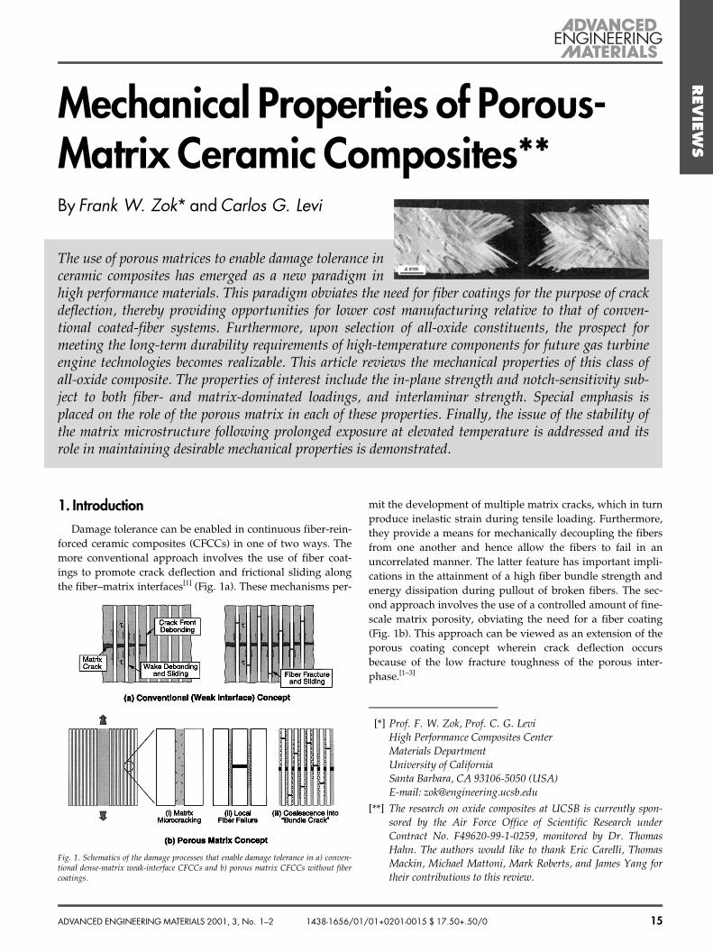
forced ceramic composites (CFCCs) in one of two ways. Themore conventional approach involves the use of fiber coat-ings to promote crack deflection and frictional sliding alongthe fiber±matrix interfaces[1] (Fig. 1a). These mechanisms per-
mit the development of multiple matrix cracks, which in turnproduce inelastic strain during tensile loading. Furthermore,they provide a means for mechanically decoupling the fibersfrom one another and hence allow the fibers to fail in anuncorrelated manner. The latter feature has important impli-cations in the attainment of a high fiber bundle strength andenergy dissipation during pullout of broken fibers. The sec-ond approach involves the use of a controlled amount of fine-scale matrix porosity, obviating the need for a fiber coating(Fig. 1b). This approach can be viewed as an extension of theporous coating concept wherein crack deflection occursbecause of the low fracture toughness of the porous inter-phase.[1±3]
ADVANCED ENGINEERING MATERIALS 2001, 3, No. 1±2 15
±[*] Prof. F. W. Zok, Prof. C. G. Levi
High Performance Composites CenterMaterials DepartmentUniversity of CaliforniaSanta Barbara, CA 93106-5050 (USA)E-mail: [email protected]
[**] The research on oxide composites at UCSB is currently spon-sored by the Air Force Office of Scientific Research underContract No. F49620-99-1-0259, monitored by Dr. ThomasHahn. The authors would like to thank Eric Carelli, ThomasMackin, Michael Mattoni, Mark Roberts, and James Yang fortheir contributions to this review.
The use of porous matrices to enable damage tolerance inceramic composites has emerged as a new paradigm inhigh performance materials. This paradigm obviates the need for fiber coatings for the purpose of crackdeflection, thereby providing opportunities for lower cost manufacturing relative to that of conven-tional coated-fiber systems. Furthermore, upon selection of all-oxide constituents, the prospect formeeting the long-term durability requirements of high-temperature components for future gas turbineengine technologies becomes realizable. This article reviews the mechanical properties of this class ofall-oxide composite. The properties of interest include the in-plane strength and notch-sensitivity sub-ject to both fiber- and matrix-dominated loadings, and interlaminar strength. Special emphasis isplaced on the role of the porous matrix in each of these properties. Finally, the issue of the stability ofthe matrix microstructure following prolonged exposure at elevated temperature is addressed and itsrole in maintaining desirable mechanical properties is demonstrated.
1438-1656/01/01+0201-0015 $ 17.50+.50/0
Fig. 1. Schematics of the damage processes that enable damage tolerance in a) conven-tional dense-matrix weak-interface CFCCs and b) porous matrix CFCCs without fibercoatings.
Zok, Levi/Mechanical Properties of Porous-Matrix Ceramic Composites
REVIE
WS The porous matrix concept has been developed primarily
in the context of oxide-based composites. This developmentcan be attributed to two factors. The first relates to the abilityto produce a controlled pore structure in the matrix at tem-peratures below that wherein the fiber properties begin todegrade. This is accomplished either by partially sintering anetwork of fine particulate or by pyrolysis of a ceramic pre-cursor, both of which are generally more amenable to oxideconstituents than to carbides or nitrides. The second factor isthe shortage of robust fiber coatings available for use withoxide fibers. Such coatings must satisfy a number of require-ments, including thermochemical compatibility with thefibers, oxidation resistance at elevated temperature, lowtoughness, and moderate processing temperature. A numberof oxide coatings with some of the requisite properties havebeen developed recently, including monazite,[4±6] scheelite,[7]
and hibonite.[8,9] The coatings are typically applied by immer-sing the fibers into either a ceramic slurry or a ceramic pre-cursor solution of the coating material, followed by an ele-vated temperature treatment to effect pyrolysis and/ordensification of the coating material. Despite this progress,there remain barriers in the implementation of these coatingsin a large-scale production environment. One of the key prob-lems is the application of the coatings uniformly over thefiber surfaces while keeping the fibers separated, especiallyonce the fibers are woven into a fabric.
Although the porous matrix concept offers new opportu-nities for the development of damage tolerant CFCCs, it alsoposes new challenges in the design and synthesis of micro-
structures that meet the opposing property requirementsplaced on the matrix. In the absence of fiber coatings, thematrix must be sufficiently weak to enable damage toleranceunder fiber-dominated loadings, yet retain adequate strengthto ensure acceptable off-axis properties. In principle, the com-bination of properties can be tailored through changes in thestate of the matrix. For instance, improvements in the interla-minar strength and off-axis in-plane strength can be obtainedby reducing the matrix porosity, but these come at theexpense of a reduction in the damage tolerance under fiber-dominated loadings.[10] These offsetting effects suggest theexistence of an optimum in the matrix properties at which anappropriate balance of properties is achieved. However, theconnections between matrix structure and composite perfor-mance are understood presently at only a rudimentary level.Consequently, the pathway to optimization remains illdefined.
The present article provides an overview of the mechanicalproperties of porous-matrix composites, with emphasis onconnections between properties and matrix microstructure.The article is organized in the following way. The basic con-cepts underlying damage tolerance in porous matrix CFCCsin the absence of fiber coatings are reviewed in Section 2. Sec-tion 3 describes the constituent materials that are currently ofinterest, mainly for use in CFCCs for thermostructural appli-cations (e.g., gas turbine components). The subsequent sec-tions focus on various property groups. Within each, the phe-nomenology of the deformation and/or failure mechanismsand typical values of the relevant material properties are pre-
16 ADVANCED ENGINEERING MATERIALS 2001, 3, No. 1±2
Frank Zok obtained his Ph.D. degree from McMaster University, Canada, in Materials Engineering in1988. He joined the faculty at the University of California at Santa Barbara in 1990 and is presentlyProfessor in the Materials Department. His research interests concern the thermal and mechanicalbehavior of structural composite materials. He is Associate Editor for the Journal of the AmericanCeramics Society and is the author of approximately 100 scientific papers.
Carlos G. Levi received a Ph.D. in Metallurgical Engineering from the University of Illinois at Urbana-Champaign in 1981. He joined the faculty at the University of California, Santa Barbara, in 1984 and ispresently Professor of Materials and Mechanical Engineering. His research emphasizes the understand-ing of microstructure evolution during synthesis and processing, and the application of this understand-ing to the design and manufacture of improved materials. He is a former recipient of the Howe Medaland Grossman Awards from ASM International, currently serves as Vice-Chair of the MaterialsProcessing and Manufacturing Division at TMS, and is a member of the Editorial Board of MaterialsScience and Engineering. He has published approximately 100 scientific papers.
Zok, Levi/Mechanical Properties of Porous-Matrix Ceramic Composites
REVIE
WS
sented. The basic mechanical properties, including in-planetensile behavior and interlaminar strength, are described inSection 4. Issues regarding notch sensitivity are addressed inSection 5. Finally, the role of matrix densification during hightemperature exposure in composite performance is demon-strated in Section 6.
2. Matrix-Enabled Damage ToleranceBroadly, damage tolerance in CFCCs is obtained when the
matrix acts as a mechanical ªbufferº between adjacent fibers,essentially isolating the fibers from one another. To this end,cracks in the matrix must not penetrate into the fibers. Simi-larly, fiber breaks must remain isolated and induce minimalstress concentration in neighboring fibers. A secondary con-sideration involves the resistance to shear deformation withinthe matrix, especially as it relates to the local deformationand stress concentration in the region surrounding a fiberbreak. Transfer of load from a broken fiber to the surroundingmatrix and fibers via shear deformation can increase the loadbearing capacity of the composite as well as enhance the frac-ture energy. However, there is an optimum in the matrixstrength beyond which the load transfer between fibersbecomes excessively localized and the fiber damage spreadsin a correlated manner with attendant reductions in strengthand damage tolerance. The sequence of damage events lead-ing to composite fracture under tensile loading parallel to thefiber direction is illustrated in Figure 1b.
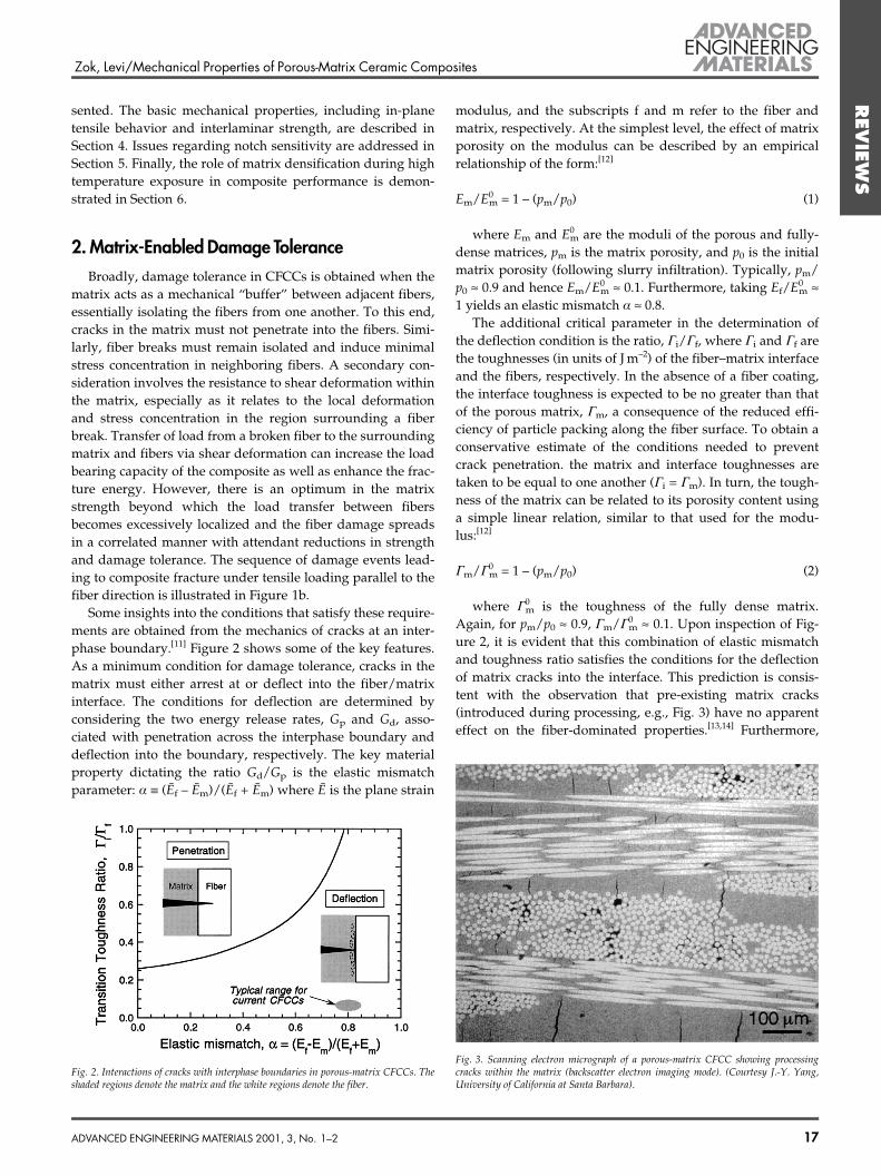
Some insights into the conditions that satisfy these require-ments are obtained from the mechanics of cracks at an inter-phase boundary.[11] Figure 2 shows some of the key features.As a minimum condition for damage tolerance, cracks in thematrix must either arrest at or deflect into the fiber/matrixinterface. The conditions for deflection are determined byconsidering the two energy release rates, Gp and Gd, asso-ciated with penetration across the interphase boundary anddeflection into the boundary, respectively. The key materialproperty dictating the ratio Gd/Gp is the elastic mismatchparameter: a º (EÅ f ± EÅ m)/(EÅ f + EÅ m) where EÅ is the plane strain
modulus, and the subscripts f and m refer to the fiber andmatrix, respectively. At the simplest level, the effect of matrixporosity on the modulus can be described by an empiricalrelationship of the form:[12]
Em/E0m = 1 ± (pm/p0) (1)
where Em and E0m are the moduli of the porous and fully-
dense matrices, pm is the matrix porosity, and p0 is the initialmatrix porosity (following slurry infiltration). Typically, pm/p0 » 0.9 and hence Em/E0
m » 0.1. Furthermore, taking Ef/E0m »
1 yields an elastic mismatch a » 0.8.The additional critical parameter in the determination of
the deflection condition is the ratio, Ci/Cf, where Ci and Cf arethe toughnesses (in units of J m±2) of the fiber±matrix interfaceand the fibers, respectively. In the absence of a fiber coating,the interface toughness is expected to be no greater than thatof the porous matrix, Cm, a consequence of the reduced effi-ciency of particle packing along the fiber surface. To obtain aconservative estimate of the conditions needed to preventcrack penetration. the matrix and interface toughnesses aretaken to be equal to one another (Ci = Cm). In turn, the tough-ness of the matrix can be related to its porosity content usinga simple linear relation, similar to that used for the modu-lus:[12]
Cm/C0m = 1 ± (pm/p0) (2)
where C0m is the toughness of the fully dense matrix.
Again, for pm/p0 » 0.9, Cm/C0m » 0.1. Upon inspection of Fig-
ure 2, it is evident that this combination of elastic mismatchand toughness ratio satisfies the conditions for the deflectionof matrix cracks into the interface. This prediction is consis-tent with the observation that pre-existing matrix cracks(introduced during processing, e.g., Fig. 3) have no apparenteffect on the fiber-dominated properties.[13,14] Furthermore,
ADVANCED ENGINEERING MATERIALS 2001, 3, No. 1±2 17
Fig. 2. Interactions of cracks with interphase boundaries in porous-matrix CFCCs. Theshaded regions denote the matrix and the white regions denote the fiber.
Fig. 3. Scanning electron micrograph of a porous-matrix CFCC showing processingcracks within the matrix (backscatter electron imaging mode). (Courtesy J.-Y. Yang,University of California at Santa Barbara).
Zok, Levi/Mechanical Properties of Porous-Matrix Ceramic Composites
REVIE
WS the figure reveals a significant ªgapº between the critical con-
dition for crack penetration into the fibers and the conditionsobtained in current generations of porous-matrix CFCCs. Thissuggests that the matrix porosity could be reduced further,for the purpose of enhancing the off-axis properties, yet stillsatisfy the crack deflection condition.
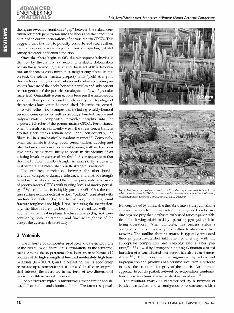
Once the fibers begin to fail, the subsequent behavior isdictated by the nature and extent of inelastic deformationwithin the surrounding matrix and the effect of this deforma-tion on the stress concentration in neighboring fibers. In thiscontext, the relevant matrix property is its ªyield strengthº;the mechanism of yield and subsequent inelastic straining in-volves fracture of the necks between particles and subsequentrearrangement of the particles (analogous to flow of granularmaterials). Quantitative connections between the macroscopicyield and flow properties and the chemistry and topology ofthe matrices have yet to be established. Nevertheless, experi-ence with other fiber composites, including weakly-bondedceramic composites as well as strongly bonded metal- andpolymer-matrix composites, provides insights into theexpected behavior of the porous-matrix CFCCs. For instance,when the matrix is sufficiently weak, the stress concentrationsaround fiber breaks remain small and, consequently, thefibers fail in a stochastically random manner.[15] Conversely,when the matrix is strong, stress concentrations develop andfiber failure spreads in a correlated manner, with each succes-sive break being more likely to occur in the vicinity of anexisting break or cluster of breaks.[16] A consequence is thatthe in-situ fiber bundle strength is intrinsically stochastic.Furthermore, the mean fiber bundle strength is reduced.
The expected correlations between the fiber bundlestrength, composite damage tolerance, and matrix strengthhave been largely confirmed through experiments on a familyof porous-matrix CFCCs with varying levels of matrix porosi-ty.[10] When the matrix is highly porous (»35±40 %), the frac-ture surface exhibits extensive fiber ªpulloutº, consistent withrandom fiber failure (Fig. 4a). In this case, the strength andfracture toughness are high. Upon increasing the matrix den-sity, the fiber failure sites become more correlated with oneanother, as manifest in planar fracture surfaces (Fig. 4b). Con-comitantly, both the strength and fracture toughness of thecomposite decrease dramatically.[10]
3. MaterialsThe majority of composites produced to date employ one
of the Nextel oxide fibers (3M Corporation) as the reinforce-ment. Among these, preference has been given to Nextel 610because of its high strength at low and moderately high tem-peratures (to ~1000 �C), and to Nextel 720 for its good creepresistance up to temperatures of ~1200 �C. In all cases of prac-tical interest, the fibers are in the form of two-dimensionalfabric in an 8-harness satin weave.
The matrices are typically mixtures of either alumina and sil-ica,[17±20] or mullite and alumina.[10,13,14,21] The former is typical-
ly incorporated by immersing the fabric into a slurry containingalumina particulate and a silica-forming polymer, thereby pro-ducing a pre-preg that is subsequently used for component fab-rication following established lay-up, curing, pyrolysis and sin-tering operations. When complete, this process yields acontiguous nanoporous silica phase within the alumina particlenetwork. The mullite±alumina matrix is typically producedthrough pressure-assisted infiltration of a slurry with theappropriate composition and rheology into a fiber pre-form,[13,22] followed by drying and sintering. (Vibration-assistedintrusion of a consolidated wet matrix has also been demon-strated.[23]) The process can be augmented by subsequentimpregnation and pyrolysis of a ceramic precursor in order toincrease the structural integrity of the matrix. An alternateapproach to bond a particle network by evaporation±condensa-tion in reactive atmospheres has also been explored.[23]
The resultant matrix is characterized by a network ofbonded particulate and a contiguous pore structure with a
18 ADVANCED ENGINEERING MATERIALS 2001, 3, No. 1±2
Fig. 4. Fracture surfaces of porous matrix CFCCs, showing a) un-correlated and b) cor-related fiber fractures in CFCCs with weak and strong matrices, respectively. (CourtesyMichael Mattoni, University of California at Santa Barbara).
Zok, Levi/Mechanical Properties of Porous-Matrix Ceramic Composites
REVIE
WS
size scale comparable to the particle size (£1 lm). The porosi-ty levels required to enable damage tolerance typically fall inthe range of »30±40 %.[10,21] Stability of this pore structure inservice is essential to the long-term preservation of the dam-age tolerant properties. For this reason, the major phase inthese matrices should ideally form a contiguous network thatinhibits shrinkage at elevated temperature, thereby providingstability to the pore structure, whereas the minor phaseserves as a binder to impart mechanical strength.[14] In thiscontext, mullite is preferred over alumina as the major phasebecause it exhibits more sluggish sintering kinetics and istherefore more resistant to shrinkage upon prolonged expo-sure to elevated temperatures.[13,14]
In practical situations, there is always some shrinkageassociated with drying, pyrolysis and sintering (dependingon the matrix), leading to the formation of matrix cracks pre-dominantly normal to the fiber directions, such as thoseshown in Figure 3. Similar cracks are obtained in most C- andSiC-fiber reinforced C-matrix composites.[24,25] However,these cracks do not appear to be particularly detrimental tothe important mechanical properties of the composite.[14,21]
This result supports the notion that matrix cracks do not pe-netrate into the fibers, as described in the preceding section.
4. Basic Mechanical PropertiesIn composites with 2-dimensional cross-ply fiber architec-
tures, the basic in-plane mechanical properties are obtainedfrom uniaxial tensile tests both along the fiber axis (in the 0�/90� orientation) and an angle of 45�. The two test configura-tions provide the requisite information on the fiber-domi-nated and matrix-dominated properties, respectively. Addi-tional information required for mechanical design involvesthe interlaminar properties, measured in shear and/or ten-sion. The general mechanical characteristics and typical prop-erty values obtained from such tests are summarized below.
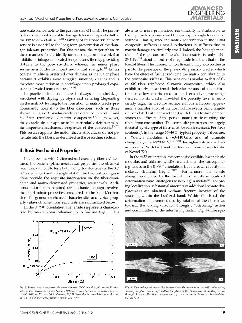
In the 0�/90� orientation, the tensile response is character-ized by nearly linear behavior up to fracture (Fig. 5). The
absence of more pronounced non-linearity is attributable tothe high matrix porosity and the correspondingly low matrixstiffness. That is, since the matrix contribution to the initialcomposite stiffness is small, reductions in stiffness due tomatrix damage are similarly small. Indeed, the Young's mod-ulus of the porous mullite±alumina matrix is only ~20±25 GPa:[21] about an order of magnitude less than that of theNextel fibers. The absence of non-linearity may also be due inpart to the presence of the pre-existing matrix cracks, whichhave the effect of further reducing the matrix contribution tothe composite stiffness. This behavior is similar to that of C-or SiC-fiber reinforced C-matrix composites, which alsoexhibit nearly linear tensile behavior because of a combina-tion of a low matrix modulus and extensive processing-derived matrix cracks. Provided the porosity level is suffi-ciently high, the fracture surface exhibits a fibrous appear-ance, a manifestation of the fiber failure events being largelyun-correlated with one another (Fig. 4a). This feature demon-strates the efficacy of the porous matrix in de-coupling thefibers from one another. The composite properties are largelydictated by the type of fiber used for reinforcement. For fibercontents, f, in the range 35±40 %, typical property values are:i) Young's modulus, E » 60±110 GPa, and ii) ultimatestrength, ru » 140±220 MPa;[13,17,21] the higher values are char-acteristic of Nextel 610 and the lower ones are characteristicof Nextel 720.
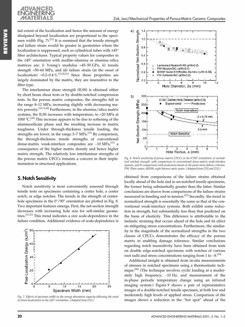
In the ±45� orientation, the composite exhibits lower elasticmodulus and ultimate tensile strength than the correspond-ing values in the 0�/90� orientation, but a greater capacity forinelastic straining (Fig. 5).[20,21] Furthermore, the tensilestrength is dictated by the formation of a diffuse localizeddeformation band, analogous to necking in metals.[21] Follow-ing localization, substantial amounts of additional remote dis-placement are obtained without fracture because of thestraining within the localized band. Within this band, thedeformation is accommodated by rotation of the fiber towstowards the loading direction through a ªscissoringº actionand comminution of the intervening matrix (Fig. 6). The spa-
ADVANCED ENGINEERING MATERIALS 2001, 3, No. 1±2 19
Fig. 5. Typical tensile properties of a porous-matrix CFCC in both 0�/90� and ±45� orien-tations. The material comprises Nextel 610 fibers in an 8-harness satin weave and a ma-trix of ~80 % mullite and 20 % alumina [13,21]. Virtually the same behavior is obtainedin CFCCs with matrices of alumina and silica [17,20].
Fig. 6. Two orthogonal views of a fractured tensile specimen in the ±45� orientation,showing a) fiber ªscissoringº within the plane of the fabric, and b) swelling in thethrough-thickness direction, a consequence of comminution of the matrix during defor-mation [13].
Zok, Levi/Mechanical Properties of Porous-Matrix Ceramic Composites
REVIE
WS tial extent of the localization and hence the amount of energy
dissipated beyond localization are proportional to the speci-men width (Fig. 7).[21] It is surmised that the tensile strengthand failure strain would be greater in geometries where thelocalization is suppressed, such as cylindrical tubes with ±45�fiber architectures. Typical property values for composites inthe ±45� orientation with mullite±alumina or alumina±silicamatrices are: i) Young's modulus »45±50 GPa, ii) tensilestrength »50±60 MPa, and iii) failure strain (at the onset oflocalization) »0.2±0.4 %.[13,20,21] Since these properties arelargely dominated by the matrix, they are insensitive to thefiber type.
The interlaminar shear strength (ILSS) is obtained eitherby short beam shear tests or by double-notched compressiontests. In the porous matrix composites, the strengths fall inthe range 8±12 MPa, increasing slightly with decreasing ma-trix porosity.[10,13,20] Furthermore, in the alumina/silica matrixsystems, the ILSS increases with temperature, to »20 MPa at1000 �C.[20] This increase appears to be due to softening of thealuminosilicate phase and the resulting increase in matrixtoughness. Under through-thickness tensile loading, thestrengths are lower, in the range 3±7 MPa.[17] By comparison,the through-thickness tensile strengths of conventionaldense-matrix weak-interface composites are ~10 MPa,[17] aconsequence of the higher matrix density and hence highermatrix strength. The relatively low interlaminar strengths ofthe porous matrix CFCCs remains a concern in their imple-mentation in structural applications.
5. Notch SensitivityNotch sensitivity is most conveniently assessed through
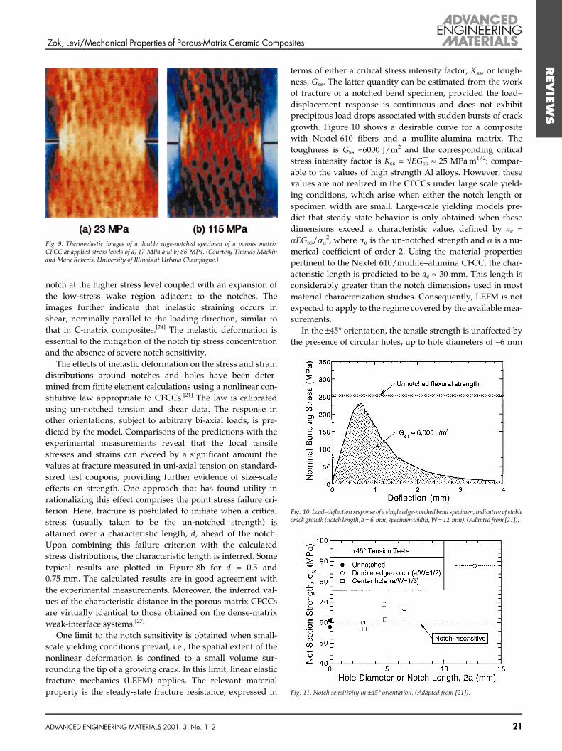
tensile tests on specimens containing a center hole, a centernotch, or edge notches. The trends in the strength of center-hole specimens in the 0�/90� orientation are plotted in Fig. 8.Two important features emerge. First, the net-section strengthdecreases with increasing hole size for self-similar geome-tries.[13,21] This trend indicates a size scale-dependence in thefailure condition. Additional evidence of scale-dependence is
obtained from comparisons of the failure strains obtainedlocally ahead of the hole and in un-notched tensile specimens,the former being substantially greater than the latter. Similarconclusions are drawn from comparisons of the failure strainsmeasured in bending and in tension.[21] Secondly, the trend innormalized strength is essentially the same as that of the con-ventional weak-interface systems. Both exhibit some reduc-tion in strength, but substantially less than that predicted onthe basis of elasticity. This difference is attributable to theinelastic straining that occurs ahead of the hole and its effecton mitigating stress concentrations. Furthermore, the similar-ity in the magnitude of the normalized strengths in the twoclasses of CFCCs demonstrates the efficacy of the porousmatrix in enabling damage tolerance. Similar conclusionsregarding notch insensitivity have been obtained from testson double edge-notched specimens with notches of variousroot radii and stress concentrations ranging from 1 to ~8.[19]
Additional insight is obtained from in-situ measurementsof stresses in notched specimens using a thermoelastic tech-nique.[26] (The technique involves cyclic loading at a moder-ately high frequency, ~10 Hz, and measurement of thein-phase periodic temperature change using an infraredimaging system.) Figure 9 shows a pair of representativeimages of a double-notched tensile specimen, at both low andmoderately high levels of applied stress. Comparison of theimages shows a reduction in the ªhot spotº ahead of the
20 ADVANCED ENGINEERING MATERIALS 2001, 3, No. 1±2
Fig. 7. Effects of specimen width on the energy absorption capacity following the onsetof strain localization in the ±45� orientation. (Adapted from [21].)
Fig. 8. Notch sensitivity of porous matrix CFCCs in the 0�/90� orientation: a) normal-ized notched strength, with comparisons to conventional dense-matrix weak-interfacesystems, and b) comparisons with predictions based on the point stress failure criterion.PW: Plain weave; 8HSW: eight harness satin weave. (Adapted from [13] and [21].)
Zok, Levi/Mechanical Properties of Porous-Matrix Ceramic Composites
REVIE
WS
notch at the higher stress level coupled with an expansion ofthe low-stress wake region adjacent to the notches. Theimages further indicate that inelastic straining occurs inshear, nominally parallel to the loading direction, similar tothat in C-matrix composites.[24] The inelastic deformation isessential to the mitigation of the notch tip stress concentrationand the absence of severe notch sensitivity.
The effects of inelastic deformation on the stress and straindistributions around notches and holes have been deter-mined from finite element calculations using a nonlinear con-stitutive law appropriate to CFCCs.[21] The law is calibratedusing un-notched tension and shear data. The response inother orientations, subject to arbitrary bi-axial loads, is pre-dicted by the model. Comparisons of the predictions with theexperimental measurements reveal that the local tensilestresses and strains can exceed by a significant amount thevalues at fracture measured in uni-axial tension on standard-sized test coupons, providing further evidence of size-scaleeffects on strength. One approach that has found utility inrationalizing this effect comprises the point stress failure cri-terion. Here, fracture is postulated to initiate when a criticalstress (usually taken to be the un-notched strength) isattained over a characteristic length, d, ahead of the notch.Upon combining this failure criterion with the calculatedstress distributions, the characteristic length is inferred. Sometypical results are plotted in Figure 8b for d = 0.5 and0.75 mm. The calculated results are in good agreement withthe experimental measurements. Moreover, the inferred val-ues of the characteristic distance in the porous matrix CFCCsare virtually identical to those obtained on the dense-matrixweak-interface systems.[27]
One limit to the notch sensitivity is obtained when small-scale yielding conditions prevail, i.e., the spatial extent of thenonlinear deformation is confined to a small volume sur-rounding the tip of a growing crack. In this limit, linear elasticfracture mechanics (LEFM) applies. The relevant materialproperty is the steady-state fracture resistance, expressed in
terms of either a critical stress intensity factor, Kss, or tough-ness, Gss. The latter quantity can be estimated from the workof fracture of a notched bend specimen, provided the load±displacement response is continuous and does not exhibitprecipitous load drops associated with sudden bursts of crackgrowth. Figure 10 shows a desirable curve for a compositewith Nextel 610 fibers and a mullite-alumina matrix. Thetoughness is Gss »6000 J/m2 and the corresponding criticalstress intensity factor is Kss = ÖEGss » 25 MPa m1/2: compar-able to the values of high strength Al alloys. However, thesevalues are not realized in the CFCCs under large scale yield-ing conditions, which arise when either the notch length orspecimen width are small. Large-scale yielding models pre-dict that steady state behavior is only obtained when thesedimensions exceed a characteristic value, defined by ac »aEGss/ru
2, where ru is the un-notched strength and a is a nu-merical coefficient of order 2. Using the material propertiespertinent to the Nextel 610/mullite±alumina CFCC, the char-acteristic length is predicted to be ac » 30 mm. This length isconsiderably greater than the notch dimensions used in mostmaterial characterization studies. Consequently, LEFM is notexpected to apply to the regime covered by the available mea-surements.
In the ±45� orientation, the tensile strength is unaffected bythe presence of circular holes, up to hole diameters of ~6 mm
ADVANCED ENGINEERING MATERIALS 2001, 3, No. 1±2 21
Fig. 9. Thermoelastic images of a double edge-notched specimen of a porous matrixCFCC at applied stress levels of a) 17 MPa and b) 86 MPa. (Courtesy Thomas Mackinand Mark Roberts, University of Illinois at Urbana Champagne.)
Fig. 10. Load±deflection response of a single edge-notched bend specimen, indicative of stablecrack growth (notch length, a = 6 mm, specimen width, W = 12 mm). (Adapted from [21]).
Fig. 11. Notch sensitivity in ±45� orientation. (Adapted from [21]).

Zok, Levi/Mechanical Properties of Porous-Matrix Ceramic Composites
REVIE
WS (Fig. 11).[21] Indeed, there appears to be some evidence of
notch strengthening at the larger diameters, by ~10 %. Failureoccurs through a localization process closely analogous tothat in the un-notched tension tests, with minimal fiber fail-ure. Furthermore, the local strains at the hole edges at theload maximum reach values of 0.7±0.8 %, ~2 to 3 times thefailure strain measured in uniaxial tension.[21] Evidently theconstraints associated with the hole suppress the onset oflocalization within the most heavily stressed regions (imme-diately ahead of the hole), resulting in the observed notchinsensitivity. In the presence of long, relatively sharp notches,a transition in failure mechanisms occurs, to one involvingfiber fracture (Fig. 12).[13] The corresponding strengths areincreased substantially, by ~50 % over the values obtained inboth the un-notched and the center-hole specimens (Fig. 11).The observed notch ªstrengtheningº appears to be unique tothe porous matrix CFCCs, in part because of the relativelylow values of strength obtained under matrix-dominatedloadings (in the absence of notches) relative to the fiber bun-dle strength.
6. Long-Term StabilityThe long-term performance of porous matrix CFCCs at the
targeted service temperatures (~1000±1200 �C) is dictated bythe stability of the microstructures of both the fibers and thematrix. In the fibers, strength degradation results from graingrowth. In the matrix, degradation involves sintering, subjectto the constraints imposed by the dense fibers, leading to aloss in damage tolerance. Furthermore, the degradation infiber strength may increase the requirements on the allowablematrix properties to enable damage tolerance, thereby reduc-ing composite toughness, potentially with little or no changein the matrix microstructure. These synergistic degradationmechanisms have yet to be quantified.
Fibers comprised of pure alumina (e.g., Nextel 610) areparticularly susceptible to grain growth and strength reduc-tion at temperatures ³1000 �C. The problem is less severe inalumina-mullite fibers (e.g., Nextel 720) because of the con-straint of the mullite on grain growth. Maintaining a stablematrix pore structure is an equally important and difficultchallenge. Because of geometric considerations of infiltrationand packing of matrix particles around the fibers, the matrix
particles are necessarily of a fine size scale, making themespecially prone to subsequent sintering and densification.Indeed, the development of a pore structure that can be pro-duced at moderate temperatures (to avoid fiber degradation)yet be retained over long periods at elevated temperaturesremains one of the critical outstanding challenges in thedevelopment of porous matrix CFCCs.
Among the porous matrix CFCCs developed to date,[13,17,18]
the one comprising the mullite±alumina matrix appears toexhibit the best potential for long-term stability. This stabilityhas been demonstrated through measurement of retainedstrength following 1000 h exposures at elevated tempera-tures. Figure 13 shows the trends for two systems, both rein-forced with Nextel 720 fibers, but with different matrices: alu-mina±silica[18] and mullite±alumina.[28] Strength degradationoccurs in the former system at temperatures ³1000 �C. By con-trast, there is virtually no strength reduction in the latter sys-tem up to 1200 �C. Furthermore, the fracture surfaces of themullite/alumina matrix system exhibit the desired fibrousappearance,[28] consistent with high damage tolerance,whereas the alumina±silica system fails in a brittle planarmanner.[18] Despite the absence of strength reduction in themullite±alumina system, there is some evidence of sintering,as manifest in elevations in the matrix hardness as well asincreases in the opening displacement of the processing-in-duced cracks.[28] However, the magnitude of these changes isinsufficient to degrade the fiber bundle strength over the1000 h period, making the material an attractive candidatefor some gas turbine applications requiring durability overextended time periods. Nevertheless, it is anticipated that yetlonger exposures eventually will eventually lead to some lossin damage tolerance, analogous to that in the alumina±silicasystem. The time scale associated with this degradationremains to be established.
7. Concluding RemarksWork to date has demonstrated the significant promise of
the porous-matrix approach in enabling damage tolerance in
22 ADVANCED ENGINEERING MATERIALS 2001, 3, No. 1±2
Fig. 12. Fiber failure in a notched porous-matrix CFCC specimen in the ±45� orienta-tion [13].
Fig. 13. Effects of matrix composition on the retained (room temperature) strength ofporous matrix CFCCs reinforced with Nextel 720 fibers following high temperatureexposures in air [18,28].
Zok, Levi/Mechanical Properties of Porous-Matrix Ceramic Composites
REVIE
WS
ceramic matrix composites, comparable to that resulting fromthe use of fiber coatings. Coupled with compositions basedon all-oxide constituents, this approach offers an excellentopportunity to produce affordable components that have therequisite durability for long-term applications in energy-con-version systems. While the behavior of these materials is stillnot well understood, attributes such as their relative notchinsensitivity make them attractive for incorporation into adesign environment that is still largely dominated by prac-tices evolved from the use of metals.
The primary drawback of these materials at the presenttime is an inadequate creep strength, owing primarily to thelimited high temperature properties of available oxide fibers.As the properties of oxide fibers improve, the basic porous-matrix design should be extendable in principle to highertemperatures. Matrix compositions with the requisite charac-teristics to provide stability in the porous microstructure arelikely to be similar to those used for the more advanced fibers,and hence compatible with them. Additional issues arise fromthe porous microstructure itself, which may have to be imper-vious to gas flow for some applications, or render the compos-ite susceptible to penetration by moisture or contaminants.An interesting challenge is to make the composite imperme-able, which would imply partially sealing and/or breakingthe continuity of the porosity, without impairing its damagetolerance. These problems are currently under investigation.
Received:April 12, 2000Final version: July 19, 2000
±[1] A. G. Evans, F. W. Zok, J. B. Davis, Compos. Sci. Technol.
1991, 42, 3.[2] J. B. Davis, J. P. A. Löfvander, A. G. Evans, J. Am.
Ceram. Soc. 1993, 76, 1249.[3] T. J. Mackin, J. Y. Yang, C. G. Levi, A. G. Evans, Mater.
Sci. Eng. A 1993, 161, 285.[4] P. E. D. Morgan, D. B. Marshall, J. Am. Ceram. Soc. 1995,
78, 1553, also 1995, 78, 2574.[5] S. M. Johnson, Y. Blum, C. Kanazawa, H.-J. Wu, J. R.
Porter, P. E. D. Morgan, D. B. Marshall, D. Wilson, KeyEng. Mater. 1997, 127±131, 231.
[6] D. B. Marshall, J. B. Davis, P. E. D. Morgan, J. R. Porter,Key Eng. Mater. 1997, 127±131, 27.
[7] R. W. Goettler, S. Sambasivan, V. Dravid, Ceram. Eng.Sci. Proc. 1997, 18, 279.
[8] M. K. Cinibulk, R. S. Hay, J. Am. Ceram. Soc. 1996, 79,1233.
[9] M. G. Cain, R. L. Cain, M. H. Lewis, J. Am. Ceram. Soc.1997, 80, 1873.
[10] M. Mattoni, J. Y. Yang, C. G. Levi, F. W. Zok, submittedto J. Am. Ceram. Soc.
[11] M. Y. He, J. W. Hutchinson, Int. J. Solids Struct. 1989, 25,1053.
[12] D. C. C. Lam, F. F. Lange, A. G. Evans, J. Am. Ceram.Soc. 1994, 77, 2113.
[13] C. G. Levi, J. Y. Yang, B. J. Dalgleish, F. W. Zok, A. G.Evans, J. Am. Ceram. Soc. 1998, 81, 2077.
[14] C. G. Levi, F. W. Zok, J.-Y. Yang, M. Mattoni, J. P. A.Löfvander, Z. Metallkd. 1999, 90, 1037.
[15] W. A. Curtin, J. Amer. Ceram. Soc. 1991, 74, 2837.[16] M. Ibnabdeljalil, W. A. Curtin, Int. J. Solids Struct. 1997,
34, 2649.[17] L. P. Zawada, Ceram. Eng. Sci. Proc. 1998, 19, 327.[18] R. Jurf, S. Butner, Proc. Int. Gas Turbine and Aeroengine
Congress and Exhibition, Indianapolis, IN 1999.[19] V. Kramb, R. John, L. P Zawada, J. Am. Cram. Soc. 1999,
82, 3087.[20] L. P. Zawada, R. S. Hay, S. S. Lee, J. Staehler, submitted
to J. Am. Ceram. Soc.[21] J. A. Heathcote, X.-Y. Gong, J. Yang, U. Ramamurty,
F. W. Zok, J. Am. Ceram. Soc. 1999, 82, 2721.[22] F. F. Lange, W. C. Tu, A. G. Evans, Mater. Sci. Eng. A
1995, 195, 145.[23] J. Haslam, K. E. Berroth, F. F. Lange, J. Eur. Ceram. Soc.
2000, 20, 607.[24] F. Heredia, S. M. Spearing, T. J. Mackin, M. Y He, A. G.
Evans, J. Am. Ceram. Soc. 1994, 77, 2817.[25] K. R. Turner, J. S. Speck, A. G. Evans, J. Am. Ceram. Soc.
1995, 78, 1841.[26] T. J. Mackin, M. C. Roberts, J. Am. Ceram. Soc. 2000, 83,
227.[27] J. C. McNulty, F. W. Zok, G. M. Genin, A. G. Evans, J.
Am. Ceram. Soc. 1999, 82, 1217.[28] E. Carelli, H. Fujita, J.-Y. Yang, F. W. Zok, submitted to
J. Am. Ceram. Soc.
ADVANCED ENGINEERING MATERIALS 2001, 3, No. 1±2 23
______________________