modeling 3-d woven ceramic matrix composites · modeling of 3-d woven ceramic matrix composites ......
TRANSCRIPT
MODELING OF 3-D WOVEN CERAMIC MATRIX COMPOSITES
Pappu L.N. Murthy and Roy M. Sullivan NASA Glenn Research Center, Cleveland, OHIO 44 13 5
and Subodh K. Mital
University of Toledo, Toledo, OHIO 43606
ABSTRACT
Tlu-ee different approaches are being pursued at the NASA Glenn Research Center to predict the thennostructural behavior of three-dimensional woven ceramic matrix composites. These are: a niicromechanics-based approach using W-CEMCAN (Woven Ceramic h4atrix Composite Analyzer), a laminate analogy method and a structural frame approach (based on the finite element method). All tlu-ee techniques are applied to predict the tliermomechanical properties of a tlu-ee-dimensional woven angle interlock C/SiC composite. Tlie properties are predicted for room temperature and 1100 "C and the predicted properties are compared to measurements. General observations regarding the tlu-ee approaches for tlu-ee-dimensional composite modeling are discussed.
KEYWORDS: Ceramic Matrix Composites, Laminate Analogy, Binary Models, Structural Frame Model, Angle Interlock, 3-D Woven Composites
1. BACKGROUND/INTRODUCTION
Ceramic matrix composites (CMC) are emerging materials with high potential payoffs in many aerospace applications. In fact, the development of CMC teclmology is considered by many as essential to tlie realization of tlie next generation reusable launcli system. The low density of CMCs and their ability to maintain strength and stiffiiess at high temperatures are tlie primary advantages of CMCs over the more conventional launch vehicle and propulsion system materials. Tlie benefits associated with utilizing CMCs will be realized largely by increasing tlie engine operating temperature, raising temperature safety margins, avoiding tlie need for cooling, and possibly improved damping capacity, while reducing tlie launch vehicle weight. No other
This is a preprint or reprint of a paper intended for presentation at a conference. Because changes may be made before formal publication, this is made available with the understanding that it will not be cited or reproduced without the permission of the author.
1
https://ntrs.nasa.gov/search.jsp?R=20030020624 2018-06-13T07:16:57+00:00Z

material system can accomplish all of these things. However, CMC’s suffer from high manufacturing costs a i d insufficient characterization. Designers do not have an available database with design allowables to have tlie required confidence in the structures made of CMCs. Credible structural life and performance predictions depend upon understanding composite degradation meclianisms and stress distributions in various constituents. References such as the MIL-handbook that deal with CMCs are in tlie preliminary stages of development and by their nature represent a work in progress as tlie state of the art evolves.
Before CMCs find extensive use in space applications, their reliability as hot structures sustaining harsh service environments must be well established. This involves extensive testing a id characterization of tlie materials as well as tlie development of predictive desigidanalysis tools. Material characterization efforts based solely on testing are impractical for the time and costs involved. Analytical predictive tools are therefore necessary to bring down tlie costs and reduce tlie design cycle time. A synergistic combination of both is therefore desirable for achieving success using the advanced CMC technology. Tlie present paper addresses the latter, namely the development of accurate mathematical models that predict the tlierinostructural behavior over wide temperature ranges. The primary focus is on modeling a 3-D woven carbon silicon carbide (C/SiC) composite. Herein, three different approaches are applied to model the material. Two of the approaches have their foundations in the familiar micromecliaiiics-based approaclies [l]. The third one is based on a structural frame model and resembles closely the biliary models 112-31. Predictions of tlie CMC properties at room as well as high temperatures are the primary objective of these models. The predictions are compared with tlie limited available experimental data. In addition, conclusions regarding tlie effectiveness and accuracy of the various models are drawn based uipon tlie results.
2. APPROACHES
Tlie primary focus of tlie present study is on the development of methodologies for predicting tlie properties of 3-D woven angle interlock ceramic matrix composites. As mentioned above, t h e e different modeling approaches are applied to model tlie 3-D \~70veii composite namely, 1 ) the structural frame model approach, 2) a micromechanics-based approach and 3) a laminate analogy model-based approach. In tlie structural frame model approach, the CMC medium is replaced by a structural fiameworlc of axial/bending elements a id springs. Tlie structural frame is then solved using tlie finite element technique. In this sense, it is analogous to the ‘binary models’ [2.3]. The second and tlie third approaches both have their foundations in niicronieclianics. In tlie microiiiecli~iics-based approach, a representative volume element capturing all the local details regarding fiber architecture, interface details, fiber and matrix constituents within tlie tow as well as between the tows is utilized. A mechanics of the materials approach is then applied to arrive at effective properties. Tlie overall properties of tlie laminate are then obtained by successive application of classical lamination theory. In tlie laminate analogy inodeling I I I. the representative volume element is modeled as a superposition of several sub-laminates that capture the fiber architectural details. Tlie properties of each lamina are determined using a conventional niicromechanics approach similar to the one used in tlie previous approach. The superposition of tlie individual sub-laniinates is achieved using classical lamination theory.
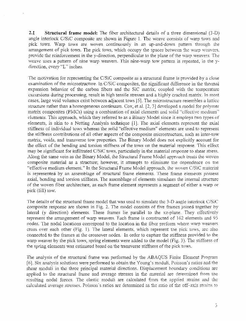
2.1 Structural frame model: The fiber architectural details of a t h e e dimensional (3-D) angle interlock C/SiC composite are sliown in Figure 1. The weave consists of warp tows aiid pick tows. Warp tows are woven contiiiuously in a11 up-and-down pattern through the arrangement of pick tows. The pick tows, which occupy tlie spaces between the 117arp weavers. provide tlie reinforcement in the y-direction, perpendicular to the plane of the warp weavers. ’The weave uses a pattern of iiiiie warp weavers. This nine-wa1.y tow pattern is repeated, in the y- direction, every “L” iiiclies.
Tlie iiiotivatioii for representing the C/SiC composite as a structural frame is provided by a close examination of the microstructure. In C/SiC composites, tlie significant difference in the tlierinal expansion behavior of tlie carbon fibers and the S ic matrix, coupled with the temperature excursions during processing, result in high tensile stresses and a highly cracked matrix. In iiiost cases, large void volumes exist between adjacent tows [5]. Tlie microstructure resembles a M i c e structure rather than a homogeneous continuum. Cox, et al. [2, 31 developed a iiiodel for polymer matrix composites (PMCs) using a combination of axial elements and solid “eKective medium” elemelits. This approach, which they referred to as a Biliary Model since it employs two types of elements, is akin to a Netting Analysis teclmique [l]. Tlie axial elements represent tlie axial stiffiiess of individual tows whereas the solid “effective medium” elements are used to represent the stiffiiess coiitributioiis of all other aspects of the composite microstructure, such as inter-tow matrix, voids, and transverse tow properties. The Binary Model does not explicitly account for tlie effect of tlie bending aiid torsion stiffness of the tows on the material response. This effect may be significant for infiltrated C/SiC tows, particularly in the iiiaterial response to shear stress. Along tlie same vein as tlie Binary Model, tlie Structural Frame Model approach treats the ~voven composite material as a structure; however, it attempts to eliminate the clependeiice on the “effective niediuni element.” In the Structural Frame Model approach, the woven C/SiC material is represented by an assemblage of structural frame elements. These frame eleiiieiits possess axial, bending and torsion stiffness. Tlie assemblage of eleiiieiits simulates the iiiteriial structure of the woven fiber architecture, as each frame element represents a segment of either a warp or pick (fill) tow.
The details of the structural fi-ame model that was used to siinulate the 3-D angle interlock C/SiC coinposite response are sliown in Fig. 2. Tlie model consists of five frames joined together b y lateral (y direction) elements. These frames lie parallel to tlie xz-plane. They effectively represent the arrangement of warp weavers. Each frame is constructed of 162 elements and 0 5 nodes. The nodal locatioiis correspond to the locatioii in tlie fiber preform where waq3 weavers cross over each other (Fig. 1). The lateral elements, which represent the pick tows, are also connected to the frames at the crossover nodes. In order to capture the stiffness provided to the warp weaver by the pick tows, spring elements were added to the model (Fig. 3). The stiffiiess of tlie spring elements was estimated based on tlie transverse stiffiiess of the pick tows.
The aialysis of the structural frame was performed by tlie ABAQUS Finite Element Program [6]. Six analysis solutioiis were performed to obtain the Young’s moduli, Poissoii’s ratios and the shear moduli in the t h e e principal material directions. Displaceiiieiit bouiidary conditions are applied to the structural frame and average stresses in the material are determined from the resulting nodal forces. The elastic moduli are calculated from the applied strains and tlie calculated average stresses. Poissoii’s ratios are determined as tlie ratio of the off-axis strains to
7 J
tlie applied strain. Tlie boundary conditions wliicli were applied for each analysis solution are shown in Table 1.
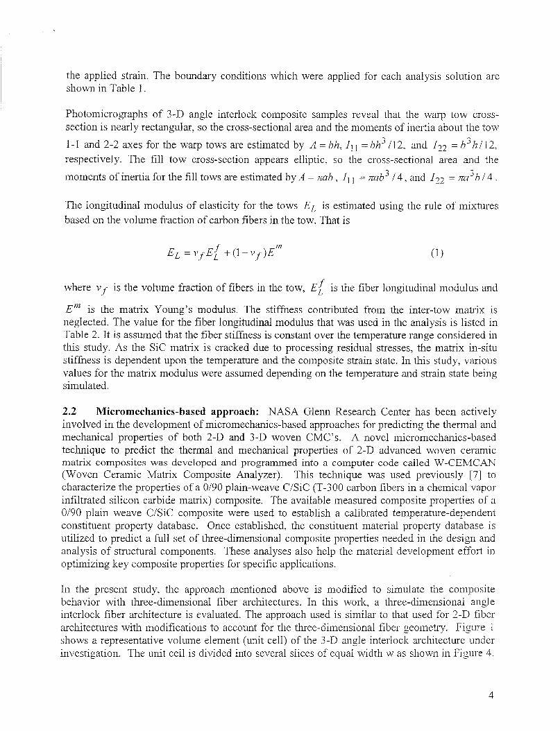
Photomicrographs of 3 -D angle interlock composite samples reveal tliat tlie warp tow cross- section is nearly rectangular, so tlie cross-sectional area and tlie inomelits of inertia about the tow
1-1 and 2-2 axes for tlie warp tows are estimated by A = hh, I, 1 = hh’ /12, and f22 = h’l7 / 12, respectively. Tlie fill tow cross-section appears elliptic, so the cross-sectional area and the
moments of inertia for tlie fill tows are estimated by A = m h , 1, = Tab’ / 4 , and J 3 2 - = Ea ’ h / 4 . 1
The longitudiiial modulus of elasticity for the tows E, is estimated using the rule of mixtures based 011 tlie volume fraction of carbon fibers in tlie tow. That is
where i1.f is tlie volume fraction of fibers in tlie tow, E L f is tlie fiber loiigitudiiial modulus and
E” is tlie matrix Young’s modulus. The stiffness contributed froin tlie inter-tow matrix is neglected. The value for tlie fiber longitudinal modulus tliat was used in tlie analysis is listed in Table 2. It is assumed that the fiber stiffiiess is coiistaiit over tlie temperature range considered in this study. As tlie S i c matrix is cracked due to processing residual stresses, tlie matrix in-situ stiffiess is dependent upon the temperature a id the composite strain state. In this study, various values for tlie matrix modulus were assumed depending on tlie temperature and strain state being simulated.
2.2 Micromechanics-based approach: NASA Glenn Research Center has been actively involved in tlie developineiit of inicromechanics-based approaches for predicting tlie thermal a id mechanical properties of both 2-D and 3 -D woven CMC’s. A novel iiiicro~iiecha~iics-based technique to predict the thermal and mechanical properties of 2-D advanced woven ceramic iiiatrix coinposites was developed and programmed into a computer code called W-CEMCAN (Woven Ceramic Matrix Composite Analyzer). This technique was used previously [7] to characterize the properties of a 0/90 plain-weave C/SiC (T-300 carbon fibers in a chemical vapor infiltrated silicon carbide matrix) composite. Tlie available measured composite properties of a 0/90 plain weave C/SiC composite were used to establish a calibrated teiii~erature-depeiideiit constitueiit property database. Once established, tlie constituent material property database is utilized to predict a full set of three-dimensional coinposite properties needed in tlie design a id analysis of structural components. These analyses also help tlie material development effoi-t in optimizing key composite properties for specific applications.
In tlie present study, tlie approach ineiitioiied above is modified to simulate the coiiiposite behavior with tl.11-ee-dimensional fiber architectures. In this work, a tl~ee-dimensional angle interlock fiber architecture is evaluated. Tlie approach used is similar to tliat used for 2-D fiber architectures with modifications to account for tlie tlu-ee-dimensional fiber geometry. Figure 1 shows a representative volume element (unit cell) of tlie 3 -D angle interlock architecture under investigation. Tlie unit cell is divided into several slices of equal width w as shown in Figure 4.
4

The iiuinber of slices is a user input parameter. Each slice of width w contains pick fibers at a 90’ orientation as well as warp-weavers at +e’ angles. This angle as well as tlie volume fractions of the pick and warp weavers is calculated from tlie luiown geometry. Thus it will be assumed that each slice of width w contains plies‘ at 90’, plies at &€lo (in the X-Z) plane as well as a iiiatrix-rich region with no fibers. It is also assumed that the classical laminate theory is applicable at each section of tlie model. The slice with width w will then be analyzed as a regular “laminate” coiisisting of tlie above-mentioned “plies”. In a regular laminate, plies are oriented in the X-Y plane, while the warp-weavers are oriented at 33” in the X-2 plane. To take into account this orientation, this slice is analyzed twice to get all tlie properties as explained in Reference [7]. Once tlie equivalent properties of a particular slice are obtained, these slices are stacked as “plies” in a laminate and the laminate analysis is used again to compute the overall properties of the unit cell.
2.3 Laminate Analogy Models (LAMS): Laminate analogy is a powerful tool that can be utilized to compute tlie overall homogenized anisotropic properties of any composite. it relies oil stiffness averaging principles via judicious use of classical laminate theory. Such modeling tecluiiques have been used in tlie past by several researchers [4, 81. To ai-rive at the effective anisotropic properties of the 3-D angle interlock CiSiC, one can use the traditional microinechanics-based approach combined with laminate analogy models.
Central to the inicromechanics-based approaches is the defiiiition/identificatioii of a representative volume element or a unit cell. Figure 5 shows tlie unit cell that is considered for the current approach. As shown, the unit cell typically consists of t h e e distinct constituents: fiber, matrix and interphase/coating. Tlie three constituents are assumed to have a n independenr set of properties. Tlie unit cell is further divided into several slices and a iypjcal slice can iiave t h e e distinct regions iiamely fiber, matrix a id interpliase as shown in Figure 5b. Micromechanics for the unit cell yield typically a ply or lamina level properties. The in-house developed CEMCAN (Ceramic Matrix Composite Analyzer) computer code [9] is based on such a model and is utilized for tlie current effort. References [9-IO] give tlie relevant details regarding lamina level properties and the computer code.
The 3-D angle interlock woven structure is shown in Figure 1. In tlie laminate analogy modeling, this particular architecture is inodeled as a superposition of three laminates. The first laminate consists of pick tows which are inodeled as nine [90] degree plies. Tlie secoiid and the third laminates consisting of tlie warp tows are modeled as five 01 plies. It should be nored that the angle is with respect to the tliicluiess axis, 2. Appropriate transformarions have io be applied to tlie ply properties representing the angle interlocks in order to combine tliem with tlie [90] plies. Based upon tlie actual number of pick fiber yarns and tlie angle interlock yarns, the fiber volume ratios for the [90] and [k 01 are determined.
Tlie steps iiivolved in tlie laminate analogy model are listed below:
1. By using fiber substructuring a id unit cell models tlie plyilaiiiina properties are computed. Tlie details are given in references [9-10].
3

2.
7 3 .
The 3-D angle interlock woven CMC system is then modeled as a superposition of three sub-laminates following tlie laminate analogy. Tlie properties of tlie individual plies in Lliese laminates are obtained in step 1. By using tlie laminate analogy a id superposition principles tlie 3-D homogenization is acconipiished and tlie overall properties of tlie 3 -D angle interlock woven CMC sysTeni are computed.
In tlie above the step 1 is already available though CEMCAN computer code 1 91. Step 2 I-quires additional programming and augmentation to tlie CEMCAN computer code.
Both the micromechanics and tlie laminate analogy approaches can handle temperature dependent property via a functional relationship that ties tlie room temperature constituent property to property at any use temperature. Tlie relationship used is tlie following:
where P is tlie constituent property at temperature T, and PO is the reference property at temperature To, usually the room-temperature. Tf is tlie final temperature winere tlie property is nearly zero and “ii” is an exponent describing tlie shape of tlie cu-ve from reference to the linal property. The constants in the relationship above have to be established based on wine experimental measurements talteii at different temperatures. In the absence of‘ such, or if the 1-elationsliip is not monotonous, the constituent properties at different temperatures can be given in the form of a table as well. In tlie present study, measurement of composite properties at several temperatures are planned therefore such relationships as above can be utilized. However, at the time of reporting, these measurements are still not complete.
3 RESULTS/PREDICTIONS OF THREE DIFFERENT APPROACHES
All t h e e inaterial modeling techniques require key information ti-om the experimental investigations as well as properties of the constituents. Tlie constituent level iiiformaTion is essential for the two iiiicroinechslliics-based approaches as well as for the Structural Frame approach. Typical room temperature constituent properties that are used in the predictions are given in Tables 2, 3 and 4. Tlie fiber tow is made of T300 fibers. Tlie coating properties are typical of a carbon coating. Tlie matrix properties are for bulk CVI Sic . A typical value for CVI S ic matrix bulk modulus is around 420 GPa and thermal conductivity is about 46 W/nn-I< for a fully dense matrix. Since it is luiown that the matrix is highly cracked in the as-fabricated condition, for the reasons mentioned before, the in-situ matrix stiffiiess is expected to be much lower than tlie value shown in Table 3. The true in-situ matrix stiffiiess needs to be calibrated from measured coiiiposite data and by exercising tlie inaterial models.
Predictions of the room temperature response properties, such as the shear and Young‘ s i i i o c i ~ l ~ ~ and the Poisson’s ratio, obtained using tlie t h e e modeling approaches, are listed in Table 5 . Tlie predictions were made by assuming a value of 6.9 a id 69 GPa for tlie matrix Young’s modulus. Tt should be noted that these predictions are intended to simulate the response properties at very low applied stress levels. The measured data (an average of t hee coupon tests) sho~7n in Table 3 are also tlie initial values reported in Reference [ I 11. The warp iiiodulus predictions by all tlirce
h
approaches are similar. Tlie measured warp modulus is in the middle of tlie predicted range. In tlie case of the fill direction modulus (Ef or E,,,,), the measured value is iii tlie middle of tlie range predicted by the micromecliaiiics and LAMS approaches. The structural frame model predicted close to the measured value when the lower limit is chosen for tlie in-situ matrix stiffness. In regad to tlie through-thicluiess modulus, the predictions by tlie micromecliaiiics and LAMS approaclies are much higher than that predicted by the structural fraiie model. The reason is in the structural frame model, no stiffiiess is contributed to tlie Z direction by the transverse stiffiiess of tlie warp weavers. Also, tlie structural frame model assumes that the inter tow mati-is contributes no stiffness. Tlie measurements for the tlu-ougli-thicluiess i i i o d ~ l ~ (Ezz) are nor available. In regard to tlie in-plane h e a r modulus (G,vf or Gs,,), the measured value is in rhe middle of the raige predicted by both the micromechanics a i d the LAMS approaches. Tlie structural frame model predicts much closer to the measured value while using tlie higher value for the in-situ modulus. The measured Poissoii's ratio is almost negligible a ~ i d is considerably lower than tlie predictions of the micromechanics and LAMS approaches. Such a low value clearly indicates a lack of coupling between tlie fill and warp directioiis which must be the result of excessively cracked matrix. The structural frame model does iiot have a coupliiig berweeii fill and warp directions a id therefore predicts zero for Poissoii's ratio.
Predictions of the response properties at 1 100 "C obtained using the t h e e modeling approaches are shown in Table 6. As the temperature increases, the residual stresses are relieved thereby closing tlie matrix micro cracks. This increases tlie overall stiffness of tlie composite by decreasing tlie in-situ matrix compliance. In order to account for this phenomenon, the estimates of the in-situ matrix modulus are increased. In predicting the 1 100 "C composite properties, the values of 138 and 173 GPa were assumed for the matrix Young's modulus. Tlie fiber modulus is assumed to be uiclimged at these temperatures in the calculations. Tlie fill direction i i i o d d ~ ~ predictions obtained by all t h e e approaches are similar. The measured value, however, is slightly lower than tlie lower limits predicted by all three approaches. No measured data was available for the in-plane shear a id through-thicluiess moduli at tlie time of writing this repoi-t. The micromechanics and LAMS predictions are higher than the structural frame predictions for both the in-plane shear and tlu-ougli-tliicluiess moduli.
Thermal property predictions are shown in Table 7. Although, the table only shows the predictions by LAMS, the predictions using micromechanics were essentially identical to the LAMS approach. Tlie predicted thermal expansion coefficients agree well with tlie measured data for the higher temperatures. However, the room temperature predictions are iiot in good agreement. The reason for this appears to be due to the negative ex~~aiision coeificient of 'EO0 fiber. Also, it was much harder to extract and compute the coefficient of thermal expansion at the starting point of the measured data. The measurements are made for total expansion of the test coupon, stating from room temperature, wliicli iiialtes it difficult to estimate rlie expansion at room temperature. Tlie prediction of tlie thermal conductivity appears to be in excellent agreement with measured data for warp aid tluougli-the-thicluiess directions. At the time of writing tlie predictions according to the structural frame model for the conductivities and the expansion coefficients as well as tlie measurements for the fill direction conductivities are iiot available.
7
4 CONCLUDING REMARKS AND FUTURE DIRECTIONS
The micromechanics and LAMS approaches yielded similar predictions. This is to be expected, since they have a similar micromechanics-based foundation. The structural frame approach predictions are soiiiewliat different from tliat of the other two. However, it can be concluded that all t hee methods seem to be viable inaterial modeling techniques for predicting the response properties for 3-D woven angle interlock C/SiC composites.
By exercising the t h e e modeling approaches to simulate the material response, it became evident that tlie in-situ matrix stiffiiess in tlie composite specimens was oniy a fraction oi‘ the stiffness of S i c in its bulk forin (420 GPa). The reduction in tlie matrix stiffiiess being attributed to matrix craclting as a result of processing stresses. The results of this study liiglilight the importance of assessing the in-situ matrix stiffness correctly, as its assumed value significantly iiiflueiices the response property predictions. Future efforts should concentrate on defining tlie matrix stiffiiess as a function of temperature and composite strain state.
5 REFERENCES
1. C. C. Chainis and G. P. Sendecltyj, J. Composite Materials, 2(3), 332. (1068). 2. B. N. Cox., W. C. Carter and N. A. Fleck., Acta Metall. Mater., 42(10), 1311. 3443-3479.
(1 994). 3. J. Xu, B. N. Cox., M. A. McGlocltton a id W. C. Carter, Acta Metall. Mater., 43(9), pp.
4. J.M. Wlitney, “A Laminate Analogy for Micromechanics,” Proceedings of tlie American Society of Composites Eidith Technical Conference, Techiioinic Publishing Company, Laicaster, PA, pp. 785-794, (1 993).
5. Southern Research Institute, “The Mecliaiiical and Thermal Propei-ties of Two Carbon- Silicoii Carbide Composites for Turbomachinery Applications,” S RI Repoi-t No. 5 1x1- ENG-99-38-8657.01.01, pp. 44-45, November, (1999).
6. MSUABAQUS User’s Manual, MacNeal-Scliwindler Corporation, (I 996). 7. S. I<. Mital and P. L.N. Mwtliy, “Charactevizing the Propei-ties of a C/SiC Composite
Using Micromechanics Analysis,” NASA/TM-200 1-2 10760, March (200 1). 8. L.N Greszczult., AIAA Journal, 9, pp. 1274-1280, (1971). 9. S.IC Mital and P.L.N Mui-thy, “CEMCAN - Ceramic Matrix Composites Analyzer User’s
Guide -Version 2.0,” NASNTM-1071 S7, (1996) 10. S.K. Mital., P.L.N. M~rt l iy and C.C. Clianiis, J. Composite Materials, 23(5). pp. 614-633,
(1 995). 1 1 . Ceramic Matrix Coinposites Design Methodology Monthly Report. Southern Research
Institute, Nov., 2002.
35 1 1-3524, (1 995).

TABLES
Table 1. Summary of Boundary Coiiditioiis Used for the Structural Frame Analysis Solutions
Analysis Solution
Solution Results Boundary conditions Determine
2
3 E , .I v, and vqi @z=O, u, = o
@ z = 1 2 , u, = e,h @ z = 0 , u, = u , = 0
Gx5 4
6
@ z = / I , u, = y,,11
G,
h4odulus (1 1) M O ~ U ~ U S (22)
@ y = O , u, = u j , = o @ y = w , u, = y,,,W
231 GPa 22.4 GPa
Table. 2. Fiber Propei-ties I ProDei-tv I Value
Poisson’s Ratio Modulus Tlierinal Em. Coeff.
Table 3. Typical Rooiii Temperature Matrix Properties
.2 420 GPa 2.63 uixiildez IC Poisson’s Ratio (23)
Shear Modulus (12)
I Poisson’s Ratio (12) 1 .3 I .35 22.4 GPa
M O ~ U ~ U S Poisson’s Ratio
Shear Modulus (23) CTE 11
1 22 GPa I -.99 npiddeg. I<
.69 GPa .I7
CTE 22 Conductivity (1 1) Conductivitv 122) 1 4.42 w/iiiI<
1 4.5 ppiddeg. I< 1 18.1; w/mK
I Density 1 1.77 M,o/in3 I
I Pronertv I Value I
Coiiductivity 1 45.62 w/iiiI< Deiisitv I 3.21 M d iii-’
Table 4. Interface Properties I Pronertv I Value
Thermal Exp. Coeff. 1 1 .S w/iiiIC Coiiductivitv I 0.0 2W/lllIC
1 Density 1 2.1 8 Mg/ iii-’

Table 5. Comparison of Material Model Results and Measured Properties at Room Temperature
55.2
24.4
0.09
12.4
Predictions
30.7
4.8
0.0
5.3
62.1
40
73.8
46.2
Average Measured
Data
Oh.5
Micro-meclimics LAMS I Structural Frame El,,=69 1 Ell,= 6.9 EIl1=6. 9 EIl1=69 E1,=6.9 E,,,=69
GPa 47.6
GPa 77.3
GPa 56.6
GP a 68.0 73.8 52.2
29.7 49 29 51 .s
7.6 25.5 7.5 6
0.06 0.13 0.04 0.0 0.03
3.8 13.1 3.2 7.0 8.1
Table 6. Comparison of Material Model Results and Measured Properties at 1 100 "C
Predictions Average Measured
Data
Property :chmics El,,= 1 73
Micro-r Enl= 1 3 8
S tructui E,,,= 13 8 GPa
1 Frame Ell,= 1 73 GPa GPa GPa GPa 1 GPa
95.8
65.5
35.8
.11
19
105
73
41
.13
22
98.7 109 83.8
63.8
7
0
8.5
91.7
09.8
-
0.12
19
0.12
21.6
I 0
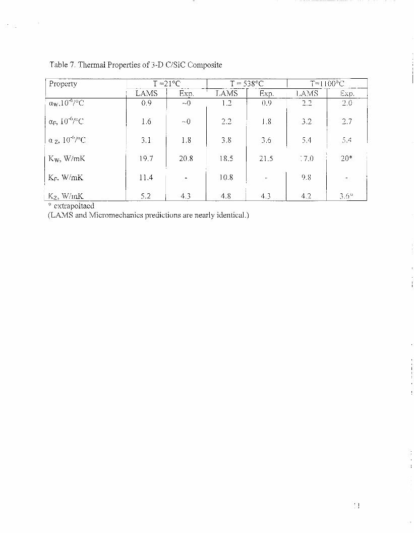
Table 7. Thermal Properties of 3-D C/SiC Coiiiposite
Property
aw, 1 0-"/0c
T =2loC LAMS
0.9
1.6
3.1
19.7
11.4
5.2
Exp . -0
-0
1.8
20.8
4.3
T = 538°C
2.2
3.8
18.5
10.8
4.8 extrapoltaed
[LAMS and Micromechanics predictions are nearly ideiitical.)
Exp. 0.9
I .8
3.6
21.5
4.3
T=llOO°C LAMS 7 7
3.2
5.4
17.0
0.8
4.2
I~sp . 2.0
2.7
5.4
j , 6 :I:
I 1

FIGURES Cross-over points
Z
t ’
.-
Z 1 2
7 1-1 2-2
Single Tow
Two Tows Twisted
c Y
Z t
-+ S
Figure 1. Geometric and modeling details of the 3-D Angle Interlock woven CMC composite system.
f I
Figure 2. Sketch of frame used to siiiiulate 3-D Angle Interlock Composite

Figure 3 . Sketch showing the position of spring elements iii the finite element model.
Z t 1-1 2-2
Single Tow
Two Tows Twisted
Y Y- Figure 4. Details of slicing of the representative volume element of 3-D Angle Interlock weave.

a) Unit Cell
Intei-phase
\
Matrix
b) Slice
Figure 5 . Representative volume element (RVE) for CMC's.
Z t
8 [90] plies 5 [+e] plies
t X
f
5 [-e] plies
Figure 6. Superposition details of [90], and [rt 01 plies to approximate the 3-D Angle Interlock woven composite.