requirements engineered into practice: ceramic matrix
TRANSCRIPT
cfi/Ber. DKG 95 (2018) No. 4-5 E 1
process engineering
Productivity leads to a new heat treatment concept
The market price for a component is the key driver for productive manufacturing. The market is subject to constant change and this produces progress and innova-tion. Cost pressure and the demand for increased effi ciency in case hardening in automobile gearbox production have led to the one-piece fl ow concept. The required heat treatment is integrated into the pro-cess directly after mechanical soft machin-ing and synchronised with the infl ow of soft and the outfl ow of hard components. This gives rise to treatment of individual parts in a continual fl ow of parts, which leads to increased productivity compared to conven-
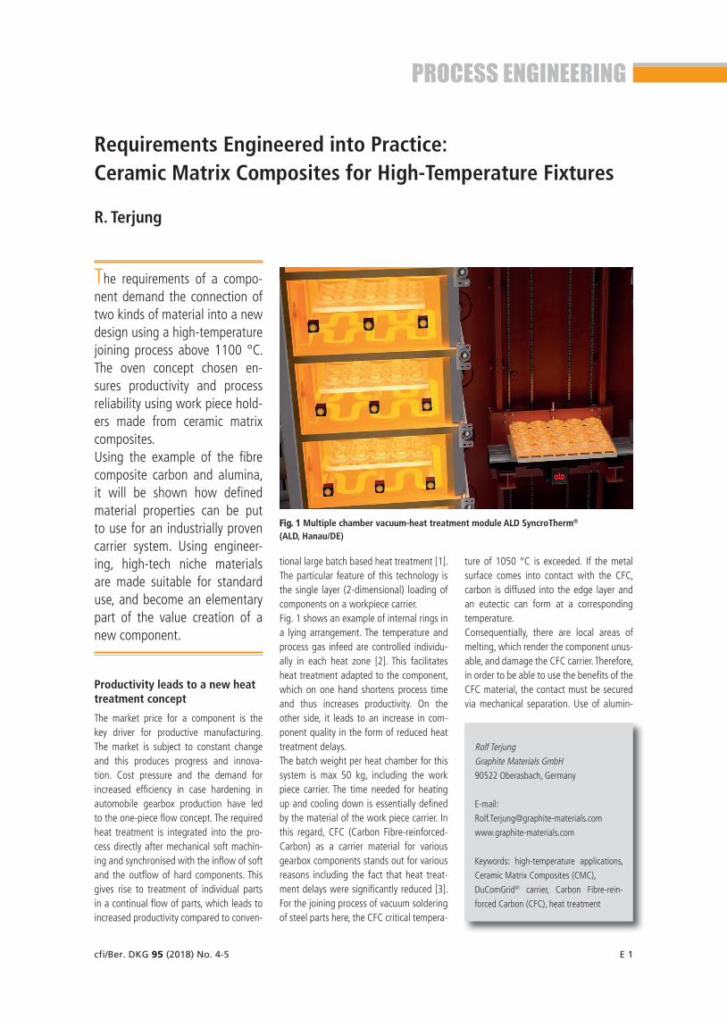
tional large batch based heat treatment [1]. The particular feature of this technology is the single layer (2-dimensional) loading of components on a workpiece carrier. Fig. 1 shows an example of internal rings in a lying arrangement. The temperature and process gas infeed are controlled individu-ally in each heat zone [2]. This facilitates heat treatment adapted to the component, which on one hand shortens process time and thus increases productivity. On the other side, it leads to an increase in com-ponent quality in the form of reduced heat treatment delays.The batch weight per heat chamber for this system is max 50 kg, including the work piece carrier. The time needed for heating up and cooling down is essentially defi ned by the material of the work piece carrier. In this regard, CFC (Carbon Fibre-reinforced-Carbon) as a carrier material for various gearbox components stands out for various reasons including the fact that heat treat-ment delays were signifi cantly reduced [3]. For the joining process of vacuum soldering of steel parts here, the CFC critical tempera-
ture of 1050 °C is exceeded. If the metal surface comes into contact with the CFC, carbon is diffused into the edge layer and an eutectic can form at a corresponding temperature. Consequentially, there are local areas of melting, which render the component unus-able, and damage the CFC carrier. Therefore, in order to be able to use the benefi ts of the CFC material, the contact must be secured via mechanical separation. Use of alumin-
Requirements Engineered into Practice: Ceramic Matrix Composites for High-Temperature Fixtures
R. Terjung
The requirements of a compo-nent demand the connection of two kinds of material into a new design using a high-temperature joining process above 1100 °C. The oven concept chosen en-sures productivity and process reliability using work piece hold-ers made from ceramic matrix composites. Using the example of the fi bre composite carbon and alumina, it will be shown how defi ned material properties can be put to use for an industrially proven carrier system. Using engineer-ing, high-tech niche materials are made suitable for standard use, and become an elementary part of the value creation of a new component.
Fig. 1 Multiple chamber vacuum-heat treatment module ALD SyncroTherm®
(ALD, Hanau/DE)
Rolf Terjung
Graphite Materials GmbH
90522 Oberasbach, Germany
E-mail:
www.graphite-materials.com
Keywords: high-temperature applications,
Ceramic Matrix Composites (CMC),
DuComGrid® carrier, Carbon Fibre-rein-
forced Carbon (CFC), heat treatment
E 2 cfi/Ber. DKG 95 (2018) No. 4-5
process engineering
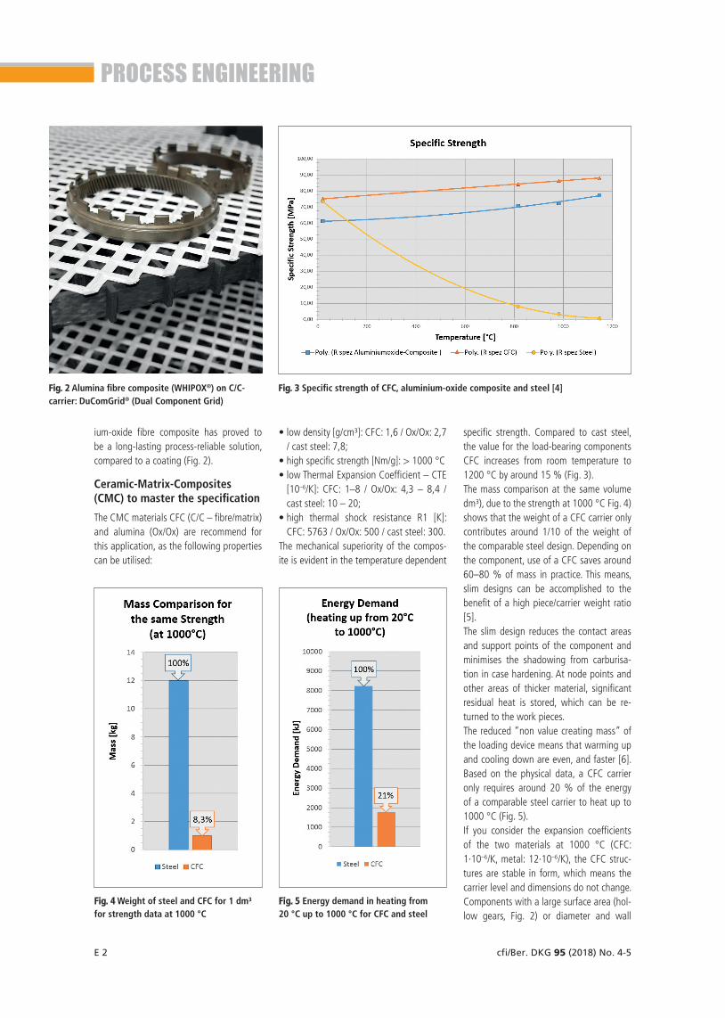
specific strength. Compared to cast steel, the value for the load-bearing components CFC increases from room temperature to 1200 °C by around 15 % (Fig. 3).The mass comparison at the same volume dm³), due to the strength at 1000 °C Fig. 4) shows that the weight of a CFC carrier only contributes around 1/10 of the weight of the comparable steel design. Depending on the component, use of a CFC saves around 60–80 % of mass in practice. This means, slim designs can be accomplished to the benefit of a high piece/carrier weight ratio [5].The slim design reduces the contact areas and support points of the component and minimises the shadowing from carburisa-tion in case hardening. At node points and other areas of thicker material, significant residual heat is stored, which can be re-turned to the work pieces. The reduced “non value creating mass” of the loading device means that warming up and cooling down are even, and faster [6]. Based on the physical data, a CFC carrier only requires around 20 % of the energy of a comparable steel carrier to heat up to 1000 °C (Fig. 5).If you consider the expansion coefficients of the two materials at 1000 °C (CFC: 1·10–6/K, metal: 12·10–6/K), the CFC struc-tures are stable in form, which means the carrier level and dimensions do not change. Components with a large surface area (hol-low gears, Fig. 2) or diameter and wall
• low density [g/cm³]: CFC: 1,6 / Ox/Ox: 2,7 / cast steel: 7,8;
• high specific strength [Nm/g]: > 1000 °C• low Thermal Expansion Coefficient – CTE
[10–6/K]: CFC: 1–8 / Ox/Ox: 4,3 – 8,4 / cast steel: 10 – 20;
• high thermal shock resistance R1 [K]: CFC: 5763 / Ox/Ox: 500 / cast steel: 300.
The mechanical superiority of the compos-ite is evident in the temperature dependent
ium-oxide fibre composite has proved to be a long-lasting process-reliable solution, compared to a coating (Fig. 2).
Ceramic-Matrix-Composites (CMC) to master the specification
The CMC materials CFC (C/C – fibre/matrix) and alumina (Ox/Ox) are recommend for this application, as the following properties can be utilised:
Fig. 2 Alumina fibre composite (WHIPOX®) on C/C-carrier: DuComGrid® (Dual Component Grid)
Fig. 3 Specific strength of CFC, aluminium-oxide composite and steel [4]
Fig. 4 Weight of steel and CFC for 1 dm³ for strength data at 1000 °C
Fig. 5 Energy demand in heating from 20 °C up to 1000 °C for CFC and steel

process engineering
cfi/Ber. DKG 95 (2018) No. 4-5 E 3
processing (sawing, milling, water spraying) of semi-finished parts (sheets, mesh, pipes) define aluminium oxide composite as the base (separation). The simulation of differ-ent designs led to the design as shown in Fig. 6. The variance in component length is assured by supports of different lengths. The oxide ceramic takes over acceptance of the components and is fixed on the CFC strips (Fig. 7).The ceramic elements are integrated into the CFC structure, with precise positioning. If required, elements may be replaced. The differing coefficients of expansion mean that design measures on the fixing are needed, to ensure the loading of the com-ponent base can be repeated accurately in the case of automatic loading.
made in recent years through research and industrial application (Atmospheric Plasma Spray – APS of ceramic powders), however there is still potential in development in-cluding adhesion to sharp edges with re-gard to shock sensitivity [9]. If you validate the cost to benefit relationship for process reliability the APS coats are not competitive in terms of cost compared to the material combination CFC/aluminium oxide compos-ite (Ox/Ox).From a materials technology viewpoint (ma-terials parameters), the solution for a work piece carrier lies in the combination of both composites. Due to the reliability from vari-ous industrial applications, CFC is selected at the carrying element. Experiences from heat treatment, in association with simple
thickness differences (waves) are prone to delay. Deformations of the work piece car-rier, which are transferred directly to the components, can be ignored with CFC.Heat treatment processes such as case hardening or quenching and tempering of-ten include enforced abrupt cooling using gas (High-Pressure Gas Quenching: HPGQ) or liquid media (oil, polymer). The work piece carriers are exposed to an extreme thermal shock which is physically described by the thermal shock coefficient R1 [K] for infinitely large heat transfer in initial prox-imity [7]. Fibre composites are superior to materials with a monolithic structure due to the property combination of fibre and matrix [8]. The properties already listed, strength (flexural strength for CFC and Ox/Ox) and CTE also express the advantages of using CFC as a work piece carrier via the R1-coefficient.As well as the advantages, there are also limits on composites. In atmospheres con-taining air and oxygen, CFC can be used up to a maximum of 350 °C, in order to avoid oxidation damage. In a vacuum, or in an oxygen-free atmosphere above 1050 °C, there may be surface reactions where metal and CFC touches (C-concentration, local melting). With regard to alumina compos-ites, the maximum application temperature (1200 °C) should be observed [9].
Engineered solutions by combination
The case here involves a component which arises through the joining of at least two metal components in a vacuum soldering process. The components may not be shown currently for reasons of data protection. The process is carried out above 1050 °C and requires mechanical separation from the CFC surface. The number of parts per furnace run (load pattern) and loading po-sition (lying and hanging) and component variation (geometry and dimension) make CFC the preferred carrier material. Auto-mated loading is envisaged in the further course of process optimisation. The soft-ware-controlled positioning on the base requires delay-free component nests over the life-cycle of the carrier.The permanent, certain separation of con-tact between metal and CFC on surfaces and edges of the loading device rules out a coating solution. Progress has, indeed, been
Fig. 6 Basic design of CFC carrier for a soldering process
Fig. 7 DuComGrid® carrier, comprising CFC-rack and alumina-fibre composite

process engineering
E 4 cfi/Ber. DKG 95 (2018) No. 4-5
References
[1] Löser, K:. Fertigungsintegrierte Vakuum-Wärme-
behandlungssysteme in der Automobilindustrie.
elektrowärme international. (2016) [1]
[2] ALD Vacuum Technologies GmbH: SyncroTherm
One-Piece-Flow-Prinzip in der Wärmebehand-
lung, Prospekt, appeal 027602
[3] Heuer, V.; Löser, K.; Leist, Th.; Bolton, D.: Enhanc-
ing Control of Distortion Through “One-Piece-
Flow” Heat Treatment. gearsolutions.com, July
2013
[4] Graphite Materials GmbH: www.graphite-mate-
rials.com. Datenblatt Spezifische Festigkeit
[5] Terjung, R.; et al.: Vorteile von CFC-Gestellen
beim Einsatzhärten im Automobilbau. elek-
trowärme international (2017) [1]
[6] Terjung, Rolf. Qualitätsverbesserung durch CFC-
Werkstückträger in der Vakuum-Wärmebehand-
lung. elektrowärme international (2016) [3]
[7] https://de.wikipedia.org/wiki/Thermische_Span-
nung_(Mechanik). [Online]
[8] Raether, F.: Ceramic Matrix Composites - an
Alternative for Challenging Construction Tasks.
CERAMIC APPLICATIONS 1 (2013) [1] 45–49
[9] COI CERAMICS: Inc. Datenblatt trade name
A/N720. 28 June 2017
[10] Drehmann, R.; et al.: Hochtemperaturbestän-
dige, thermisch gespritzte Diffusionsbarriere-
schichten auf CFC Leichtbauchargiergestellen.
elektrowärme international (2013) [1]
ceptance. Semi-finished goods in the form of sheets, pipes and profiles can be pro-cessed into components with state-of-the-art technology. Production at an industrial scale has cre-ated reproducible materials parameters for thermal and mechanical simulation of de-signs. The experiences from a range of dif-ferent applications have fed back into the engineering, supporting solutions in new areas of application.
Conclusion
Using engineering as a combination of ma-terials technology, design and production, different materials can be functionalised into new components. Progress and devel-opment of materials, software (simulation, CAD, CAM) and processing strategies facili-tate new design possibilities for combina-tion of materials (Fig. 8).Both composites have moved out of the high-tech speciality materials niche into what is now a broad area of industrial ac-
Fig. 8 Engineering as a process of Design – Simulation – Production