measurements & instruments post deflection acceleration by : anan ashour
TRANSCRIPT
Measurements & Instruments
Post Deflection Acceleration
By : Anan Ashour
The amount of light given off by the phosphor screen depends on the amount of energy that is transferred to the phosphor by the electron beam.If the electron beam is to be deflected at a rapid rate, allowing the oscilloscope to respond to fast occurring events, the velocity of the electron beam must be great otherwise, the light output will drop off.
For a fast oscilloscope it is desirable to accelerate the electron beam to the greatest amount possible, while on the other hand the greater electron beam velocity will make it more difficult to deflect the beam.
The greater the accelerating potential the more difficult it is to deflect the electron beam.
This would require higher deflection voltages, but, more important, because thevoltage is higher the time change of voltage, that is, dV/dt, is also greater.This would require not only higher voltage for deflection but higher currents to charge the capacitance of the deflection plates.
This becomes a very significant problem for high-frequency oscilloscopes withfrequency responses greater than 100 MHz.Modern cathode ray tubes use a two-step acceleration to eliminate this problem :
First : Scan Expansion Mesh
the electron beam is accelerated to a relatively low velocity through a potential of afew thousand volts. The beam is then deflected and, after deflection, is further accelerated to the desired final velocity. The amount of acceleration after thedeflection does not affect the deflection sensitivity. This type of cathode ray tube iscalled the post deflection acceleration tube
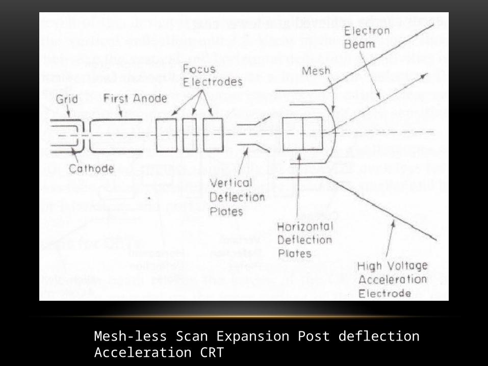
Mesh-less Scan Expansion Post deflection Acceleration CRT
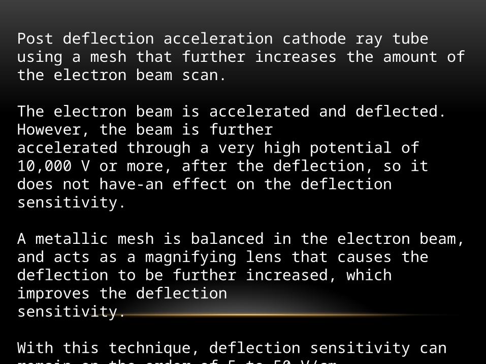
Post deflection acceleration cathode ray tube using a mesh that further increases the amount of the electron beam scan.
The electron beam is accelerated and deflected. However, the beam is further accelerated through a very high potential of 10,000 V or more, after the deflection, so it does not have-an effect on the deflection sensitivity.
A metallic mesh is balanced in the electron beam, and acts as a magnifying lens that causes the deflection to be further increased, which improves the deflectionsensitivity.
With this technique, deflection sensitivity can remain on the order of 5 to 50 V/cmeven though the total electron beam acceleration is more than 10,000 V.
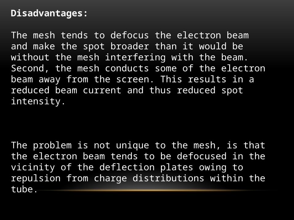
Disadvantages:
The mesh tends to defocus the electron beam and make the spot broader than it would be without the mesh interfering with the beam. Second, the mesh conducts some of the electron beam away from the screen. This results in a reduced beam current and thus reduced spot intensity.
The problem is not unique to the mesh, is that the electron beam tends to be defocused in the vicinity of the deflection plates owing to repulsion from charge distributions within the tube.
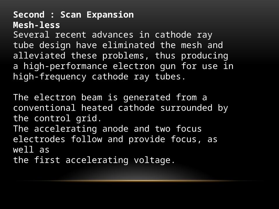
Second : Scan Expansion Mesh-less
Several recent advances in cathode ray tube design have eliminated the mesh and alleviated these problems, thus producing a high-performance electron gun for use inhigh-frequency cathode ray tubes.
The electron beam is generated from a conventional heated cathode surrounded by the control grid.The accelerating anode and two focus electrodes follow and provide focus, as well asthe first accelerating voltage.
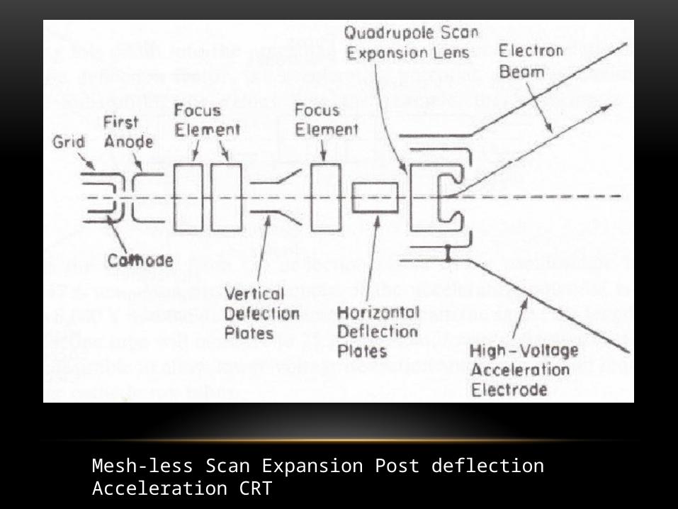
Mesh-less Scan Expansion Post deflection Acceleration CRT

These focus electrodes different from the cylindrical elements used in the conventional tube in that they are constructed from individual metal wafers with non-cylindrical holes in the center.This allows for a different focusing characteristic in the horizontal plane and the vertical plane, typically divergent in one plane being convergent in the other.The holes in the center of the metal wafers can be formed with greater precision thanin a formed cylinder, and thus greater tolerances can be achieved at a lower cost.After the two focusing electrodes, the beam passes through the vertical deflection plates.The beam at this point is not fully focused, which decreases the amount of beam distortion due to the internal charge distributions.
The beam will be further focused after deflection to provide: a fine spot.After vertical deflection, the beam passes through a scan expansion lens that increases the amount of beam bending in the vertical plane.
The beam is then deflected in the horizontal direction and passed through another electron lens, which provides additional focusing.The beam is accelerated to the final velocity by a quadrupole lens, which provides notonly an increase in electron velocity, but adds to the scan angle (scan expansion,which is similar to the mesh ) without distorting or defocusing the electron beam.
The result of this design is increased deflection sensitivity, typically 2.3 V/cm for thevertical deflection and 3.7 V/cm in the horizontal direction.
The difference between the vertical and horizontal deflection sensitivities is due to thefact that the vertical deflection occurs at a lower beam velocity.
Because the horizontal deflection of the oscilloscope involves only a time linear sweep, while the vertical deflection requires complex waveforms, the more sensitive deflection should be reserved for the vertical direction.
Using the mesh-less electron gun, 100-MHz plus oscilloscopes can be constructedwith integrated circuits using only 40 or 50 V or even less for deflection.
The mesh-less tube is being considerably shorter, results in smaller and lighter oscilloscopes for laboratory and portable use

Welcome