mbt mechanically- bolted couplers - home | ancon … bolt reduced diameter shear plane serrated...
TRANSCRIPT
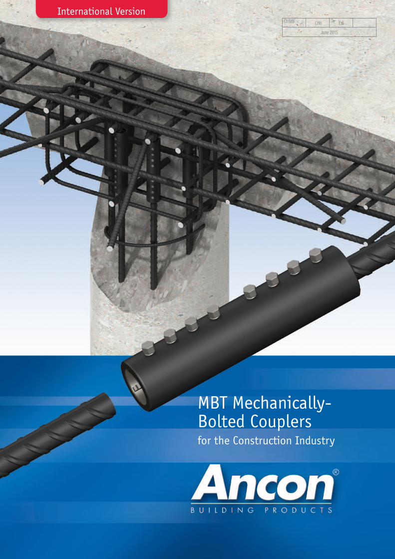
MBT Mechanically-Bolted Couplersfor the Construction Industry
CI/SfB (29) Et6
June 2015
International Version
2 Tel: +44 (0) 114 275 5224 www.ancon.co.uk
Lapped joints are not always anappropriate means of connectingreinforcing bars. The use of lapscan be time consuming in termsof design and installation andcan lead to greater congestionwithin the concrete because ofthe increased amount of rebarused.
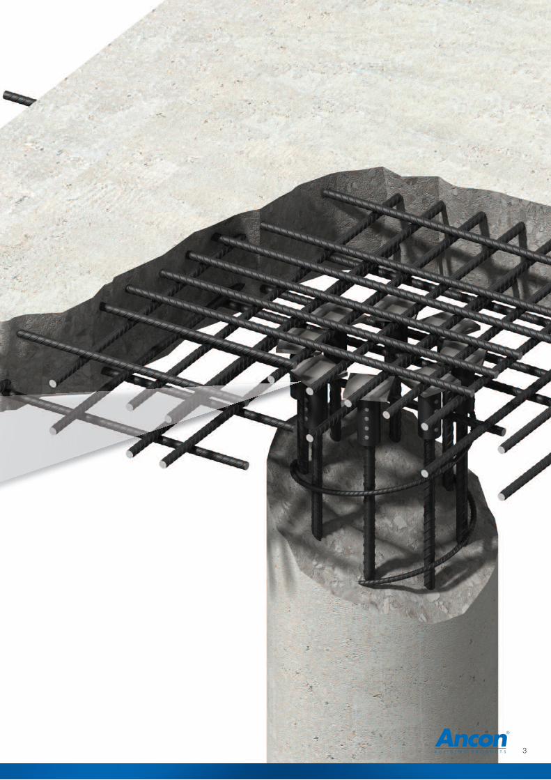
Ancon couplers can simplify thedesign and construction ofreinforced concrete and reducethe amount of reinforcementrequired.
Lapped joints are dependentupon the concrete for loadtransfer. For this reason anydegradation in the integrity of
the concrete could significantlyaffect the performance of thejoint. The strength of amechanical splice is independentof the concrete in which it islocated and will retain itsstrength despite loss of cover asa result of impact damage orseismic event.
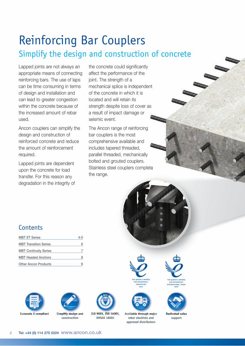
The Ancon range of reinforcingbar couplers is the mostcomprehensive available andincludes tapered threaded,parallel threaded, mechanicallybolted and grouted couplers.Stainless steel couplers completethe range.
Reinforcing Bar CouplersSimplify the design and construction of concrete
MBT ET Series 4-5
MBT Transition Series 6
MBT Continuity Series 7
MBT Headed Anchors 8
Other Ancon Products 9
Contents
ISO 9001, ISO 14001,OHSAS 18001
Available through majorrebar stockists and
approved distributors
Dedicated salessupport
Eurocode 2 compliant Simplify design andconstruction
3
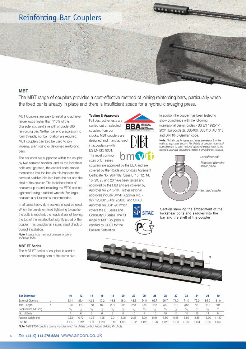
MBT Couplers are easy to install and achievefailure loads higher than 115% of thecharacteristic yield strength of grade 500reinforcing bar. Neither bar end preparation toform threads, nor bar rotation are required.MBT couplers can also be used to joinimperial, plain round or deformed reinforcingbars.
The bar ends are supported within the couplerby two serrated saddles, and as the lockshearbolts are tightened, the conical ends embedthemselves into the bar. As this happens theserrated saddles bite into both the bar and theshell of the coupler. The lockshear bolts ofcouplers up to and including the ET20 can betightened using a ratchet wrench. For largercouplers a nut runner is recommended.
In all cases heavy duty sockets should be used.When the pre-determined tightening torque forthe bolts is reached, the heads shear off leavingthe top of the installed bolt slightly proud of thecoupler. This provides an instant visual check ofcorrect installation.Note: Impact tools must not be used to tightenlockshear bolts.
MBT ET SeriesThe MBT ET series of couplers is used toconnect reinforcing bars of the same size.
Bar Diameter 10 12 14 16 18 20 22 25 26 28 30 32 34 36 40
External Diameter d 33.4 33.4 42.2 42.2 48.3 48.3 48.3 54.0 66.7 66.7 71.0 71.0 75.0 85.0 81.0
Total Length l 100 140 160 160 204 204 248 258 312 312 312 312 420 484 484
Socket Size A/F (ins) 1/21/2
1/21/2
1/21/2
1/25/8
5/85/8
5/85/8
3/43/4
3/4
No. of Bolts 4 6 6 6 8 8 10 8 10 10 10 10 12 14 14
Approx Weight (kg) 0.52 0.72 1.25 1.25 2.0 1.96 2.38 3.00 5.91 5.80 6.68 6.50 8.85 15.30 11.30
Part No. ET10 ET12 ET14 ET16 ET18 ET20 ET22 ET25 ET26 ET28 ET30 ET32 ET34 ET36 ET40
Note: MBT ET50 couplers can be manufactured. For details contact Ancon Building Products.
l
d
4 Tel: +44 (0) 114 275 5224 www.ancon.co.uk
MBTThe MBT range of couplers provides a cost-effective method of joining reinforcing bars, particularly whenthe fixed bar is already in place and there is insufficient space for a hydraulic swaging press.
Section showing the embedment of thelockshear bolts and saddles into thebar and the shell of the coupler
Lockshear bolt
Reduced diametershear plane
Serrated saddle
Reinforcing Bar Couplers
In addition the coupler has been tested toshow compliance with the followinginternational design codes:- BS EN 1992-1-1:2004 (Eurocode 2), BS5400, BS8110, ACI 318and DIN 1045 German code.Note: Not all coupler types and sizes are relevant to thenational approvals shown. For details of coupler types andsizes relevant to each national approval please refer to therelevant approval document, which is available on request.
Testing & ApprovalsFull destructive tests are carried out on selected couplers from our stocks. MBT couplers are designed and manufactured in accordance with BS EN ISO 9001. The most common sizes of ET series couplers are approved by the BBA and arecovered by the Roads and Bridges AgrémentCertificate No. 98/R102. Sizes ET10, 12, 14,16, 20, 25 and 28 have been tested andapproved by the DIBt and are covered byApproval No Z-1.5-10. Further nationalapprovals include BMVIT Approval No. -327.120/0018-II/ST2/2006, and SITACApproval No.0541-95 whichcovers the ET Series andContinuity C Series. The fullrange of MBT Couplers is certified by GOST for the Russian Federation.
CERTIFICATE No 98/R102
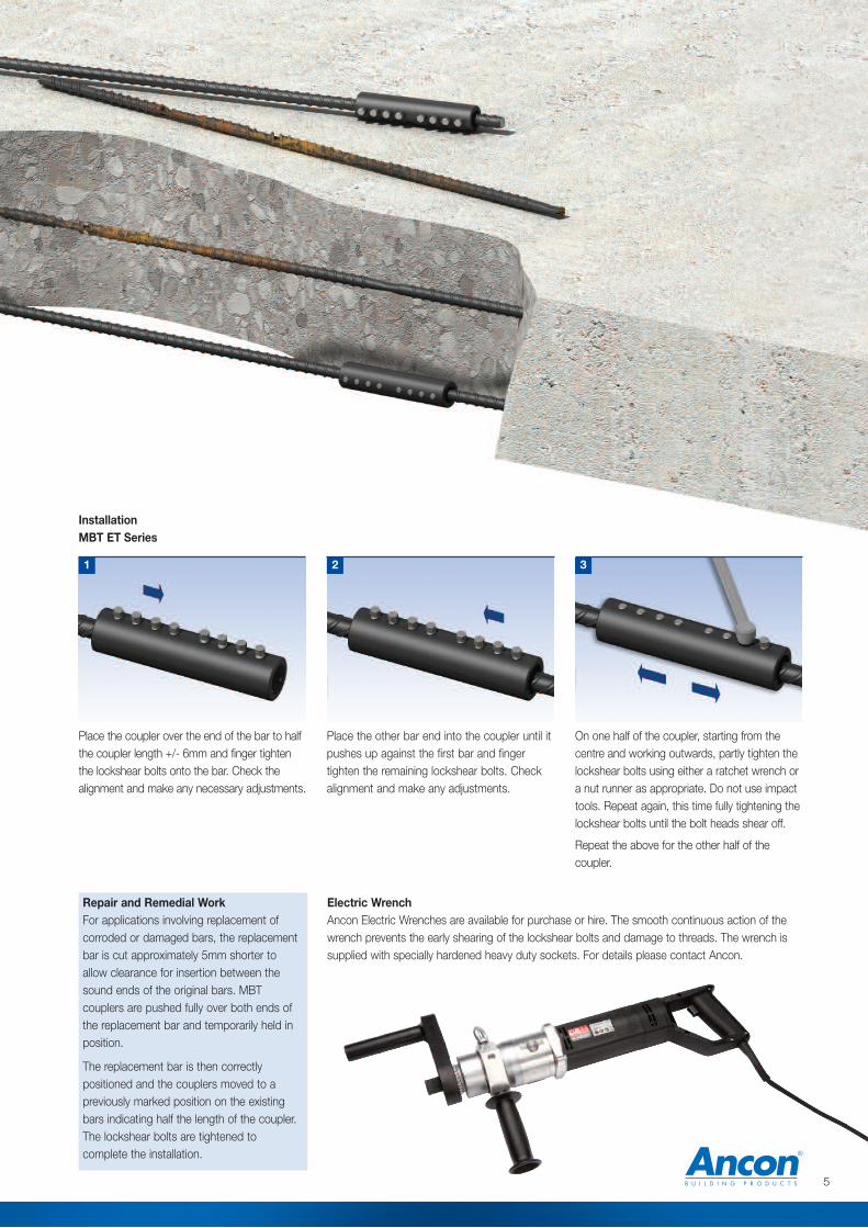
Place the other bar end into the coupler until itpushes up against the first bar and fingertighten the remaining lockshear bolts. Checkalignment and make any adjustments.
On one half of the coupler, starting from thecentre and working outwards, partly tighten thelockshear bolts using either a ratchet wrench ora nut runner as appropriate. Do not use impacttools. Repeat again, this time fully tightening thelockshear bolts until the bolt heads shear off.
Repeat the above for the other half of thecoupler.
2 3
InstallationMBT ET Series
Place the coupler over the end of the bar to halfthe coupler length +/- 6mm and finger tightenthe lockshear bolts onto the bar. Check thealignment and make any necessary adjustments.
1
5
Repair and Remedial WorkFor applications involving replacement ofcorroded or damaged bars, the replacementbar is cut approximately 5mm shorter toallow clearance for insertion between thesound ends of the original bars. MBTcouplers are pushed fully over both ends ofthe replacement bar and temporarily held inposition.
The replacement bar is then correctlypositioned and the couplers moved to apreviously marked position on the existingbars indicating half the length of the coupler.The lockshear bolts are tightened tocomplete the installation.
Electric WrenchAncon Electric Wrenches are available for purchase or hire. The smooth continuous action of thewrench prevents the early shearing of the lockshear bolts and damage to threads. The wrench issupplied with specially hardened heavy duty sockets. For details please contact Ancon.
l
a
d
b
d2
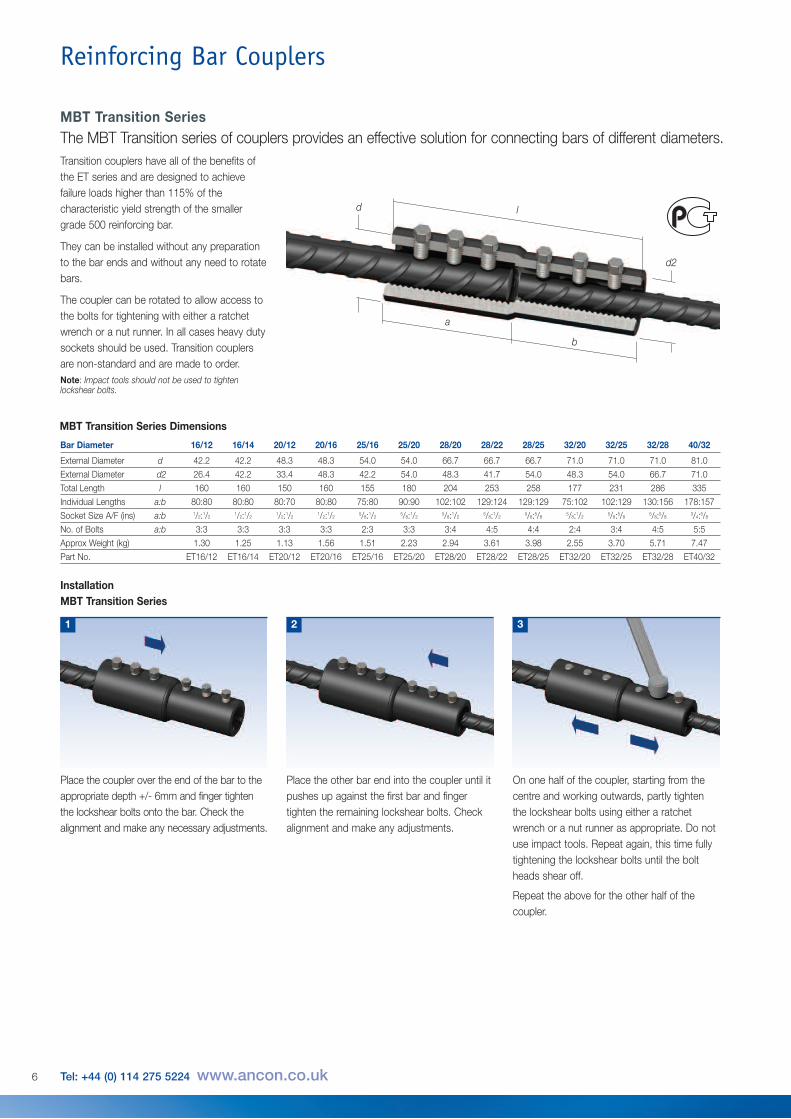
MBT Transition Series Dimensions
Bar Diameter 16/12 16/14 20/12 20/16 25/16 25/20 28/20 28/22 28/25 32/20 32/25 32/28 40/32
External Diameter d 42.2 42.2 48.3 48.3 54.0 54.0 66.7 66.7 66.7 71.0 71.0 71.0 81.0
External Diameter d2 26.4 42.2 33.4 48.3 42.2 54.0 48.3 41.7 54.0 48.3 54.0 66.7 71.0
Total Length l 160 160 150 160 155 180 204 253 258 177 231 286 335
Individual Lengths a:b 80:80 80:80 80:70 80:80 75:80 90:90 102:102 129:124 129:129 75:102 102:129 130:156 178:157
Socket Size A/F (ins) a:b 1/2:1/21/2:1/2
1/2:1/21/2:1/2
5/8:1/25/8:1/2
5/8:1/25/8:1/2
5/8:5/85/8:1/2
5/8:5/85/8:5/8
3/4:5/8
No. of Bolts a:b 3:3 3:3 3:3 3:3 2:3 3:3 3:4 4:5 4:4 2:4 3:4 4:5 5:5
Approx Weight (kg) 1.30 1.25 1.13 1.56 1.51 2.23 2.94 3.61 3.98 2.55 3.70 5.71 7.47
Part No. ET16/12 ET16/14 ET20/12 ET20/16 ET25/16 ET25/20 ET28/20 ET28/22 ET28/25 ET32/20 ET32/25 ET32/28 ET40/32
Place the other bar end into the coupler until itpushes up against the first bar and fingertighten the remaining lockshear bolts. Checkalignment and make any adjustments.
2
InstallationMBT Transition Series
Place the coupler over the end of the bar to theappropriate depth +/- 6mm and finger tightenthe lockshear bolts onto the bar. Check thealignment and make any necessary adjustments.
1
On one half of the coupler, starting from thecentre and working outwards, partly tightenthe lockshear bolts using either a ratchetwrench or a nut runner as appropriate. Do notuse impact tools. Repeat again, this time fullytightening the lockshear bolts until the boltheads shear off.
Repeat the above for the other half of thecoupler.
3
Transition couplers have all of the benefits ofthe ET series and are designed to achievefailure loads higher than 115% of thecharacteristic yield strength of the smallergrade 500 reinforcing bar.
They can be installed without any preparationto the bar ends and without any need to rotatebars.
The coupler can be rotated to allow access tothe bolts for tightening with either a ratchetwrench or a nut runner. In all cases heavy dutysockets should be used. Transition couplersare non-standard and are made to order.Note: Impact tools should not be used to tightenlockshear bolts.
6 Tel: +44 (0) 114 275 5224 www.ancon.co.uk
MBT Transition SeriesThe MBT Transition series of couplers provides an effective solution for connecting bars of different diameters.
Reinforcing Bar Couplers
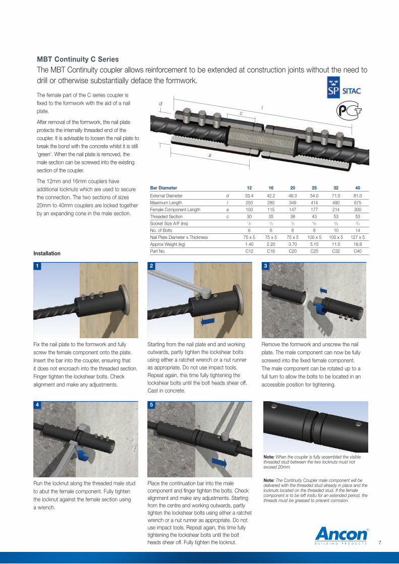
Bar Diameter 12 16 20 25 32 40
External Diameter d 33.4 42.2 48.3 54.0 71.0 81.0
Maximum Length l 250 280 349 414 490 675
Female Component Length a 100 115 147 177 214 300
Threaded Section c 30 35 38 43 53 53
Socket Size A/F (ins) 1/21/2
1/25/8
5/83/4
No. of Bolts 6 6 8 8 10 14
Nail Plate Diameter x Thickness 75 x 5 75 x 5 75 x 5 100 x 5 100 x 5 127 x 5
Approx Weight (kg) 1.40 2.20 3.70 5.15 11.5 18.8
Part No. C12 C16 C20 C25 C32 C40
7
The female part of the C series coupler isfixed to the formwork with the aid of a nailplate.
After removal of the formwork, the nail plateprotects the internally threaded end of thecoupler. It is advisable to loosen the nail plate tobreak the bond with the concrete whilst it is still'green'. When the nail plate is removed, themale section can be screwed into the existingsection of the coupler.
The 12mm and 16mm couplers haveadditional locknuts which are used to securethe connection. The two sections of sizes20mm to 40mm couplers are locked togetherby an expanding cone in the male section.
l
a
d
c
MBT Continuity C SeriesThe MBT Continuity coupler allows reinforcement to be extended at construction joints without the need todrill or otherwise substantially deface the formwork.
Fix the nail plate to the formwork and fullyscrew the female component onto the plate.Insert the bar into the coupler, ensuring that it does not encroach into the threaded section.Finger tighten the lockshear bolts. Checkalignment and make any adjustments.
Run the locknut along the threaded male studto abut the female component. Fully tighten the locknut against the female section using a wrench.
Note: When the coupler is fully assembled the visiblethreaded stud between the two locknuts must notexceed 20mm.
4
Starting from the nail plate end and workingoutwards, partly tighten the lockshear boltsusing either a ratchet wrench or a nut runneras appropriate. Do not use impact tools.Repeat again, this time fully tightening thelockshear bolts until the bolt heads shear off.Cast in concrete.
2
Place the continuation bar into the malecomponent and finger tighten the bolts. Checkalignment and make any adjustments. Startingfrom the centre and working outwards, partlytighten the lockshear bolts using either a ratchetwrench or a nut runner as appropriate. Do notuse impact tools. Repeat again, this time fullytightening the lockshear bolts until the boltheads shear off. Fully tighten the locknut.
5
Installation
1
Remove the formwork and unscrew the nailplate. The male component can now be fullyscrewed into the fixed female component.The male component can be rotated up to afull turn to allow the bolts to be located in anaccessible position for tightening.
3
Note: The Continuity Coupler male component will bedelivered with the threaded stud already in place and thelocknuts located on the threaded stud. If the femalecomponent is to be left insitu for an extended period, thethreads must be greased to prevent corrosion.
Reinforcing Bar Couplers
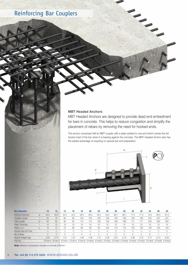
Bar Diameter 10 12 14 16 18 20 22 25 26 28 30 32 34 36 40
External Diameter d 33.4 33.4 42.2 42.2 48.3 48.3 48.3 54.0 66.7 66.7 71.0 71.0 75.0 85.0 81.0
Coupler Length l 55 75 82 82 104 104 126 129 156 156 156 156 215 247 247
Total Length lo 65 85 92 92 114 114 136 139 168 168 171 171 230 262 262
Plate Thickness t 10 10 10 10 10 10 10 10 12 12 15 15 15 15 15
Plate w x h p 70 70 70 80 90 90 90 100 110 110 130 130 130 150 150
Socket Size A/F (ins) 1/21/2
1/21/2
1/21/2
1/25/8
5/85/8
5/85/8
3/43/4
3/4
No of Bolts 2 3 3 3 4 4 5 4 5 5 5 5 6 7 7
Approx Weight (kg) 0.64 0.74 1.01 1.07 1.58 1.58 1.72 2.29 3.81 4.14 5.08 4.72 5.17 9.13 8.30
Part No. ETHA10 ETHA12 ETHA14 ETHA16 ETHA18 ETHA20 ETHA22 ETHA25 ETHA26 ETHA28 ETHA30 ETHA32 ETHA34 ETHA36 ETHA40
Note: Minimum compressive strength of concrete 25N/mm2.
l
t
p
d
lo
MBT Headed AnchorsMBT Headed Anchors are designed to provide dead end embedmentfor bars in concrete. This helps to reduce congestion and simplify theplacement of rebars by removing the need for hooked ends.
The anchor comprises half an MBT coupler with a plate welded to one end which carries the fulltension load of the bar when it is bearing against the concrete. The MBT Headed Anchor also hasthe added advantage of requiring no special bar end preparation.
8 Tel: +44 (0) 114 275 5224 www.ancon.co.uk
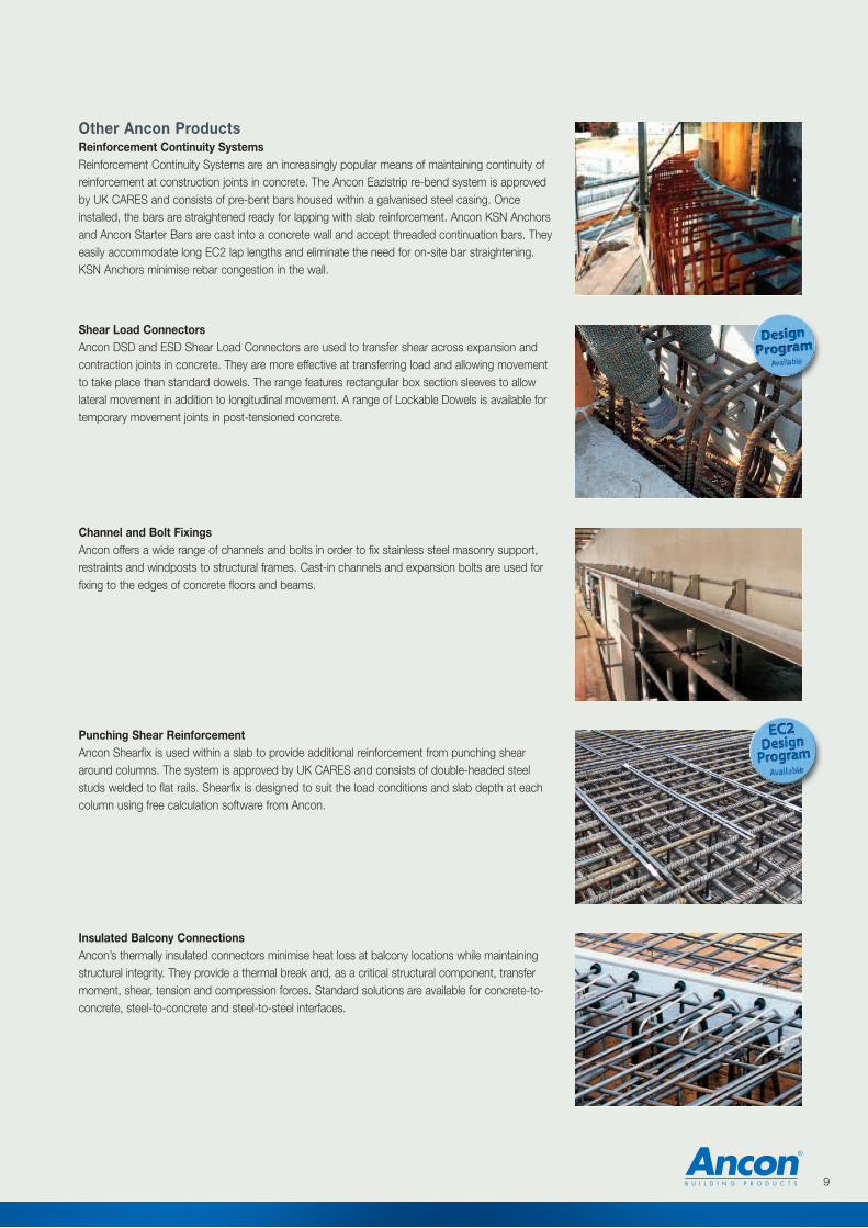
Other Ancon ProductsReinforcement Continuity SystemsReinforcement Continuity Systems are an increasingly popular means of maintaining continuity ofreinforcement at construction joints in concrete. The Ancon Eazistrip re-bend system is approvedby UK CARES and consists of pre-bent bars housed within a galvanised steel casing. Onceinstalled, the bars are straightened ready for lapping with slab reinforcement. Ancon KSN Anchorsand Ancon Starter Bars are cast into a concrete wall and accept threaded continuation bars. Theyeasily accommodate long EC2 lap lengths and eliminate the need for on-site bar straightening.KSN Anchors minimise rebar congestion in the wall.
Shear Load ConnectorsAncon DSD and ESD Shear Load Connectors are used to transfer shear across expansion andcontraction joints in concrete. They are more effective at transferring load and allowing movementto take place than standard dowels. The range features rectangular box section sleeves to allowlateral movement in addition to longitudinal movement. A range of Lockable Dowels is available fortemporary movement joints in post-tensioned concrete.
Channel and Bolt FixingsAncon offers a wide range of channels and bolts in order to fix stainless steel masonry support,restraints and windposts to structural frames. Cast-in channels and expansion bolts are used forfixing to the edges of concrete floors and beams.
Punching Shear ReinforcementAncon Shearfix is used within a slab to provide additional reinforcement from punching sheararound columns. The system is approved by UK CARES and consists of double-headed steelstuds welded to flat rails. Shearfix is designed to suit the load conditions and slab depth at eachcolumn using free calculation software from Ancon.
Insulated Balcony ConnectionsAncon’s thermally insulated connectors minimise heat loss at balcony locations while maintainingstructural integrity. They provide a thermal break and, as a critical structural component, transfermoment, shear, tension and compression forces. Standard solutions are available for concrete-to-concrete, steel-to-concrete and steel-to-steel interfaces.
9
© Ancon Building Products 2014
These products are available from:
Masonry Support Systems
Lintels
Masonry Reinforcement
Windposts and Parapet Posts
Wall Ties and Restraint Fixings
Channel and Bolt Fixings
Tension and Compression Systems
Insulated Balcony Connectors
Shear Load Connectors
Punching Shear Reinforcement
Reinforcing Bar Couplers
Reinforcement Continuity Systems
Stainless Steel Fabrications
Flooring and Formed Sections
Refractory Fixings
Ancon Building Products98 Kurrajong AvenueMount DruittSydney NSW 2770AustraliaTel: +61 (0) 2 8808 3100Fax: +61 (0) 2 9675 3390Email: [email protected]: www.ancon.com.au
Ancon Building Products2/19 Nuttall DriveHillsboroughChristchurch 8022New ZealandTel: +64 (0) 3 376 5205Fax: +64 (0) 3 376 5206Email: [email protected]: www.ancon.co.nz
Ancon (Schweiz) AGGewerbezone Widalmi 103216 Ried bei KerzersSwitzerlandTel: +41 (0) 31 750 3030Fax: +41 (0) 31 750 3033 Email: [email protected]: www.ancon.ch
Ancon Building ProductsGesmbHPuchgasse 1A-1220 ViennaAustriaTel: +43 (0) 1 259 58 62-0Fax: +43 (0) 1 259 58 62-40Email: [email protected]: www.ancon.at
Ancon GmbHBartholomäusstrasse 2690489 NurembergGermanyTel: +49 (0) 911 955 1234 0Fax: +49 (0) 911 955 1234 9Email: [email protected]: www.anconbp.de
Ancon Building ProductsPresident Way, President ParkSheffield S4 7URUnited KingdomTel: +44 (0) 114 275 5224Fax: +44 (0) 114 276 8543Email: [email protected]: www.ancon.co.ukFollow on Twitter: @AnconUK
Ancon (Middle East) FZEPO Box 17225Jebel AliDubaiUnited Arab EmiratesTel: +971 (0) 4 883 4346Fax: +971 (0) 4 883 4347Email: [email protected]: www.ancon.ae
The construction applications and details provided in this literature are indicative only. In every case, project workingdetails should be entrusted to appropriately qualified and experienced persons.
Whilst every care has been exercised in the preparation of this document to ensure that any advice, recommendations orinformation is accurate, no liability or responsibility of any kind is accepted in respect of Ancon Building Products.
With a policy of continuous product development Ancon Building Products reserves the right to modify product designand specification without due notice.